Using the Avid Mojo SDI - Digidesignakmedia.digidesign.com/support/docs/UsingMojo_SDI_35797.pdf ·...
48
a n See the ReadMe file that installs with the application. It contains important information that you should use in conjunction with the information presented in these topics. Important Information Avid ® recommends that you read all the information in these installation instructions thoroughly before connecting or using your new hardware. This document explains how to use and connect cables and devices to the Avid Mojo ™ SDI Digital Nonlinear Accelerator (DNA) and how to connect specific devices to an Avid-supported PC or Macintosh ® system that the Avid Mojo SDI is connected to. The supported PC and Macintosh systems used with your Avid Mojo SDI can change at any time. a Using the Avid Mojo SDI
Transcript of Using the Avid Mojo SDI - Digidesignakmedia.digidesign.com/support/docs/UsingMojo_SDI_35797.pdf ·...

a
n See the ReadMe file that installs with the application. It contains important information that you should use in conjunction with the information presented in these topics.
Important Information
Avid® recommends that you read all the information in these installation instructions thoroughly before connecting or using your new hardware.
This document explains how to use and connect cables and devices to the Avid Mojo™ SDI Digital Nonlinear Accelerator (DNA) and how to connect specific devices to an Avid-supported PC or Macintosh® system that the Avid Mojo SDI is connected to. The supported PC and Macintosh systems used with your Avid Mojo SDI can change at any time.
aUsing the Avid Mojo SDI

Using the Avid Mojo SDI
2
Contents
If You Need Help . . . . . . . . . . . . . . . . . . . . . . . . . . . . . . . . . . . . . . . . . . . . . . . . . . . . . . . . . 4
Symbols and Conventions . . . . . . . . . . . . . . . . . . . . . . . . . . . . . . . . . . . . . . . . . . . . . . . . . . 4
Overview. . . . . . . . . . . . . . . . . . . . . . . . . . . . . . . . . . . . . . . . . . . . . . . . . . . . . . . . . . . . . . . . 5
Avid Mojo SDI Front and Rear Panels . . . . . . . . . . . . . . . . . . . . . . . . . . . . . . . . . . . . . . . . . 7
Avid Mojo SDI Front Panel . . . . . . . . . . . . . . . . . . . . . . . . . . . . . . . . . . . . . . . . . . . . . . 8
Avid Mojo SDI Rear Panel . . . . . . . . . . . . . . . . . . . . . . . . . . . . . . . . . . . . . . . . . . . . . . . 9
Avid Video Cable Functions. . . . . . . . . . . . . . . . . . . . . . . . . . . . . . . . . . . . . . . . . . . . . 11
Synchronizing Audio and Video Equipment . . . . . . . . . . . . . . . . . . . . . . . . . . . . . . . . . . . . 12
Power-On Self Tests . . . . . . . . . . . . . . . . . . . . . . . . . . . . . . . . . . . . . . . . . . . . . . . . . . . . . 13
1394 Requirements . . . . . . . . . . . . . . . . . . . . . . . . . . . . . . . . . . . . . . . . . . . . . . . . . . . . . . 13
Connecting Peripheral Equipment . . . . . . . . . . . . . . . . . . . . . . . . . . . . . . . . . . . . . . . . . . . 14
Connecting Analog Audio Signals . . . . . . . . . . . . . . . . . . . . . . . . . . . . . . . . . . . . . . . . 14
Reference for Analog Audio Input. . . . . . . . . . . . . . . . . . . . . . . . . . . . . . . . . . . . . 15
Connecting Digital Audio Signals. . . . . . . . . . . . . . . . . . . . . . . . . . . . . . . . . . . . . . . . . 16
Reference Signal for Digital Audio Output . . . . . . . . . . . . . . . . . . . . . . . . . . . . . . 16
Connecting Digital Audio Cables . . . . . . . . . . . . . . . . . . . . . . . . . . . . . . . . . . . . . 17
Connecting S-Video or DV Signals . . . . . . . . . . . . . . . . . . . . . . . . . . . . . . . . . . . . . . . 18
Connecting SDI Signals. . . . . . . . . . . . . . . . . . . . . . . . . . . . . . . . . . . . . . . . . . . . . . . . 19
Connecting a Client Monitor or Video Deck Using Composite Signals . . . . . . . . . . . . 19
Connecting a Video Deck Using Component Signals . . . . . . . . . . . . . . . . . . . . . . . . . 21
System Connections and Configurations . . . . . . . . . . . . . . . . . . . . . . . . . . . . . . . . . . . . . . 22
Connecting the Application Key. . . . . . . . . . . . . . . . . . . . . . . . . . . . . . . . . . . . . . . . . . 22
HP xw8200 System Slot Configuration and Connections . . . . . . . . . . . . . . . . . . . . . . 23
HP xw8000 System Slot Configuration and Connections . . . . . . . . . . . . . . . . . . . . . . 24
Macintosh Dual Quad Core G5 System. . . . . . . . . . . . . . . . . . . . . . . . . . . . . . . . . . . . 26
Macintosh G5 System Slot Configuration and Connections . . . . . . . . . . . . . . . . . . . . 27
Macintosh G4 System Slot Configuration and Connections . . . . . . . . . . . . . . . . . . . . 28
Connecting Serial and MIDI Port Devices . . . . . . . . . . . . . . . . . . . . . . . . . . . . . . . . . . . . . 29
USB and Serial Differences Between Windows and Macintosh Systems . . . . . . . . . . 29
USB and Serial Connections (Windows Only). . . . . . . . . . . . . . . . . . . . . . . . . . . . . . . 29

3
Connecting the USB Hub . . . . . . . . . . . . . . . . . . . . . . . . . . . . . . . . . . . . . . . . . . . . . . . 30
Connecting the USB Devices to the USB Hub . . . . . . . . . . . . . . . . . . . . . . . . . . . . . . . 31
Connecting the USB-to-Serial Adapter . . . . . . . . . . . . . . . . . . . . . . . . . . . . . . . . . 31
Connecting the USB-to-MIDI Converter . . . . . . . . . . . . . . . . . . . . . . . . . . . . . . . . 32
Connecting JL Cooper Fader Controllers . . . . . . . . . . . . . . . . . . . . . . . . . . . . . . . . . . . 33
Connecting the Yamaha 01V Mixer . . . . . . . . . . . . . . . . . . . . . . . . . . . . . . . . . . . . . . . 35
Connecting the Yamaha 01V/96 Mixer. . . . . . . . . . . . . . . . . . . . . . . . . . . . . . . . . . . . . 36
Controlling a Video Deck . . . . . . . . . . . . . . . . . . . . . . . . . . . . . . . . . . . . . . . . . . . . . . . 36
Storage . . . . . . . . . . . . . . . . . . . . . . . . . . . . . . . . . . . . . . . . . . . . . . . . . . . . . . . . . . . . . . . . 37
SCSI Support . . . . . . . . . . . . . . . . . . . . . . . . . . . . . . . . . . . . . . . . . . . . . . . . . . . . . . . . 37
1394 Support . . . . . . . . . . . . . . . . . . . . . . . . . . . . . . . . . . . . . . . . . . . . . . . . . . . . . . . . 38
Internal IDE Drives . . . . . . . . . . . . . . . . . . . . . . . . . . . . . . . . . . . . . . . . . . . . . . . . . . . . 38
Ethernet Support . . . . . . . . . . . . . . . . . . . . . . . . . . . . . . . . . . . . . . . . . . . . . . . . . . . . . 38
Fibre Channel Support . . . . . . . . . . . . . . . . . . . . . . . . . . . . . . . . . . . . . . . . . . . . . . . . . 38
Formatting and Striping Media Drives (Windows) . . . . . . . . . . . . . . . . . . . . . . . . . . . . 39
Formatting and Striping MediaDrives (Macintosh) . . . . . . . . . . . . . . . . . . . . . . . . . . . . 39
Using Striped Drives on Mac OS X and Mac OS 9.x Systems . . . . . . . . . . . . . . . 40
Moving Striped Drives to Another System (Macintosh Only). . . . . . . . . . . . . . . . . 40
Specifications . . . . . . . . . . . . . . . . . . . . . . . . . . . . . . . . . . . . . . . . . . . . . . . . . . . . . . . . . . . 41
Dimensions and Weight . . . . . . . . . . . . . . . . . . . . . . . . . . . . . . . . . . . . . . . . . . . . . . . . 41
Environmental Specifications . . . . . . . . . . . . . . . . . . . . . . . . . . . . . . . . . . . . . . . . . . . . 42
Electrical Specifications . . . . . . . . . . . . . . . . . . . . . . . . . . . . . . . . . . . . . . . . . . . . . . . . 42
Regulatory and Safety Notices . . . . . . . . . . . . . . . . . . . . . . . . . . . . . . . . . . . . . . . . . . . . . . 43
Warnings and Cautions . . . . . . . . . . . . . . . . . . . . . . . . . . . . . . . . . . . . . . . . . . . . . . . . 43
FCC Notice . . . . . . . . . . . . . . . . . . . . . . . . . . . . . . . . . . . . . . . . . . . . . . . . . . . . . . . . . . . . . 43
Canadian ICES-003 . . . . . . . . . . . . . . . . . . . . . . . . . . . . . . . . . . . . . . . . . . . . . . . . . . . 44
European Union Notice . . . . . . . . . . . . . . . . . . . . . . . . . . . . . . . . . . . . . . . . . . . . . . . . 44
Australia and New Zealand EMC Regulations . . . . . . . . . . . . . . . . . . . . . . . . . . . . . . . 46
Technical Support Information . . . . . . . . . . . . . . . . . . . . . . . . . . . . . . . . . . . . . . . . . . . . . . 47

Using the Avid Mojo SDI
4
If You Need Help
If you are having trouble using Avid Mojo SDI:
1. Retry the action, carefully following the instructions given for that task. It is especially important to check each step of your workflow.
2. Check this ReadMe file for the latest information that might have become available after the documentation was published.
3. Check the documentation that came with your Avid application or your hardware for maintenance or hardware-related issues.
4. Visit Avid Online Support at www.avid.com/onlinesupport/. Online support is available 24 hours per day, 7 days per week. Search the Knowledge Base to find answers, to view error messages, to access troubleshooting tips, to download updates, and to read/join online message-board discussions.
5. For Technical Support, please call 800-800-AVID (800-800-2843).
For Broadcast On-Air Sites and Call Letter Stations, call800-NEWSDNG (800-639-7364).
Symbols and Conventions
These installation instructions use the following symbols and conventions:
Symbol or Convention Meaning or Action
n A note provides important related information, reminders, recommendations, and strong suggestions.
c A caution means that a specific action you take could cause harm to your computer or cause you to lose data.
w A warning describes an action that could cause you physical harm. Follow the guidelines in this document or on the unit itself when handling electrical equipment.
> This symbol indicates menu commands (and subcommands) in the order you select them. For example, File > Import means to open the File menu and then select the Import command.
t This symbol indicates a single-step procedure. Multiple arrows in a list indicate that you perform one of the actions listed.

Overview
5
Overview
The Avid Mojo SDI is designed to capture and output analog media and digital media using digital decks and cameras. It is powered by an autosensing power adapter that plugs into a wall plug or power strip.
The Avid Mojo SDI accepts video and audio in different formats and resolutions, up to and including Avid broadcast standard 1:1 10-bit uncompressed.
You edit the data on the Avid editing system and return it to the Avid Mojo SDI to be changed back to the proper format and resolution as needed for video and audio output.
The Avid Mojo SDI consists of:
• The Avid Mojo SDI
• A stand
• A power adapter with power cord
• Cable kit
The following table list the cables provided with the system:
Cable Kit
Cable Type Quantity
Standard 1394 cable, 6-pin to 6-pin 1
Video Input and Output Breakout Connector
n This cable has a DVI-shaped connection on one end; however it is not a DVI enabled connector. There are seven BNC connections at the other. These cables are specifically design for Avid functionality only. See “Avid Mojo SDI Rear Connectors” on page 9 for explanations of each connection.
2
1/8” Mini-jack to dual RCA connectors 4
S-video to BNC adapter 2

Using the Avid Mojo SDI
6
The following figure shows the cables.
n The standard 6-pin to 6-pin 1394 cable is included in the cable kit, but it is not shown because it is not designed by Avid.
S-video to BNC adapter 1/8” mini-jack to RCA connector
Video input/output cable
Avid Cables

Avid Mojo SDI Front and Rear Panels
7
Avid Mojo SDI Front and Rear Panels
You can place the Avid Mojo SDI in a stand or position it on its side. The Avid Mojo SDI turns on when you connect the power adapter. You attach cables to connect the power, the system, and external devices at the rear.
Avid Mojo SDI in the Stand
VID
EOAU
DIO
AUD
IO
15VD
CO
UTP
UT
3/4
3/4
1/2
1/2
1/2
1/2
INPU
T
VID
EO
HO
STRear
Stand
Front panel

Using the Avid Mojo SDI
8
Avid Mojo SDI Front Panel
The Avid Mojo SDI front panel contains function LEDs behind a cover, a headphone jack, and volume control for the headphones (see the following figure).
n The function LEDs are not labeled on the front panel. You can see the function names through the cover when it is lit.
Avid Mojo SDI Front Panel
The following table describes the LEDs.
CLIP 48KHZ DV REF HOST POWER
Headphone jack Volume controlLEDs
LED Functions
LED Function
Clip Flashes red as audio data is distorted (due to overloading or peaking), and for power-on self-test (POST). See “Power-On Self Tests” on page 13.
48KHz Lit when 48-KHz audio is selected in the application; not lit when 44 KHz or 32 KHz is selected.
DV Lit when the application data is in 1394 mode.
Ref Lit when the Avid Mojo SDI is synced to a reference video source. See “Synchronizing Audio and Video Equipment” on page 12.
Host Lit when the Avid Mojo SDI is connected to the Avid editing system.
Power Lit when the power adapter is connected to the Avid Mojo SDI.

Avid Mojo SDI Front and Rear Panels
9
Avid Mojo SDI Rear Panel
The following figure shows the connections on the rear of the Avid Mojo SDI. The rear connectors are labeled on the device.
Avid Mojo SDI Rear Panel
The connectors are described in the following table.
VIDEOAUDIOAUDIO
15VDCOUTPUT3/43/4 1/21/21/21/2
INPUT
VIDEO
HOST
DV
Host
DV
Video output Video input
Optical S/PDIFinput output
Chans 1 + 2 3 +4 Audio output
DC In
Chans 1 + 2 3 +4 Audio input
Avid Mojo SDI Rear Connectors
Label Function
Host A 6-pin 1394 connector used to input and output audio and video signals to and from the Avid editing system. The Avid Mojo SDI cannot be powered by the 1394 connection.
DV 4-pin 1394 connection, directly connected to the host 1394, that is used to input and output DV 25, DV 50, DVCPro HD, and HDV to and from 1394 decks and cameras.
Video Input This cable has a DVI-shaped connection on one end and seven BNC connections at the other. These cables are specifically design for Avid and cannot function as a standard DVI cable. The 7 cables are color coded and are labeled:
• Purple - AES channels 3 and 4
• Yellow - AES channels1 and 2
• Gray - SDI
• Black - Ref
• Blue - B-Y, composite
• Green - Y, S-Video-Luma
• Red - R-Y, S-Video-Chroma

Using the Avid Mojo SDI
10
Audio Input Two 1/8” connectors used for the four channels 1, 2, 3 and 4. As shown in the figure, they can connect to an analog audio output of a video camera or deck. White is typically used for channels 1 and 3, while red is used for channels 2 and 4.
S/PDIF Input Two channels of optical S/PDIF (no cable provided).
S/PDIF Output Two channels of optical S/PDIF (no cable provided).
Audio Output Two 1/8” connectors used for the four channels 1, 2, 3 and 4. As shown in the figure, they can connect to speakers (most common) or to an analog audio input of a video camera or deck.White is used for channels 1 and 3, while red is used for channels 2 and 4.
Video Output This cable has a DVI-shaped connection on one end and seven BNC connections at the other. These cables are specifically design for Avid and cannot function as a standard DVI cable. See “Video Input and Output Cable Functions” on page 11 for functions. The 7 cables are color coded and are labeled:
• Purple - AES channels 3 and 4
• Yellow - AES channels1 and 2
• Gray - SDI
• Black - Word Clock or S/PDIF when connected to a Digi 002
• Blue - B-Y, composite
• Green - Y, S-Video-Luma
• Red - R-Y, S-Video-Chroma
DC Power Connects to the power adapter.
Avid Mojo SDI Rear Connectors (Continued)
Label Function
Avid Mojo SDI Front and Rear Panels
11
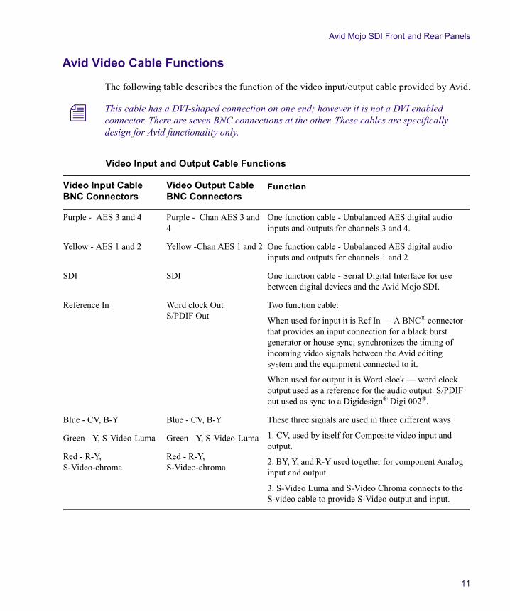
Avid Video Cable Functions
The following table describes the function of the video input/output cable provided by Avid.
n This cable has a DVI-shaped connection on one end; however it is not a DVI enabled connector. There are seven BNC connections at the other. These cables are specifically design for Avid functionality only.
Video Input and Output Cable Functions
Video Input Cable BNC Connectors
Video Output Cable BNC Connectors
Function
Purple - AES 3 and 4 Purple - Chan AES 3 and 4
One function cable - Unbalanced AES digital audio inputs and outputs for channels 3 and 4.
Yellow - AES 1 and 2 Yellow -Chan AES 1 and 2 One function cable - Unbalanced AES digital audio inputs and outputs for channels 1 and 2
SDI SDI One function cable - Serial Digital Interface for use between digital devices and the Avid Mojo SDI.
Reference In Word clock OutS/PDIF Out
Two function cable:
When used for input it is Ref In — A BNC® connector that provides an input connection for a black burst generator or house sync; synchronizes the timing of incoming video signals between the Avid editing system and the equipment connected to it.
When used for output it is Word clock — word clock output used as a reference for the audio output. S/PDIF out used as sync to a Digidesign® Digi 002®.
Blue - CV, B-Y Blue - CV, B-Y These three signals are used in three different ways:
1. CV, used by itself for Composite video input and output.
2. BY, Y, and R-Y used together for component Analog input and output
3. S-Video Luma and S-Video Chroma connects to theS-video cable to provide S-Video output and input.
Green - Y, S-Video-Luma Green - Y, S-Video-Luma
Red - R-Y, S-Video-chroma
Red - R-Y, S-Video-chroma

Using the Avid Mojo SDI
12
Synchronizing Audio and Video Equipment
Avid editing systems require synchronization (sync) when capturing audio and video. A sync signal for analog audio and analog video can also be generated from the connected REF signal coming in on the video input cable, or internally by the Avid Mojo SDI.
n The digital signal from a 1394 device has its own sync signal to which the Avid Mojo SDI synchronizes.
n The S/PDIF output coming from the video output cable provides a digital sync signal when connected to the Digidesign Digi 002 in an Avid Xpress Studio® system.
The following list summarizes how sync works:
• Video Reference IN (REF) from the video input cable — Sync signals are generated from the incoming black burst generator (BBGen) or from a house sync. If there is no sync connected to REF, an internal sync is used.
n By default, the sync signal is generated from incoming video whenever you capture analog video. Depending on the configuration of the audio and video equipment attached to the Avid Mojo SDI, you might need to use a BBGen or house sync, for example, when you perform an Insert Edit.
• Incoming video signal — When you capture video, a sync signal is generated by the Avid Mojo SDI from the incoming video: component, composite, S-video, DV, or SDI.
When you capture analog video and audio, the Avid Mojo SDI generates a sync signal from the incoming video.
• Incoming analog audio — When you capture audio only, the Avid Mojo SDI syncs to the digital analog signal. The Avid Mojo SDI syncs to internal Reference signal if analog audio is selected in an audio-only capture.

Power-On Self Tests
13
Power-On Self Tests
The Avid Mojo SDI runs power-on self tests (POSTs) to determine if the box and the board within the box are operating properly each time you turn the Avid Mojo SDI on.
The LEDs start to flash after the FPGA is downloaded and flash during initialization. If the POST passes and the Host is connected and powered up the HOST and 48KHZ LEDs are on.
If a failure occurs when running a POST, the Clip LED (see “Avid Mojo SDI Front Panel” on page 8) blinks steadily once a second. Also, if the Power LED does not light after you connect the Avid Mojo SDI to the power adapter, the Avid Mojo SDI is not capable of running diagnostics and is not functioning properly. If possible, try another power adapter. If the Avid Mojo SDI does not work with a different power adapter, replace the Avid Mojo SDI.
1394 Requirements
The rear of the Avid Mojo SDI has a 4-pin DV connector used for connecting cameras, decks, or other video devices for input or output. This 1394 connector is wired directly to the host. The 4-pin DV connector does not support 1394 (FireWire®) drives. For connector locations see “Avid Mojo SDI Rear Panel” on page 9.
n Macintosh systems more commonly use the term FireWire, and Windows® systems use the IEEE term of 1394.
n The multiple FireWire connectors on Macintosh systems are on the same bus. You must install a separate 1394 board in Macintosh and Windows systems if you want to attach 1394 drives.
The IEEE 1394 cabling standard requires that IEEE 1394 (FireWire) devices be within 14.76 ft (4.5 m) of the next bus connector. When you connect a FireWire device (drive, camera, or deck), your FireWire cable must not exceed this length. Avid products do not support the use of IEEE 1394 (FireWire) repeaters to boost or extend the signal to the device.
In addition, Avid does not support any type of cable extender or FireWire hub between the Avid editing system connection and the Avid Mojo SDI. If the Avid editing system does not sense a direct connection to the Avid Mojo SDI, the Avid Mojo SDI enters a non-operating mode.

Using the Avid Mojo SDI
14
Connecting Peripheral Equipment
There are several possible cabling configurations depending on your camera, video deck, and client monitor. The audio and video output signals are available to each output connector at the same time. The following sections describe several possible connections:
• Connecting Analog Audio Signals
• Connecting Digital Audio Signals
• Connecting S-Video or DV Signals
• Connecting SDI Signals
• Connecting a Client Monitor or Video Deck Using Composite Signals
• Connecting a Video Deck Using Component Signals
Connecting Analog Audio Signals
There are 4 channels of analog input audio (2 cables) and 4 channels of analog output audio (2 cables) on the rear of the Avid Mojo SDI.
• Four connectors, two input and two output, accept an 1/8-inch mini-jack. You plug the 1/8-inch mini-jack to two RCA connector cables into the connectors.
• The cables connect to a video deck or audio device with audio input and output connections.
To connect analog audio from a deck or audio device:
t Attach the four cables (1/8-inch mini-jacks to RCA connectors) to the audio input connectors and output connectors as shown in “Connecting Analog Audio to the Deck” on page 15. If a reference for audio-only input is needed, see “Reference for Analog Audio Input” on page 15.
n The Avid cables are designed for white to be used for channels 1 and 3, and red to be used for channels 2 and 4.

Connecting Peripheral Equipment
15
Connecting Analog Audio to the Deck
Reference for Analog Audio Input
See “Synchronizing Audio and Video Equipment” on page 12 for complete information concerning synchronization prior to using the reference signal. Whenever you need a Reference signal for analog audio, you must use the Avid video input cable shown in the following illustration.
VIDEOAUDIOAUDIO
15VDCOUTPUT3/43/4 1/21/21/21/2
INPUT
VIDEO
HOST
DV
To audio input on the deck or audio device
From audio output on the deck or audio device
VIDEOAUDIOAUDIO
15VDCOUTPUT3/43/4 1/21/21/21/2
INPUT
VIDEO
HOST
DV
Ref (Black)

Using the Avid Mojo SDI
16
Connecting Digital Audio Signals
There are three types of digital audio signals:
• S/PDIF - Digital optical input/output
• AES - Digital balanced input/output
• Embedded SDI audio (see “Connecting SDI Signals” on page 19)
Depending upon your function, you might need to use the Word Clock or S/PDIF output as a reference.
Reference Signal for Digital Audio Output
Whenever you need a Word Clock reference signal for digital audio output, you must use the Avid video output cable as shown in the following illustration. See “Synchronizing Audio and Video Equipment” on page 12 for complete information concerning synchronization prior to using the Word Clock out reference signal.
VIDEOAUDIOAUDIO
15VDCOUTPUT3/43/4 1/21/21/21/2
INPUT
VIDEO
HOST
DV
Word Clock (Black)

Connecting Peripheral Equipment
17
Connecting Digital Audio Cables
The following illustration shows how to connect the digital audio cables for inputting and outputting digital audio. You might need a customer-supplied cable if the input video and output video cables are too short.
VIDEOAUDIOAUDIO
15VDCOUTPUT3/43/4 1/21/21/21/2
INPUT
VIDEO
HOST
DV
Optical S/PDIF input and output (customer cable)
AES channels 3 and 4
AES channels 1 and 2
Input cable Output cable
AES channels 3 and 4
AES channels 1 and 2
(Purple)
(Yellow)
(Purple)
(Yellow)Word Clock (Black) if needed
Avid Mojo SDI Audio device side
Customer cable
side to AESsidecables
SDISDI

Using the Avid Mojo SDI
18
Connecting S-Video or DV Signals
The S-Video connectors are located in the video input and output cables, while the DV connector is located at the rear of the Avid Mojo SDI. The connections are as follows:
• The S-Video connectors located in the video input cable (2) and output cable (2) and are labeled SV-Chroma (Red) and SV-Luma (Green). They connect to the S-video to BNC cable provided by Avid. The colors are red to red and blue to green. See “Connecting S-Video to the Deck” on page 18 for connections.
• The DV connector uses a 4-pin 1394 cable that carries the video and audio input and output signals to and from your DV device. You can also use a 4-pin to 6-pin DV cable if your DV device uses a 6-pin connector. The following figure identifies the connector. Device control is supported through the 4-pin DV connection.
Connecting S-Video to the Deck
VIDEOAUDIOAUDIO
15VDCOUTPUT3/43/4 1/21/21/21/2
INPUT
VIDEO
HOST
DV
4-pin DV
SV-Luma Green
SV-Chroma Red
S-video cable Red
S-video cable Blue
SV-Luma Green
S-video cable Blue
SV-Chroma Red
S-video cable Red

Connecting Peripheral Equipment
19
Connecting SDI Signals
The SDI connections input an SD signal with a 10-bit input and output capability (analog connections have only 8-bit output capability). The SDI connectors are located in the video input and output cables. The connections are shown in the following illustration.
Connecting a Client Monitor or Video Deck Using Composite Signals
To view the video as it passes through the Avid Mojo SDI, you might want to connect a monitor. You have two options:
• Most video decks provide a video output connector. You can connect a monitor to the deck to see the video sent to the Avid Mojo SDI or the video the Avid Mojo SDI sends to the deck. See your video deck manufacturer’s documentation for more information.
c The video you see in the monitor connected to the deck might not indicate there is a video signal going to the Avid Mojo SDI.
• You can see the input and output video signals passing through the Avid Mojo SDI using the Composite video output connector on the rear of the unit. Connect a composite monitor to the connector identified in the following figure.
VIDEOAUDIOAUDIO
15VDCOUTPUT3/43/4 1/21/21/21/2
INPUT
VIDEO
HOST
DV
Video Input cable
SDI cable- Gray SDI cable- Gray
Video Output cable
Using the Avid Mojo SDI
20
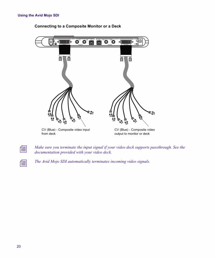
Connecting to a Composite Monitor or a Deck
n Make sure you terminate the input signal if your video deck supports passthrough. See the documentation provided with your video deck.
n The Avid Mojo SDI automatically terminates incoming video signals.
VIDEOAUDIOAUDIO
15VDCOUTPUT3/43/4 1/21/21/21/2
INPUT
VIDEO
HOST
DV
CV (Blue) - Composite video output to monitor or deck
CV (Blue) - Composite video input from deck

Connecting Peripheral Equipment
21
Connecting a Video Deck Using Component Signals
To connect the inputs and outputs of a video deck to the Avid Mojo SDI using component connections, you must use the BNC connectors in the Video Input and Output cables (as well as a customer-supplied cable if needed) that connects as shown in the following illustration and the instructions that follow.
VIDEOAUDIOAUDIO
15VDCOUTPUT3/43/4 1/21/21/21/2
INPUT
VIDEO
HOST
DV
Input — CV (Blue), Y (Green), R-Y (Red) Output — CV (Blue), Y (Green), R-Y (Red)
To video input or output To deck
Customer cable

Using the Avid Mojo SDI
22
To connect a video deck using component signals:
1. Find a customer cable from the deck that connects to the Avid Mojo SDI video and output cables.
2. Attach the ends of that component cable (with the three BNC connectors) to Component cables shown in the preceding illustration:
- Connect the BNC attached to the green wire to the component input connector labeled Y.
- Connect the BNC attached to the red wire to the component input connector labeled Pr.
n The component connectors on your deck might be labeled differently, for example; Y, Cr, and Cb or Y, R-Y, and B-Y.
- Connect the BNC attached to the blue wire to the component input connector labeled Pb.
System Connections and Configurations
As more systems and third-party boards are tested and qualified, and as different configurations are approved, they are placed on the Avid Web site. For the latest information concerning system availability, go to www.Avid.com. Click Products & Services, click your product line (for example, Broadcast), select your Avid application, and then click Specifications.
Connecting the Application Key
The application key (see the following figure), commonly referred to as a dongle, allows the Avid software to run on your system. If you have not yet connected the application key, you must do so before you start the Avid application. If your system has USB ports in the front and in the rear, Avid recommends that you connect the application key to a USB port at the rear of the system.
Application Key

System Connections and Configurations
23
HP xw8200 System Slot Configuration and Connections
Avid has qualified the xw8200 system with the NVIDIA® Quadro® FX 1400/1450 and 3450 graphics board to be used with the Avid Mojo SDI. Other PC systems and graphics boards might be qualified at a later date.
The following table lists the Avid qualified slot configuration for the xw8200 system. The following figure identifies the slots and connections on the rear of the xw8200 system.
c The ATTO™ 3300 and 3305 Fibre Channel boards are designed for 100 MHz PCI-X bus slots. If these Fibre Channel boards are installed into a PCI-X 133 MHz bus slot, you will experience data corruption and data loss. Make sure you install ATTO 3300 or 3305 Fibre Channel board in a PCI-X slot that runs at 100 MHz or less.
HP Workstation xw8200 Slot Assignments
Slot Description
PCI slot 1 (32-bit, 33 MHz, 5 V) Do not use. (This bus segment is used by the integrated 1394 and the integrated Ethernet®.)
n An on-board Ultra 320 SCSI connector panel occupies this location. The on-board SCSI is on the same bus segment as slots 6 and 7.
PCI Express slot 2 (x16 Graphics bus) Qualified OGL graphics board
PCI slot 3 (32-bit, 33 MHz, 5 V) Do not use. (This bus segment is used by the integrated 1394 and the integrated Ethernet.)
PCI Express slot 4 (x8 mechanically, x4 electrically)
Do not use. (PCI-Express is a 2-way serial connection that carries data in packets.) Currently, Avid has not qualified any boards for this slot.
PCI-X slot 5 (64-bit, 133 MHz, 3.3 V) (Option) Avid Unity™ LANshare EX or Avid Unity PortServer gigabit board or second 1394 board. See “Ethernet Support” on page 38 for more Ethernet information. Do not install ATTO 3300/3305 in this slot.
n If you install a second 1394 (FireWire) board, make sure that it is a Universal board. Universal boards can operated at 5 volts and at 3.3 volts.
PCI-X slot 6 (64-bit, 100 MHz, 3.3 V) Available slot
PCI-X slot 7 (64-bit, 100 MHz, 3.3 V) Available slot

Using the Avid Mojo SDI
24
Rear View of xw8200 System
HP xw8000 System Slot Configuration and Connections
Avid has qualified the HP xw8000 system with the NVIDIA Quadro4 1100 XGL graphics board to be used with the Avid Mojo SDI. Other PC systems and graphics boards might be qualified at a later date.
The following table lists the Avid-qualified slot configuration for the xw8000 system. The following figure identifies the slots and connections on the rear of the xw8000 system.
c The ATTO 3300 and 3305 Fibre Channel boards are designed for 100 MHz PCI-X bus slots. If these Fibre Channel boards are installed into a PCI-X 133 MHz bus slot, you will experience data corruption and data loss. Make sure you install ATTO 3300 or 3305 Fibre Channel board in a PCI-X slot that runs at 100 MHz or less.
PS/2 ports
USB portsLAN connection
Video graphics board
PCI Slots
MicrophoneLine OUT
Line IN
Channel A SCSI connector
Serial portParallel port
Channel B SCSI connector
1234567
1394 6-pin connection

System Connections and Configurations
25
Rear View of xw8000 System
HP Workstation xw8000 Slot Assignments
Slot Description
AGP slot Qualified OGL graphics board
PCI slot 1 (32-bit, 33 MHz, 5 V) Do not use. (This bus segment is used by the integrated 1394 and the integrated Ethernet.)
PCI slot 2 (32-bit, 33 MHz, 5 V) Do not use. (This bus segment is used by the integrated 1394 and the integrated Ethernet.)
PCI-X slot 3 (64-bit, 133 MHz, 3.3 V) (Option) Avid Unity LANshare EX or Avid Unity PortServer gigabit board or second 1394 board. See “Ethernet Support” on page 38 for more Ethernet information.
c Do not install the ATTO 3300 or 3305 Fibre Channel board in this slot.
n If you install a second 1394 (FireWire) board, make sure that it is a Universal board. Universal boards can operated at 5 volts and at 3.3 volts.
PCI-X slot 4 (64-bit, 100 MHz, 3.3 V) Available slot
PCI-X slot 5 (64-bit, 100 MHz, 3.3 V) (Option for Avid NewsCutter® XP) Fibre Channel board to Avid Unity system or Fibre Channel board to playback device
Keyboard and mouse
USB ports
LAN connection
AGP Slot
PCI Slots
MicrophoneLine OUT
Line IN
Channel A SCSI connector
Serial portParallel port
Channel B SCSI connector
12345
1394 6-pin connection

Using the Avid Mojo SDI
26
Macintosh Dual Quad Core G5 System
The following table and figure identifies the slots and connections on the rear of the Macintosh Dual/Quad core G5 system.
Rear View of G5 System
Dual/Quad Core G5 Slot Assignments
Slot Description
PCI-Express 4X slot 4 (Option) Atto ExpressPCIe UL5D SCSI
PCI-Express 8X slot 3 (Option) Atto Celerity FC-42ES
PCI-Express 4X slot 2 Not used at this time.
PCI Express 16X graphics board graphics board
Slot 1 PCI Express 16X graphics board
USB ports
Dual Gigabit Ethernet connections
Audio connections
FireWire 400, 6-pin connection
FireWire 800, 9-pin connection (1394B)
Slot 2 PCI Express 4X
Slot 4 PCI Express 4X
Slot 3 PCI Express 8X

System Connections and Configurations
27
Macintosh G5 System Slot Configuration and Connections
The following table lists the Avid qualified slot configuration for the Macintosh G5 system. The following figure identifies the slots and connections on the rear of the Macintosh G5 system.
Rear View of G5 System
G5 Slot Assignments
Slot Description
PCI-X slot 4 (64-bit, 133 MHz, 3.3 V) (Option) Second 1394 FireWire board or Ultra320 SCSI (UL4D) board
PCI-X slot 3 (64-bit, 100 MHz, 3.3 V) (Option) Fibre Channel board to Avid Unity system
PCI-X slot 2 (64-bit, 100 MHz, 3.3 V) (Option) Ultra160 SCSI (UL3D) board or second 1394 FireWire board when an Ultra320 SCSI board is used in slot 4
AGP slot Apple® graphics board
Slot 4
Slot 1 Apple graphics board
USB ports
Ethernet connection
Audio connections
FireWire 400, 6-pin connection
FireWire 800, 9-pin connection (1394B)
Modem connection

Using the Avid Mojo SDI
28
Macintosh G4 System Slot Configuration and Connections
Avid has qualified the G4 system with the NVIDIA GeForce™4 Titanium graphics board to be used with the Avid Mojo SDI. Other Macintosh systems and graphics boards might be qualified at a later date.
The following table lists the Avid qualified slot configuration for the Macintosh G4 system. The following figure identifies the slots and connections on the rear of the Macintosh G4 system.
Rear View of G4 System
G4 Slot Assignments
Slot Description
PCI slot 5 (64-bit, 33 MHz, 5 V) Available slot
PCI slot 4 (64-bit, 33 MHz, 5 V) (Option) Avid Unity LANshare EX or Avid Unity PortServer gigabit board or second 1394 FireWire board
PCI slot 3 (64-bit, 33 MHz, 5 V) (Option) SCSI UL3D or Fibre Channel board to Avid Unity system
PCI slot 2 (64-bit, 33 MHz, 5 V) (Option) SCSI UL3D or Fibre Channel board to Avid Unity system
AGP slot 1 Apple graphics board
5
4
3
2
1
Slot 5
Slot 1 Apple graphics board
USB ports
FireWire 6-pin connections
Audio connections

Connecting Serial and MIDI Port Devices
29
Connecting Serial and MIDI Port Devices
Avid systems support the connection of two different MIDI fader controllers and a Yamaha® 01V mixer. The fader controllers and the 01V mixer connect to the MIDISPORT™ 2x2 USB-to-MIDI converter attached to the USB ports. The two fader controllers are the JL Cooper FaderMaster Pro™ and the JL Cooper MCS-3000X™. Avid supports recording automation gain using the MIDI features of the 01V mixer. This section contains:
• USB and Serial Differences Between Windows and Macintosh Systems
• USB and Serial Connections (Windows Only)
• Connecting the USB Hub
• Connecting the USB Devices to the USB Hub
• Connecting JL Cooper Fader Controllers
• Connecting the Yamaha 01V Mixer
• Connecting the Yamaha 01V/96 Mixer
• Controlling a Video Deck
USB and Serial Differences Between Windows and Macintosh Systems
If you have a Windows system, you likely have 2 or more USB connections and one serial connection. If you need more than one serial connection, Avid recommends using a USB-to-serial adapter. See the documentation that comes with the device.
If you have a Macintosh system, you might have two USB connectors and no serial ports. Avid suggests you attach a USB hub to the rear of the system and use a Keyspan Twin USB-to-serial adapter for deck control.
USB and Serial Connections (Windows Only)
Windows systems typically have two or more USB connections and one serial connection. If you need more than one serial connection, Avid recommends using a USB-to-serial adapter. See the documentation that comes with the device.

Using the Avid Mojo SDI
30
Connecting the USB Hub
The USB hub explained in this section converts one USB port into seven USB ports. The USB hub kit (see the following figure) contains a USB hub, a power adapter, and a USB cable.
n The USB hub shown in the example might not be the actual USB hub you use. However, the example shown provides enough information to allow you to properly connect whichever USB hub you decide to use.
n The USB hub is supported only when it is powered by an ac adapter.
The USB hub has the following connections:
• USB ports 1 through 7
• Device connection
• On/Off switch
• Power connection
USB Hub
Power connection
USB hub
DC connector AC power adapter
USB cable
USB connector
USB ports
Device connection
On/Off switch
Device connector

Connecting Serial and MIDI Port Devices
31
To connect the USB hub:
1. Connect the power adapter to the USB hub:
a. Plug the dc connector of the ac power adapter into the USB hub power connection.
b. Plug the ac power adapter into a wall outlet or power strip.
2. Connect the USB hub to the system using the USB cable:
a. Plug the device connector of the USB cable into the device connection at the rear of the USB hub.
b. Plug the USB connector of the USB cable into one of the USB ports at the rear of the system.
3. Turn on the power.
Connecting the USB Devices to the USB Hub
Once the USB hub is connected to the system, you can connect the following USB devices to the USB hub:
• USB-to-serial adapter
• USB-to-MIDI converter
Connecting the USB-to-Serial Adapter
The USB-to-serial adapter connects to a USB port on the USB hub (see the following figure).
USB-to-Serial Adapter
USB-to-serial adapter cable

Using the Avid Mojo SDI
32
To connect the USB-to-serial adapter to the USB hub:
1. Plug the USB-to-serial adapter cable into a USB port on the USB hub (see “Connecting the USB Hub” on page 30 for port locations).
2. Install the USB-to-serial adapter software, using the instructions that came with the USB-to-serial adapter.
Connecting the USB-to-MIDI Converter
Avid recommends the use of the MIDISPORT 2x2 USB-to-MIDI converter connected to a USB hub for the Macintosh systems or to a USB port on a PC (see the following figure).
Connecting the USB-to-MIDI Converter
n The ReadMe file and the Help in your application explain how to install the drivers and configure the USB-to-MIDI converter.
To connect the USB-to-MIDI converter to a port on the USB hub:
1. Locate the MIDI converter USB cable.
2. Connect the device connector of the USB cable to the device connector on the USB-to-MIDI converter.
3. Connect the other end of the USB cable to a USB port on the USB hub (see “USB Hub” on page 30 for a port location).
4. Push the USB/MIDI Thru button in to allow the device to function as a USB-to-MIDI converter (see the following figure).
USB-to-MIDI Converter Front Panel
USB connector
USB-to-MIDI converter USB cable
Device connector Device connector
IN A
IN A IN B
OUT A OUT B
USB/MIDIThru
USB
Button (In position)

Connecting Serial and MIDI Port Devices
33
Connecting JL Cooper Fader Controllers
Your Avid system supports the FaderMaster Pro and the MCS-3000X fader controllers. Both of the fader controllers connect to a USB-to-MIDI converter that connects to a USB port on the system. See your Avid editing application Help to initialize your JL Cooper fader controllers.
Fader controller connections are shown for both the MCS-3000X and the FaderMaster Pro (see the following figures). There are two major differences between the two fader controllers:
• The MCS-3000X has a four-position switchpack that is not on the FaderMaster Pro.
• The MIDI IN and MIDI OUT are in opposite positions in the MCS-3000X and the FaderMaster Pro.
To connect the fader controllers:
1. Quit any open applications.
2. Shut down the Avid editing system.
3. Make sure your USB-to-MIDI converter is connected to the USB port as explained in “Connecting the USB-to-MIDI Converter” on page 32.
4. If you are cabling the MCS-3000X, set switch 4 to the ON (down) following figure).
5. Locate two MIDI cables with 5-pin DIN connectors.
n You can use the In A and Out A connector pair or the In B and Out B connector pair on the rear of the USB-to-MIDI converter. Whichever pair you use, select the corresponding port when you configure the device using the Controller Settings dialog box in the Avid editing application. For information on configuring the device, see “Using the FaderMaster Pro and MCS-3000X” in the Help.
6. Plug one end of the first MIDI cable into the In A connector of the USB-to-MIDI converter (see “Connecting the USB-to-MIDI Converter” on page 32), and the other end of the cable into the MIDI OUT connector of the fader controller.
7. Plug one end of the second MIDI cable into the Out A connector of the USB-to-MIDI converter, and the other end of the cable into the MIDI IN connector of the fader controller.
8. Make sure the button on the front of the USB-to-MIDI converter is pushed in (see “Connecting the USB-to-MIDI Converter” on page 32).

Using the Avid Mojo SDI
34
JL Cooper MCS-3000X Fader Controller Cabling
JL Cooper FaderMaster Pro Fader Controller Cabling
USB-to-MIDI Converter Front Panel
MIDI OUT MIDI INSELECT
POWER
ONEXPANDER
1234
CTS 206-4
ON
In B Out BOut A
USB-to-MIDI converter (rear)
MIDI cable
Switch
MIDI OUT
MIDI IN
MIDI cable to In A (see “USB-to-MIDI Converter Front Panel” on page 34)
Out A
Power 9VDC MIDI In MIDI Out Switch In Switch Out
+_
In B Out BOut A
USB-to-MIDI converter (rear)
MIDI cable
Out AMIDI OUT
MIDI IN
MIDI cable to In A (see “USB-to-MIDI Converter Front Panel” on page 34)
IN A
IN A IN B
OUT A OUT B
USB/MIDIThru
USB
Button (In position)
In A

Connecting Serial and MIDI Port Devices
35
Connecting the Yamaha 01V Mixer
To connect the 01V mixer:
1. Quit any open applications.
2. Shut down the Avid editing system.
3. Make sure your USB-to-MIDI converter is connected to the USB port as explained in “Connecting the USB-to-MIDI Converter” on page 32.
4. Locate two MIDI cables with 5-pin DIN connectors.
n You can use the In A and Out A connector pair or the In B and Out B connector pair on the rear of the USB-to-MIDI converter. Whichever pair you use, select the corresponding port when you configure the device using the Controller Settings dialog box in the Avid editing application. For information on configuring the device, see “Using the FaderMaster Pro and MCS-3000X” in the Help.
5. Plug one end of the first MIDI cable into the In A connector of the USB-to-MIDI converter (see “USB-to-MIDI Converter Front Panel” on page 34).
6. Plug the other end of the cable into the MIDI OUT connector of the 01V mixer (see the following figure).
7. Plug one end of the second MIDI cable into the Out A connector of the USB-to-MIDI converter.
8. Plug the other end of the cable into the MIDI IN connector of the 01V mixer (see the following figure).
9. Make sure button on the front of the USB-to-MIDI converter is pushed in (see “USB-to-MIDI Converter Front Panel” on page 34).
Yamaha 01V Mixer Rear View
n You must set up the 01V mixer using its front panel. See your Avid editing application Help for more setup instructions.
MONITOR OUTSREREO OUT
DIGITAL STEREOOMNI OUT
COAXIALMIDI TO HOST
ININOUT OUTTHRU
R L
R L
4 3 2 1
POWEROPTION 1/0
ON OFF
In B Out BOut A
USB-to-MIDI converter (rear)
Out A
MIDI OUT MIDI IN
MIDI cable to In A (see “USB-to-MIDI Converter Front Panel” on page 34)

Using the Avid Mojo SDI
36
n The Yamaha 01V mixer can also be connected directly to a serial port. For information on configuring the mixer when connected to a serial port, see “Setting up the Yamaha 01V/96 or Yamaha 01V” in the Help.
Connecting the Yamaha 01V/96 Mixer
You can connect a Yamaha 01V/96 mixer via MIDI using the same procedure described in “Connecting the Yamaha 01V Mixer” on page 35. However, Avid recommends that you use a USB connection for this mixer. For information on connecting the Yamaha 01V/96, see “Setting up the Yamaha 01V/96 or Yamaha 01V” in the Help.
Controlling a Video Deck
Avid editing systems provide video deck control through a serial control connector on most analog decks. You can control a single deck by using an RS-232 to RS-422 serial adapter. An optional RS-232 to RS-422 serial adapter kit is available through Avid.
The optional serial adapter kit that contains the following:
• An RS-232 to RS-422 serial adapter
• Two serial cables with 9-pin male connectors at both ends
To connect a single deck to your system:
1. Locate the serial adapter kit.
2. Attach one end of a 9-pin cable to the end of the serial adapter labeled RS-232.
3. Attach the other end of the 9-pin cable to the serial port on the Avid editing system (see the following figure) or to the serial connector of the USB-to-serial adapter.
n When you attach the cable to the serial port on the PC, note if you are using the COM1 or COM2 serial port. You need to select the same port in the Avid editing application.
Video Deck Control Cabling
To video deck
RS-422 connection RS-232 connection
To Avid editing system
Serial Adapter

Storage
37
4. Attach one end of another 9-pin cable to the end of the serial adapter labeled RS-422.
5. Attach the other end of the 9-pin cable to the remote serial port of the video deck.
n Place the deck in Remote mode before attempting to control the deck using the software. See the documentation provided with your deck.
Storage
You have several storage options, including SCSI, Fibre Channel, 1394, and Ethernet. To use all the resolutions available in your Avid editing application, you might need to configure and stripe your drives. Storage options are explained in the following sections.
SCSI Support
Avid has qualified the two SCSI channels on the rear of the HP xw8200 and HP xw8000 systems (see “HP xw8200 System Slot Configuration and Connections” on page 23 and “HP xw8000 System Slot Configuration and Connections” on page 24). The channels connect to dual U320 SCSI ports on the system board. You can use the two SCSI connectors at the rear of the system and a Fibre Channel board in the HP xw8200 and HP xw8000 systems at the same time.
Avid supports the ATTO SCSI UL3D/160 LVD board in the G4 system and the G5 system. Additional boards might be supported at a later date. You can use a SCSI board and a Fibre Channel board at the same time in the G4 system or the G5 system.
Documentation for connecting storage devices is included with the devices on a CD-ROM if they are purchased from Avid. Striping information can be found on the Avid Knowledge Base.
n Contact your Avid Sales and Product information line at 800-949-2843 for the latest storage product information.

Using the Avid Mojo SDI
38
1394 Support
When you are using an Avid Mojo SDI and you want to use 1394 (FireWire) drives, you need a second 1394 OHCI board on a different bus segment in your Avid editing system. See your computer manufacturer’s documentation to identify a PCI bus slot that is on a different bus segment than the 1394 port used for the Avid Mojo SDI.
n If you use a 1394 board in slots 3, 4, or 5 (PCI-X slots) in the xw8000 it must be a “universal” PCI card and not a +5V-only board.
To determine the supported 1394 boards, go to www.avid.com. Click Products & Services, click your product line (for example, Broadcast), select your Avid application, and then click Specifications.
n At this time, Avid has not qualified a FireWire 800 (or 1394b) drive to be used with Avid Mojo SDI systems. For the latest qualified storage products, contact your local Avid Reseller or call the Avid Sales and Product information line at 800-949-2843 for the latest information about available drives.
Internal IDE Drives
An internal IDE drive can be used for media storage with your Avid Mojo SDI.
Ethernet Support
At this time only the Alacritech® 1-Gb board is supported. For supported devices and configurations, go to www.avid.com. Click Products & Services, click your product line (for example, Broadcast), select your Avid application, and then click Specifications.
n You cannot use the built-in 1394 connection and the built-in 1-Gb Ethernet for an Avid LANshare EX connection in the HP xw8200 and HP xw8000 systems at the same time.
Fibre Channel Support
Avid provides support for local storage using the following Fibre Channel boards in the xw8000 system, G4 system, and G5 system:
• ATTO 2-Gb optical Fibre Channel (Model 3300, single channel)
• ATTO 2-Gb copper Fibre Channel (Model 3305, single channel)
Avid has also qualified the NewsCutter XP as a Fibre Channel client on an Avid Unity MediaNetwork.

Storage
39
Formatting and Striping Media Drives (Windows)
To use all the resolutions available in your Avid editing application, you might need to stripe your media drives. Disk drives must be configured as Dynamic if you are striping drives.
To configure and stripe a drive:
1. Start your system, and log into an account with administrative privileges.
2. Right-click the My Computer icon, and select Manage.
The Computer Management window opens.
3. Click the Disk Management folder.
n For more information on the Computer Management window, click the Help icon in the toolbar of the Computer Management window.
4. Make a drive Dynamic by right-clicking the disk ID section of the disk in the Computer Management window and selecting Upgrade to Dynamic disk, or Create Dynamic disk, depending upon the status of your disk.
When you select a disk in the Computer Management window, the white section of the disk changes to stripes, showing that the section has been selected.
5. Repeat step 4 for each drive you want to stripe.
6. Right-click one of the Dynamic drives and select Action > Create Volume.
7. Follow the instructions in the Create Volume Wizard to finish striping the drives using NTFS format.
Formatting and Striping MediaDrives (Macintosh)
To use all the resolutions available in your Avid editing system, use the ATTO ExpressStripe software to stripe drives on the Mac OS® X operating system. The ExpressStripe software is installed in the following location:
/Applications/ExpressStripe
The instructions for using the software are in a PDF file, Expressstripe.pdf, that is installed along with the ExpressStripe application.
n You must be logged in as an Administrator to stripe drives.
c Do not use the Apple Disk Utility application (in Applications/Utilities) to stripe drives. If you use the Disk Utility application, you cannot view the drives on the Mac OS 9 system. Additionally, Avid’s drive filtering feature does not function properly, resulting in poor performance.

Using the Avid Mojo SDI
40
Using Striped Drives on Mac OS X and Mac OS 9.x Systems
The Avid editing software automatically recognizes drives that were striped on Mac OS 9.x. You should be able to use these drives to edit and play video. However, if you move a drive that was striped on a Mac OS X system back to Mac OS 9.x, you cannot play video from the drives on Mac OS 9.x. If necessary, you can set up your Mac OS 9.x system so that it recognizes the drives. You can then copy media files from the drive to your Mac OS 9.x drives.
To set up a Mac OS 9.x system to recognize drives that were striped on a Mac OS X system:
1. Navigate to the following folder:
Applications/Avid Goodies/OS 9/System Folder/Extensions
2. Copy the file ~~ExpressStripe_OS9_Enablr to the Extensions folder on your Mac OS 9 system.
3. Restart the Mac OS 9 system.
The system is now able to recognize the striped drives. You can use the drives to copy media onto your Mac OS 9 drives.
c Do not run a Mac OS 9 version of your Avid editing application on the same system as a Mac OS X version of your Avid editing system. There might be conflicts between the system files used by the two applications.
Moving Striped Drives to Another System (Macintosh Only)
In order to move striped drives to another system, you need to be able to identify the drives that make up a particular striped set. This was easy on Mac OS 9 because the system allowed you to use the SCSI ID order when striping drives.
On Mac OS X, the system does not use the SCSI ID but instead uses its internal diskn name (where n is the drive number) when creating the striped sets. You can use Avid Storage Manager or ExpressStripe to identify a striped set on Mac OS X.
To use Avid Storage Manager to identify a striped set:
1. Start the Avid Storage Manager application and select View > Volumes.
2. Select the striped volume you want to move and click Identify.
The system blinks the lights on the front of the drives that make up the volume.

Specifications
41
To use ExpressStripe to identify a striped set:
1. Start the ExpressStripe application.
2. In the opening dialog boxes, select Utilities and then select Benchmark.
3. Select the striped volume you want to move and click Start.
The system runs the benchmark test on the volume and shows activity on the front of the drives that make up the volume.
Specifications
The following information provides specifications for the Avid Mojo SDI.
Dimensions and Weight
The following table shows the dimensions and weight for the Avid Mojo SDI enclosure. The dimensions are based on the unit in the stand; the orientation is shown in “Avid Mojo SDI Front and Rear Panels” on page 7.
Dimensions and Weight
Dimension Avid Mojo SDI Stand
Width 1.13 in (28.7 mm) 4.5 in (114.3 mm)
Height 11.0 in (279.4 mm) 2.13 in (54.1 mm)
Depth 6.8 in (172.7 mm) 8.5 in (215.9 mm)
Weight 1.5 lb (0.68 kg) 1.32 lb (0.59 kg)

Using the Avid Mojo SDI
42
Environmental Specifications
The following table shows the environmental specifications for the Avid Mojo SDI enclosure.
Electrical Specifications
The following table shows electrical specifications for the power adapter used to power the Avid Mojo SDI enclosure.
Environmental Specifications
Environment Specification
Ambient room temperature (Maximum) 95°F (35°C)
Operating humidity 5% to 90% noncondensing
Storage temperature –40°F to 158°F (–40°C to 70°C)
Storage humidity 5% to 95% noncondensing
Electrical Specifications for Power Adapter
Topic Specification
Voltage
Input range
Output
90 V ac to 240 V ac
9 V dc
Frequency range 47 Hz to 63 Hz
Current
ac input
dc output
0.7 a for 115 V ac0.4 a for 230 V ac
2.23 a
Watts 20 w

Regulatory and Safety Notices
43
Regulatory and Safety Notices
The following sections explain the regulatory and safety notices for the Avid Mojo.
Warnings and Cautions
w Never install equipment if it appears damaged.
w Disconnect the power cord before servicing unit.
w Only perform the services explicitly described in this document. For services or procedures not outlined in this document, speak with authorized Avid service personnel.
c Follow all warnings and cautions in the procedures.
c Operate the device within its marked electrical ratings and product usage instructions.
FCC Notice
This device complies with Part 15 of the FCC Rules. Operation is subject to the following two conditions:
1. This device may not cause harmful interference.
2. This device must accept any interference received, including interference that may cause undesired operation.
This equipment has been tested and found to comply with the limits for a Class A digital device, pursuant to Part 15 of the FCC Rules. These limits are designed to provide reasonable protection against harmful interference when the equipment is operated in a commercial environment. This equipment generates, uses, and can radiate radio frequency energy and, if not installed in accordance with the instruction manual, may cause harmful interference to radio communications. Operation of this equipment in a residential area is likely to cause harmful interference in which case the user will be required to correct the interference at his own expense.

Using the Avid Mojo SDI
44
Canadian ICES-003
This Class A digital apparatus meets all requirements of the Canadian Interference Causing Equipment Regulations.
Cet appareil numérique de la classe A respecte toutes les exigences du Règlement sur le matériel brouilleur du Canada.
European Union Notice
Declaration of Conformity (According to ISO/IEC Guide 22 and EN 45014)
Application of Council Directives:
73/23/EEC, 89/336/EEC.
Standards to which Conformity is Declared:
EN60950:2000 Third EditionCISPR 22:1997 / EN55022:1994 + A1:1995 + A2:1997 Class Aa EN55024:1998/EN61000 — 3-2, 4-2, 4-3, 4-4, 4-5, 4-6, 4-8, 4-11, 3-3
Manufacturer’s Name:
Avid Technology, Inc. 1925 Andover StreetTewksbury, MA 01876, USA
European Contact: Nearest Avid Sales and Service Office or Avid Technology International B.V. Sandyford Business Center Unit 3,Dublin 18, Ireland
Type of Equipment: Information Technology Equipment

FCC Notice
45
Product Name: Products for the Windows NT, Windows 2000, or Windows XP Operating System: Avid Adrenaline DNA, Avid DS Nitris DNA, Avid Equinox Break-Out-Box, Avid|DS, Avid Xpress, Avid Xpress DV, Film Composer, Media Composer, MediaDock, MediaDock 2+, MediaDrive, MediaRAID, MEDIArray, MEDIArray Drive, MEDIArray II, MEDIArray II Drive, Meridien I/O box, NewsCutter, NewsCutter DV, NewsCutter XP, Pro Tools AVoption|V10, Symphony
Products for the Mac OS X Operating System: Avid Adrenaline DNA, Avid Xpress, Avid Xpress DV, Film Composer, Media Composer, MediaDock, MediaDock 2+, MediaDrive, MediaRAID, MEDIArray, MEDIArray Drive, MEDIArray II, MEDIArray II Drive, Meridien I/O box, Pro Tools AVoption|V10, Symphony
Products for the UNIX Operating System: AirPlay, AirSPACE, AirSpeed, VideoSPACE
Products for MediaNetwork and Workgroups: Avid ProEncode, Avid Unity MediaManager, Avid Unity MediaNetwork (includes File Manager), Avid Unity TransferManager, LANserver, LANserver EX, MEDIArray, MEDIArray Drive, MEDIArray II, MEDIArray II Drive, MEDIArray ZX, MEDIArray ZX Drive, Nearchive, PortServer, Vixel switches (8100, 7100, 7200, 9100, 9200), Xdeck
Base Model Numbers: None
Product Options: All
Year of Manufacture: 2006
a. This is class A product. In a domestic environment this product may cause radio interference, in which case the user may be required to take adequate measures.

Using the Avid Mojo SDI
46
(1) Products for the Windows NT, Windows 2000, or Windows XP Operating System: products were tested in a typical Avid Adrenaline DNA, Avid DS Nitris DNA, Avid Equinox Break-Out-Box, Avid|DS, Avid Xpress, Avid Xpress DV, Film Composer, Media Composer, MediaDock, MediaDock 2+, MediaDrive, MediaRAID, MEDIArray, MEDIArray Drive, MEDIArray II, MEDIArray II Drive, Meridien I/O box, NewsCutter, NewsCutter DV, NewsCutter XP, Pro Tools AVoption|V10, or Symphony configuration.
(2) Products for the Mac OS X Operating System: products were tested in a typical Avid Adrenaline DNA, Avid Xpress, Avid Xpress DV, Film Composer, Media Composer, MediaDock, MediaDock 2+, MediaDrive, MediaRAID, MEDIArray, MEDIArray Drive, MEDIArray II, MEDIArray II Drive, Meridien I/O box, Pro Tools AVoption|V10, or Symphony configuration.
(3) Products for the UNIX Operating System: products were tested in an AirPlay, AirSpeed, or VideoSPACE configuration.
(4) Products for MediaNetwork and Workgroups: products were tested in a typical Avid ProEncode, Avid Unity MediaManager, Avid Unity MediaNetwork (includes File Manager), Avid Unity TransferManager, LANserver, LANserver EX, MEDIArray, MEDIArray Drive, MEDIArray II, MEDIArray II Drive, MEDIArray ZX, MEDIArray ZX Drive, Nearchive, PortServer, or Xdeck configuration.
I, the undersigned, hereby declare that the equipment specified above conforms to the above Directives and Standards.
Dave Perri, Director of Hardware Engineering
Australia and New Zealand EMC Regulations
Nigel Streatfield, General ManagerAvid Technology (Australia)Unit B5 Skyline PlaceFrenchs Forest NSW 2086AustraliaPhone: 61-2-8977-4800
N1709

Technical Support Information
47
Technical Support Information
Most products feature a number of coverage options. Avid Assurance service offerings are designed to facilitate your use of Avid solutions. Service options include extended telephone coverage, automatic software maintenance, extended hardware warranty, and preferred pricing on replacement parts.
For more information regarding Avid’s service offerings, visit www.avid.com/support or call Avid Sales at 800-949-AVID (800-949-2843).
Program availability and details might vary depending on geographic location and are subject to change without notice. Contact your local Avid office or your local Avid Reseller for complete program information and pricing. However, if you need help locating an Avid office or Avid Reseller near you, please visit www.avid.com or call in North America 800-949-AVID (800-949-2843). International users call 978-275-2480.

Using the Avid Mojo SDI
48
Copyright and DisclaimerProduct specifications are subject to change without notice and do not represent a commitment on the part of Avid Technology, Inc.
The software described in this document is furnished under a license agreement. You can obtain a copy of that license by visiting Avid's Web site at www.avid.com. The terms of that license are also available in the product in the same directory as the software. The software may not be reverse assembled and may be used or copied only in accordance with the terms of the license agreement. It is against the law to copy the software on any medium except as specifically allowed in the license agreement.
Avid products or portions thereof are protected by one or more of the following United States patents: 4,746,994; 4,970,663; 5,045,940; 5,267,351; 5,309,528; 5,355,450; 5,396,594; 5,440,348; 5,452,378; 5,467,288; 5,513,375; 5,528,310; 5,557,423; 5,568,275; 5,577,190; 5,583,496; 5,584,006; 5,627,765; 5,640,601; 5,644,364; 5,654,737; 5,715,018; 5,719,570; 5,724,605; 5,726,717; 5,729,673; 5,745,637; 5,752,029; 5,754,851; 5,799,150; 5,812,216; 5,828,678; 5,842,014; 5,852,435; 5,905,841; 5,929,836; 5,930,445; 5,946,445; 5,987,501; 5,999,406; 6,016,152; 6,018,337; 6,023,531; 6,038,573; 6,058,236; 6,061,758; 6,091,778; 6,105,083; 6,118,444; 6,128,001; 6,134,607; 6,137,919; 6,141,007; 6,141,691; 6,198,477; 6,201,531; 6,211,869; 6,223,211; 6,249,280; 6,269,195; 6,317,158; 6,317,515; 6,330,369; 6,351,557; 6,353,862; 6,357,047; 6,392,710; 6,404,435; 6,407,775; 6,417,891; 6,426,778; 6,477,271; 6,489,969; 6,512,522; 6,532,043; 6,546,190; 6,552,731; 6,553,142; 6,570,624; 6,571,255; 6,583,824; 6,596,031; 6,618,547; 6,636,869; 6,665,450; 6,678,461; 6,687,407; 6,704,445; 6,747,705; 6,763,134; 6,763,523; 6,766,063; 6,766,357; 6,791,556; 6,810,157; 6,813,622; 6,847,373; 6,871,003; 6,871,161; D352,278; D372,478; D373,778; D392,267; D392,268; D392,269; D395,291; D396,853; D398,912. Other patents are pending.
No part of this document may be reproduced or transmitted in any form or by any means, electronic or mechanical, including photocopying and recording, for any purpose without the express written permission of Avid Technology, Inc.
Copyright © 2006 Avid Technology, Inc. and its licensors. All rights reserved.
Attn. Government User(s). Restricted Rights LegendU.S. GOVERNMENT RESTRICTED RIGHTS. This Software and its documentation are “commercial computer software” or “commercial computer software documentation.” In the event that such Software or documentation is acquired by or on behalf of a unit or agency of the U.S. Government, all rights with respect to this Software and documentation are subject to the terms of the License Agreement, pursuant to FAR §12.212(a) and/or DFARS §227.7202-1(a), as applicable.
Trademarks888 I/O, Adrenaline, AirPlay, AirSPACE, AirSPACE HD, AirSpeed, AniMatte, AudioSuite, AudioVision, AutoSync, Avid, Avid DNA, Avid DNxcel, Avid DNxHD, AVIDdrive, AVIDdrive Towers, Avid Mojo, AvidNet, AvidNetwork, AVIDstripe, Avid Unity, Avid Xpress, AVoption, AVX, CamCutter, ChromaCurve, ChromaWheel, DAE, D-Fi, D-fx, Digidesign, Digidesign Audio Engine, Digidesign Intelligent Noise Reduction, DigiDrive, Digital Nonlinear Accelerator, DigiTranslator, DINR, D-Verb, Equinox, ExpertRender, FieldPak, Film Composer, FilmScribe, FluidMotion, HIIP, HyperSPACE, HyperSPACE HDCAM, IllusionFX, Image Independence, Intraframe, iS9, iS18, iS23, iS36, LaunchPad, Lo-Fi, Magic Mask, make manage move | media, Marquee, Matador, Maxim, MCXpress, Media Composer, MediaDock, MediaDock Shuttle, Media Fusion, Media Illusion, MediaLog, Media Reader, Media Recorder, MEDIArray, MediaShare, Meridien, MetaSync, MissionControl, NaturalMatch, Nearchive, NetReview, NewsCutter, Nitris, OMF, OMF Interchange, OMM, Open Media Framework, Open Media Management, ProEncode, Pro Tools, QuietDrive, Recti-Fi, RetroLoop, rS9, rS18, Sci-Fi, Softimage, Sound Designer II, SPACE, SPACEShift, SpectraGraph, SpectraMatte, Symphony, Trilligent, UnityRAID, Vari-Fi, Video Slave Driver, VideoSPACE, and Xdeck are either registered trademarks or trademarks of Avid Technology, Inc. in the United States and/or other countries.
iNEWS, iNEWS ControlAir, and Media Browse are trademarks of iNews, LLC.
Alacritech is a registered trademark of Alacritech, Inc. Apple, PowerBook, FireWire, Macintosh, and Mac OS are trademarks of Apple Computer, Inc., registered in the U.S. and other countries. ATTO is a trademark of ATTO Technology, Inc. FaderMaster Pro is a trademark of JL Cooper, a division of Sound Technology. GeForce, NVIDIA, and Quadro are registered trademarks or trademarks of NVIDIA Corporation in the United States and/or other countries. HP is a registered trademark of Hewlett-Packard Company. PowerPC is a registered trademark of International Business Machines Corporation, used under license therefrom. MIDISPORT is a trademark of M-AUDIO. RCA is a registered trademark of General Electric Company. VLXi is a registered trademark of Videomedia, Inc. Windows is either a registered trademark or trademark of Microsoft Corporation in the United States and/or other countries. Yamaha is a registered trademark of Yamaha Corporation of America. All other trademarks contained herein are the property of their respective owners.
Using the Avid Mojo SDI • Part 0130-07556-01 Rev. A • June 2006