User’s Manual - Coding and Labelling Systems from … the user's authority to operate the...
45
User’s Manual EZPi-1000 Series P/N. 920-013011-01 Rev. A, 08.2009
Transcript of User’s Manual - Coding and Labelling Systems from … the user's authority to operate the...
User’s Manual
EZPi-1000 Series
P/N. 920-013011-01 Rev. A, 08.2009

FCC COMPLIANCE STATEMENT FOR AMERICAN USERS
This equipment has been tested and found to comply with the limits for a CLASS A digital device, pursuant to Part 15 of the FCC Rules. These limits are designed to provide reasonable protection against harmful interference when the equipment is operated in a commercial environment. This equipment generates, uses, and can radiate radio frequency energy and, if not installed and used in accordance with the instructions, may cause harmful interference to radio communications. Operation of this equipment in a residential area is likely to cause harmful interference in which case the user will be required to correct the interference at own expense.
EMS AND EMI COMPLIANCE STATEMENT FOR EUROPEAN USERS
This equipment has been tested and passed with the requirements relating to electromagnetic compatibility based on the standards EN 55022:1998+A1:2000+A2:2003, CISPR 22 , Class A EN 55024:1998+A1:2001+A2:2003, IEC 61000- 4 Series EN 61000-3-2 / 2000 & EN 61000-3-3 / 1995. The equipment also tested and passed in accordance with the European Standard EN55022 for the both Radiated and Conducted emissions limits.
EZPi-1000 SERIES TO WHICH THIS DECLARATION RELATES
IS IN CONFORMITY WITH THE FOLLOWING STANDARDS EN55022 : 1998,CLSPR 22, Class A / EN55024 : 1998IEC 61000-4 Serial / EN61000-3-2 : 2000 / EN 6100-3-3 : 1995 / CFR 47, Part 15/CISPR 22 3rd Edition : 1997, Class A / ANSI C63.4 : 2001 / CNS 13438 / IEC60950-1 : 2001 / GB4943 : 2001 / GB9254 : 1998 / GB17625.1 : 2003 /EN60950-1 : 2001
CAUTION Danger of explosion if battery is incorrectly replaced Replace only with the equivalent type recommended by the manufacture. Dispose of used batteries according to the manufacturer’s instructions. Only use with power supply adapter model: WDS060240P (9A). Changes or modifications not expressly approved by the party responsible for compliance could void the user's authority to operate the equipment.
Specifications are subject to change without notice.
EZPi-1000 User’s Manual
1

Safety Instructions
Bitte die Sicherheitshinweise sorgfältig lesen und für später aufheben.
1. Die Geräte nicht der Feuchtigkeit aussetzen.
2. Bevor Sie die Geräte ans Stromnetz anschließen, vergewissern Sie Sich, dass die
Spannung des Geräts mit der Netzspannung übereinstimmt.
3. Nehmen Sie das Gerät bei Überspannungen (Gewitter) vom Netz. Das Gerät könnte
sonst Schaden nehmen.
4. Sollte versehentlich Flüssigkeit in das Gerät gelangen, so ziehen sofort den
Netzstecker. Anderenfalls besteht die Gefahr eines lebensgefährlichen elektrischen
Schlags.
5. Wartungs- und Reparaturarbeiten dürfen aus Sicherheitsgründen nur von
autorisierten Personen durchgeführt werden.
6. Bei Wartungs- und Reparaturarbeiten müssen die Sicherheitsvorschriften der
zuständigen Berufsverbände und Behörden unbedingt eingehalten werden.
7. Bei Verletzungen unbedingt den Arzt aufsuchen und die gegebenenfalls die
zuständigen Stellen benachrichtigen. Unterlassung kann zum Verlust der
Versicherungsleistungen führen.
EZPi-1000 User’s Manual
2

Safety Instructions
Please read the following instructions seriously.
1. Keep the equipment away from humidity.
2. Before you connect the equipment to the power outlet, please check the voltage of the
power source.
3. Disconnect the equipment from the voltage of the power source to prevent possible
transient over voltage damage.
4. Don’t pour any liquid to the equipment to avoid electrical shock.
5. ONLY qualified service personnel for safety reason should open equipment.
6. Don’t repair or adjust energized equipment alone under any circumstances. Someone
capable of providing first aid must always be present for your safety
7. Always obtain first aid or medical attention immediately after an injury. Never neglect
an injury, no matter how slight it seems.
EZPi-1000 User’s Manual
3
1. BARCODE PRINTER................................................................... 5 1-1. Printer Accessories ......................................................................................................... 5 1-2. General Specifications .................................................................................................... 5 1-3. Communication Interface................................................................................................ 7 1-4. Printer Parts .................................................................................................................... 9
2. PRINTER INSTALLATION......................................................... 11 2-1. Ribbon Installation ........................................................................................................ 11 2-2. Label Installation ........................................................................................................... 13 2-3. Label Roll Core Installation Instruction ......................................................................... 14 2-4. Card / Hang tags Installation ........................................................................................ 15 2-5. PC Connection.............................................................................................................. 15 2-6. Driver Installation .......................................................................................................... 16
3. CONTROL PANEL..................................................................... 18 3-1. Control Panel Introduction ............................................................................................ 18 3-2. Control Keys Introduction.............................................................................................. 18 3-3. Setting mode................................................................................................................. 20 3-4. Self-Test........................................................................................................................ 24 3-5. Dump Mode .................................................................................................................. 25 3-6. Auto Sensing................................................................................................................. 25 3-7. Keyboard Mode............................................................................................................. 26 3-8. Error Messages............................................................................................................. 29
4. ACCESSORY............................................................................. 31 4-1. Stripper Installation ....................................................................................................... 31 4-2. Cutter Installation .......................................................................................................... 34 4-3. WLAN Module Installation............................................................................................. 36 4-4. CF Card Adapter Installation......................................................................................... 40 4-5. CF Card Instruction....................................................................................................... 41
5. MAINTENANCE AND ADJUSTMENT....................................... 42 5-1. Thermal Print Head Cleaning ....................................................................................... 42 5-2. Thermal Print Head Balance Adjustment...................................................................... 42 5-3. Print Line Adjustment.................................................................................................... 43 5-4. Adjust the cutter ............................................................................................................ 43 5-5. Troubleshooting ............................................................................................................ 44
EZPi-1000 User’s Manual
4
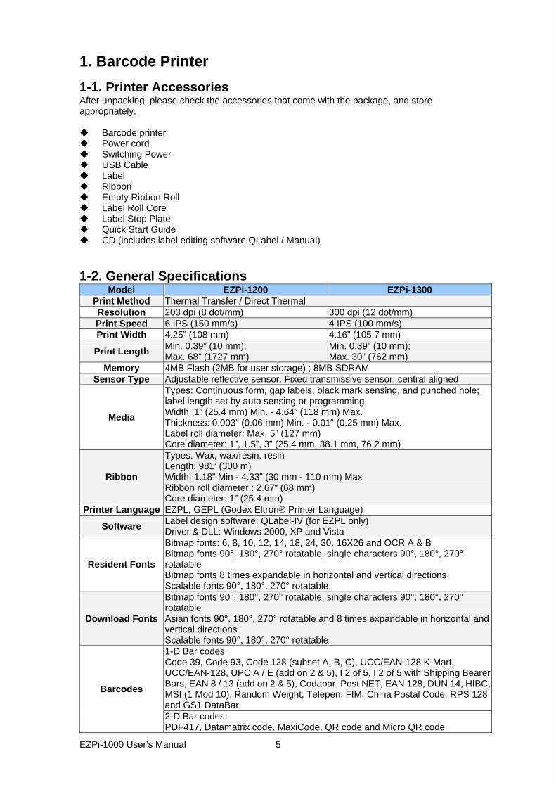
1. Barcode Printer 1-1. Printer Accessories After unpacking, please check the accessories that come with the package, and store appropriately.
Barcode printer Power cord Switching Power USB Cable Label Ribbon Empty Ribbon Roll Label Roll Core Label Stop Plate Quick Start Guide CD (includes label editing software QLabel / Manual)
1-2. General Specifications
Model EZPi-1200 EZPi-1300Print Method Thermal Transfer / Direct Thermal Resolution 203 dpi (8 dot/mm) 300 dpi (12 dot/mm) Print Speed 6 IPS (150 mm/s) 4 IPS (100 mm/s) Print Width 4.25” (108 mm) 4.16” (105.7 mm)
Print Length Min. 0.39” (10 mm); Max. 68” (1727 mm)
Min. 0.39” (10 mm); Max. 30” (762 mm)
Memory 4MB Flash (2MB for user storage) ; 8MB SDRAM Sensor Type Adjustable reflective sensor. Fixed transmissive sensor, central aligned
Media
Types: Continuous form, gap labels, black mark sensing, and punched hole; label length set by auto sensing or programming Width: 1” (25.4 mm) Min. - 4.64” (118 mm) Max. Thickness: 0.003” (0.06 mm) Min. - 0.01” (0.25 mm) Max. Label roll diameter: Max. 5” (127 mm) Core diameter: 1”, 1.5”, 3” (25.4 mm, 38.1 mm, 76.2 mm)
Ribbon
Types: Wax, wax/resin, resin Length: 981’ (300 m) Width: 1.18” Min - 4.33” (30 mm - 110 mm) Max Ribbon roll diameter.: 2.67“ (68 mm) Core diameter: 1” (25.4 mm)
Printer Language EZPL, GEPL (Godex Eltron® Printer Language)
Software Label design software: QLabel-IV (for EZPL only) Driver & DLL: Windows 2000, XP and Vista
Resident Fonts
Bitmap fonts: 6, 8, 10, 12, 14, 18, 24, 30, 16X26 and OCR A & B Bitmap fonts 90°, 180°, 270° rotatable, single characters 90°, 180°, 270° rotatable Bitmap fonts 8 times expandable in horizontal and vertical directions Scalable fonts 90°, 180°, 270° rotatable
Download Fonts
Bitmap fonts 90°, 180°, 270° rotatable, single characters 90°, 180°, 270° rotatable Asian fonts 90°, 180°, 270° rotatable and 8 times expandable in horizontal and vertical directions Scalable fonts 90°, 180°, 270° rotatable 1-D Bar codes: Code 39, Code 93, Code 128 (subset A, B, C), UCC/EAN-128 K-Mart, UCC/EAN-128, UPC A / E (add on 2 & 5), I 2 of 5, I 2 of 5 with Shipping Bearer Bars, EAN 8 / 13 (add on 2 & 5), Codabar, Post NET, EAN 128, DUN 14, HIBC, MSI (1 Mod 10), Random Weight, Telepen, FIM, China Postal Code, RPS 128 and GS1 DataBar
Barcodes
2-D Bar codes: PDF417, Datamatrix code, MaxiCode, QR code and Micro QR code
EZPi-1000 User’s Manual
5
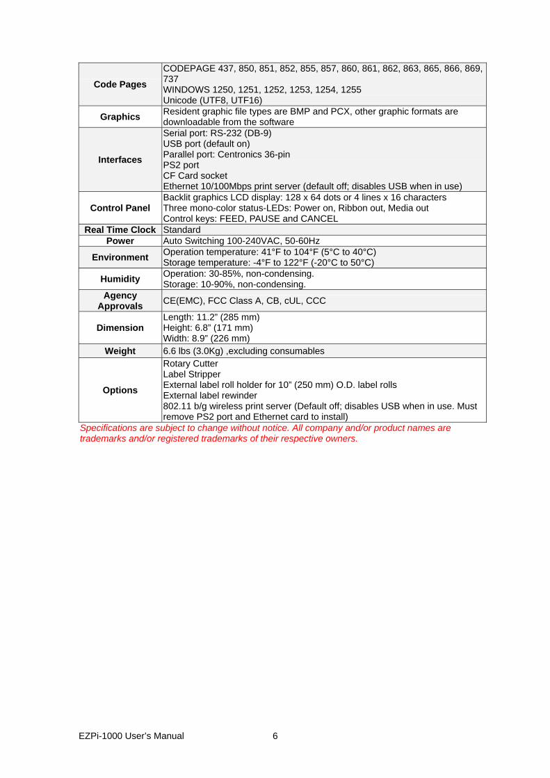
Code Pages CODEPAGE 437, 850, 851, 852, 855, 857, 860, 861, 862, 863, 865, 866, 869, 737 WINDOWS 1250, 1251, 1252, 1253, 1254, 1255 Unicode (UTF8, UTF16)
Graphics Resident graphic file types are BMP and PCX, other graphic formats are downloadable from the software
Interfaces
Serial port: RS-232 (DB-9) USB port (default on) Parallel port: Centronics 36-pin PS2 port CF Card socket Ethernet 10/100Mbps print server (default off; disables USB when in use)
Control Panel Backlit graphics LCD display: 128 x 64 dots or 4 lines x 16 characters Three mono-color status-LEDs: Power on, Ribbon out, Media out Control keys: FEED, PAUSE and CANCEL
Real Time Clock Standard Power Auto Switching 100-240VAC, 50-60Hz
Environment Operation temperature: 41°F to 104°F (5°C to 40°C) Storage temperature: -4°F to 122°F (-20°C to 50°C)
Humidity Operation: 30-85%, non-condensing. Storage: 10-90%, non-condensing.
Agency Approvals CE(EMC), FCC Class A, CB, cUL, CCC
Dimension Length: 11.2” (285 mm) Height: 6.8” (171 mm) Width: 8.9” (226 mm)
Weight 6.6 lbs (3.0Kg) ,excluding consumables
Options
Rotary Cutter Label Stripper External label roll holder for 10” (250 mm) O.D. label rolls External label rewinder 802.11 b/g wireless print server (Default off; disables USB when in use. Must remove PS2 port and Ethernet card to install)
Specifications are subject to change without notice. All company and/or product names are trademarks and/or registered trademarks of their respective owners.
EZPi-1000 User’s Manual
6
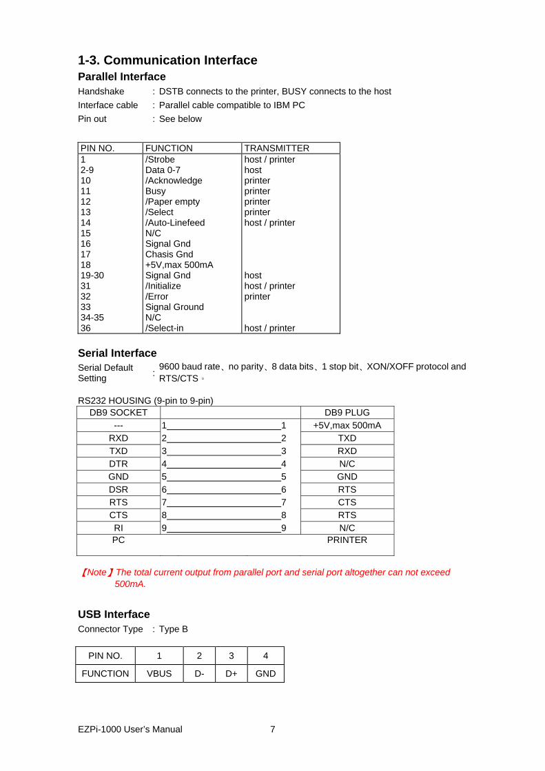
1-3. Communication Interface Parallel Interface Handshake : DSTB connects to the printer, BUSY connects to the host Interface cable : Parallel cable compatible to IBM PC Pin out : See below
PIN NO. FUNCTION TRANSMITTER 1 2-9 10 11 12 13 14 15 16 17 18 19-30 31 32 33 34-35 36
/Strobe Data 0-7 /Acknowledge Busy /Paper empty /Select /Auto-Linefeed N/C Signal Gnd Chasis Gnd +5V,max 500mA Signal Gnd /Initialize /Error Signal Ground N/C /Select-in
host / printer host printer printer printer printer host / printer host host / printer printer host / printer
Serial Interface Serial Default Setting :
9600 baud rate、no parity、8 data bits、1 stop bit、XON/XOFF protocol and RTS/CTS。
RS232 HOUSING (9-pin to 9-pin)
DB9 SOCKET DB9 PLUG --- 1 1 +5V,max 500mA
RXD 2 2 TXD TXD 3 3 RXD DTR 4 4 N/C GND 5 5 GND DSR 6 6 RTS RTS 7 7 CTS CTS 8 8 RTS RI 9 9 N/C PC PRINTER
【Note】The total current output from parallel port and serial port altogether can not exceed
500mA. USB Interface Connector Type : Type B
PIN NO. 1 2 3 4
FUNCTION VBUS D- D+ GND
EZPi-1000 User’s Manual
7
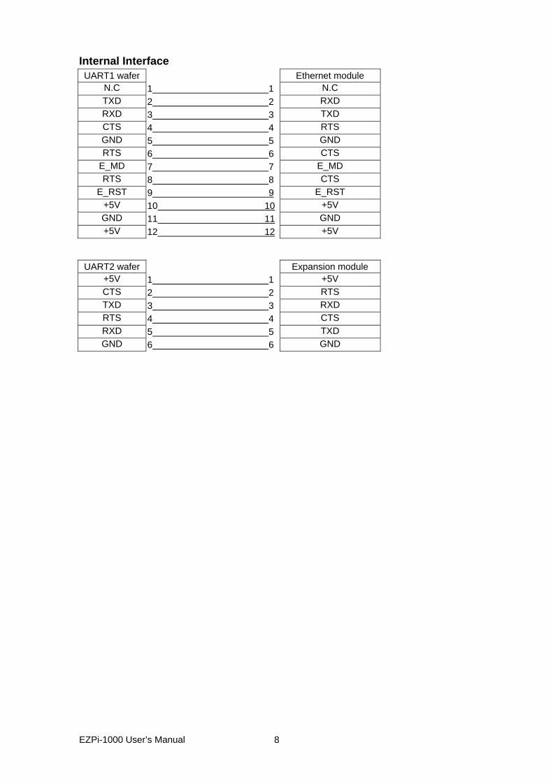
Internal Interface UART1 wafer Ethernet module
N.C 1 1 N.C TXD 2 2 RXD RXD 3 3 TXD CTS 4 4 RTS GND 5 5 GND RTS 6 6 CTS
E_MD 7 7 E_MD RTS 8 8 CTS
E_RST 9 9 E_RST +5V 10 10 +5V GND 11 11 GND +5V 12 12 +5V
UART2 wafer Expansion module
+5V 1 1 +5V CTS 2 2 RTS TXD 3 3 RXD RTS 4 4 CTS RXD 5 5 TXD GND 6 6 GND
EZPi-1000 User’s Manual
8
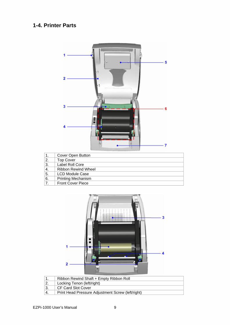
1-4. Printer Parts
1. Cover Open Button 2. Top Cover 3. Label Roll Core 4. Ribbon Rewind Wheel 5. LCD Module Case 6. Printing Mechanism 7. Front Cover Piece
1. Ribbon Rewind Shaft + Empty Ribbon Roll 2. Locking Tenon (left/right) 3. CF Card Slot Cover 4. Print Head Pressure Adjustment Screw (left/right)
EZPi-1000 User’s Manual
9
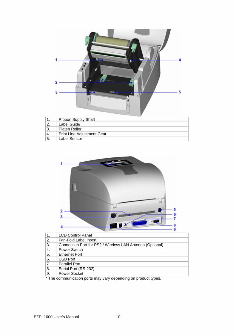
1. Ribbon Supply Shaft 2. Label Guide 3. Platen Roller 4. Print Line Adjustment Gear 5. Label Sensor
1. LCD Control Panel 2. Fan-Fold Label Insert 3. Connection Port for PS2 / Wireless LAN Antenna (Optional) 4. Power Switch 5. Ethernet Port 6. USB Port 7. Parallel Port 8. Serial Port (RS-232) 9. Power Socket * The communication ports may vary depending on product types.
EZPi-1000 User’s Manual
10
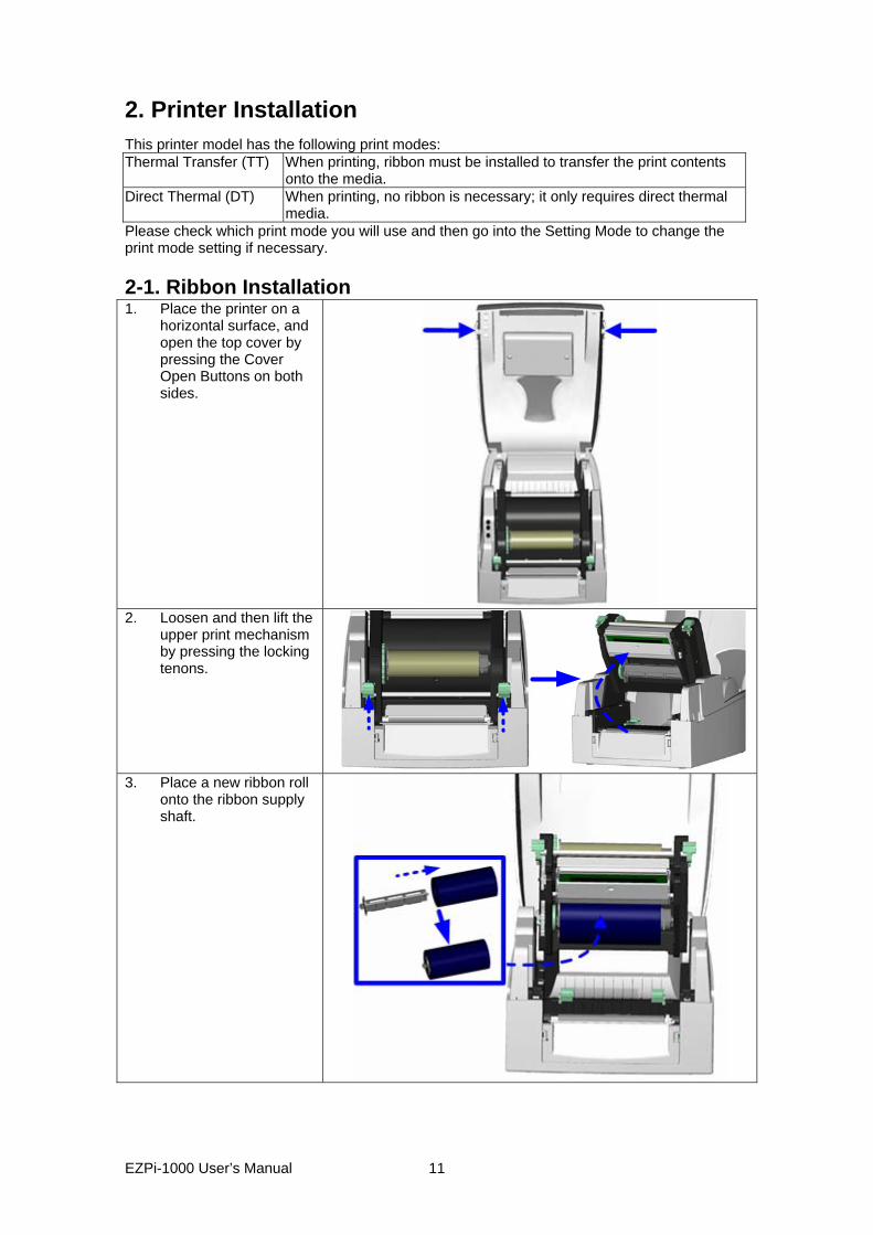
2. Printer Installation This printer model has the following print modes: Thermal Transfer (TT) When printing, ribbon must be installed to transfer the print contents
onto the media. Direct Thermal (DT) When printing, no ribbon is necessary; it only requires direct thermal
media. Please check which print mode you will use and then go into the Setting Mode to change the print mode setting if necessary. 2-1. Ribbon Installation 1. Place the printer on a
horizontal surface, and open the top cover by pressing the Cover Open Buttons on both sides.
2. Loosen and then lift the
upper print mechanism by pressing the locking tenons.
3. Place a new ribbon roll onto the ribbon supply shaft.
EZPi-1000 User’s Manual
11
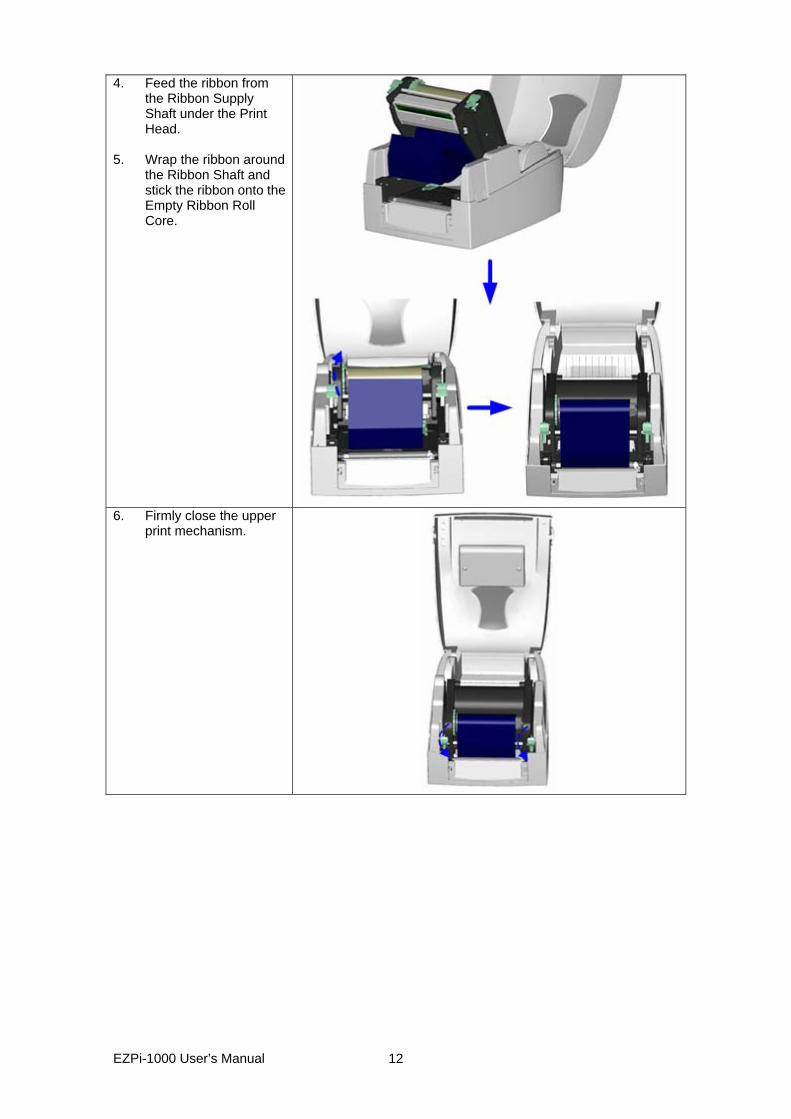
4. Feed the ribbon from the Ribbon Supply Shaft under the Print Head.
5. Wrap the ribbon around
the Ribbon Shaft and stick the ribbon onto the Empty Ribbon Roll Core.
6. Firmly close the upper print mechanism.
EZPi-1000 User’s Manual
12
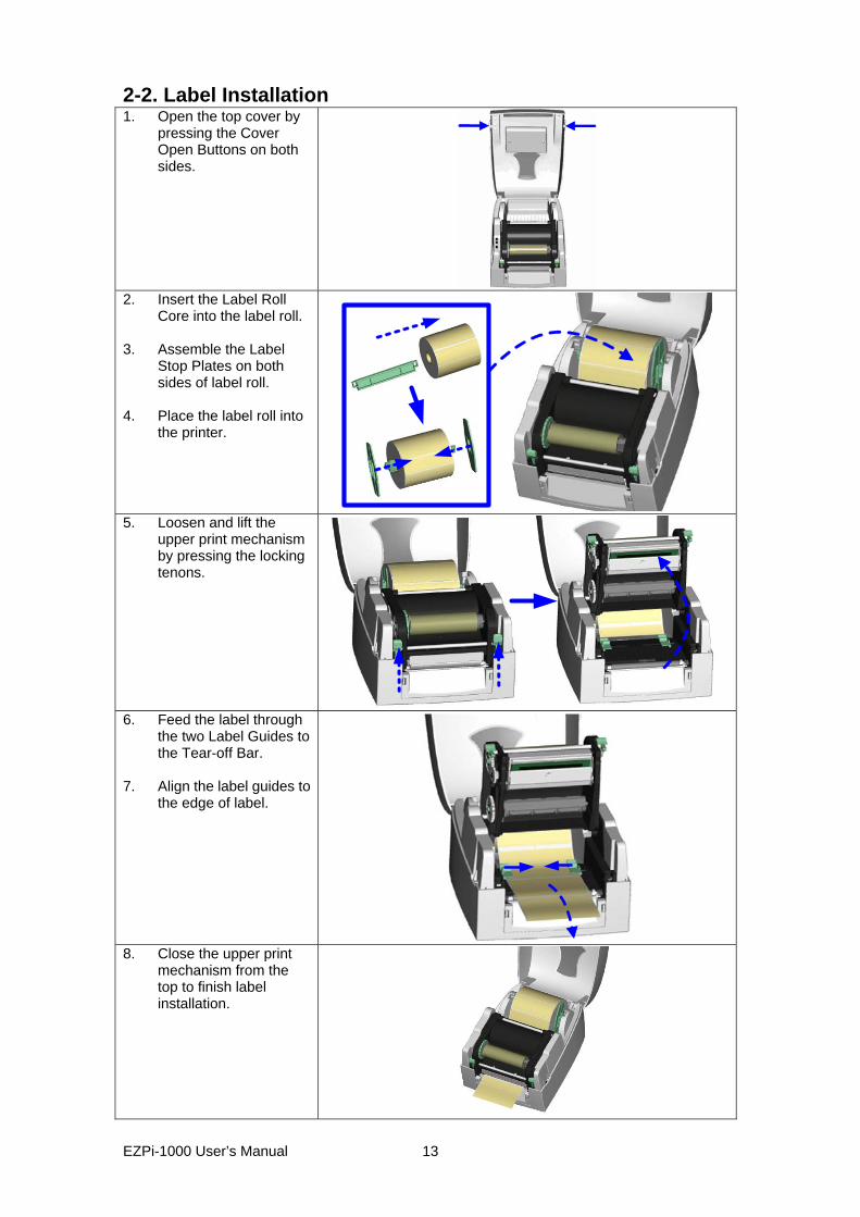
2-2. Label Installation 1. Open the top cover by
pressing the Cover Open Buttons on both sides.
2. Insert the Label Roll
Core into the label roll. 3. Assemble the Label
Stop Plates on both sides of label roll.
4. Place the label roll into
the printer.
5. Loosen and lift the
upper print mechanism by pressing the locking tenons.
6. Feed the label through the two Label Guides to the Tear-off Bar.
7. Align the label guides to
the edge of label.
8. Close the upper print
mechanism from the top to finish label installation.
EZPi-1000 User’s Manual
13
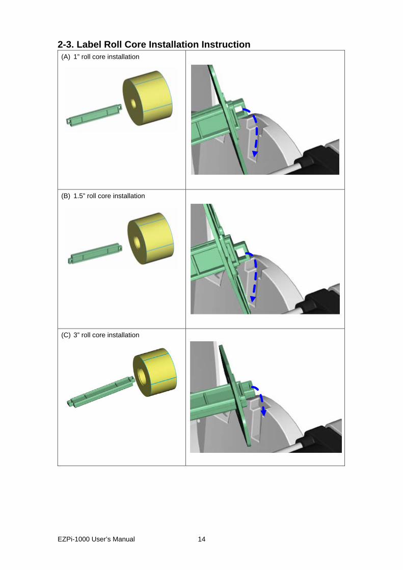
2-3. Label Roll Core Installation Instruction (A) 1” roll core installation
(B) 1.5” roll core installation
(C) 3” roll core installation
EZPi-1000 User’s Manual
14
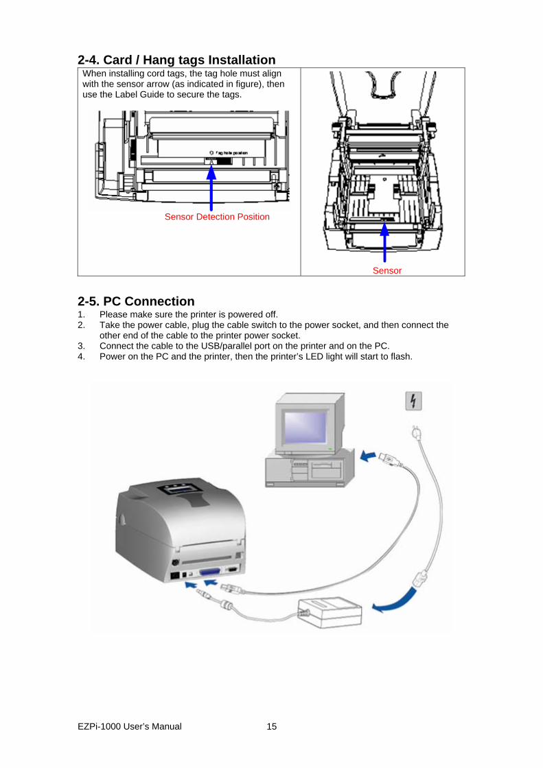
2-4. Card / Hang tags Installation When installing cord tags, the tag hole must align with the sensor arrow (as indicated in figure), then use the Label Guide to secure the tags.
Sensor Detection Position
Sensor
2-5. PC Connection 1. Please make sure the printer is powered off. 2. Take the power cable, plug the cable switch to the power socket, and then connect the
other end of the cable to the printer power socket. 3. Connect the cable to the USB/parallel port on the printer and on the PC. 4. Power on the PC and the printer, then the printer’s LED light will start to flash.
EZPi-1000 User’s Manual
15
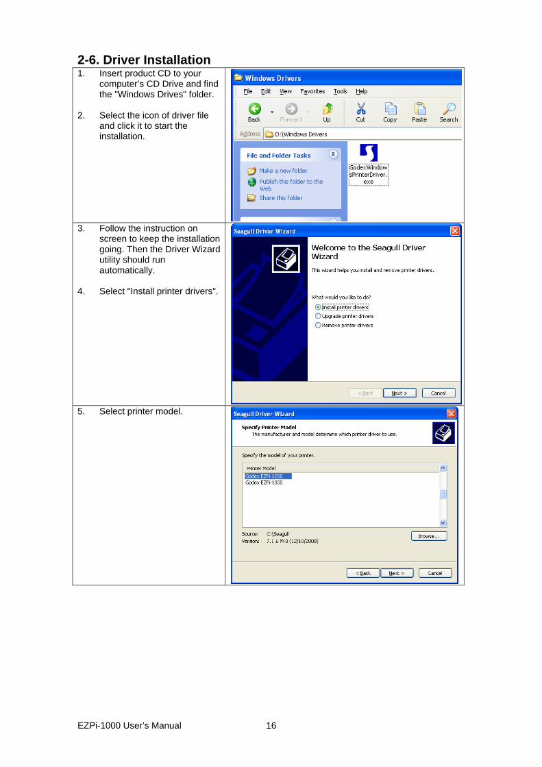
2-6. Driver Installation 1. Insert product CD to your
computer’s CD Drive and find the "Windows Drives" folder.
2. Select the icon of driver file
and click it to start the installation.
3. Follow the instruction on screen to keep the installation going. Then the Driver Wizard utility should run automatically.
4. Select "Install printer drivers".
5. Select printer model.
EZPi-1000 User’s Manual
16
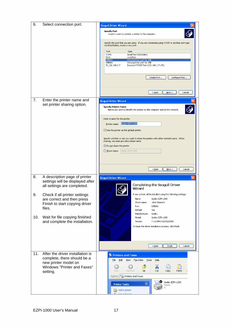
6. Select connection port.
7. Enter the printer name and set printer sharing option.
8. A description page of printer settings will be displayed after all settings are completed.
9. Check if all printer settings
are correct and then press Finish to start copying driver files.
10. Wait for file copying finished
and complete the installation.
11. After the driver installation is complete, there should be a new printer model on Windows "Printer and Faxes" setting.
EZPi-1000 User’s Manual
17
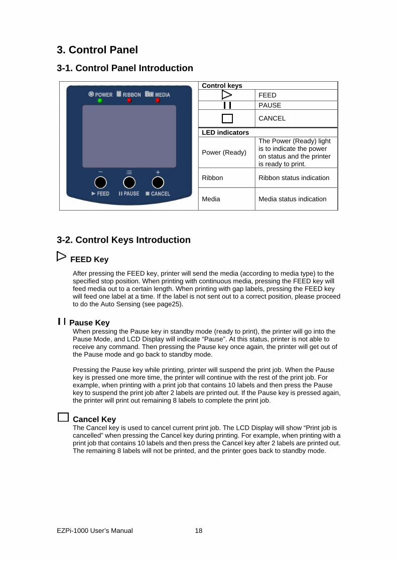
3. Control Panel 3-1. Control Panel Introduction
Control keys
FEED
PAUSE
CANCEL
LED indicators
Power (Ready)
The Power (Ready) light is to indicate the power on status and the printer is ready to print.
Ribbon Ribbon status indication
Media Media status indication
3-2. Control Keys Introduction
FEED Key After pressing the FEED key, printer will send the media (according to media type) to the specified stop position. When printing with continuous media, pressing the FEED key will feed media out to a certain length. When printing with gap labels, pressing the FEED key will feed one label at a time. If the label is not sent out to a correct position, please proceed to do the Auto Sensing (see page25).
Pause Key When pressing the Pause key in standby mode (ready to print), the printer will go into the Pause Mode, and LCD Display will indicate “Pause”. At this status, printer is not able to receive any command. Then pressing the Pause key once again, the printer will get out of the Pause mode and go back to standby mode.
Pressing the Pause key while printing, printer will suspend the print job. When the Pause key is pressed one more time, the printer will continue with the rest of the print job. For example, when printing with a print job that contains 10 labels and then press the Pause key to suspend the print job after 2 labels are printed out. If the Pause key is pressed again, the printer will print out remaining 8 labels to complete the print job.
Cancel Key The Cancel key is used to cancel current print job. The LCD Display will show “Print job is cancelled” when pressing the Cancel key during printing. For example, when printing with a print job that contains 10 labels and then press the Cancel key after 2 labels are printed out. The remaining 8 labels will not be printed, and the printer goes back to standby mode.
EZPi-1000 User’s Manual
18
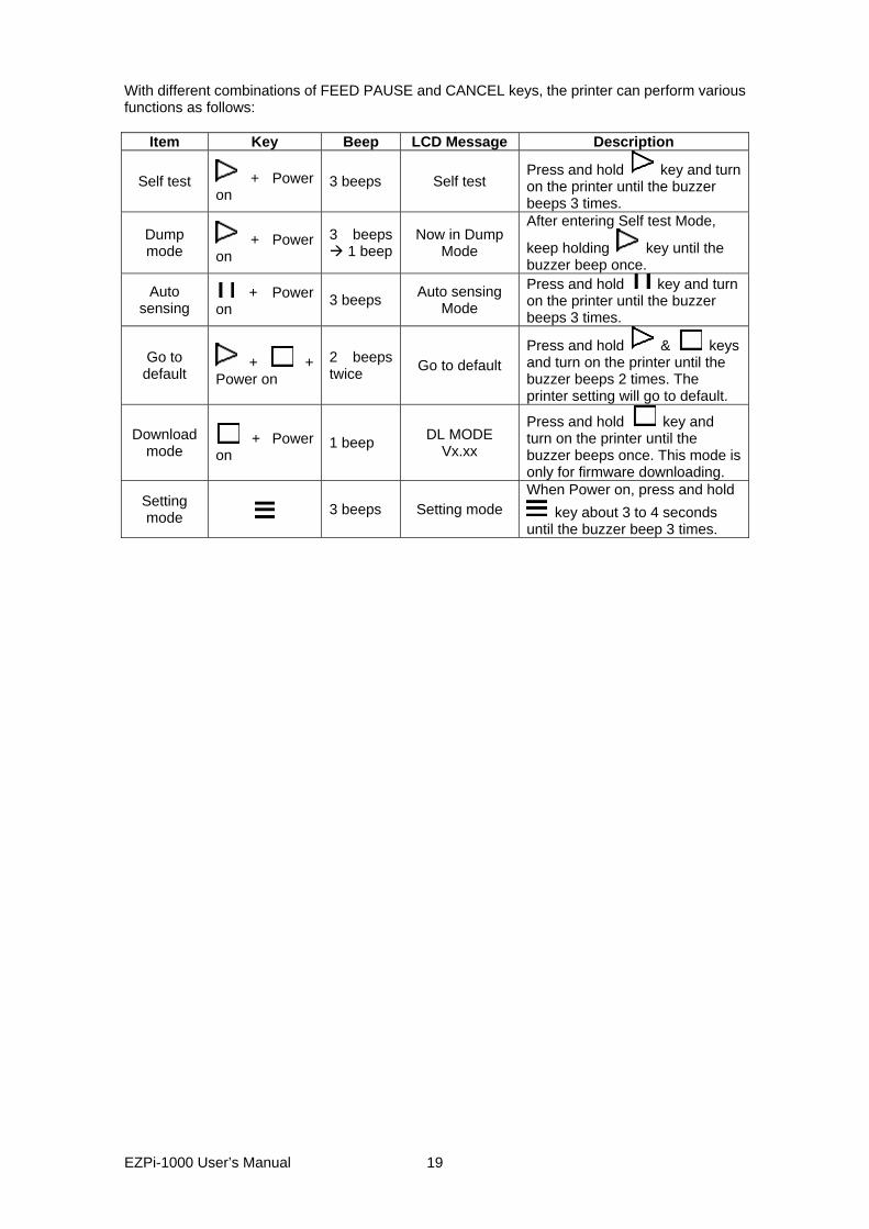
With different combinations of FEED PAUSE and CANCEL keys, the printer can perform various functions as follows:
Item Key Beep LCD Message Description
Self test + Power on
3 beeps Self test Press and hold key and turn on the printer until the buzzer beeps 3 times.
Dump mode
+ Power on
3 beeps 1 beep
Now in Dump Mode
After entering Self test Mode,
keep holding key until the buzzer beep once.
Auto sensing
+ Power on 3 beeps Auto sensing
Mode Press and hold key and turn on the printer until the buzzer beeps 3 times.
Go to default
+ + Power on
2 beeps twice Go to default
Press and hold & keys and turn on the printer until the buzzer beeps 2 times. The printer setting will go to default.
Download mode
+ Power on
1 beep DL MODE Vx.xx
Press and hold key and turn on the printer until the buzzer beeps once. This mode is only for firmware downloading.
Setting mode 3 beeps Setting mode
When Power on, press and hold key about 3 to 4 seconds
until the buzzer beep 3 times.
EZPi-1000 User’s Manual
19
3-3. Setting mode In the Setting Mode, changes can be made according to requirement on the printing mode, options, media type, and parallel interface (printer can only go into setting when connected to PC by parallel cable, USB cable, or serial cable). 1. Power on the printer and make sure it is on “Ready to print” status. 2. Press and hold Pause key about 3 to 4 seconds until the buzzer beep 3 times, and then the
LCD will display “Setting Mode”. 3. In the Setting Mode, the keys have the following functions:
: MINUS / Enter : MENU / NEXT : PLUS / Exit 4. Before exiting the Setting mode, the LCD will prompt to ask whether save the settings or
not. After user’s response on whether do or do not save the settings, printer will exit from Setting mode and return to standby mode.
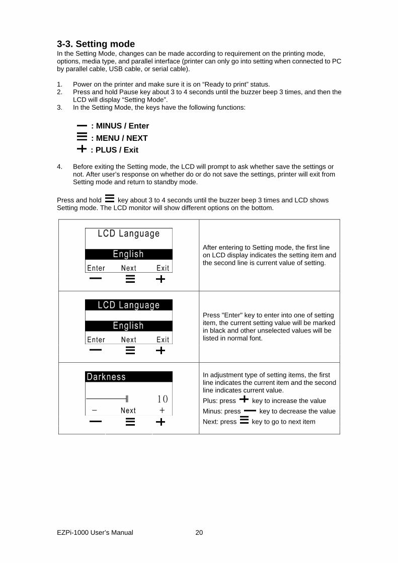
Press and hold key about 3 to 4 seconds until the buzzer beep 3 times and LCD shows Setting mode. The LCD monitor will show different options on the bottom.
After entering to Setting mode, the first line on LCD display indicates the setting item and the second line is current value of setting.
Press "Enter" key to enter into one of setting item, the current setting value will be marked in black and other unselected values will be listed in normal font.
In adjustment type of setting items, the first line indicates the current item and the second line indicates current value. Plus: press key to increase the value Minus: press key to decrease the valueNext: press key to go to next item
EZPi-1000 User’s Manual
20
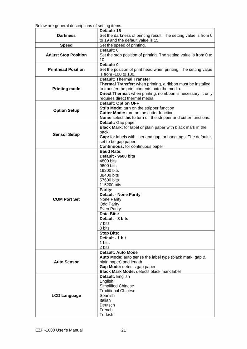
Below are general descriptions of setting items.
Darkness Default: 15Set the darkness of printing result. The setting value is from 0 to 19 and the default value is 15.
Speed Set the speed of printing.
Adjust Stop Position Default: 0Set the stop position of printing. The setting value is from 0 to 10.
Printhead Position Default: 0Set the position of print head when printing. The setting value is from -100 to 100.
Printing mode
Default: Thermal Transfer Thermal Transfer: when printing, a ribbon must be installed to transfer the print contents onto the media. Direct Thermal: when printing, no ribbon is necessary; it only requires direct thermal media.
Option Setup Default: Option OFF Strip Mode: turn on the stripper function Cutter Mode: turn on the cutter function None: select this to turn off the stripper and cutter functions.
Sensor Setup
Default: Gap paper Black Mark: for label or plain paper with black mark in the back Gap: for labels with liner and gap, or hang tags. The default is set to be gap paper. Continuous: for continuous paper Baud Rate: Default - 9600 bits 4800 bits 9600 bits 19200 bits 38400 bits 57600 bits 115200 bits Parity: Default - None Parity None Parity Odd Parity Even Parity Data Bits: Default - 8 bits 7 bits 8 bits
COM Port Set
Stop Bits: Default - 1 bit 1 bits 2 bits
Auto Sensor
Default: Auto Mode Auto Mode: auto sense the label type (black mark, gap & plain paper) and length Gap Mode: detects gap paper Black Mark Mode: detects black mark label
LCD Language
Default: English English Simplified Chinese Traditional Chinese Spanish Italian Deutsch French Turkish
EZPi-1000 User’s Manual
21
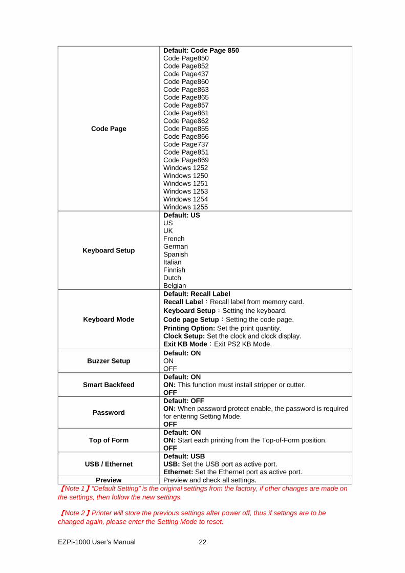
Code Page
Default: Code Page 850 Code Page850 Code Page852 Code Page437 Code Page860 Code Page863 Code Page865 Code Page857 Code Page861 Code Page862 Code Page855 Code Page866 Code Page737 Code Page851 Code Page869 Windows 1252 Windows 1250 Windows 1251 Windows 1253 Windows 1254 Windows 1255
Keyboard Setup
Default: US US UK French German Spanish Italian Finnish Dutch Belgian
Keyboard Mode
Default: Recall Label Recall Label:Recall label from memory card. Keyboard Setup:Setting the keyboard. Code page Setup:Setting the code page. Printing Option: Set the print quantity. Clock Setup: Set the clock and clock display. Exit KB Mode:Exit PS2 KB Mode.
Buzzer Setup Default: ON ON OFF
Smart Backfeed Default: ON ON: This function must install stripper or cutter. OFF
Password Default: OFF ON: When password protect enable, the password is required for entering Setting Mode. OFF
Top of Form Default: ON ON: Start each printing from the Top-of-Form position. OFF
USB / Ethernet Default: USB USB: Set the USB port as active port. Ethernet: Set the Ethernet port as active port.
Preview Preview and check all settings. 【Note 1】“Default Setting” is the original settings from the factory, if other changes are made on the settings, then follow the new settings. 【Note 2】Printer will store the previous settings after power off, thus if settings are to be changed again, please enter the Setting Mode to reset.
EZPi-1000 User’s Manual
22
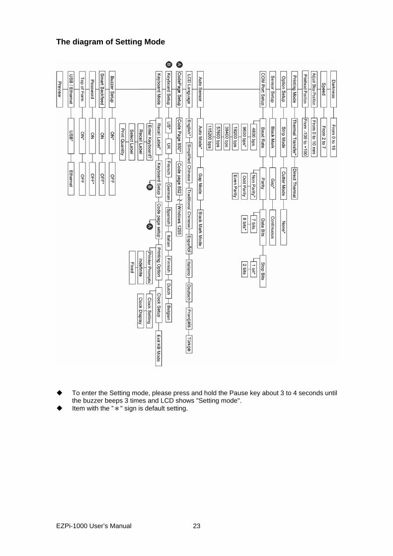
The diagram of Setting Mode
To enter the Setting mode, please press and hold the Pause key about 3 to 4 seconds until
the buzzer beeps 3 times and LCD shows "Setting mode". Item with the ”*" sign is default setting.
EZPi-1000 User’s Manual
23
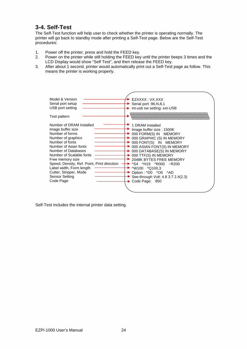
3-4. Self-Test The Self-Test function will help user to check whether the printer is operating normally. The printer will go back to standby mode after printing a Self-Test page. Below are the Self-Test procedures: 1. Power off the printer, press and hold the FEED key. 2. Power on the printer while still holding the FEED key until the printer beeps 3 times and the
LCD Display would show “Self Test”, and then release the FEED key. 3. After about 1 second, printer would automatically print out a Self-Test page as follow. This
means the printer is working properly.
EZXXXX : VX.XXX Serial port :96,N,8,1 int-usb sw setting: ext-USB 1 DRAM installed Image buffer size : 1500K 000 FORM(S) IN MEMORY 000 GRAPHIC (S) IN MEMORY 000 FONT(S) IN MEMORY 000 ASIAN FONT(S) IN MEMORY 000 DATABASE(S) IN MEMORY 000 TTF(S) IN MEMORY 2048K BYTES FREE MEMORY ^S4 ^H19 ^R000 ~R200 ^W100 ^Q100,3 Option : ^D0 ^O0 ^AD See-through Volt: 4.8 3.7 2.4(2.3) Code Page: 850
Model & Version Serial port setup USB port setting Test pattern Number of DRAM installed Image buffer size Number of forms Number of graphics Number of fonts Number of Asian fonts Number of Databases Number of Scalable fonts Free memory size Speed, Density, Ref. Point, Print directionLabel width, Form length Cutter, Stripper, Mode Sensor Setting Code Page
Self-Test includes the internal printer data setting.
EZPi-1000 User’s Manual
24
3-5. Dump Mode When the print result doesn’t match the label setting, it’s recommended to go into the Dump Mode to check whether there is a mistake in data transmission between the printer and the PC. For example, when printer receives 8 commands, yet without processing these commands, only printed out the contents of the commands, this will confirm whether the commands were received correctly. Test procedures to enter the Dump Mode are as follows: 1. Power off the printer, press and hold the FEED key. 2. Power on the printer (while still holding the FEED key). 3. When LCD Display shows “DUMP MODE BEGIN,” then release the FEED key. Printer will
automatically print “DUMP MODE BEGIN.” This means the printer is already in Dump Mode.
4. Send commands to the printer, and check if printed content matches the commands that just be sent.
To cancel (get out of) the Dump Mode, please press the FEED key, and then the printer will automatically print “OUT OF DUMP MODE.” This indicates that the printer is back to the standby mode. 3-6. Auto Sensing Printer can automatically detect the paper length and record it. By this way, users do not need to set the paper length and the printer can accurately detect the position of paper gap. 1. Check if the paper is loaded properly. 2. Power off the printer, press and hold the Pause key. 3. Power on the printer while still holding the Pause key until the printer beeps 3 times and the
LCD Display shows “Auto Sensing mode,” then release the Pause key. The printer will automatically detect the label size/length and record the information.
4. LCD Display shows the results of measurement. The printer will be back to standby mode after displaying the result of Auto Sensing.
EZPi-1000 User’s Manual
25

3-7. Keyboard Mode EZPi-1000 series printer can support keyboard with PS2 interface. To connect the PS2 keyboard, please do as follows:
1. Please be sure the printer power is on and is showing no error message. 2. Power off the printer and then plug the PS2 keyboard connector into the socket in the back
of printer. 3. Power on the printer, the message “Enter keyboard Mode [y/n]” will be displayed on the
LCD. Press FEED key on LCD control panel or press “Y” on PS2 keyboard to enter the Keyboard Mode.
While in the keyboard mode, you may press "Esc" key (or press CANCEL key on LCD panel) anytime to go back to the previous page, and at the end you will be prompted to exit the keyboard mode. When “Exit Keyboard Mode [y/n]” message is displayed on the LCD, enter “y” (or press FEED key on LCD panel) to leave the PS2 keyboard mode. To re-enter the keyboard mode, just restart the printer or select the "Keyboard mode" function in setting mode. To change the keyboard setting, please refer to the "Setting Mode diagram" in Chapter 3.3 . Print a label with stored form in Keyboard Mode
^FTEST1 ^Q100,3 ^W100 ^H10 ^P1 ^S2 ^AD ^C1 ^R0 ~Q+0 ^O0 ^D0 ^E12 ~R200 ^L Dy2-me-dd Th:m:s C0,00001,+1,Serial Number V00,16,Product Name,jc0 V01,16,Price,jc0 AF,330,566,1,1,0,0,^C0 AH,212,168,1,1,0,0,^V00 AG,308,396,1,1,0,0,^V01 E
1. At least one label form has to be stored in printer before you can print with keyboard mode. To create a sample label form as above figure shows, please copy printing commands that listed on left column and send it to printer via QLabel or Hyper Terminal.
2. The sample label form includes 2 variables and 1 serial number: "Product name", "Price" and "Serial Number". The printing will not start until the values of 3 variables are provided.
3. Power off the printer, plug the connector of PS2 keyboard, and then power on the printer again.
4. Press “y “ to enter Keyboard mode
5. Press Enter to confirm the file selection * Note: press either ↑ or ↓ can select previous or next label format
EZPi-1000 User’s Manual
26

6. LCD will show the Serial Number Prompt.
7. Key in the start value. (Example:00001)
8. LCD will show the first Variable Prompt.
9. Key in the variable data. (Example: Apple)
10. LCD will show the second Variable Prompt.
11. Key in the variable data. (Example: 199)
12. LCD shows the Print quantity. 13. Key in the print quantity. (Example: 3)
EZPi-1000 User’s Manual
27
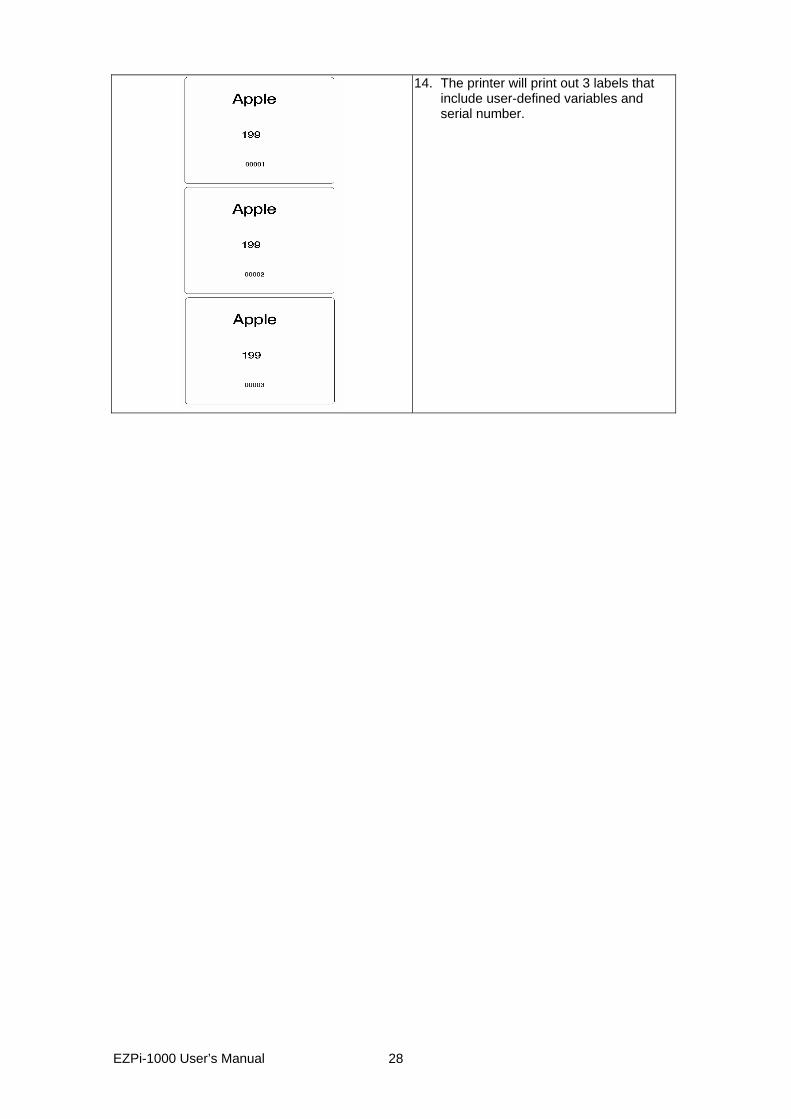
14. The printer will print out 3 labels that include user-defined variables and serial number.
EZPi-1000 User’s Manual
28
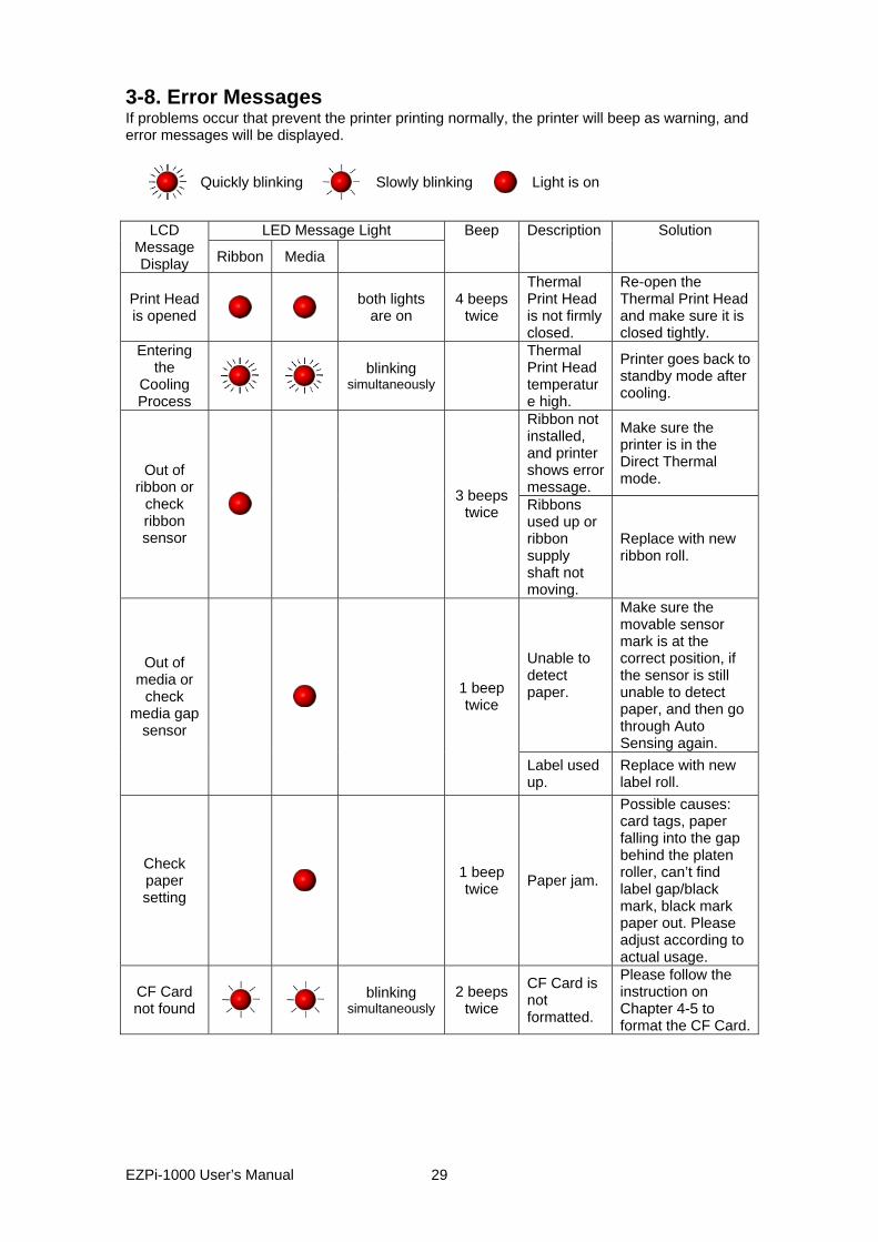
3-8. Error Messages If problems occur that prevent the printer printing normally, the printer will beep as warning, and error messages will be displayed.
Quickly blinking
Slowly blinking Light is on
LED Message Light LCD
Message Display Ribbon Media
Beep Description Solution
Print Head is opened
both lights are on
4 beeps twice
Thermal Print Head is not firmly closed.
Re-open the Thermal Print Head and make sure it is closed tightly.
Entering the
Cooling Process
blinking
simultaneously
Thermal Print Head temperature high.
Printer goes back to standby mode after cooling.
Ribbon not installed, and printer shows error message.
Make sure the printer is in the Direct Thermal mode. Out of
ribbon or check ribbon sensor
3 beeps twice Ribbons
used up or ribbon supply shaft not moving.
Replace with new ribbon roll.
Unable to detect paper.
Make sure the movable sensor mark is at the correct position, if the sensor is still unable to detect paper, and then go through Auto Sensing again.
Out of media or
check media gap
sensor
1 beep twice
Label used up.
Replace with new label roll.
Check paper setting
1 beep twice Paper jam.
Possible causes: card tags, paper falling into the gap behind the platen roller, can’t find label gap/black mark, black mark paper out. Please adjust according to actual usage.
CF Card not found
blinking simultaneously
2 beeps twice
CF Card is not formatted.
Please follow the instruction on Chapter 4-5 to format the CF Card.
EZPi-1000 User’s Manual
29

Memory Full
2 beeps twice
Memory is full
Delete unnecessary data in the memory or use CF Card.
Filename can not be
found 2 beeps
twice Can’t find the file
Use “~X4” command to print out all the files, then check whether the file exist and the names are correct.
Filename repeated
2 beeps
twice File name is repeated
Change the file name and download again.
EZPi-1000 User’s Manual
30
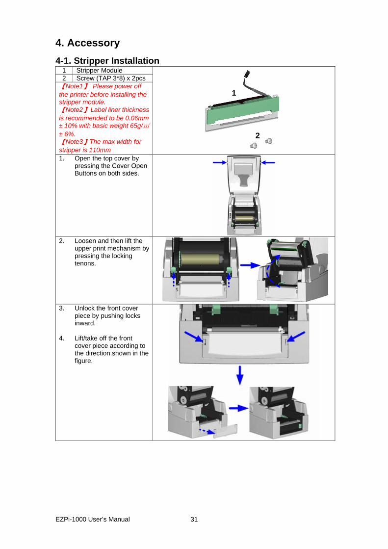
4. Accessory 4-1. Stripper Installation
1 Stripper Module 2 Screw (TAP 3*8) x 2pcs
【Note1】 Please power off the printer before installing the stripper module. 【Note2】 Label liner thickness is recommended to be 0.06mm ± 10% with basic weight 65g/㎡± 6%. 【Note3】The max width for stripper is 110mm
2
1
1. Open the top cover by
pressing the Cover Open Buttons on both sides.
2. Loosen and then lift the
upper print mechanism by pressing the locking tenons.
3. Unlock the front cover
piece by pushing locks inward.
4. Lift/take off the front
cover piece according to the direction shown in the figure.
EZPi-1000 User’s Manual
31
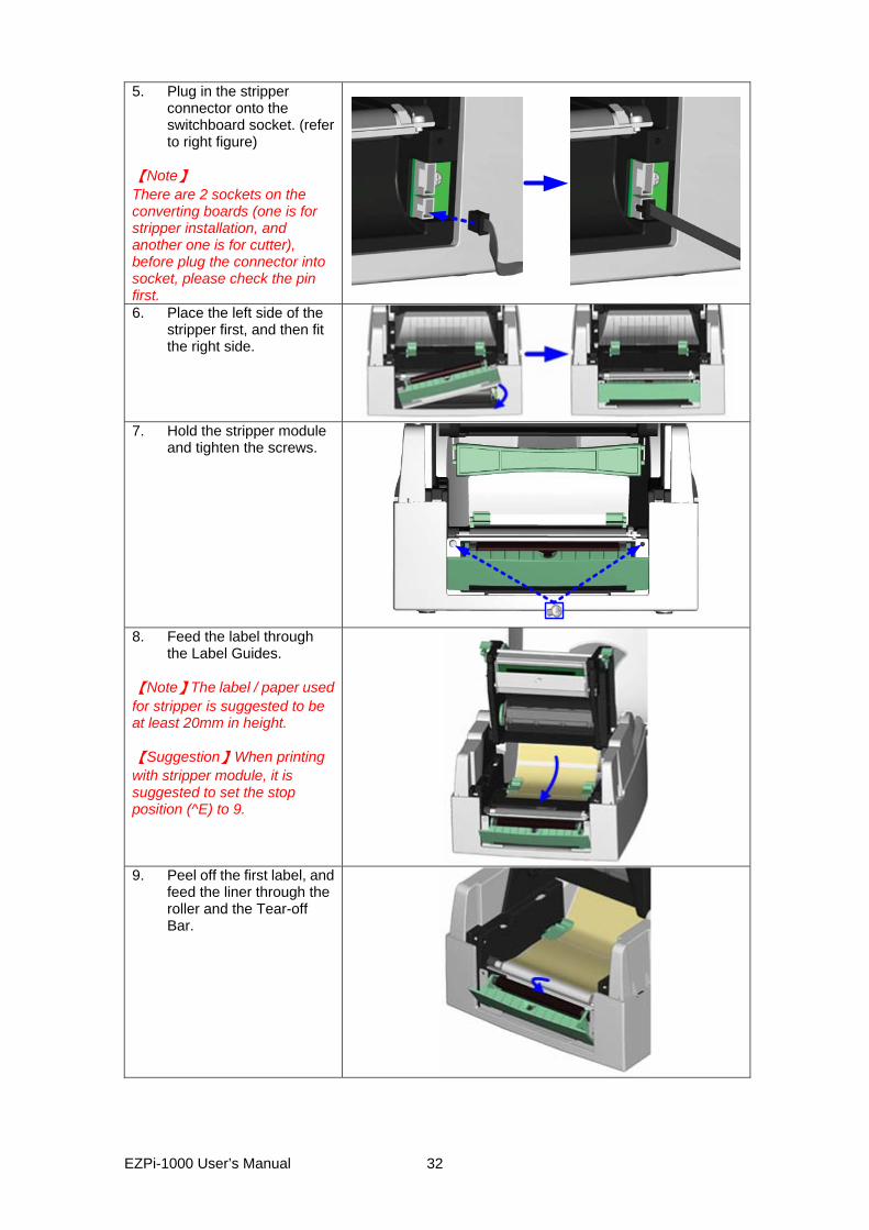
5. Plug in the stripper connector onto the switchboard socket. (refer to right figure)
【Note】 There are 2 sockets on the converting boards (one is for stripper installation, and another one is for cutter), before plug the connector into socket, please check the pin first. 6. Place the left side of the
stripper first, and then fit the right side.
7. Hold the stripper module
and tighten the screws.
8. Feed the label through
the Label Guides. 【Note】The label / paper used for stripper is suggested to be at least 20mm in height. 【Suggestion】When printing with stripper module, it is suggested to set the stop position (^E) to 9.
9. Peel off the first label, and
feed the liner through the roller and the Tear-off Bar.
EZPi-1000 User’s Manual
32
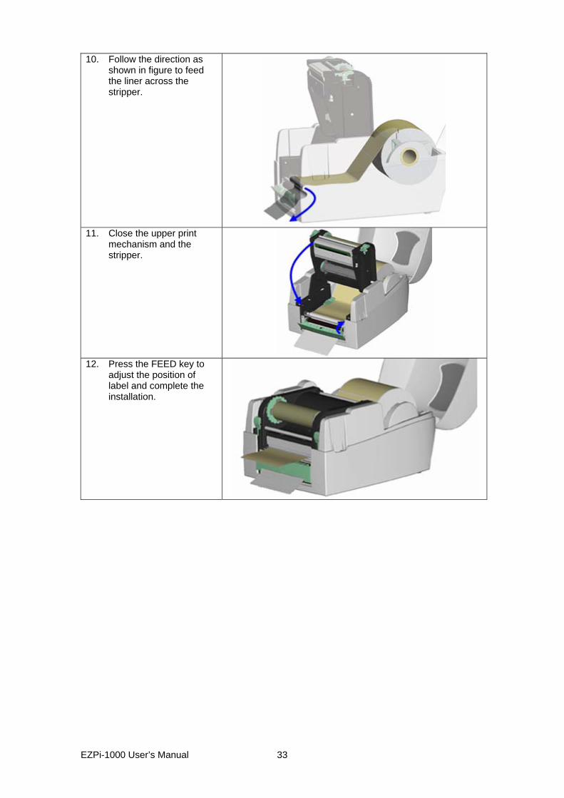
10. Follow the direction as shown in figure to feed the liner across the stripper.
11. Close the upper print
mechanism and the stripper.
12. Press the FEED key to
adjust the position of label and complete the installation.
EZPi-1000 User’s Manual
33
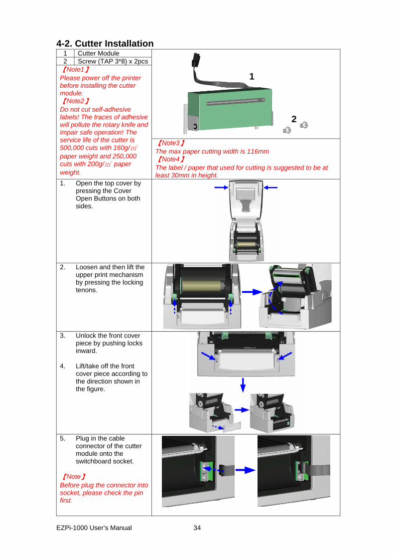
4-2. Cutter Installation 1 Cutter Module 2 Screw (TAP 3*8) x 2pcs
2
1
【Note1】 Please power off the printer before installing the cutter module. 【Note2】 Do not cut self-adhesive labels! The traces of adhesive will pollute the rotary knife and impair safe operation! The service life of the cutter is 500,000 cuts with 160g/㎡ paper weight and 250,000 cuts with 200g/㎡ paper weight.
【Note3】 The max paper cutting width is 116mm 【Note4】 The label / paper that used for cutting is suggested to be at least 30mm in height.
1. Open the top cover by pressing the Cover Open Buttons on both sides.
2. Loosen and then lift the
upper print mechanism by pressing the locking tenons.
3. Unlock the front cover
piece by pushing locks inward.
4. Lift/take off the front
cover piece according to the direction shown in the figure.
5. Plug in the cable
connector of the cutter module onto the switchboard socket.
【Note】 Before plug the connector into socket, please check the pin first.
EZPi-1000 User’s Manual
34
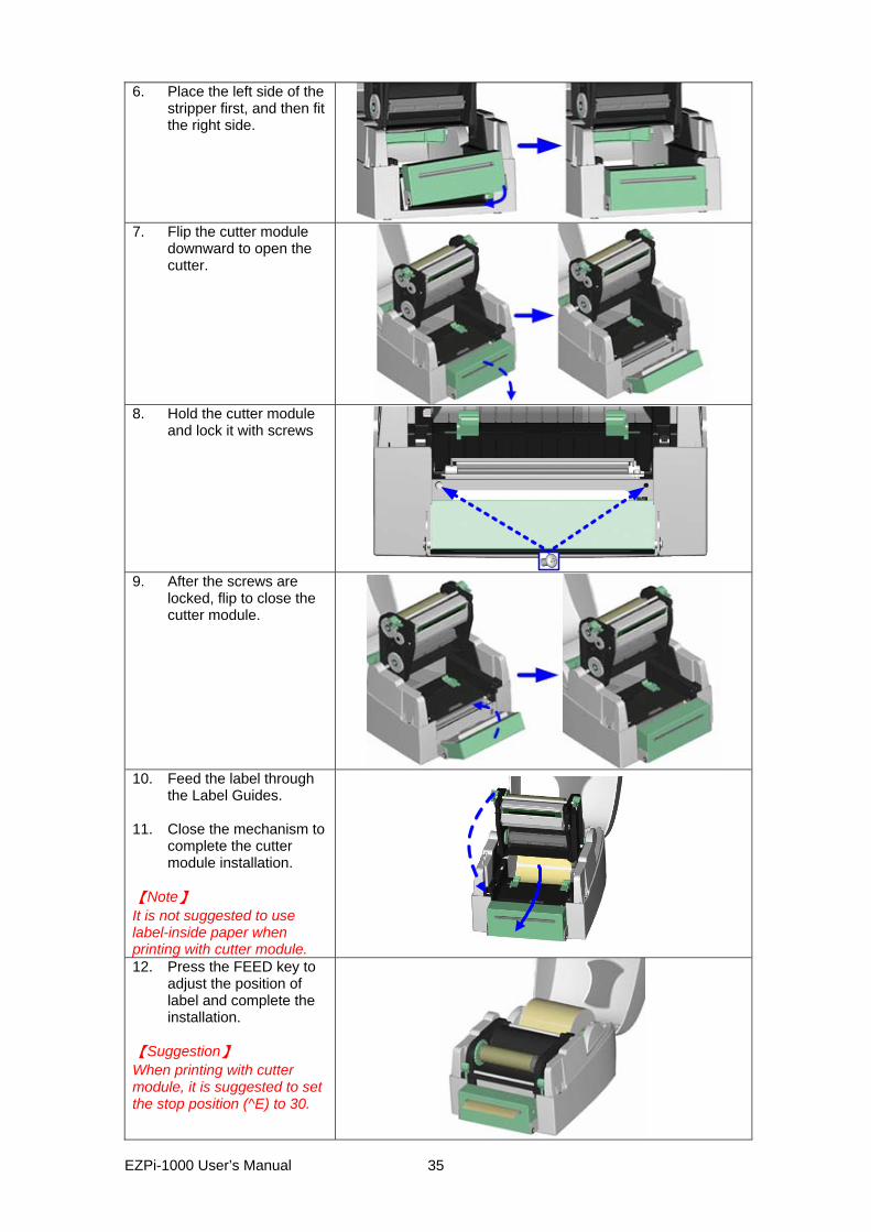
6. Place the left side of the stripper first, and then fit the right side.
7. Flip the cutter module
downward to open the cutter.
8. Hold the cutter module
and lock it with screws
9. After the screws are
locked, flip to close the cutter module.
10. Feed the label through
the Label Guides. 11. Close the mechanism to
complete the cutter module installation.
【Note】 It is not suggested to use label-inside paper when printing with cutter module. 12. Press the FEED key to
adjust the position of label and complete the installation.
【Suggestion】 When printing with cutter module, it is suggested to set the stop position (^E) to 30.
EZPi-1000 User’s Manual
35
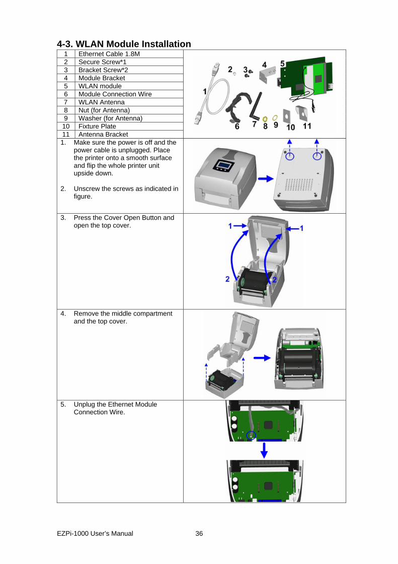
4-3. WLAN Module Installation 1 Ethernet Cable 1.8M 2 Secure Screw*1 3 Bracket Screw*2 4 Module Bracket 5 WLAN module 6 Module Connection Wire
7 WLAN Antenna 8 Nut (for Antenna) 9 Washer (for Antenna) 10 Fixture Plate 11 Antenna Bracket
1. Make sure the power is off and the power cable is unplugged. Place the printer onto a smooth surface and flip the whole printer unit upside down.
2. Unscrew the screws as indicated in
figure.
3. Press the Cover Open Button and
open the top cover.
4. Remove the middle compartment
and the top cover.
5. Unplug the Ethernet Module
Connection Wire.
EZPi-1000 User’s Manual
36
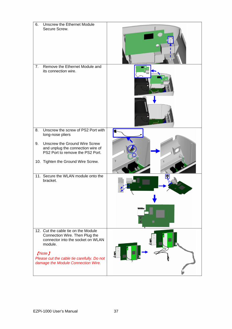
6. Unscrew the Ethernet Module Secure Screw.
7. Remove the Ethernet Module and
its connection wire.
8. Unscrew the screw of PS2 Port with
long-nose pliers 9. Unscrew the Ground Wire Screw
and unplug the connection wire of PS2 Port to remove the PS2 Port.
10. Tighten the Ground Wire Screw.
11. Secure the WLAN module onto the
bracket.
12. Cut the cable tie on the Module
Connection Wire. Then Plug the connector into the socket on WLAN module.
【Note】 Please cut the cable tie carefully. Do not damage the Module Connection Wire.
EZPi-1000 User’s Manual
37
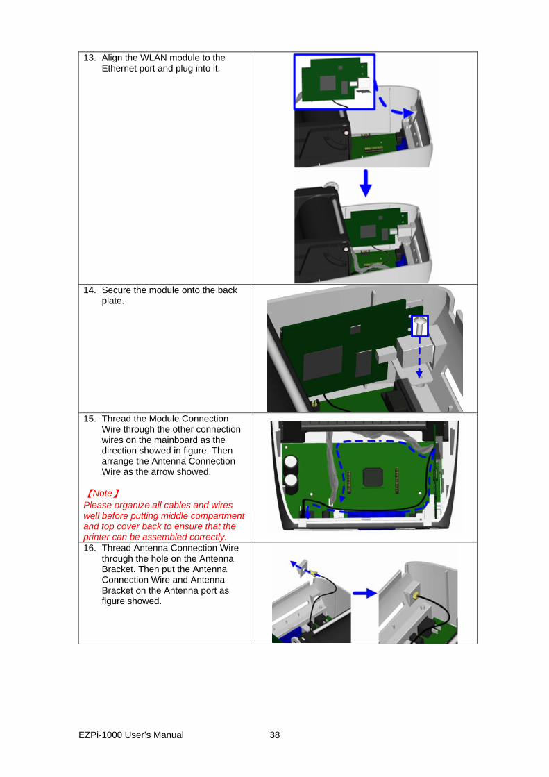
13. Align the WLAN module to the Ethernet port and plug into it.
14. Secure the module onto the back
plate.
15. Thread the Module Connection
Wire through the other connection wires on the mainboard as the direction showed in figure. Then arrange the Antenna Connection Wire as the arrow showed.
【Note】 Please organize all cables and wires well before putting middle compartment and top cover back to ensure that the printer can be assembled correctly.
16. Thread Antenna Connection Wire through the hole on the Antenna Bracket. Then put the Antenna Connection Wire and Antenna Bracket on the Antenna port as figure showed.
EZPi-1000 User’s Manual
38
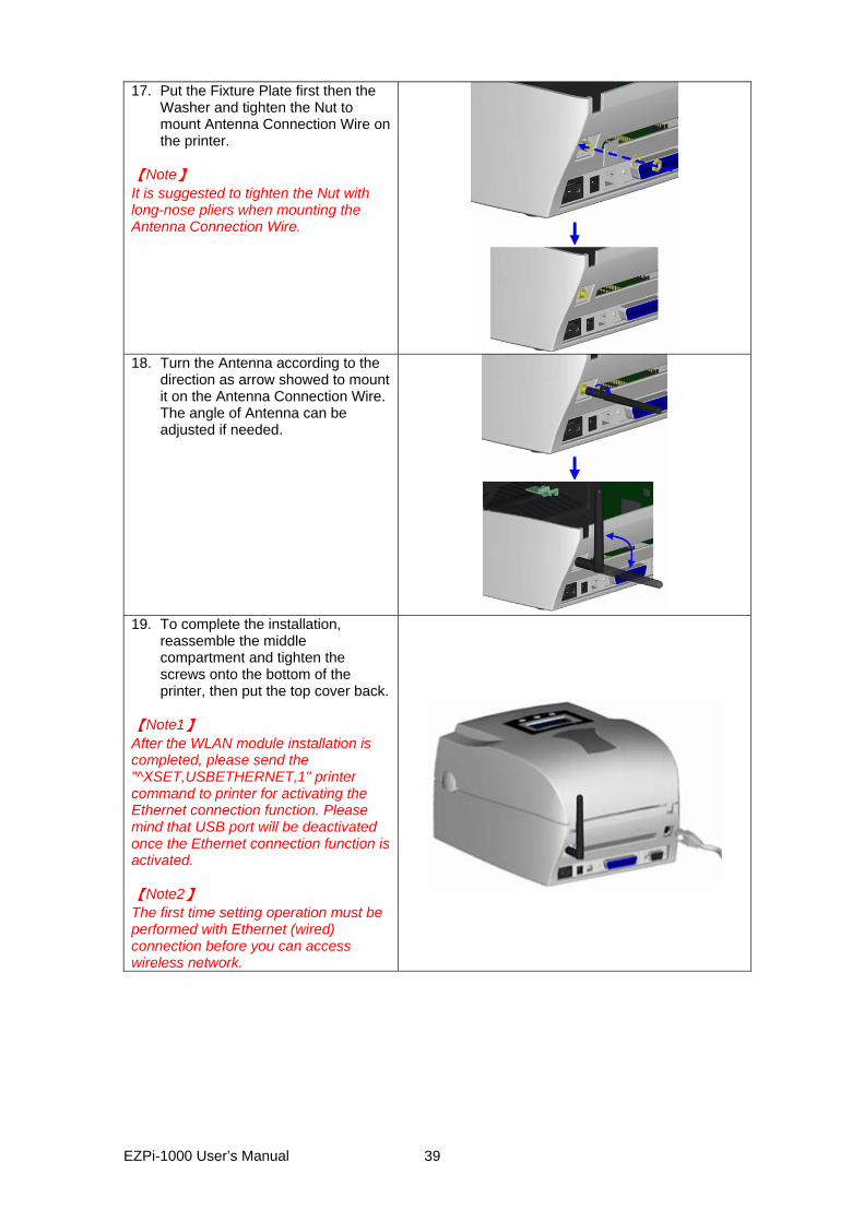
17. Put the Fixture Plate first then the Washer and tighten the Nut to mount Antenna Connection Wire on the printer.
【Note】 It is suggested to tighten the Nut with long-nose pliers when mounting the Antenna Connection Wire.
18. Turn the Antenna according to the
direction as arrow showed to mount it on the Antenna Connection Wire. The angle of Antenna can be adjusted if needed.
19. To complete the installation,
reassemble the middle compartment and tighten the screws onto the bottom of the printer, then put the top cover back.
【Note1】 After the WLAN module installation is completed, please send the "^XSET,USBETHERNET,1" printer command to printer for activating the Ethernet connection function. Please mind that USB port will be deactivated once the Ethernet connection function is activated. 【Note2】 The first time setting operation must be performed with Ethernet (wired) connection before you can access wireless network.
EZPi-1000 User’s Manual
39
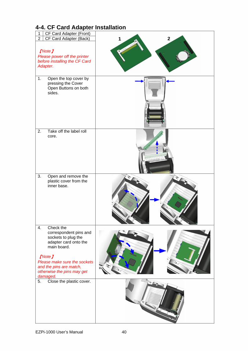
4-4. CF Card Adapter Installation 1 CF Card Adapter (Front) 2 CF Card Adapter (Back)
【Note】 Please power off the printer before installing the CF Card Adapter.
21
1. Open the top cover by
pressing the Cover Open Buttons on both sides.
2. Take off the label roll
core.
3. Open and remove the
plastic cover from the inner base.
4. Check the
correspondent pins and sockets to plug the adapter card onto the main board.
【Note】 Please make sure the sockets and the pins are match, otherwise the pins may get damaged. 5. Close the plastic cover.
EZPi-1000 User’s Manual
40

4-5. CF Card Instruction EZPi-1000 series printers can read the CF Card after installed the CF Card Adapter. If the built-in memory is insufficient for storing label formats, graphics or fonts, users can use CF Card as external memory to provide more memory space. When using the CF card, please follow the instruction as below:
1. Please power off the printer before installing or removing CF Card from the card slot. 2. The CF Card cannot be used for printer’s external memory until it is formatted in
FAT16. When the printer has detected that the CF card is not formatted in FAT16, it will beep 3 times and the Status led light will flash orange.
3. If user wants to format the CF Card, just press the “FEED” key, and then the printer will start to format the CF Card in FAT16. When the format is complete, the LED light will turn to green.
4. If choose not to format the CF Card, just open the Top Cover of printer and wait for the turn-on procedure complete.
5. After the format is complete, a file folder named “Godex” would be created automatically. This folder is for storing all the data from the printer, please don’t do any change on it.
6. The specification of CF Card that is supported by the printer is as follow: Compact Flash Type I Compact Flash (CF) v1.4 specification Capacity: 128MB ~ 1GB File system: FAT16
EZPi-1000 User’s Manual
41
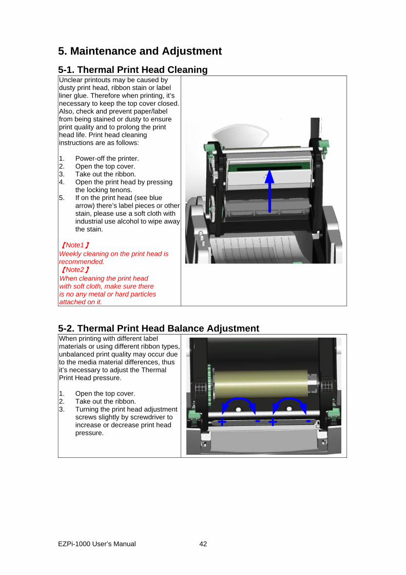
5. Maintenance and Adjustment 5-1. Thermal Print Head Cleaning Unclear printouts may be caused by dusty print head, ribbon stain or label liner glue. Therefore when printing, it’s necessary to keep the top cover closed. Also, check and prevent paper/label from being stained or dusty to ensure print quality and to prolong the print head life. Print head cleaning instructions are as follows: 1. Power-off the printer. 2. Open the top cover. 3. Take out the ribbon. 4. Open the print head by pressing
the locking tenons. 5. If on the print head (see blue
arrow) there’s label pieces or other stain, please use a soft cloth with industrial use alcohol to wipe away the stain.
【Note1】 Weekly cleaning on the print head is recommended. 【Note2】 When cleaning the print head with soft cloth, make sure there is no any metal or hard particles attached on it. 5-2. Thermal Print Head Balance Adjustment When printing with different label materials or using different ribbon types, unbalanced print quality may occur due to the media material differences, thus it’s necessary to adjust the Thermal Print Head pressure. 1. Open the top cover. 2. Take out the ribbon. 3. Turning the print head adjustment
screws slightly by screwdriver to increase or decrease print head pressure.
+ - + -
EZPi-1000 User’s Manual
42
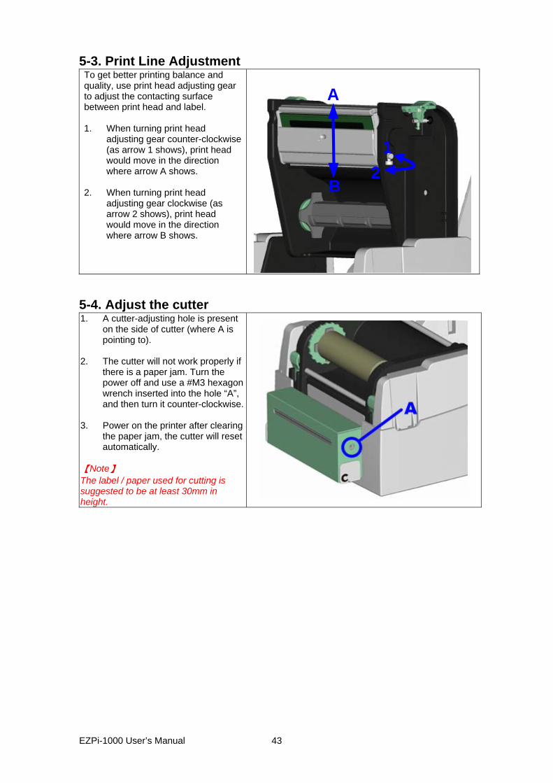
5-3. Print Line Adjustment To get better printing balance and quality, use print head adjusting gear to adjust the contacting surface between print head and label. 1. When turning print head
adjusting gear counter-clockwise (as arrow 1 shows), print head would move in the direction where arrow A shows.
2. When turning print head
adjusting gear clockwise (as arrow 2 shows), print head would move in the direction where arrow B shows.
A
B
12
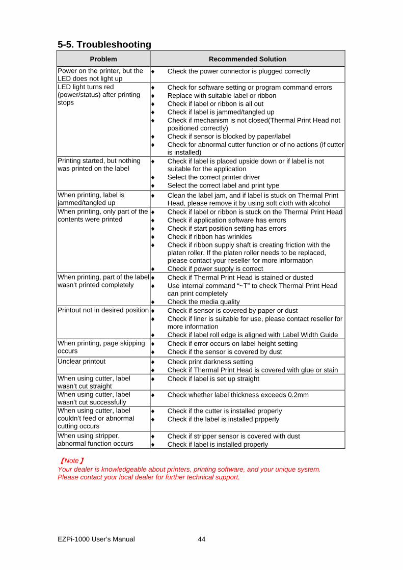
5-4. Adjust the cutter 1. A cutter-adjusting hole is present
on the side of cutter (where A is pointing to).
2. The cutter will not work properly if
there is a paper jam. Turn the power off and use a #M3 hexagon wrench inserted into the hole “A”, and then turn it counter-clockwise.
3. Power on the printer after clearing
the paper jam, the cutter will reset automatically.
【Note】 The label / paper used for cutting is suggested to be at least 30mm in height.
EZPi-1000 User’s Manual
43
5-5. Troubleshooting Problem Recommended Solution
Power on the printer, but the LED does not light up
♦ Check the power connector is plugged correctly
LED light turns red (power/status) after printing stops
♦ Check for software setting or program command errors ♦ Replace with suitable label or ribbon ♦ Check if label or ribbon is all out ♦ Check if label is jammed/tangled up ♦ Check if mechanism is not closed(Thermal Print Head not
positioned correctly) ♦ Check if sensor is blocked by paper/label ♦ Check for abnormal cutter function or of no actions (if cutter
is installed) Printing started, but nothing was printed on the label
♦ Check if label is placed upside down or if label is not suitable for the application
♦ Select the correct printer driver ♦ Select the correct label and print type
When printing, label is jammed/tangled up
♦ Clean the label jam, and if label is stuck on Thermal Print Head, please remove it by using soft cloth with alcohol
When printing, only part of the contents were printed
♦ Check if label or ribbon is stuck on the Thermal Print Head♦ Check if application software has errors ♦ Check if start position setting has errors ♦ Check if ribbon has wrinkles ♦ Check if ribbon supply shaft is creating friction with the
platen roller. If the platen roller needs to be replaced, please contact your reseller for more information
♦ Check if power supply is correct When printing, part of the label wasn’t printed completely
♦ Check if Thermal Print Head is stained or dusted ♦ Use internal command “~T” to check Thermal Print Head
can print completely ♦ Check the media quality
Printout not in desired position ♦ Check if sensor is covered by paper or dust ♦ Check if liner is suitable for use, please contact reseller for
more information ♦ Check if label roll edge is aligned with Label Width Guide
When printing, page skipping occurs
♦ Check if error occurs on label height setting ♦ Check if the sensor is covered by dust
Unclear printout ♦ Check print darkness setting ♦ Check if Thermal Print Head is covered with glue or stain
When using cutter, label wasn’t cut straight
♦ Check if label is set up straight
When using cutter, label wasn’t cut successfully
♦ Check whether label thickness exceeds 0.2mm
When using cutter, label couldn’t feed or abnormal cutting occurs
♦ Check if the cutter is installed properly ♦ Check if the label is installed prpperly
When using stripper, abnormal function occurs
♦ Check if stripper sensor is covered with dust ♦ Check if label is installed properly
【Note】 Your dealer is knowledgeable about printers, printing software, and your unique system. Please contact your local dealer for further technical support.
EZPi-1000 User’s Manual
44