Upcoming Technology in Fiber Optics · Optical Fiber Type 62.5 μm 50 μm 50 μm 50 μm Single-mode...
36
Upcoming Technology & Standards in Fiber Optics Rohit Agrawal Application Engineer
Transcript of Upcoming Technology in Fiber Optics · Optical Fiber Type 62.5 μm 50 μm 50 μm 50 μm Single-mode...
Upcoming Technology & Standards in Fiber Optics
Rohit AgrawalApplication Engineer
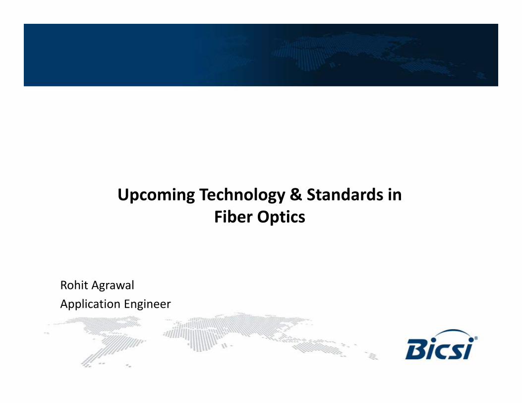
Optical Fiber: composed of at least two optically different materials
corecladding
Buffer coating
• Core: center optical layer of the fiber where the light is transmitted
• Cladding: outside optical layer that traps the light in the core and guides it alone
• Buffer coating: hard plastic coating that protects the glass from moisture or physical damage
Optical Wave Guide
Light Transmission Fundamentals
Electrical to Light Conversion
Light to Electrical
ConversionLED Light Source
Photo-Detector
Electrical Pulse IN
Electrical Pulse OUT
Light Pulse Light Pulse
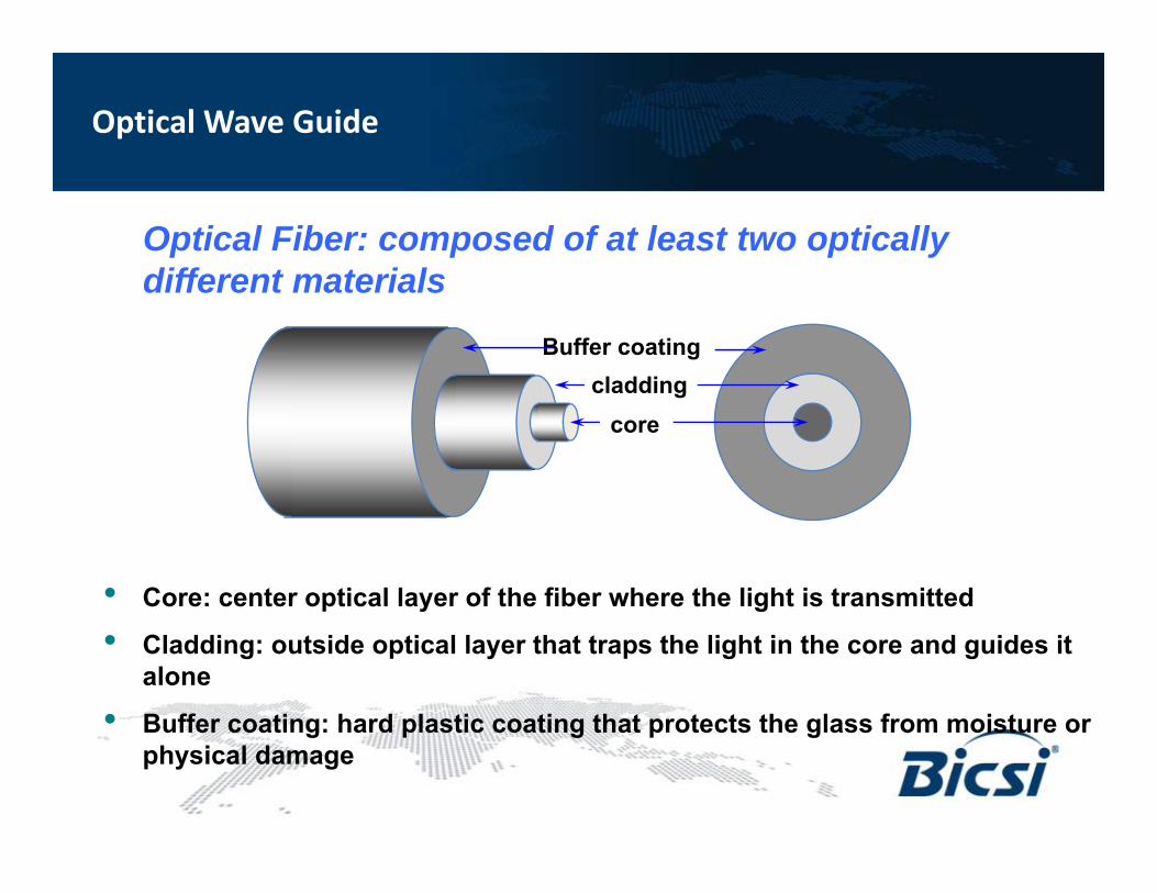
• Electrical Pulse In = Electrical Pulse Out
• Electrical /Optical Conversion on Each End
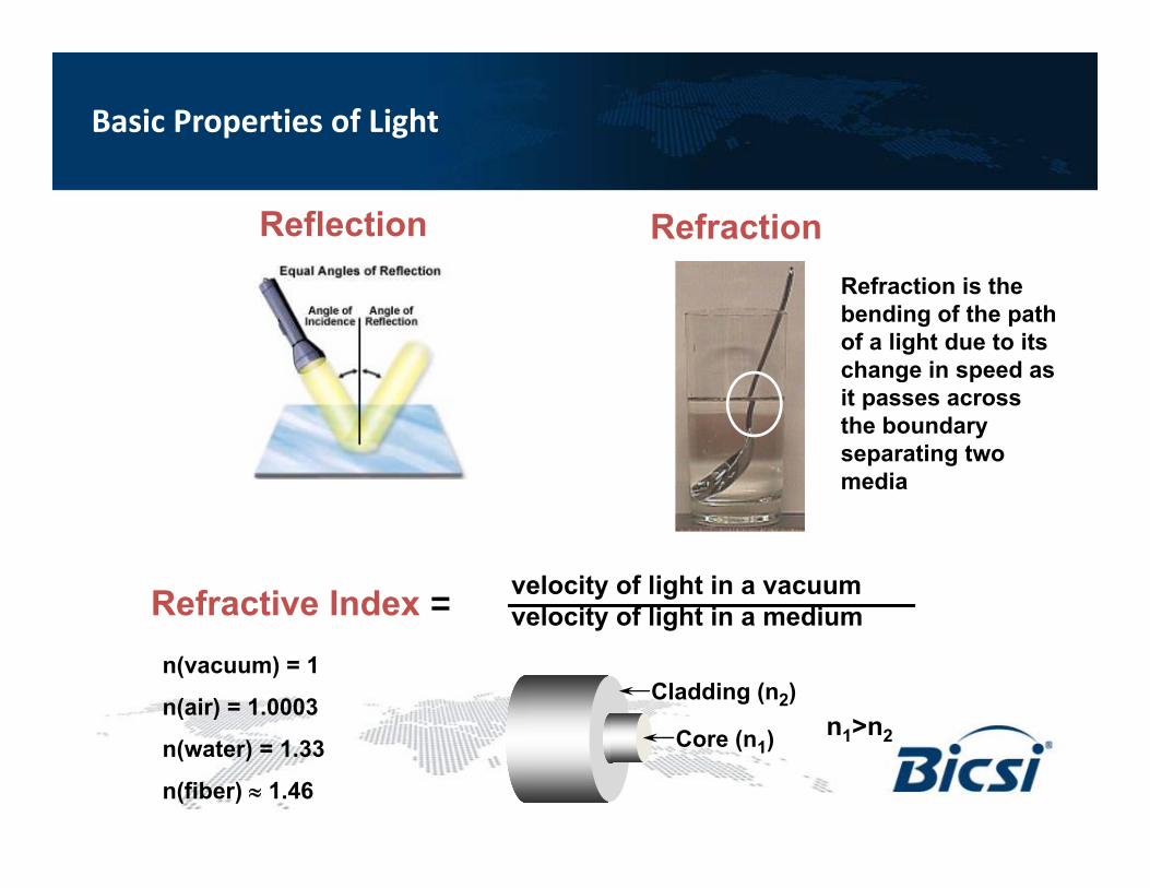
Refraction
velocity of light in a vacuumvelocity of light in a mediumRefractive Index =
ReflectionRefraction is the bending of the path of a light due to its change in speed as it passes across the boundary separating two media
n(vacuum) = 1
n(air) = 1.0003
n(water) = 1.33
n(fiber) 1.46
Cladding (n2)
Core (n1) n1>n2
Basic Properties of Light
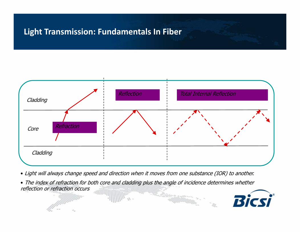
Light Propagation: Total internal reflection is required for light to travel through an optical fiber
Core
Cladding
Cladding
Refraction
Reflection Total Internal Reflection
• Light will always change speed and direction when it moves from one substance (IOR) to another.
• The index of refraction for both core and cladding plus the angle of incidence determines whether reflection or refraction occurs
Light Transmission: Fundamentals In Fiber
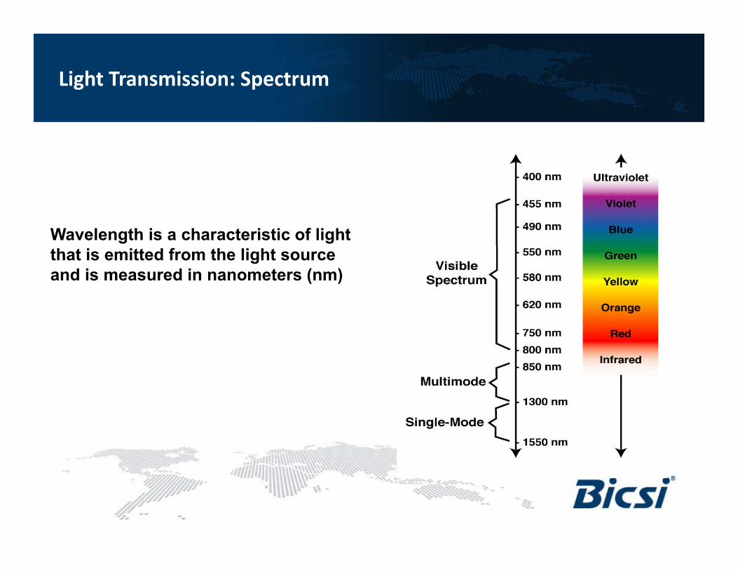
Wavelength is a characteristic of light that is emitted from the light source and is measured in nanometers (nm)
Single-mode
Light Transmission: Spectrum
7
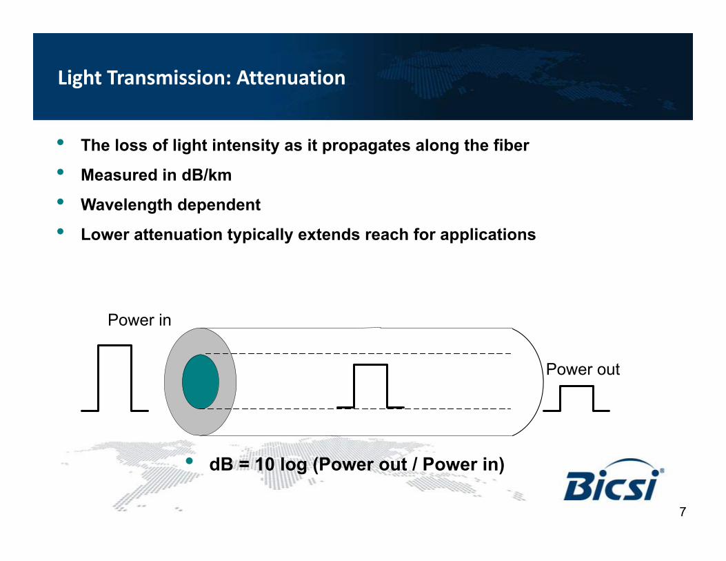
• The loss of light intensity as it propagates along the fiber
• Measured in dB/km
• Wavelength dependent
• Lower attenuation typically extends reach for applications
Power in
Power out
• dB = 10 log (Power out / Power in)
Light Transmission: Attenuation
8
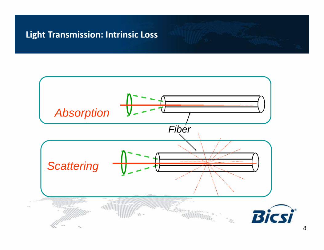
AbsorptionFiber
Scattering
Light Transmission: Intrinsic Loss
9
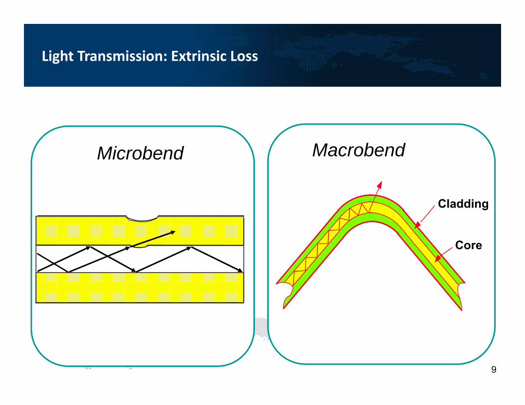
MacrobendMicrobend
Core
Cladding
Light Transmission: Extrinsic Loss
The rule of thumb for minimum bend radius is:
– 30mm for bare, single‐mode fiber
– 10 times the cable’s outside diameter (O.D.) for un‐armored Cable
– 15 times the cable’s O.D. for armored cable
Macro bending Rule of Thumb
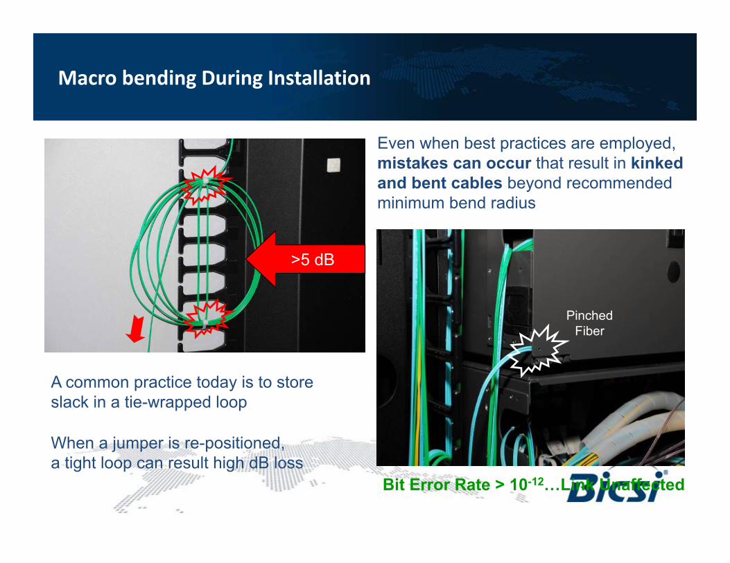
PinchedFiber
Bit Error Rate > 10-12…Link Unaffected
>5 dB
A common practice today is to storeslack in a tie-wrapped loop
When a jumper is re-positioned,a tight loop can result high dB loss
Even when best practices are employed, mistakes can occur that result in kinked and bent cables beyond recommended minimum bend radius
Macro bending During Installation
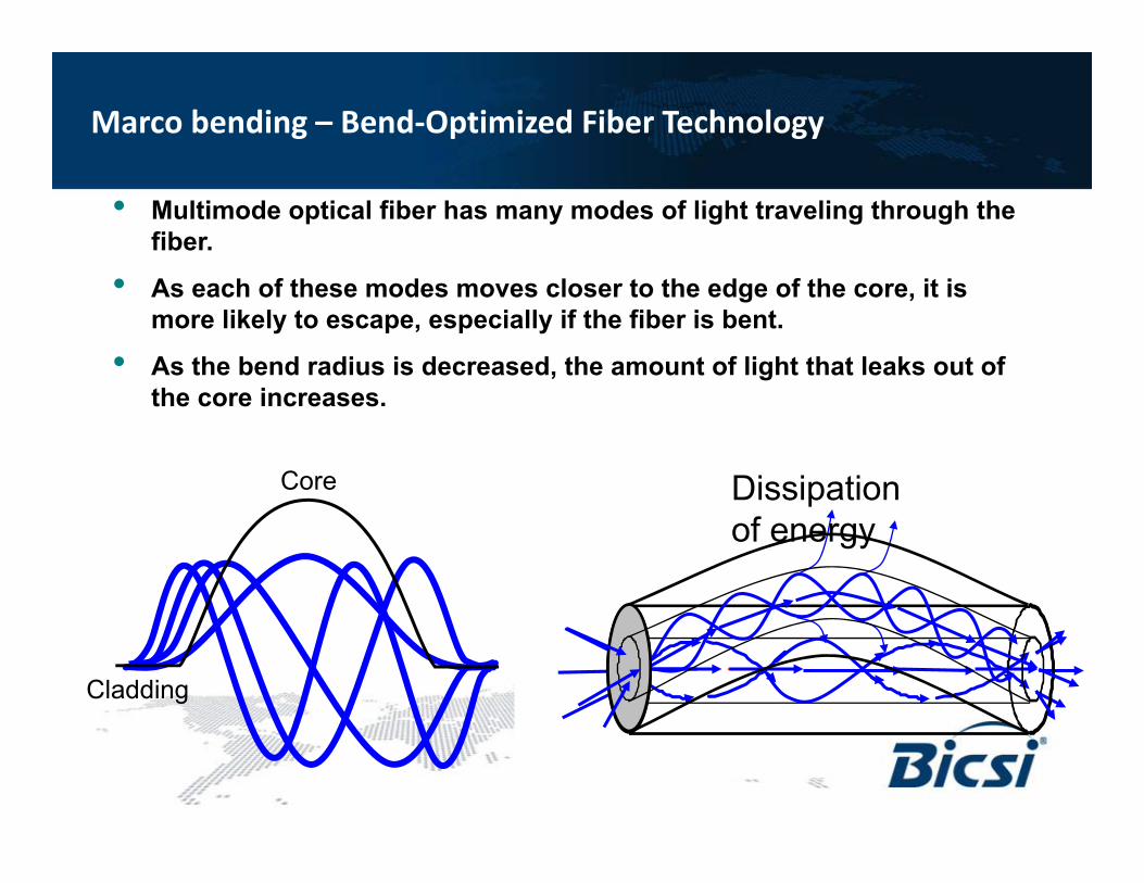
• Multimode optical fiber has many modes of light traveling through the fiber.
• As each of these modes moves closer to the edge of the core, it is more likely to escape, especially if the fiber is bent.
• As the bend radius is decreased, the amount of light that leaks out of the core increases.
Dissipation of energy
Core
Cladding
Marco bending – Bend‐Optimized Fiber Technology
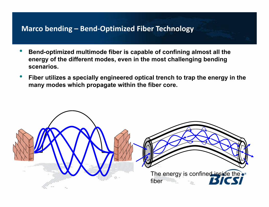
• Bend-optimized multimode fiber is capable of confining almost all the energy of the different modes, even in the most challenging bending scenarios.
• Fiber utilizes a specially engineered optical trench to trap the energy in the many modes which propagate within the fiber core.
The energy is confined inside the fiber
Marco bending – Bend‐Optimized Fiber Technology
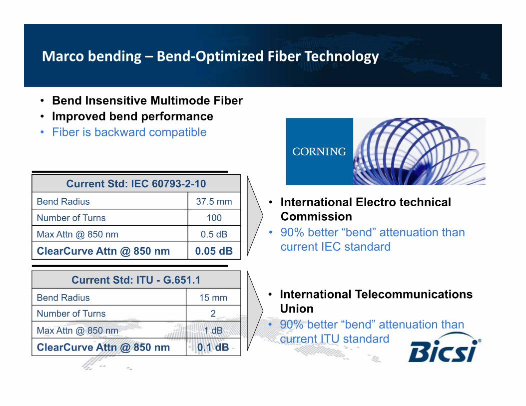
Current Std: ITU - G.651.1Bend Radius 15 mm
Number of Turns 2
Max Attn @ 850 nm 1 dB
ClearCurve Attn @ 850 nm 0.1 dB
Current Std: IEC 60793-2-10Bend Radius 37.5 mm
Number of Turns 100
Max Attn @ 850 nm 0.5 dB
ClearCurve Attn @ 850 nm 0.05 dB
• Bend Insensitive Multimode Fiber • Improved bend performance• Fiber is backward compatible
• International Electro technical Commission
• 90% better “bend” attenuation than current IEC standard
• International Telecommunications Union
• 90% better “bend” attenuation than current ITU standard
Marco bending – Bend‐Optimized Fiber Technology
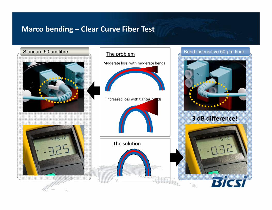
Standard 50 µm fibre
3 dB difference!
Bend insensitive 50 μm fibre
The solution
Moderate loss with moderate bends
The problem
Increased loss with tighter bends
Marco bending – Clear Curve Fiber Test
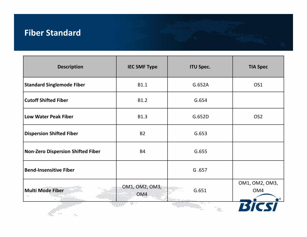
Description IEC SMF Type ITU Spec. TIA Spec
Standard Singlemode Fiber B1.1 G.652A OS1
Cutoff Shifted Fiber B1.2 G.654
Low Water Peak Fiber B1.3 G.652D OS2
Dispersion Shifted Fiber B2 G.653
Non‐Zero Dispersion Shifted Fiber B4 G.655
Bend‐Insensitive Fiber G .657
Multi Mode FiberOM1, OM2, OM3,
OM4G.651
OM1, OM2, OM3, OM4
Fiber Standard
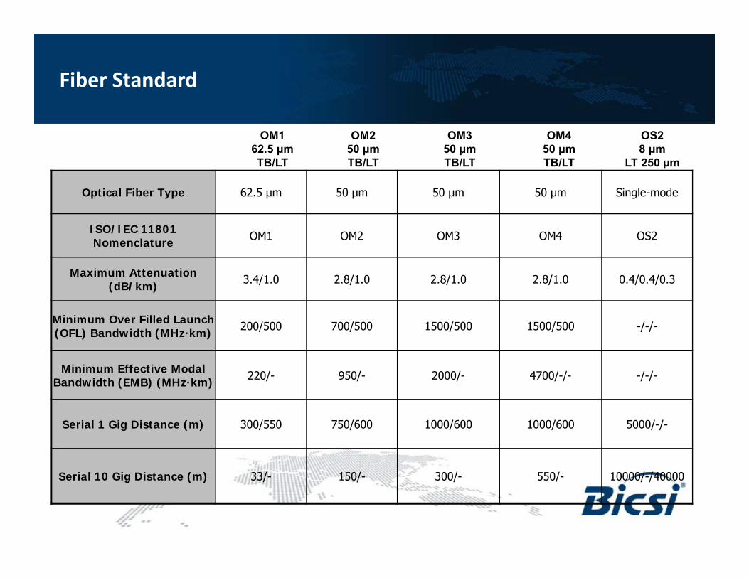
Optical Fiber Type 62.5 μm 50 μm 50 μm 50 μm Single-mode
ISO/IEC 11801 Nomenclature OM1 OM2 OM3 OM4 OS2
Maximum Attenuation (dB/km) 3.4/1.0 2.8/1.0 2.8/1.0 2.8/1.0 0.4/0.4/0.3
Minimum Over Filled Launch (OFL) Bandwidth (MHz·km) 200/500 700/500 1500/500 1500/500 -/-/-
Minimum Effective Modal Bandwidth (EMB) (MHz·km) 220/- 950/- 2000/- 4700/-/- -/-/-
Serial 1 Gig Distance (m) 300/550 750/600 1000/600 1000/600 5000/-/-
Serial 10 Gig Distance (m) 33/- 150/- 300/- 550/- 10000/-/40000
OM162.5 μmTB/LT
OM250 μmTB/LT
OM450 μmTB/LT
OS28 μm
LT 250 µm
OM350 μmTB/LT
Fiber Standard
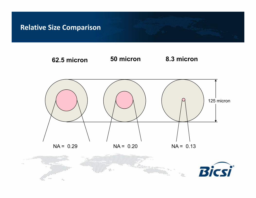
62.5 micron 50 micron 8.3 micron
125 micron
NA = 0.29 NA = 0.20 NA = 0.13
Relative Size Comparison
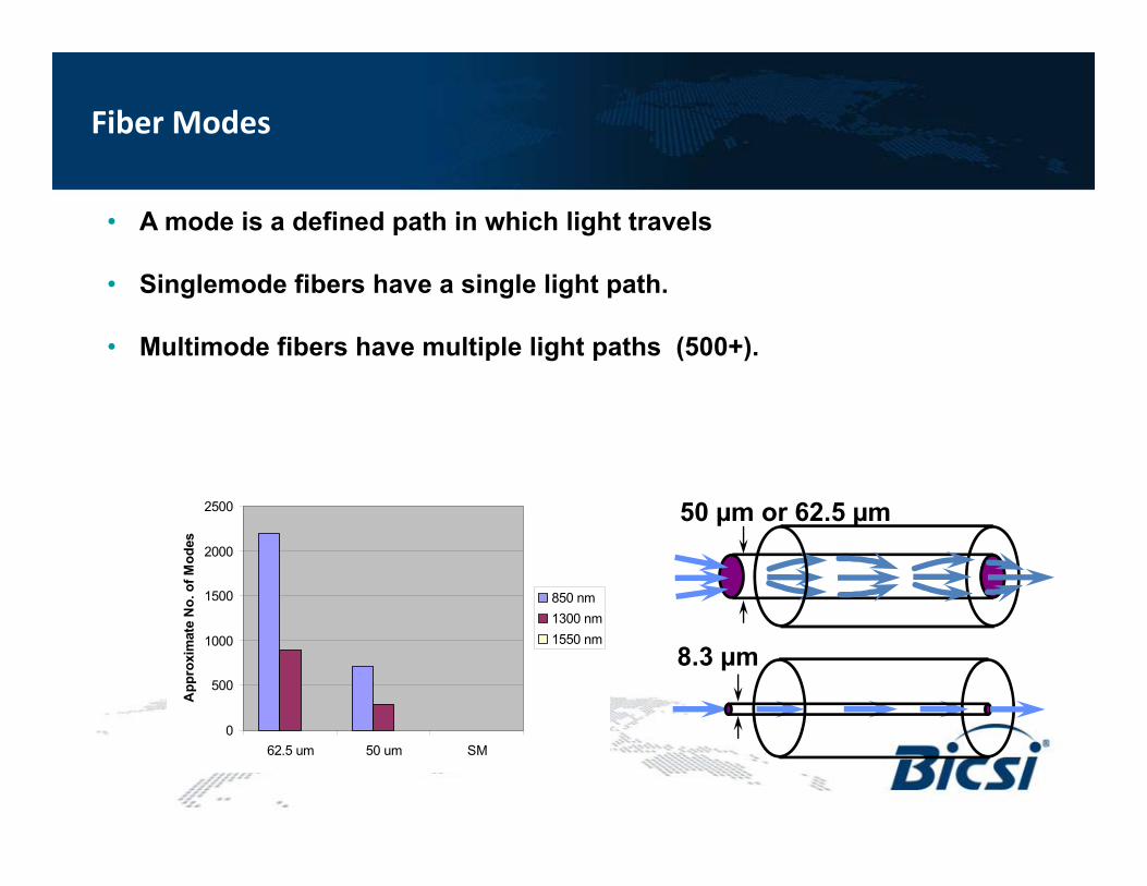
• A mode is a defined path in which light travels
• Singlemode fibers have a single light path.
• Multimode fibers have multiple light paths (500+).
0
500
1000
1500
2000
2500
62.5 um 50 um SM
App
roxi
mat
e N
o. o
f Mod
es
850 nm1300 nm1550 nm
50 µm or 62.5 µm
8.3 µm
Fiber Modes
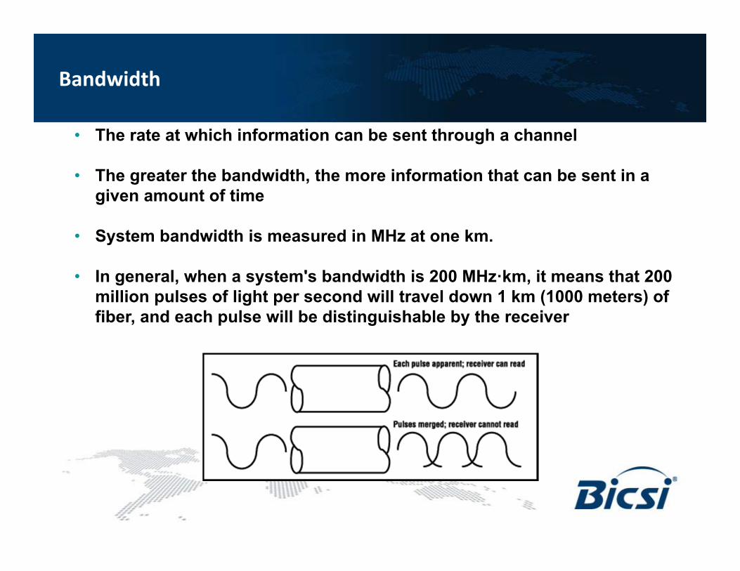
• The rate at which information can be sent through a channel
• The greater the bandwidth, the more information that can be sent in a given amount of time
• System bandwidth is measured in MHz at one km.
• In general, when a system's bandwidth is 200 MHz·km, it means that 200 million pulses of light per second will travel down 1 km (1000 meters) of fiber, and each pulse will be distinguishable by the receiver
Bandwidth
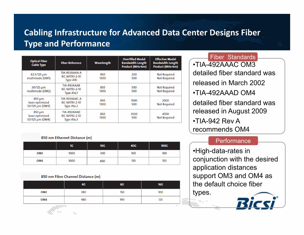
•TIA-492AAAC OM3 detailed fiber standard wasreleased in March 2002•TIA-492AAAD OM4detailed fiber standard was released in August 2009•TIA-942 Rev A recommends OM4
Fiber Standards
Performance•High-data-rates in conjunction with the desiredapplication distances support OM3 and OM4 as the default choice fiber types.
400
Cabling Infrastructure for Advanced Data Center Designs Fiber Type and Performance
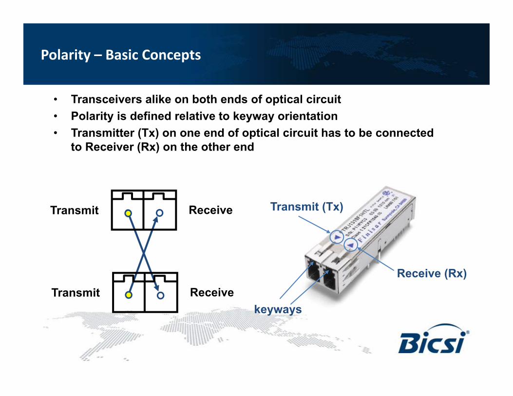
• Transceivers alike on both ends of optical circuit• Polarity is defined relative to keyway orientation• Transmitter (Tx) on one end of optical circuit has to be connected
to Receiver (Rx) on the other end
Transmit (Tx)
Receive (Rx)
keyways
Transmit Receive
Transmit Receive
Polarity – Basic Concepts
Keys
Transmit Receive
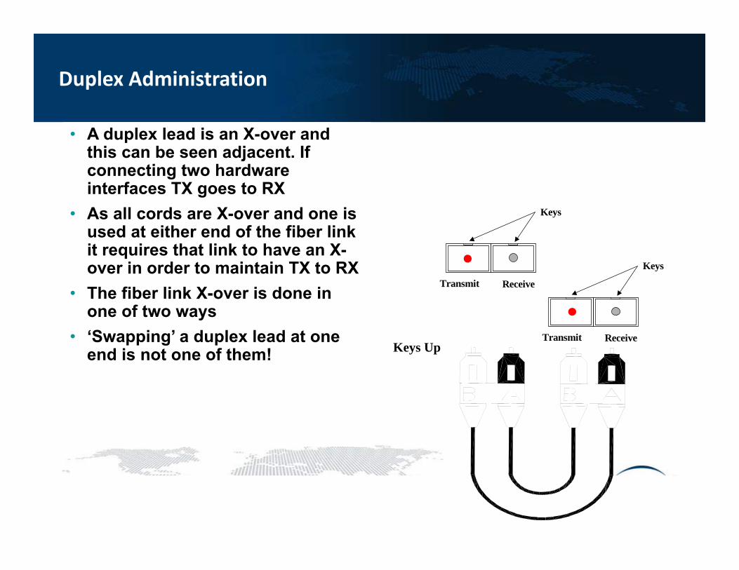
• A duplex lead is an X-over and this can be seen adjacent. If connecting two hardware interfaces TX goes to RX
• As all cords are X-over and one is used at either end of the fiber link it requires that link to have an X-over in order to maintain TX to RX
• The fiber link X-over is done in one of two ways
• ‘Swapping’ a duplex lead at one end is not one of them!
Keys
Transmit Receive
Keys Up
Duplex Administration
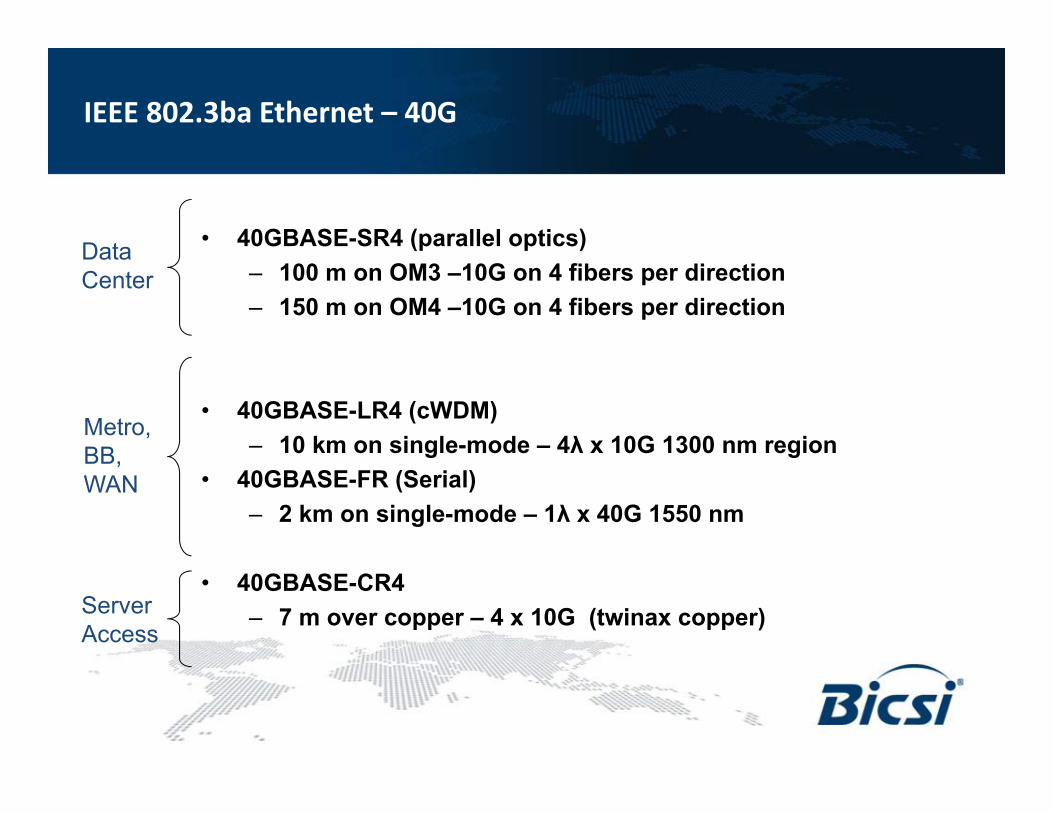
• 40GBASE-SR4 (parallel optics)– 100 m on OM3 –10G on 4 fibers per direction– 150 m on OM4 –10G on 4 fibers per direction
• 40GBASE-LR4 (cWDM)– 10 km on single-mode – 4λ x 10G 1300 nm region
• 40GBASE-FR (Serial)– 2 km on single-mode – 1λ x 40G 1550 nm
• 40GBASE-CR4– 7 m over copper – 4 x 10G (twinax copper)
DataCenter
Metro, BB, WAN
Server Access
IEEE 802.3ba Ethernet – 40G
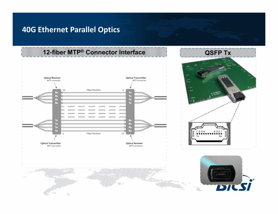
12-fiber MTP® Connector Interface QSFP Tx
40G Ethernet Parallel Optics
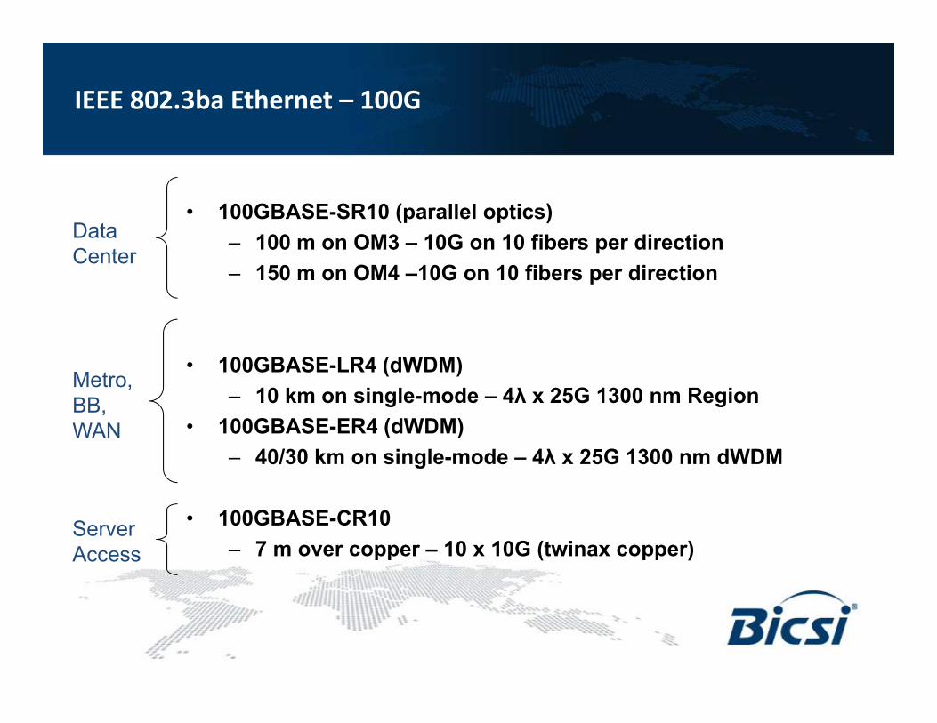
• 100GBASE-SR10 (parallel optics)– 100 m on OM3 – 10G on 10 fibers per direction– 150 m on OM4 –10G on 10 fibers per direction
• 100GBASE-LR4 (dWDM)– 10 km on single-mode – 4λ x 25G 1300 nm Region
• 100GBASE-ER4 (dWDM)– 40/30 km on single-mode – 4λ x 25G 1300 nm dWDM
• 100GBASE-CR10 – 7 m over copper – 10 x 10G (twinax copper)
DataCenter
Metro, BB, WAN
Server Access
IEEE 802.3ba Ethernet – 100G
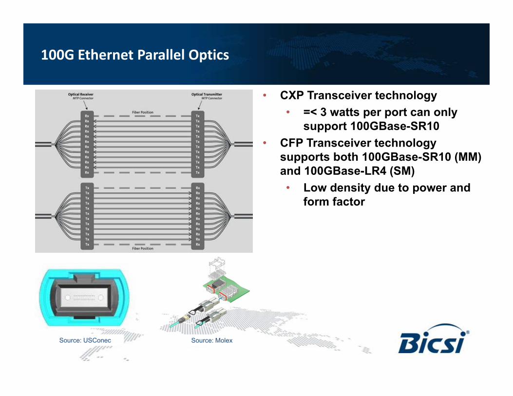
Source: USConec
• CXP Transceiver technology• =< 3 watts per port can only
support 100GBase-SR10• CFP Transceiver technology
supports both 100GBase-SR10 (MM) and 100GBase-LR4 (SM)• Low density due to power and
form factor
Source: Molex
100G Ethernet Parallel Optics
• A Call For Interest (CFI) was approved at the July IEEE 802.3 plenary meeting.– Next Generation 100 Gb/s Optical Ethernet Study Group working to
develop guidance in accordance five criteria stated in PAR– Intent of work in to reduce MMF and SMF cost/power while
increasing line card density.• Considering 4x25G PMDs for both SMF and MMF as an alternative to
10x10G PMD
100G 4‐Lane Solution
Plug & Play Module
MTP-terminated Trunk Cable
Patch Cord
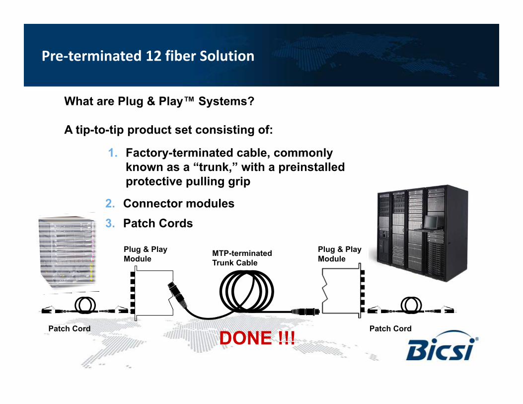
What are Plug & Play™ Systems?
A tip-to-tip product set consisting of:
Plug & Play Module
Patch Cord
1. Factory-terminated cable, commonly known as a “trunk,” with a preinstalled protective pulling grip
2. Connector modules 3. Patch Cords
DONE !!!
Pre‐terminated 12 fiber Solution
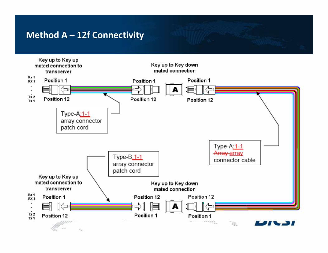
Method A – 12f Connectivity
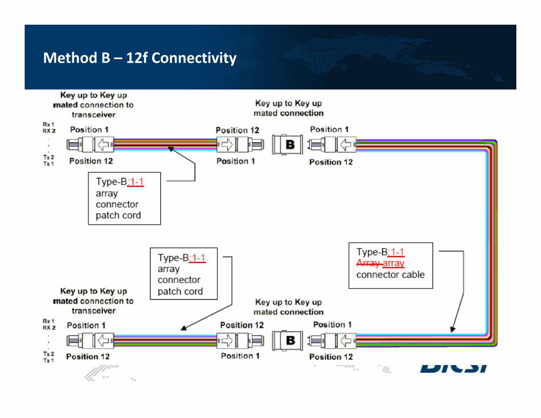
Method B – 12f Connectivity
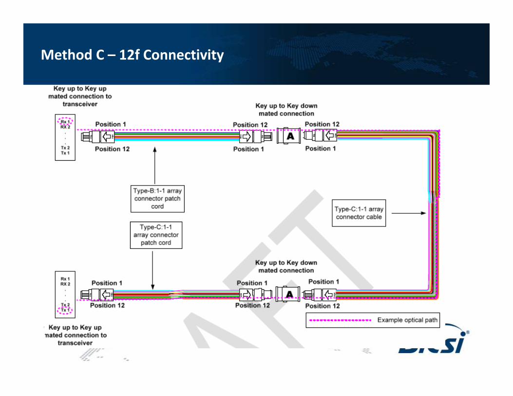
Method C – 12f Connectivity
T
R
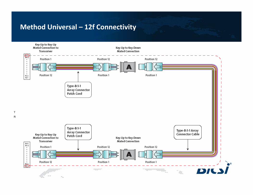
Method Universal – 12f Connectivity
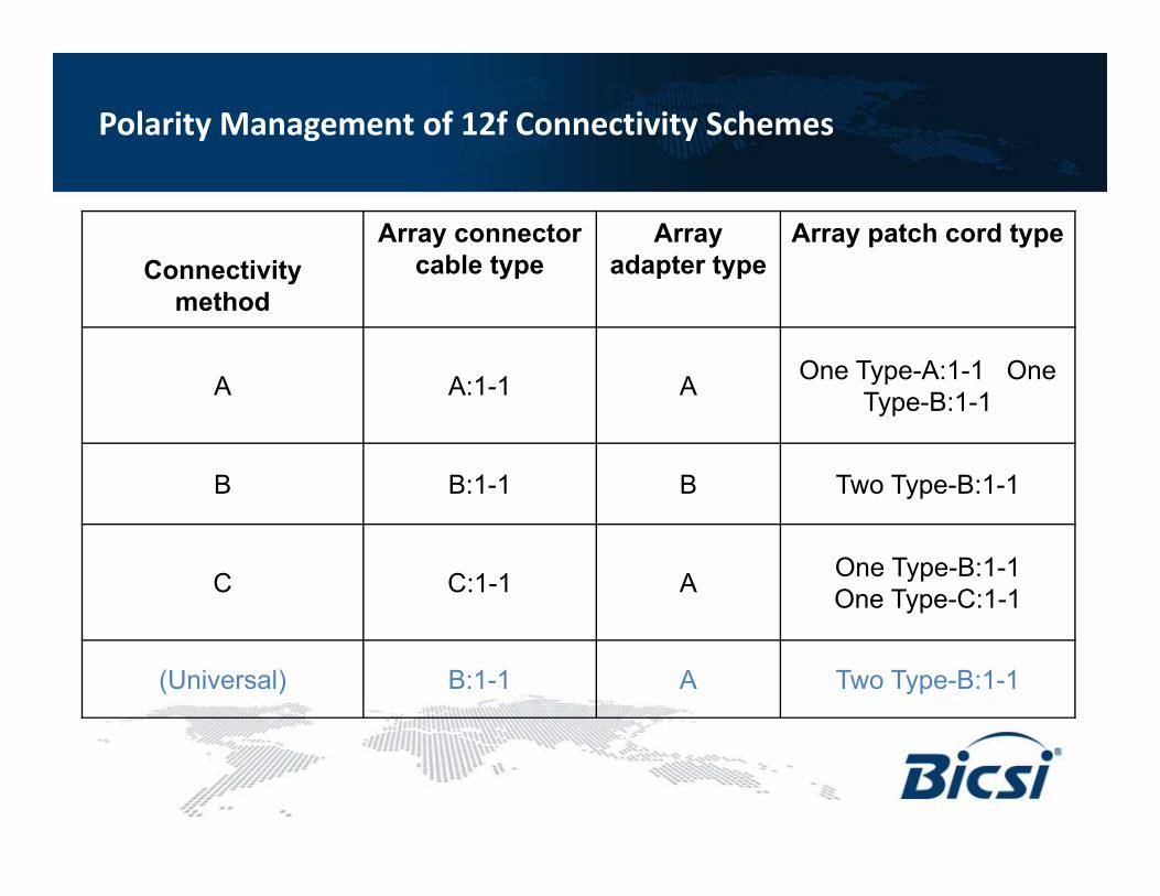
Connectivity method
Array connector cable type
Array adapter type
Array patch cord type
A A:1-1 A One Type-A:1-1 One Type-B:1-1
B B:1-1 B Two Type-B:1-1
C C:1-1 A One Type-B:1-1 One Type-C:1-1
(Universal) B:1-1 A Two Type-B:1-1
Polarity Management of 12f Connectivity Schemes

Duplex LC 10G ports
Duplex LC 10G ports + 12-fiber MPO 40G ports12-fiber MPO 40G ports and/or 24-fiber MPO 100G ports
10G LC modules independently changed out for 40G and/or 100G MPO panels
Optical Connectivity