Eye Safety Constraints for 1.06 μm and 1.55 μm Free … Completed (Closed WGs)/Optical... · 1 ©...
43
1 © CNES 2012 16/04/2012 Eye Safety Constraints for 1.06 μm and 1.55 μm Free Space Optical Communications
Transcript of Eye Safety Constraints for 1.06 μm and 1.55 μm Free … Completed (Closed WGs)/Optical... · 1 ©...
1© CNES 2012
16/04/2012
Eye Safety Constraints for 1.06 μm and 1.55 μm
Free Space Optical Communications
2© CNES 2012
The eye safety constraints are analysed in worst case conditions regarding the risks on eye damage.
Indeed, in the eye safety analysis, the best transmi ssion cases maximizing the power received on the eye surface is considered a s worst case.
Earth observation and telecommunication services based on operational FSOC systems need to comply with eye safety regulations :
The European Comity of Normalization (CEN) defined in its second version of the Norm EN 60825-1 the level of Maximal Permit Exposure (EMP) to lasers. This level is based on the values of the International Commission on Non-Ionizing Radiation protection (ICNIRP). These values were derived from experimental studies and should not be considered as perfect limit. In any case, the CEN norm stress on the fact that exposure to laser has to be as low as possible.
Norme Européenne / Française NF EN 60825-/A11, Séc urité des appareils lasers, juin 2000.
We will deal with the threats that 1.55μm and 1.06μm lasers represent for the human eye in order to derive the constraints on the FSOC system (e.g. in terms of emitted power) and limit distance from the laser path to avoid eye damage.
Introduction
3© CNES 2012
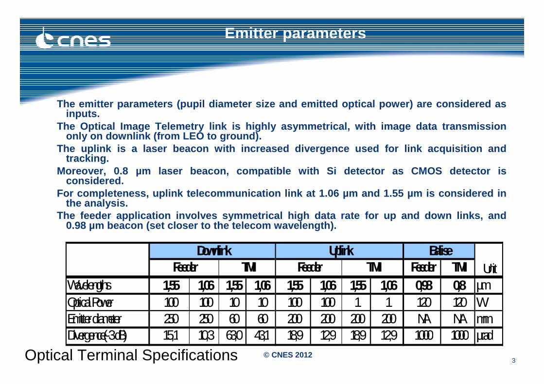
The emitter parameters (pupil diameter size and emi tted optical power) are considered as inputs.
The Optical Image Telemetry link is highly asymmetr ical, with image data transmission only on downlink (from LEO to ground).
The uplink is a laser beacon with increased diverge nce used for link acquisition and tracking.
Moreover, 0.8 µm laser beacon, compatible with Si d etector as CMOS detector is considered.
For completeness, uplink telecommunication link at 1.06 µm and 1.55 µm is considered in the analysis.
The feeder application involves symmetrical high da ta rate for up and down links, and 0.98 µm beacon (set closer to the telecom wavelengt h).
Emitter parameters
Feeder TMIWavelengths 1,55 1,06 1,55 1,06 1,55 1,06 1,55 1,06 0,98 0,8 µmOptical Power 100 100 10 10 100 100 1 1 120 120 WEmitter diameter 250 250 60 60 200 200 200 200 NA NA mmDivergence(-3 dB) 15,1 10,3 63,0 43,1 18,9 12,9 18,9 12,9 1000 1000 µrad
TMIUplink
TMI UnitBaliseDownlink
FeederFeeder
Optical Terminal Specifications
4© CNES 2012
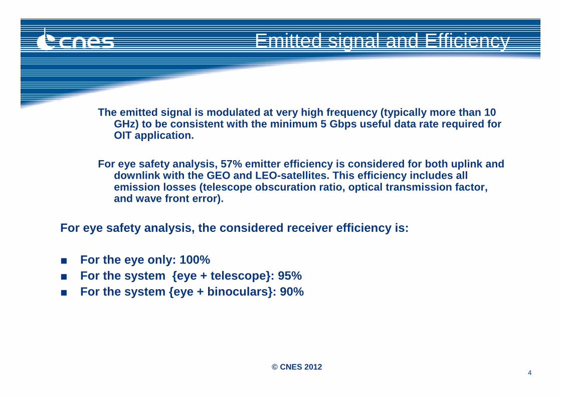
Emitted signal and Efficiency
The emitted signal is modulated at very high freque ncy (typically more than 10 GHz) to be consistent with the minimum 5 Gbps useful data rate required for OIT application.
For eye safety analysis, 57% emitter efficiency is considered for both uplink and downlink with the GEO and LEO-satellites. This effi ciency includes all emission losses (telescope obscuration ratio, optic al transmission factor, and wave front error).
For eye safety analysis, the considered receiver ef ficiency is:
■ For the eye only: 100%■ For the system {eye + telescope}: 95%■ For the system {eye + binoculars}: 90%
5© CNES 2012
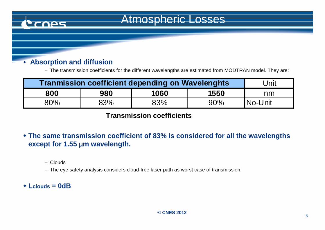
� Absorption and diffusion– The transmission coefficients for the different wavelengths are estimated from MODTRAN model. They are:
Transmission coefficients
� The same transmission coefficient of 83% is conside red for all the wavelengths except for 1.55 μμμμm wavelength.
– Clouds
– The eye safety analysis considers cloud-free laser path as worst case of transmission:
� Lclouds = 0dB
Atmospheric Losses
Unit800 980 1060 1550 nm80% 83% 83% 90% No-Unit
Tranmission coefficient depending on Wavelenghts
6© CNES 2012
Atmospheric losses Sintillations (1)
ScintillationThe wind is a turbulent flow of air generating random fluctuations of the optical index of air.
Thus, the optical wavefront propagating through the atmosphere is distorted, causing scintillation at the receiver level.
Signal fluctuation probability The scintillation leads to quick variation of the signal strength. It decreases the average signal intensity Io
but can also lead to temporary maximum by constructive interferences which may be dangerous for the eye. This stochastic complex phenomenon depends on:
- The turbulence profile of the stratosphere (diurnal and time varying);- The wavelength;- The path distance in the stratosphere (depending on the elevation angle);- The receiver aperture (averaging effect).
The normalized signal intensity variation due to scintillation follows a log-normal probability density function with a mean value of 1 (because of normalization I/Io) and a variance (related to the scintillation index SI) characteristic of the scintillation strength. Several models exist to compute the scintillation variance for low scintillation turbulence (Rytov approximation). Equations also exist to compute the scintillation variance for high turbulence from low turbulence results. Once the scintillation variance is estimated, the log-normal probability density function of the signal intensity is obtained.
More details in the ANNEXE 1
7© CNES 2012
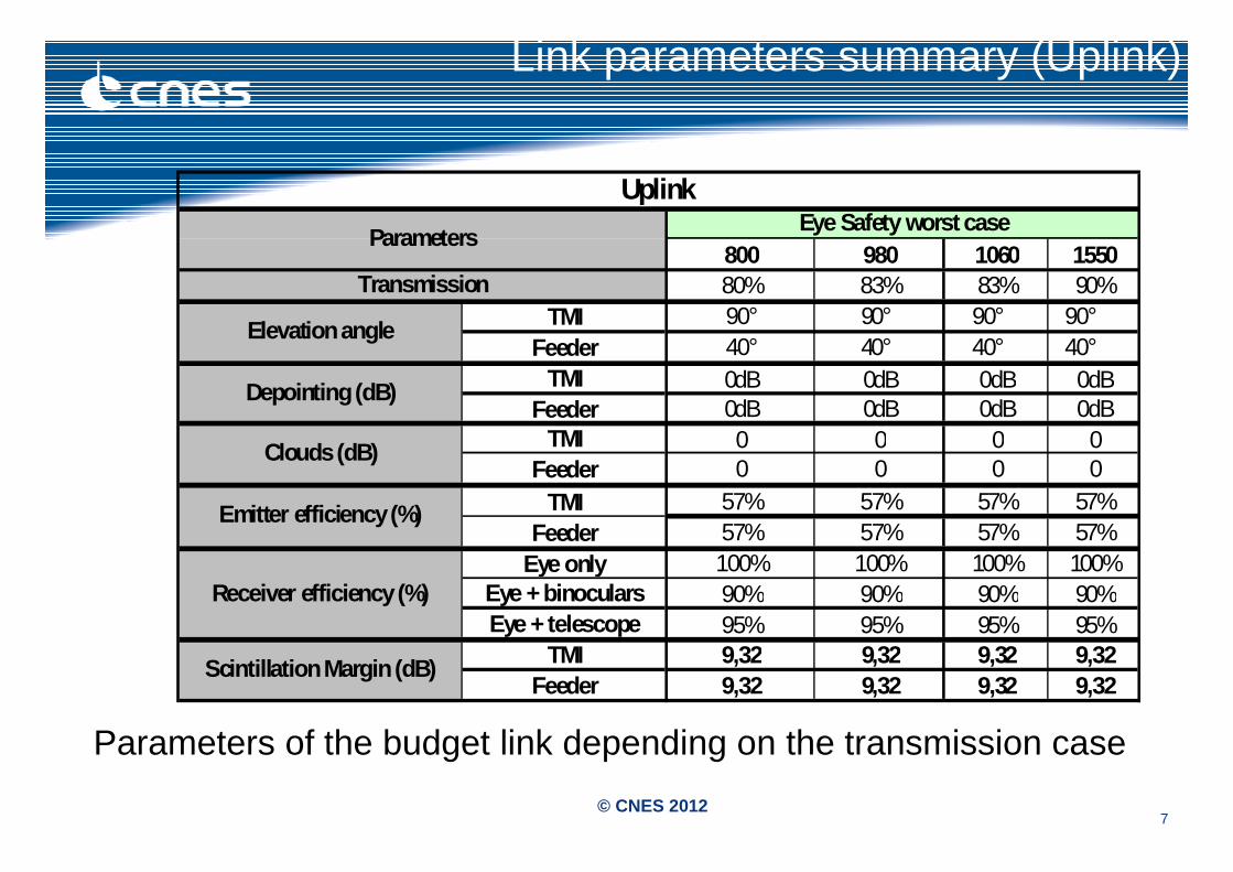
Link parameters summary (Uplink)
800 980 1060 155080% 83% 83% 90%
TMI 90° 90° 90° 90°Feeder 40° 40° 40° 40°
TMI 0dB 0dB 0dB 0dBFeeder 0dB 0dB 0dB 0dB
TMI 0 0 0 0Feeder 0 0 0 0
TMI 57% 57% 57% 57%Feeder 57% 57% 57% 57%
Eye only 100% 100% 100% 100%Eye + binoculars 90% 90% 90% 90%Eye + telescope 95% 95% 95% 95%
TMI 9,32 9,32 9,32 9,32Feeder 9,32 9,32 9,32 9,32
Uplink
Clouds (dB)
Scintillation Margin (dB)
Depointing (dB)
Elevation angle
Eye Safety worst case
Receiver efficiency (%)
Emitter efficiency (%)
Transmission
Parameters
Parameters of the budget link depending on the transmission case
8© CNES 2012
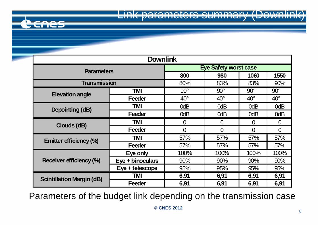
Link parameters summary (Downlink)
800 980 1060 155080% 83% 83% 90%
TMI 90° 90° 90° 90°Feeder 40° 40° 40° 40°
TMI 0dB 0dB 0dB 0dBFeeder 0dB 0dB 0dB 0dB
TMI 0 0 0 0Feeder 0 0 0 0
TMI 57% 57% 57% 57%Feeder 57% 57% 57% 57%
Eye only 100% 100% 100% 100%Eye + binoculars 90% 90% 90% 90%Eye + telescope 95% 95% 95% 95%
TMI 6,91 6,91 6,91 6,91Feeder 6,91 6,91 6,91 6,91
Scintillation Margin (dB)
Clouds (dB)
Emitter efficiency (%)
Elevation angle
Transmission
Receiver efficiency (%)
Downlink
Depointing (dB)
ParametersEye Safety worst case
Parameters of the budget link depending on the transmission case
9© CNES 2012
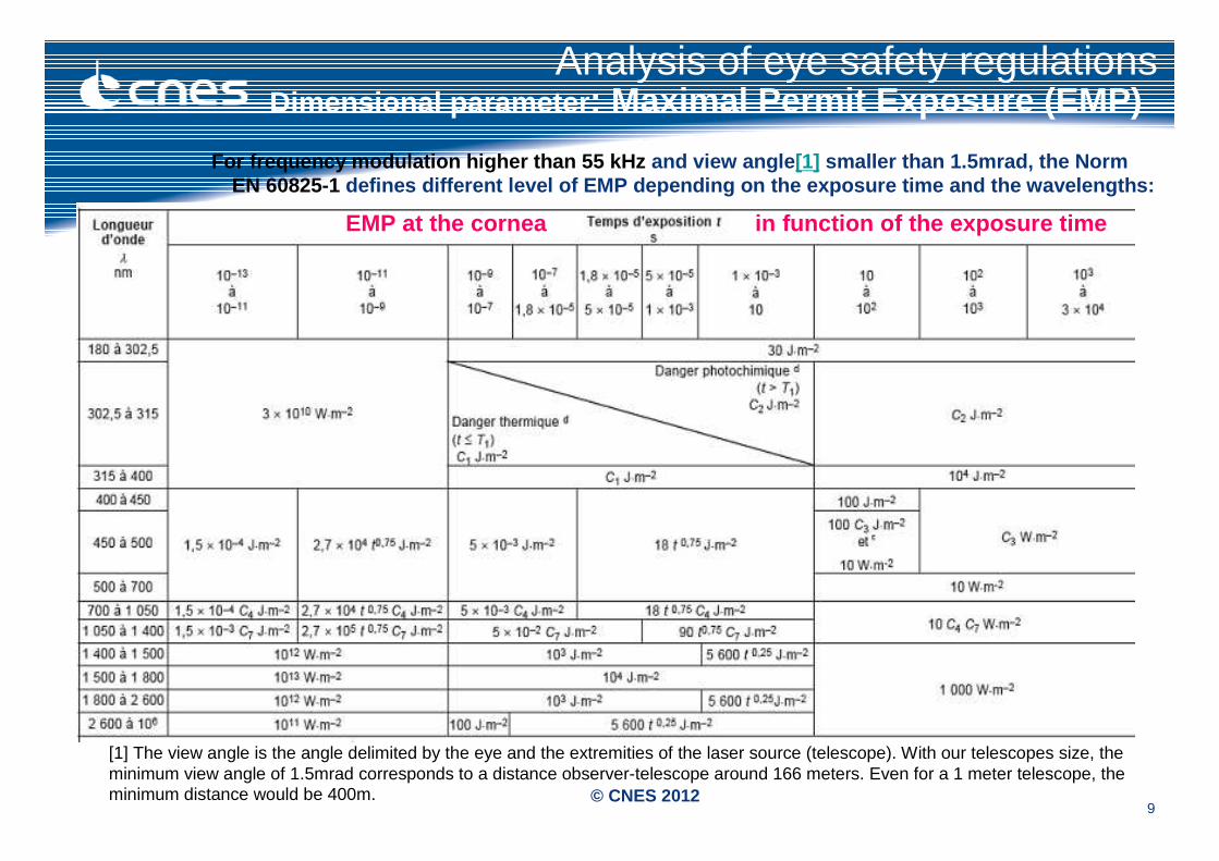
For frequency modulation higher than 55 kHz and view angle [1] smaller than 1.5mrad, the Norm EN 60825-1 defines different level of EMP depending on the exp osure time and the wavelengths:
Analysis of eye safety regulations
[1] The view angle is the angle delimited by the eye and the extremities of the laser source (telescope). With our telescopes size, the minimum view angle of 1.5mrad corresponds to a distance observer-telescope around 166 meters. Even for a 1 meter telescope, the minimum distance would be 400m.
EMP at the cornea in function of the exposure time
Dimensional parameter : Maximal Permit Exposure (EMP)
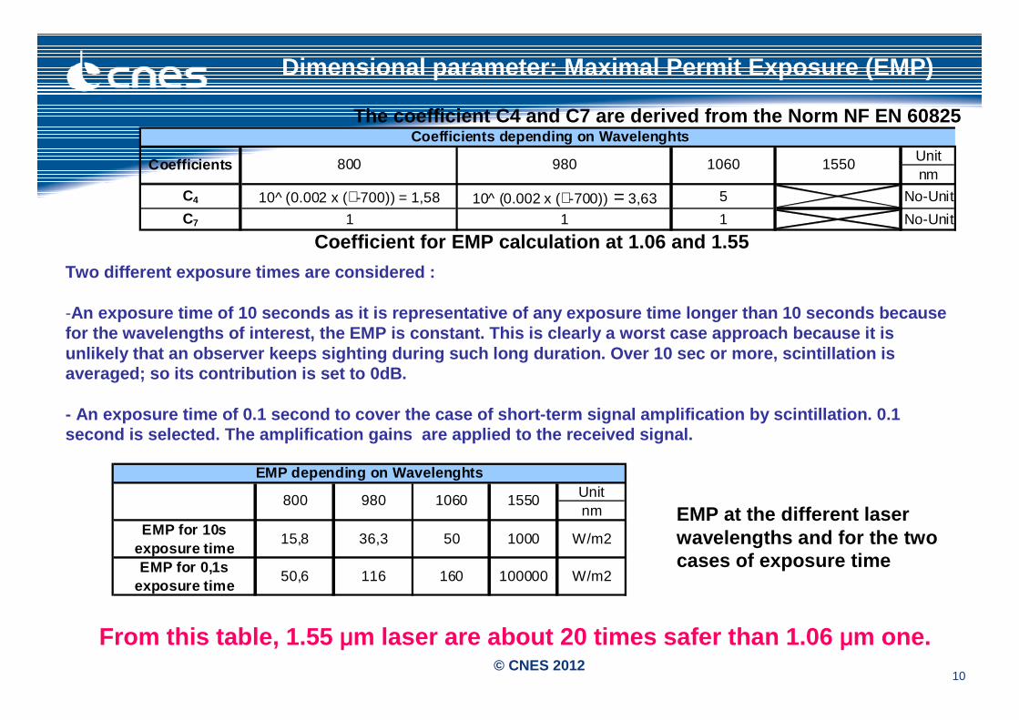
10© CNES 2012
Unitnm
C4 10^ (0.002 x (∠-700)) = 1,58 10^ (0.002 x (∠-700)) = 3,63 5 No-Unit
C7 1 1 1 No-Unit
Coefficients depending on Wavelenghts
Coefficients 800 980 1060 1550
The coefficient C4 and C7 are derived from the Norm NF EN 60825
Coefficient for EMP calculation at 1.06 and 1.55
Two different exposure times are considered :
-An exposure time of 10 seconds as it is representat ive of any exposure time longer than 10 seconds beca use for the wavelengths of interest, the EMP is constan t. This is clearly a worst case approach because it is unlikely that an observer keeps sighting during suc h long duration. Over 10 sec or more, scintillation is averaged; so its contribution is set to 0dB.
- An exposure time of 0.1 second to cover the case o f short-term signal amplification by scintillation. 0.1 second is selected. The amplification gains are ap plied to the received signal.
EMP at the different laser wavelengths and for the two cases of exposure time
Unitnm
EMP for 10s exposure time
15,8 36,3 50 1000 W/m2
EMP for 0,1sexposure time
50,6 116 160 100000 W/m2
980 1060 1550
EMP depending on Wavelenghts
800
From this table, 1.55 μμμμm laser are about 20 times safer than 1.06 μμμμm one.
Dimensional parameter: Maximal Permit Exposure (EMP)
11© CNES 2012
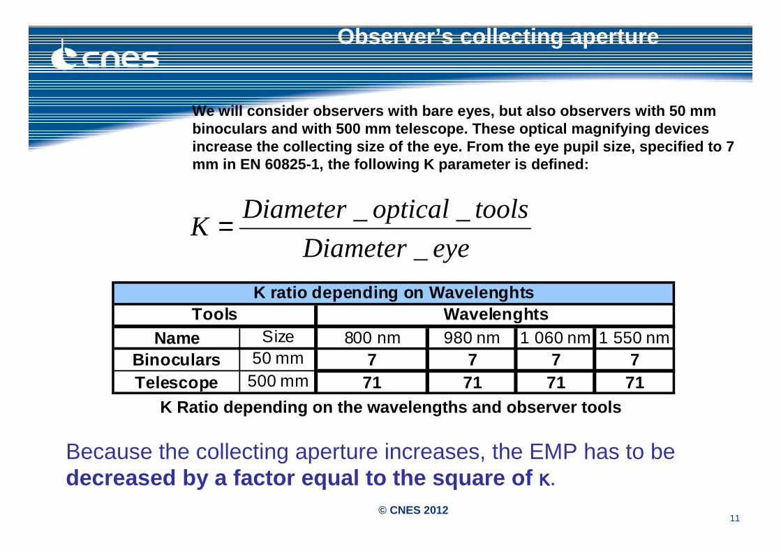
Observer ’s collecting aperture
We will consider observers with bare eyes, but also observers with 50 mm binoculars and with 500 mm telescope. These optical magnifying devices increase the collecting size of the eye. From the e ye pupil size, specified to 7 mm in EN 60825-1, the following K parameter is defi ned:
eyeDiameter
toolsopticalDiameterK
_
__=
Name 800 nm 980 nm 1 060 nm 1 550 nmBinoculars 7 7 7 7Telescope 71 71 71 71
WavelenghtsK ratio depending on Wavelenghts
50 mm500 mm
SizeTools
K Ratio depending on the wavelengths and observer tools
Because the collecting aperture increases, the EMP has to be decreased by a factor equal to the square of κκκκ.
12© CNES 2012
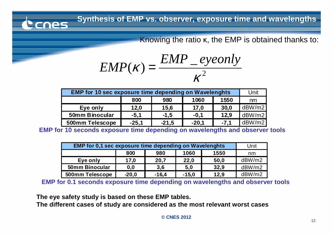
Synthesis of EMP vs. observer, exposure time and wavel engths
Knowing the ratio κ, the EMP is obtained thanks to:
2
_)(
κκ eyeonlyEMP
EMP =
Unit800 980 1060 1550 nm
Eye only 12,0 15,6 17,0 30,0 dBW/m250mm Binocular -5,1 -1,5 -0,1 12,9 dBW/m2
500mm Telescope -25,1 -21,5 -20,1 -7,1 dBW/m2
EMP for 10 sec exposure time depending on Wavelengh ts
EMP for 10 seconds exposure time depending on wavel engths and observer tools
Unit800 980 1060 1550 nm
Eye only 17,0 20,7 22,0 50,0 dBW/m250mm Binocular 0,0 3,6 5,0 32,9 dBW/m2
500mm Telescope -20,0 -16,4 -15,0 12,9 dBW/m2
EMP for 0,1 sec exposure time depending on Waveleng hts
EMP for 0.1 seconds exposure time depending on wave lengths and observer tools
The eye safety study is based on these EMP tables. The different cases of study are considered as the most relevant worst cases
13© CNES 2012
Eye safety study cases (1)
1) Observer close to the OGS
The observer is on Earth close to the OGS looking a t the Laser Communication Terminal (LCT) on board the GEO/LEO satellite. The distances between the observer and the LCT are:
LEO: 700 km; GEO: 38450 km.
Only the downlink is considered with a duration of exposition of 10 sec and 0.1 sec.
2) Observer with binocular close to the OGS
Now, the observer uses binoculars. Binoculars incre ase the collecting aperture size for photons and so the EMP is lower than for t he previous case.
Even if the collecting aperture size increases, the scintillation effect does not change because we are at saturation level.
14© CNES 2012
Eye safety study cases (2)
3) Aircraft crossing the laser path
In this case, an airplane flying at 10km altitude and crossing the laser beam is firstly considered. In this context, 10 sec and 0.1 sec time exposures are taken into account (10 sec illumination is not realistic for an airplane, but covers the case of aircraft in stationary flight (e.g. a helicopter)). Uplink and downlink are analysed.
Secondly, a parameters analysis presents exclusion zones for stationary aircrafts (e.g. helicopter) and for non-stationary airplanes.
The range of optical emitted power goes from 1W to very high power optical links such as 300W.
15© CNES 2012
4) Astronaut sighting the laser source with telesco pe
In this case, an astronaut on board a spatial vehicle on LEO orbit (e.g. Space Station at 400km altitude) is considered. The minimum distance to the laser emitter depends on the respective orbits:
■ ~35000 km for GEO-astronaut (downlink);■ 300 km for LEO-astronaut (downlink);■ 400 km for ground-to-astronaut (uplinks to the GEO and t he LEO
satellites). ■ As the telescope increases the collecting size for p hotons, the EMP is
lower than for the previous case. As for the binoculars cases, the scintillation effect does not change because we are at saturation level.
Eye safety study cases (3)
16© CNES 2012
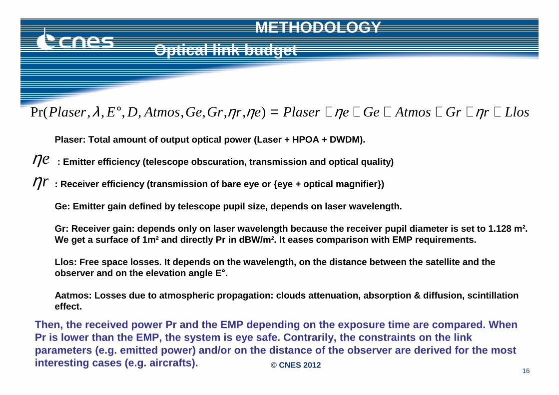
METHODOLOGYOptical link budget
LlosrGrAtmosGeePlasererGrGeAtmosDEPlaser ++++++=° ηηηηλ ),,,,,,,,Pr(
Plaser: Total amount of output optical power (Laser + HPOA + DWDM).
: Emitter efficiency (telescope obscuration, transm ission and optical quality)
: Receiver efficiency (transmission of bare eye or {eye + optical magnifier})
Ge: Emitter gain defined by telescope pupil size, d epends on laser wavelength.
Gr: Receiver gain: depends only on laser wavelength because the receiver pupil diameter is set to 1.12 8 m². We get a surface of 1m² and directly Pr in dBW/m². I t eases comparison with EMP requirements.
Llos: Free space losses. It depends on the waveleng th, on the distance between the satellite and the observer and on the elevation angle E °°°°.
Aatmos: Losses due to atmospheric propagation: clou ds attenuation, absorption & diffusion, scintillati on effect.
eηrη
Then, the received power Pr and the EMP depending o n the exposure time are compared. When Pr is lower than the EMP, the system is eye safe. C ontrarily, the constraints on the link parameters (e.g. emitted power) and/or on the dista nce of the observer are derived for the most interesting cases (e.g. aircrafts).
17© CNES 2012
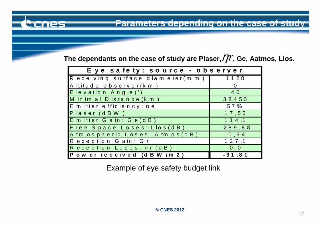
Parameters depending on the case of study
The dependants on the case of study are Plaser, , Ge, Aatmos, Llos.rηR e c e i v i n g s u r f a c e d i a m e t e r ( m m ) 1 1 2 8A l t i t u d e o b s e r v e r ( k m ) 0E l e v a t i o n A n g l e ( ° ) 4 0M i n i m a l D i s t a n c e ( k m ) 3 8 4 5 0E m i t t e r e f f i c i e n c y : n e 5 7 %P l a s e r ( d B W ) 1 7 , 5 6E m i t t e r G a i n : G e ( d B ) 1 1 4 ,1F r e e S p a c e L o s e s : L l o s ( d B ) - 2 8 9 , 8 8A t m o s p h e r i c L o s e s : A tm o s ( d B ) - 0 , 6 4R e c e p t i o n G a i n : G r 1 2 7 ,1R e c e p t i o n L o s e s : n r ( d B ) 0 , 0P o w e r r e c e i v e d ( d B W / m 2 ) - 3 1 , 8 1
E y e s a f e t y : s o u r c e - o b s e r v e r
Example of eye safety budget link
18© CNES 2012
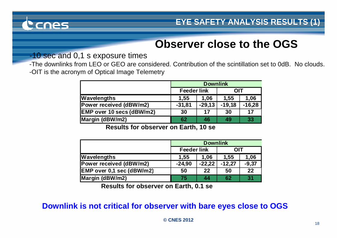
EYE SAFETY ANALYSIS RESULTS (1)
Wavelengths 1,55 1,06 1,55 1,06Power received (dBW/m2) -31,81 -29,13 -19,18 -16,28EMP over 10 secs (dBW/m2) 30 17 30 17Margin (dBW/m2) 62 46 49 33
DownlinkFeeder link OIT
Wavelengths 1,55 1,06 1,55 1,06Power received (dBW/m2) -24,90 -22,22 -12,27 -9,37EMP over 0,1 sec (dBW/m2) 50 22 50 22Margin (dBW/m2) 75 44 62 31
DownlinkFeeder link OIT
Observer close to the OGS-10 sec and 0,1 s exposure times-The downlinks from LEO or GEO are considered. Contribution of the scintillation set to 0dB. No clouds.-OIT is the acronym of Optical Image Telemetry
Results for observer on Earth, 0.1 se
Results for observer on Earth, 10 se
Downlink is not critical for observer with bare eyes clo se to OGS
19© CNES 2012
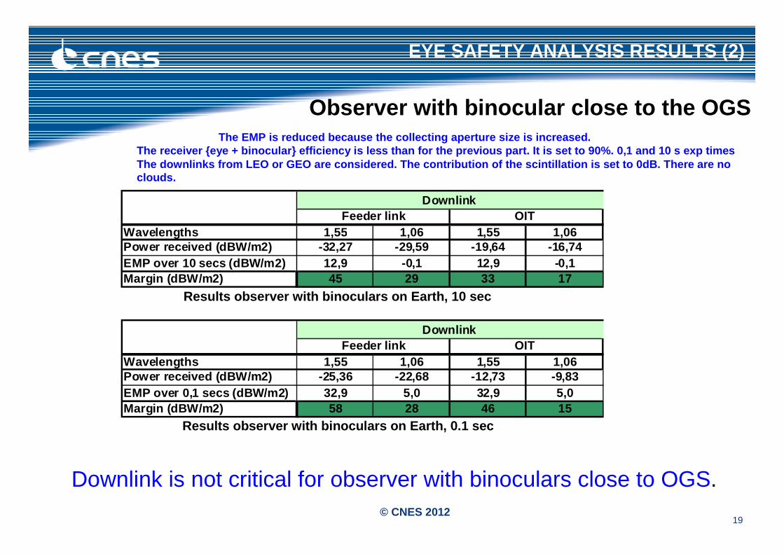
EYE SAFETY ANALYSIS RESULTS (2)
Wavelengths 1,55 1,06 1,55 1,06Power received (dBW/m2) -32,27 -29,59 -19,64 -16,74EMP over 10 secs (dBW/m2) 12,9 -0,1 12,9 -0,1Margin (dBW/m2) 45 29 33 17
DownlinkFeeder link OIT
Wavelengths 1,55 1,06 1,55 1,06Power received (dBW/m2) -25,36 -22,68 -12,73 -9,83EMP over 0,1 secs (dBW/m2) 32,9 5,0 32,9 5,0Margin (dBW/m2) 58 28 46 15
DownlinkFeeder link OIT
The EMP is reduced because the collecting aperture size is increased. The receiver {eye + binocular} efficiency is less t han for the previous part. It is set to 90%. 0,1 an d 10 s exp timesThe downlinks from LEO or GEO are considered. The c ontribution of the scintillation is set to 0dB. The re are no clouds.
Results observer with binoculars on Earth, 10 sec
Results observer with binoculars on Earth, 0.1 sec
Downlink is not critical for observer with binoculars close to OGS.
Observer with binocular close to the OGS
20© CNES 2012
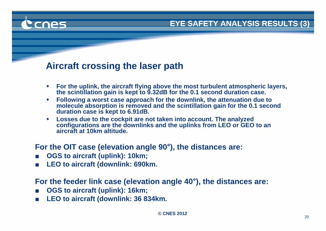
Aircraft crossing the laser path
� For the uplink, the aircraft flying above the most turbulent atmospheric layers, the scintillation gain is kept to 9.32dB for the 0. 1 second duration case.
� Following a worst case approach for the downlink, t he attenuation due to molecule absorption is removed and the scintillatio n gain for the 0.1 second duration case is kept to 6.91dB.
� Losses due to the cockpit are not taken into accoun t. The analyzed configurations are the downlinks and the uplinks fr om LEO or GEO to an aircraft at 10km altitude.
For the OIT case (elevation angle 90 °°°°), the distances are:■ OGS to aircraft (uplink): 10km;■ LEO to aircraft (downlink: 690km.
For the feeder link case (elevation angle 40 °°°°), the distances are:■ OGS to aircraft (uplink): 16km;■ LEO to aircraft (downlink: 36 834km.
EYE SAFETY ANALYSIS RESULTS (3)
21© CNES 2012
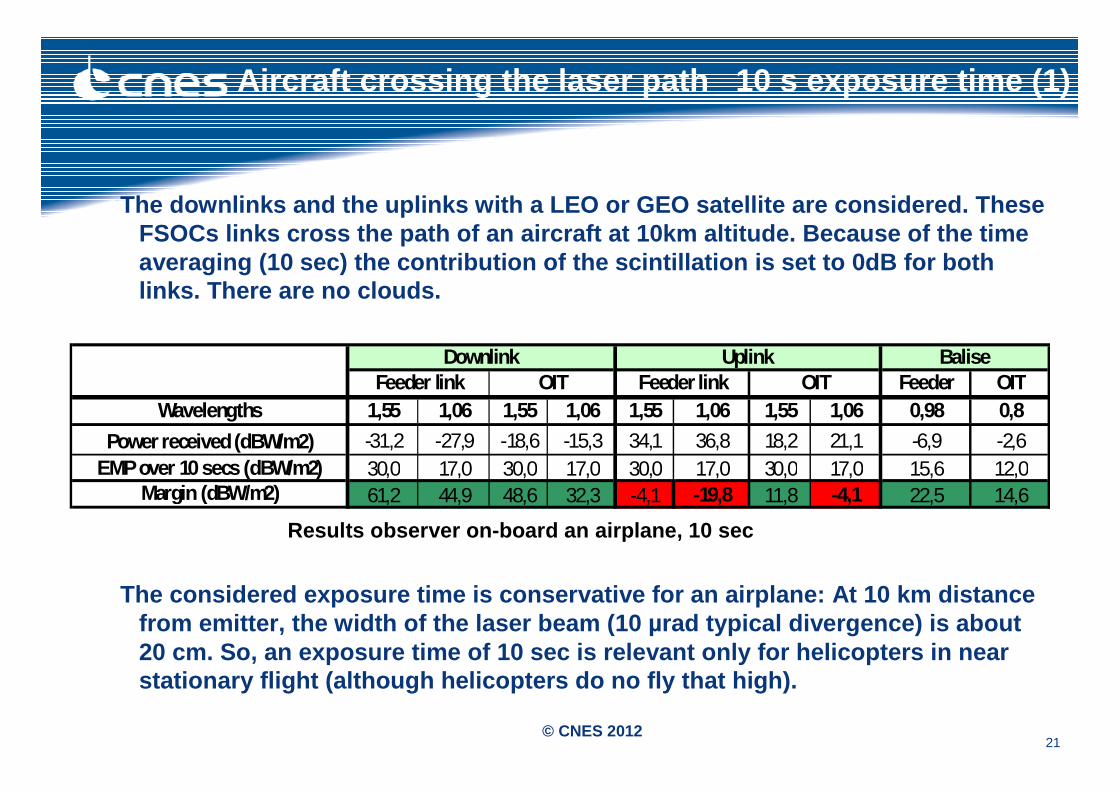
Aircraft crossing the laser path 10 s exposure ti me (1)
The downlinks and the uplinks with a LEO or GEO sat ellite are considered. These FSOCs links cross the path of an aircraft at 10km al titude. Because of the time averaging (10 sec) the contribution of the scintill ation is set to 0dB for both links. There are no clouds.
Results observer on-board an airplane, 10 sec
The considered exposure time is conservative for an airplane: At 10 km distance from emitter, the width of the laser beam (10 µrad t ypical divergence) is about 20 cm. So, an exposure time of 10 sec is relevant o nly for helicopters in near stationary flight (although helicopters do no fly t hat high).
Feeder OITWavelengths 1,55 1,06 1,55 1,06 1,55 1,06 1,55 1,06 0,98 0,8
Power received (dBW/m2) -31,2 -27,9 -18,6 -15,3 34,1 36,8 18,2 21,1 -6,9 -2,6EMP over 10 secs (dBW/m2) 30,0 17,0 30,0 17,0 30,0 17,0 30,0 17,0 15,6 12,0
Margin (dBW/m2) 61,2 44,9 48,6 32,3 -4,1 -19,8 11,8 -4,1 22,5 14,6
BaliseDownlink UplinkFeeder link OIT Feeder link OIT
22© CNES 2012
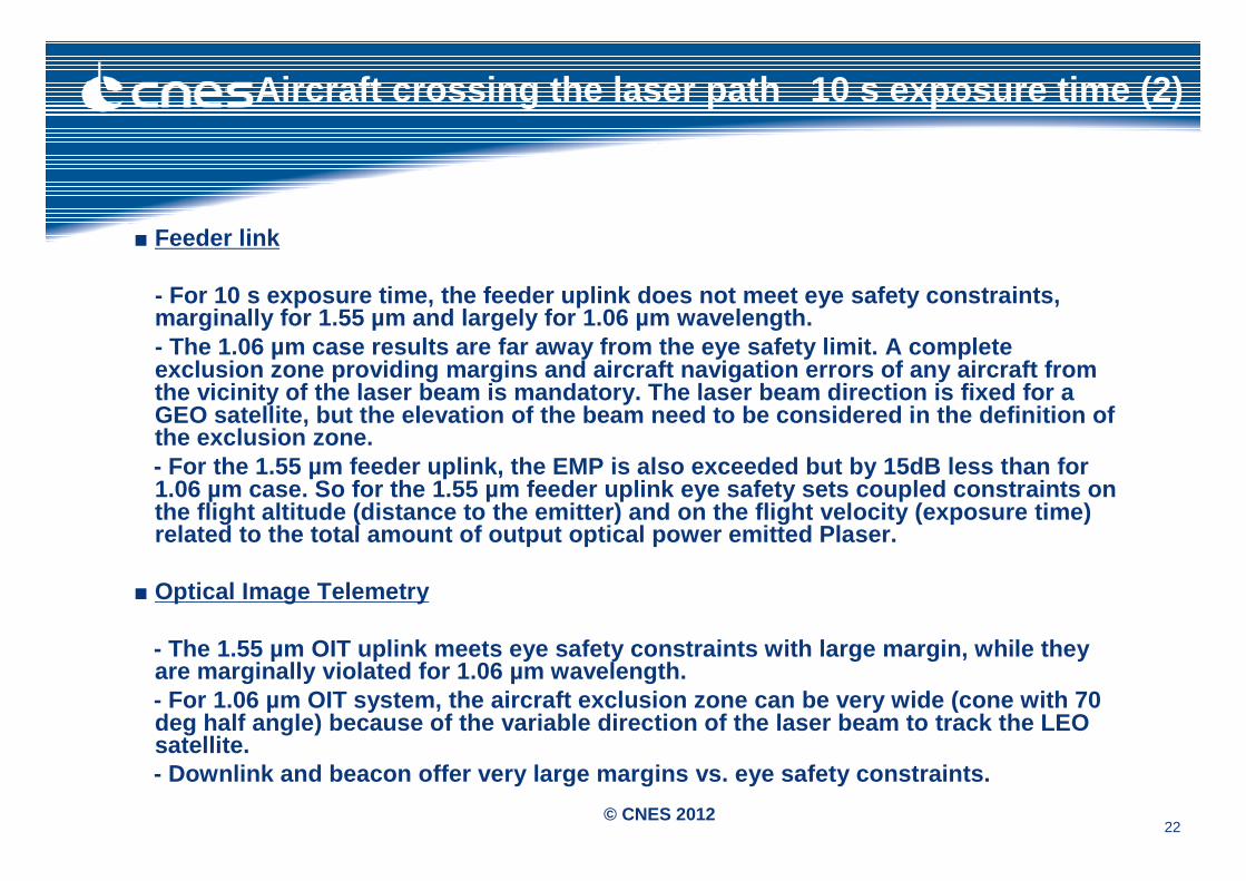
Aircraft crossing the laser path 10 s exposure ti me (2)
■ Feeder link
- For 10 s exposure time, the feeder uplink does not meet eye safety constraints, marginally for 1.55 µm and largely for 1.06 µm wave length. - The 1.06 µm case results are far away from the eye safety limit. A complete exclusion zone providing margins and aircraft navig ation errors of any aircraft from the vicinity of the laser beam is mandatory. The la ser beam direction is fixed for a GEO satellite, but the elevation of the beam need t o be considered in the definition of the exclusion zone.- For the 1.55 µm feeder uplink, the EMP is also exc eeded but by 15dB less than for 1.06 µm case. So for the 1.55 µm feeder uplink eye safety sets coupled constraints on the flight altitude (distance to the emitter) and o n the flight velocity (exposure time) related to the total amount of output optical power emitted Plaser.
■ Optical Image Telemetry
- The 1.55 µm OIT uplink meets eye safety constraint s with large margin, while they are marginally violated for 1.06 µm wavelength. - For 1.06 µm OIT system, the aircraft exclusion zon e can be very wide (cone with 70 deg half angle) because of the variable direction o f the laser beam to track the LEO satellite.- Downlink and beacon offer very large margins vs. e ye safety constraints.
23© CNES 2012
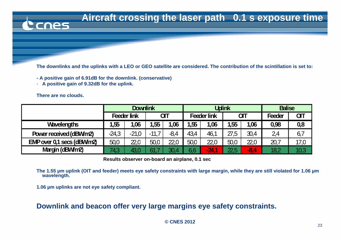
The downlinks and the uplinks with a LEO or GEO sat ellite are considered. The contribution of the scin tillation is set to:
- A positive gain of 6.91dB for the downlink. (conse rvative)- A positive gain of 9.32dB for the uplink.
There are no clouds.
Results observer on-board an airplane, 0.1 sec
The 1.55 µm uplink (OIT and feeder) meets eye safet y constraints with large margin, while they are sti ll violated for 1.06 µm wavelength.
1.06 µm uplinks are not eye safety compliant.
Downlink and beacon offer very large margins eye sa fety constraints.
Aircraft crossing the laser path 0.1 s exposure t ime
Feeder OITWavelengths 1,55 1,06 1,55 1,06 1,55 1,06 1,55 1,06 0,98 0,8
Power received (dBW/m2) -24,3 -21,0 -11,7 -8,4 43,4 46,1 27,5 30,4 2,4 6,7EMP over 0,1 secs (dBW/m2) 50,0 22,0 50,0 22,0 50,0 22,0 50,0 22,0 20,7 17,0
Margin (dBW/m2) 74,3 43,0 61,7 30,4 6,6 -24,1 22,5 -8,4 18,2 10,3
BaliseDownlink UplinkFeeder link OIT Feeder link OIT
24© CNES 2012
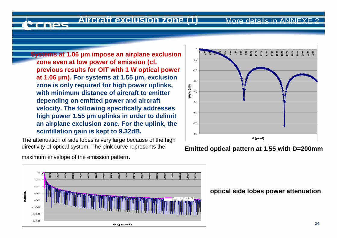
Aircraft exclusion zone (1)
Systems at 1.06 µm impose an airplane exclusion zone even at low power of emission (cf. previous results for OIT with 1 W optical power at 1.06 µm). For systems at 1.55 µm, exclusion zone is only required for high power uplinks, with minimum distance of aircraft to emitter depending on emitted power and aircraft velocity. The following specifically addresses high power 1.55 µm uplinks in order to delimit an airplane exclusion zone. For the uplink, the scintillation gain is kept to 9.32dB. -80
-70
-60
-50
-40
-30
-20
-10
0
0
1,9
2,9
3,9
4,9
5,9
6,9
7,9
8,9
9,9
10,9
11,9
12,9
13,9
14,9
15,9
16,9
17,9
18,9
19,9
20,9
21,9
22,9
θ (µrad)
I(θ)/Io
(dB
)
Emitted optical pattern at 1.55 with D=200mmThe attenuation of side lobes is very large because of the high directivity of optical system. The pink curve represents the
maximum envelope of the emission pattern.
-140
-120
-100
-80
-60
-40
-20
0
θ
66,8
132,8
198,8
264,8
330,8
396,8
462,8
528,8
594,8
660,8
726,8
792,8
858,8
924,8
990,8
1056,8
1122,8
1188,8
1254,8
1320,8
θ (µrad)
I(θ)/Io (dB)
Discrepancy (dB)
I(θ)/Io (dB)
optical side lobes power attenuation
More details in ANNEXE 2
25© CNES 2012
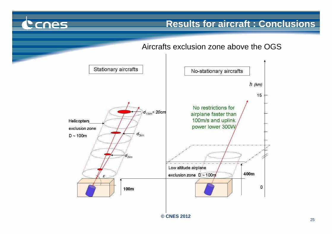
Results for aircraft : Conclusions
Aircrafts exclusion zone above the OGS
26© CNES 2012
Astronaut with telescope on the laser trajectory (1 )
■The Astronaut on-board a LEO vehicle at 400km altit ude is looking in all directions with a 500mm telescope. The EMP is reduc ed because the collecting aperture size increases. The receiver {e ye + telescope} efficiency is set to 95%. The distances are:
~35000 km for GEO-astronaut (downlink);300 km for LEO-spationaute (downlink);400 km for ground-to-astronaut (uplinks for the GEO and the LEO satellites),
consistent with Space Station orbit
■The different uplinks and the downlinks are conside red.
For the downlink:- The scintillation gain for the 0.1 second duration case is removed because
the spationaute is at 400km altitude. - The attenuation due to molecule absorption is remo ved because the aircraft
is located above the troposphere.
27© CNES 2012
Astronaut with telescope on the laser trajectory (2 )
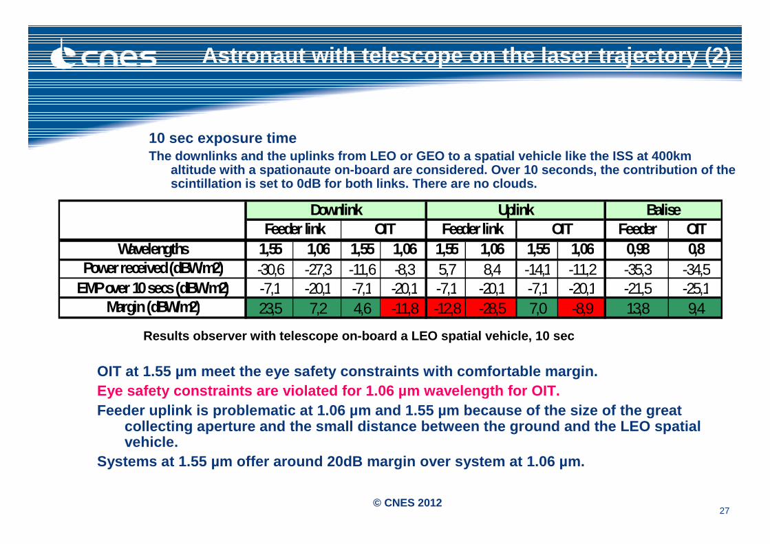
10 sec exposure timeThe downlinks and the uplinks from LEO or GEO to a spatial vehicle like the ISS at 400km
altitude with a spationaute on-board are considered. Over 10 seconds, the contribution of the scintillation is set to 0dB for both links. There a re no clouds.
Results observer with telescope on-board a LEO spat ial vehicle, 10 sec
OIT at 1.55 µm meet the eye safety constraints with comfortable margin. Eye safety constraints are violated for 1.06 µm wav elength for OIT.Feeder uplink is problematic at 1.06 µm and 1.55 µm because of the size of the great
collecting aperture and the small distance between the ground and the LEO spatial vehicle.
Systems at 1.55 µm offer around 20dB margin over sy stem at 1.06 µm.
Feeder OITWavelengths 1,55 1,06 1,55 1,06 1,55 1,06 1,55 1,06 0,98 0,8
Power received (dBW/m2) -30,6 -27,3 -11,6 -8,3 5,7 8,4 -14,1 -11,2 -35,3 -34,5EMP over 10 secs (dBW/m2) -7,1 -20,1 -7,1 -20,1 -7,1 -20,1 -7,1 -20,1 -21,5 -25,1
Margin (dBW/m2) 23,5 7,2 4,6 -11,8 -12,8 -28,5 7,0 -8,9 13,8 9,4
Downlink Uplink BaliseFeeder link OIT Feeder link OIT
28© CNES 2012
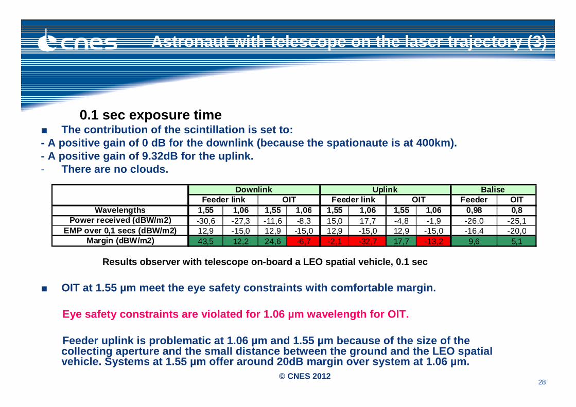
Astronaut with telescope on the laser trajectory (3 )
0.1 sec exposure time■ The contribution of the scintillation is set to:- A positive gain of 0 dB for the downlink (because the spationaute is at 400km). - A positive gain of 9.32dB for the uplink. - There are no clouds.
Results observer with telescope on-board a LEO spat ial vehicle, 0.1 sec
■ OIT at 1.55 µm meet the eye safety constraints with comfortable margin.
Eye safety constraints are violated for 1.06 µm wav elength for OIT.
Feeder uplink is problematic at 1.06 µm and 1.55 µm because of the size of the collecting aperture and the small distance between the ground and the LEO spatial vehicle. Systems at 1.55 µm offer around 20dB margi n over system at 1.06 µm.
Feeder OITWavelengths 1,55 1,06 1,55 1,06 1,55 1,06 1,55 1,06 0,98 0,8
Power received (dBW/m2) -30,6 -27,3 -11,6 -8,3 15,0 17,7 -4,8 -1,9 -26,0 -25,1EMP over 0,1 secs (dBW/m2) 12,9 -15,0 12,9 -15,0 12,9 -15,0 12,9 -15,0 -16,4 -20,0
Margin (dBW/m2) 43,5 12,2 24,6 -6,7 -2,1 -32,7 17,7 -13,2 9,6 5,1
Downlink Uplink BaliseFeeder link OIT Feeder link OIT
29© CNES 2012
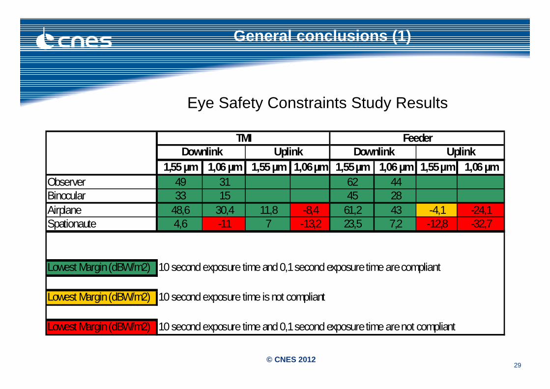
General conclusions (1)
1,55 µm 1,06 µm 1,55 µm 1,06 µm 1,55 µm 1,06 µm 1,55 µm 1, 06 µmObserver 49 31 62 44Binocular 33 15 45 28Airplane 48,6 30,4 11,8 -8,4 61,2 43 -4,1 -24,1Spationaute 4,6 -11 7 -13,2 23,5 7,2 -12,8 -32,7
Lowest Margin (dBW/m2) 10 second exposure time and 0,1 second exposure time are compliant
Lowest Margin (dBW/m2) 10 second exposure time is not compliant
Lowest Margin (dBW/m2) 10 second exposure time and 0,1 second exposure time are not compliant
TMI FeederDownlink Uplink Downlink Uplink
Eye Safety Constraints Study Results
30© CNES 2012
General conclusions (2)
■ Optical Image Telemetry
1.55 μμμμm wavelengths is eye safe with good margins in all c ases.
The 1.06 μμμμm wavelength presents eye safety risk for uplink. If such link is used (not the case in the current OIT link definition), a wide ai rcraft exclusion area around the ground station and a coordination with manned space missions would be needed. Moreover, downlink is also not safe for a astronaut observer. So coordination with manned space missions would also be needed.
■ Feeder link- Downlink is safe for 1.55 μμμμm and 1.06 μμμμm wavelengths- The 1.55 µm uplink marginally violates eye safety c onstraints for stationary aircraftslike helicopters and spationaute cases. For these ca ses, restriction zone with diameter less than 100m along the laser path would be sufficient to protect from eye damage.- The Uplinks at 1.55 µm with optical emitted power up to 300W is eye safe above 400m for airplanes faster than 100 m.s-1.
- The 1.06 µm uplink large violates eye safety const raints, requiring aircraft exclusion area around the ground station and coordination wit h manned space missions.
31© CNES 2012
General conclusions (3)
■ IOT and Feeder applications do not represents risk at 1 .55μμμμm and 1.06μμμμm wavelengths for observer on the earth with or without binocular.
■Systems at 1.55 μμμμm give in average 20dB margin vs. 1.06 μμμμm system for eye safety constraints.
■The 1.55 µm wavelength is therefore clearly prefera ble for links between space and ground. Eye safety sets limited constraints for low altitude airplanes and stationary aircrafts (see Figure Aircrafts exclusion zo ne above the OGS) only in the feeder uplink case, where emitted o ptical power is very large (up to 300 W assumed in the analysis).
32© CNES 2012
ANNEXE 1
33© CNES 2012
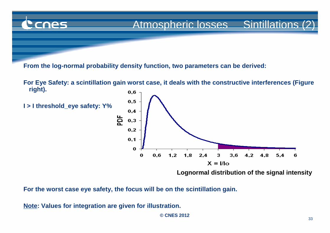
From the log-normal probability density function, t wo parameters can be derived:
For Eye Safety: a scintillation gain worst case, it deals with the constructive interferences (Figure right).
I > I threshold_eye safety: Y%
Lognormal distribution of the signal intensity
For the worst case eye safety, the focus will be on the scintillation gain.
Note : Values for integration are given for illustration .
Atmospheric losses Sintillations (2)
34© CNES 2012
Atmospheric losses Sintillations (3)
The scintillation variance is a bounded random valu e. This means that the signal intensity fluctuation is limited to a saturation level. The limit scintillat ion variance is far higher for the uplink than for the downlink because the turbulence layers are close to the OGS (stratosphere). At saturation level, the following changes have to be noticed:
- No more dependency on the wavelengths,
- For an average turbulence profile, when the entire stratosphere is crossed, the dependency to receiver aperture size disappears[1].
Hence, for the uplink and the downlink, two worst c ase scintillation index σσσσsat_uplink and σσσσsat_downlinkcan be defined for all cases (observer, observer + binocular, observer + telescope because of independency on aperture receiver). This scintillat ion index is valid for the different wavelengths.
Previous ground-to-satellite optical link experimen ts) give homogeneous values for the scintillation i ndices between:
- 0.05 to 1.5 for the uplink;- 0.03 to 0.09 for the downlink.
[1] For a more turbulent atmosphere, the independency o n receiver aperture requires less distance through the stratosphere.
35© CNES 2012
A worst case level of saturation is considered:
σσσσsa_uplink = 4 σσσσsat_downlink = 1
It is prefered to stick to these very conservative v alues, since the one reported in the literature may be linked to specific conditi ons and thus may not be relevant worst cases for the eye safety analysis.
Using the log-normal probability density function o f the normalized signal intensity variation with variance equal to 4 for th e uplink and 1 for the downlink, results in the following worst case ampli fication of the received signal (at 99% probability):
9.3 dB for the uplink; 6.9 dB for th e downlink.
The time scale of the scintillation phenomenon is a lso a key parameter for eye safety analysis. Indeed, as scintillation is quick, the longest time duration (i.e. minimum frequency of the scintillation spectrum) du ring which the optical power received will be stable needs to be determine d. This is analysed for GEO & LEO cases.
Atmospheric losses Sintillations (4)
36© CNES 2012
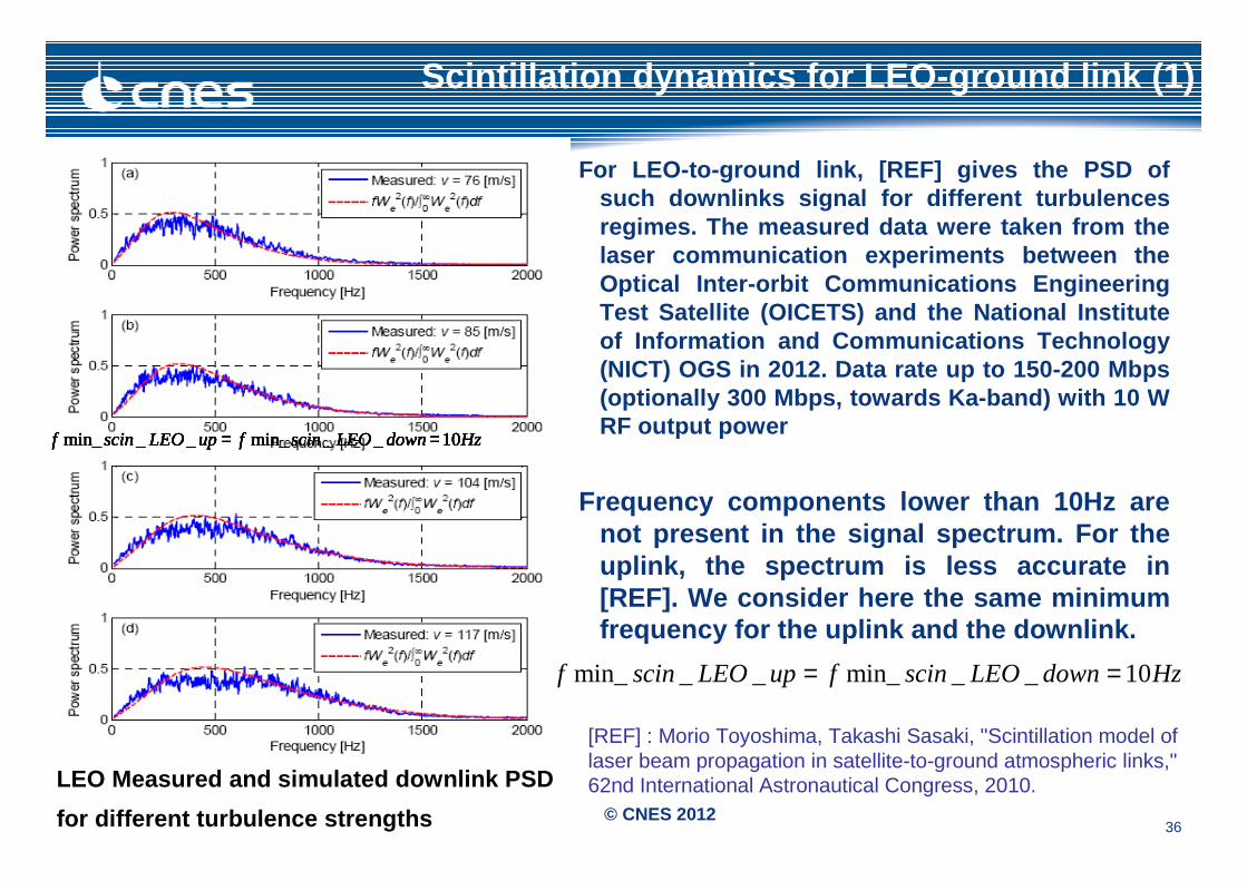
For LEO-to-ground link, [REF] gives the PSD of such downlinks signal for different turbulences regimes. The measured data were taken from the laser communication experiments between the Optical Inter-orbit Communications Engineering Test Satellite (OICETS) and the National Institute of Information and Communications Technology (NICT) OGS in 2012. Data rate up to 150-200 Mbps (optionally 300 Mbps, towards Ka-band) with 10 W RF output power
Frequency components lower than 10Hz are not present in the signal spectrum. For the uplink, the spectrum is less accurate in [REF]. We consider here the same minimum frequency for the uplink and the downlink.
Scintillation dynamics for LEO-ground link (1)
LEO Measured and simulated downlink PSD
for different turbulence strengths
HzdownLEOscinfupLEOscinf 10__min___min_ == HzdownLEOscinfupLEOscinf 10__min___min_ == HzdownLEOscinfupLEOscinf 10__min___min_ == HzdownLEOscinfupLEOscinf 10__min___min_ == HzdownLEOscinfupLEOscinf 10__min___min_ ==
HzdownLEOscinfupLEOscinf 10__min___min_ ==
[REF] : Morio Toyoshima, Takashi Sasaki, "Scintillation model of laser beam propagation in satellite-to-ground atmospheric links," 62nd International Astronautical Congress, 2010.
37© CNES 2012
ANNEXE 2
38© CNES 2012
Aircraft exclusion zone (2)
EMP: EMP(T, h) with T (duration of exposure) dependant on h [100m;30km] and Vairplane [5;500 m.s-1]
Flight speeds between 0m.s-1 to 500m.s-1 are considered. Helicopters go from stationary flight to 100 m.s-1 at altitude between 0 to 10km. Airplanes flight at 10km altitude at an average speed of 250 m.s-1.
As 90% of the total amount of optical power is concentrated in the main lobe (20*10-6 rad divergence), the time duration of exposure to the laser is computed depending on the altitude (h) and the speed (V) of the fighting vehicle with the following formula:
Exposure time varies from 4x10⁻⁶ to 3.6x10⁻² seconds when altitude varies from 100m to 30km and speed from 5 m.s-1 to 500 m.s-1.Then, from Table 2.1-1 we get the related EMP(T,h).
][*10*20 6
sV
hT
airplane
−
=
39© CNES 2012
Aircraft exclusion zone (3)
Received optical power: Precv(h,Plaser) with h [100m;30km] and Plaser [0.1W; 300W]The received optical power Precv(h,Plaser) at a given altitude h between (100m and 30km) is computed with a scintillation gain of 9.32dB and Plaser between 0.1W and 300W.
Depointing angle and exclusion zone: The exclusion zone is defined by:The minimum distance from the emitter (h) where the difference between the EMP(T,h) and the received optical power Precv is positive. The angular offset from the emission direction where the EMP is lower or equal to the power in the emission pattern. The offset angle q is computed from the pink curve in Figure slide 29 that smoothes the pattern of radiation by keeping only the maximums. This offset angle multiplied by the distance h gives the radius of the conical exclusion zone for the distance h.
][*),( mhhTdh θ=
40© CNES 2012
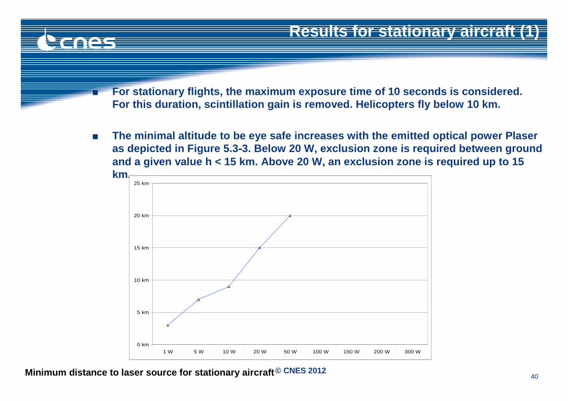
Results for stationary aircraft (1)
■ For stationary flights, the maximum exposure time o f 10 seconds is considered. For this duration, scintillation gain is removed. H elicopters fly below 10 km.
■ The minimal altitude to be eye safe increases with the emitted optical power Plaseras depicted in Figure 5.3----3. Below 20 W, exclusion zone is required between g round and a given value h < 15 km. Above 20 W, an exclusion zone is required up to 15 km.
0 km
5 km
10 km
15 km
20 km
25 km
1 W 5 W 10 W 20 W 50 W 100 W 150 W 200 W 300 W
Minimum distance to laser source for stationary air craft
41© CNES 2012
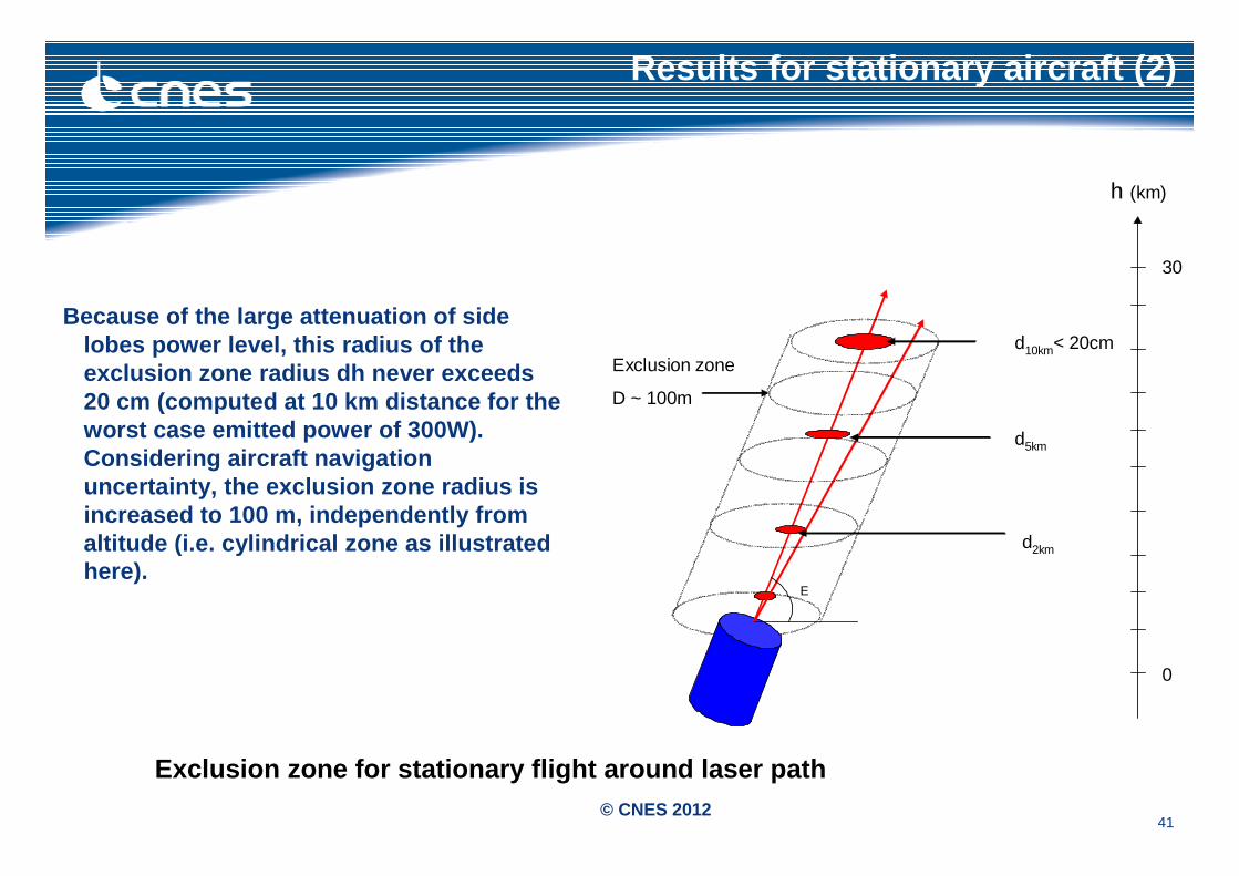
Results for stationary aircraft (2)
Because of the large attenuation of side lobes power level, this radius of the exclusion zone radius dh never exceeds 20 cm (computed at 10 km distance for the worst case emitted power of 300W). Considering aircraft navigation uncertainty, the exclusion zone radius is increased to 100 m, independently from altitude (i.e. cylindrical zone as illustrated here).
h (km)
d10km< 20cm
E
d5km
Exclusion zone
D ~ 100m
d2km
30
0
Exclusion zone for stationary flight around laser p ath
42© CNES 2012
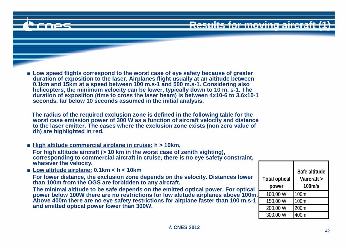
Results for moving aircraft (1)
■ Low speed flights correspond to the worst case of e ye safety because of greater duration of exposition to the laser. Airplanes flig ht usually at an altitude between 0.1km and 15km at a speed between 100 m.s-1 and 500 m.s-1. Considering also helicopters, the minimum velocity can be lower, typ ically down to 10 m. s-1. The duration of exposition (time to cross the laser bea m) is between 4x10⁻⁶ to 3.6x10⁻¹ seconds, far below 10 seconds assumed in the initia l analysis.
The radius of the required exclusion zone is define d in the following table for the worst case emission power of 300 W as a function of aircraft velocity and distance to the laser emitter. The cases where the exclusion zone exists (non zero value of dh) are highlighted in red.
■ High altitude commercial airplane in cruise: h > 10km, For high altitude aircraft (> 10 km in the worst ca se of zenith sighting), corresponding to commercial aircraft in cruise, the re is no eye safety constraint, whatever the velocity.
■ Low altitude airplane: 0.1km < h < 10kmFor lower distance, the exclusion zone depends on t he velocity. Distances lower than 100m from the OGS are forbidden to any aircraf t.The minimal altitude to be safe depends on the emit ted optical power. For optical power below 100W there are no restrictions for low altitude airplanes above 100m. Above 400m there are no eye safety restrictions for airplane faster than 100 m.s-1 and emitted optical power lower than 300W.
Total opticalpower
Safe altitudeVaircraft >
100m/s100,00 W 100m150,00 W 100m200,00 W 200m300,00 W 400m
43© CNES 2012
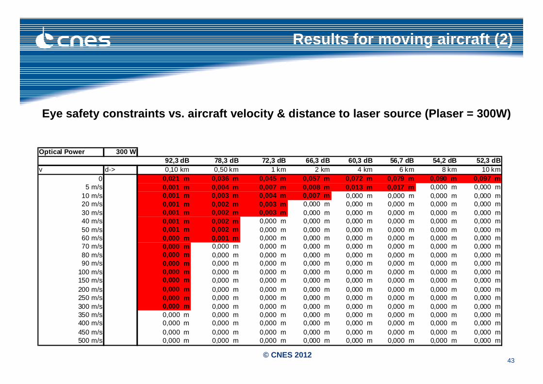
Optical Power 300 W92,3 dB 78,3 dB 72,3 dB 66,3 dB 60,3 dB 56,7 dB 54,2 dB 52,3 dB
v d-> 0,10 km 0,50 km 1 km 2 km 4 km 6 km 8 km 10 km0 0,021 m 0,036 m 0,045 m 0,057 m 0,072 m 0,079 m 0,090 m 0,097 m
5 m/s 0,001 m 0,004 m 0,007 m 0,008 m 0,013 m 0,017 m 0,000 m 0,000 m10 m/s 0,001 m 0,003 m 0,004 m 0,007 m 0,000 m 0,000 m 0,000 m 0,000 m20 m/s 0,001 m 0,002 m 0,003 m 0,000 m 0,000 m 0,000 m 0,000 m 0,000 m30 m/s 0,001 m 0,002 m 0,003 m 0,000 m 0,000 m 0,000 m 0,000 m 0,000 m40 m/s 0,001 m 0,002 m 0,000 m 0,000 m 0,000 m 0,000 m 0,000 m 0,000 m50 m/s 0,001 m 0,002 m 0,000 m 0,000 m 0,000 m 0,000 m 0,000 m 0,000 m60 m/s 0,000 m 0,001 m 0,000 m 0,000 m 0,000 m 0,000 m 0,000 m 0,000 m70 m/s 0,000 m 0,000 m 0,000 m 0,000 m 0,000 m 0,000 m 0,000 m 0,000 m80 m/s 0,000 m 0,000 m 0,000 m 0,000 m 0,000 m 0,000 m 0,000 m 0,000 m90 m/s 0,000 m 0,000 m 0,000 m 0,000 m 0,000 m 0,000 m 0,000 m 0,000 m
100 m/s 0,000 m 0,000 m 0,000 m 0,000 m 0,000 m 0,000 m 0,000 m 0,000 m150 m/s 0,000 m 0,000 m 0,000 m 0,000 m 0,000 m 0,000 m 0,000 m 0,000 m200 m/s 0,000 m 0,000 m 0,000 m 0,000 m 0,000 m 0,000 m 0,000 m 0,000 m250 m/s 0,000 m 0,000 m 0,000 m 0,000 m 0,000 m 0,000 m 0,000 m 0,000 m300 m/s 0,000 m 0,000 m 0,000 m 0,000 m 0,000 m 0,000 m 0,000 m 0,000 m350 m/s 0,000 m 0,000 m 0,000 m 0,000 m 0,000 m 0,000 m 0,000 m 0,000 m400 m/s 0,000 m 0,000 m 0,000 m 0,000 m 0,000 m 0,000 m 0,000 m 0,000 m450 m/s 0,000 m 0,000 m 0,000 m 0,000 m 0,000 m 0,000 m 0,000 m 0,000 m500 m/s 0,000 m 0,000 m 0,000 m 0,000 m 0,000 m 0,000 m 0,000 m 0,000 m
Eye safety constraints vs. aircraft velocity & dist ance to laser source (Plaser = 300W)
Results for moving aircraft (2)


![ars.els-cdn.com · Web viewFigure S2 Normalized enzyme catalysis reaction rates versus time. In the simulations, [H 2 O 2] 0 = 117.6 μM, [] 0 = 0.9 ng/ml, [] 0 = 20 μM, K m = 1.55](https://static.fdocuments.us/doc/165x107/5fc02014ef31c235a86bc4b1/arsels-cdncom-web-view-figure-s2-normalized-enzyme-catalysis-reaction-rates-versus.jpg)