PDF (1.55 MB) - IOPscience
8
Journal of Physics: Conference Series OPEN ACCESS Turbulent boundary-layer control with spanwise travelling waves To cite this article: Richard D Whalley and Kwing-So Choi 2011 J. Phys.: Conf. Ser. 318 022039 View the article online for updates and enhancements. You may also like Mechanism of controlling turbulent channel flow with the effect of spanwise Lorentz force distribution Yang Han, , Hui Zhang et al. - Effect of plasma actuator control parameters on a transitional flow Arnob Das Gupta and Subrata Roy - Flow separation on flapping and rotating profiles with spanwise gradients J G Wong, B P laBastide and D E Rival - Recent citations Recent developments in DBD plasma flow control Jin-Jun Wang et al - This content was downloaded from IP address 34.146.204.4 on 24/11/2021 at 14:26
Transcript of PDF (1.55 MB) - IOPscience

Journal of Physics Conference Series
OPEN ACCESS
Turbulent boundary-layer control with spanwisetravelling wavesTo cite this article Richard D Whalley and Kwing-So Choi 2011 J Phys Conf Ser 318 022039
View the article online for updates and enhancements
You may also likeMechanism of controlling turbulent channelflow with the effect of spanwise Lorentzforce distributionYang Han Hui Zhang et al
-
Effect of plasma actuator controlparameters on a transitional flowArnob Das Gupta and Subrata Roy
-
Flow separation on flapping and rotatingprofiles with spanwise gradientsJ G Wong B P laBastide and D E Rival
-
Recent citationsRecent developments in DBD plasma flowcontrolJin-Jun Wang et al
-
This content was downloaded from IP address 341462044 on 24112021 at 1426
Turbulent boundary-layer control with spanwisetravelling waves
Richard D Whalley1 and Kwing-So Choi11 Faculty of Engineering University of Nottingham Nottingham NG7 2RD UK
E-mail RichardWhalleynottinghamacuk
E-mail Kwing-SoChoinottinghamacuk
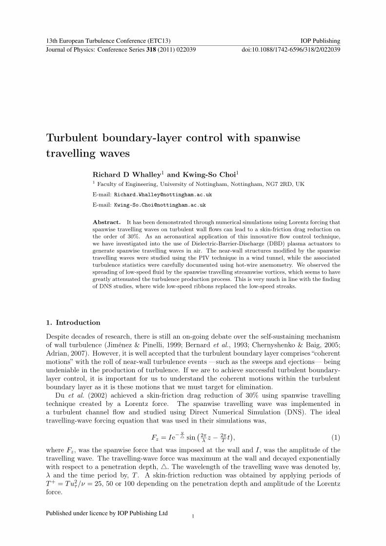
Abstract It has been demonstrated through numerical simulations using Lorentz forcing thatspanwise travelling waves on turbulent wall flows can lead to a skin-friction drag reduction onthe order of 30 As an aeronautical application of this innovative flow control techniquewe have investigated into the use of Dielectric-Barrier-Discharge (DBD) plasma actuators togenerate spanwise travelling waves in air The near-wall structures modified by the spanwisetravelling waves were studied using the PIV technique in a wind tunnel while the associatedturbulence statistics were carefully documented using hot-wire anemometry We observed thespreading of low-speed fluid by the spanwise travelling streamwise vortices which seems to havegreatly attenuated the turbulence production process This is very much in line with the findingof DNS studies where wide low-speed ribbons replaced the low-speed streaks
1 Introduction
Despite decades of research there is still an on-going debate over the self-sustaining mechanismof wall turbulence (Jimeacutenez amp Pinelli 1999 Bernard et al 1993 Chernyshenko amp Baig 2005Adrian 2007) However it is well accepted that the turbulent boundary layer comprises ldquocoherentmotionsrdquo with the roll of near-wall turbulence events mdashsuch as the sweeps and ejectionsmdash beingundeniable in the production of turbulence If we are to achieve successful turbulent boundary-layer control it is important for us to understand the coherent motions within the turbulentboundary layer as it is these motions that we must target for elimination
Du et al (2002) achieved a skin-friction drag reduction of 30 using spanwise travellingtechnique created by a Lorentz force The spanwise travelling wave was implemented ina turbulent channel flow and studied using Direct Numerical Simulation (DNS) The idealtravelling-wave forcing equation that was used in their simulations was
Fz = Ieminusy4 sin
(2πλ z minus
2πT t
) (1)
where Fz was the spanwise force that was imposed at the wall and I was the amplitude of thetravelling wave The travelling-wave force was maximum at the wall and decayed exponentiallywith respect to a penetration depth 4 The wavelength of the travelling wave was denoted byλ and the time period by T A skin-friction reduction was obtained by applying periods ofT+ = Tu2τν = 25 50 or 100 depending on the penetration depth and amplitude of the Lorentzforce
13th European Turbulence Conference (ETC13) IOP PublishingJournal of Physics Conference Series 318 (2011) 022039 doi1010881742-65963182022039
Published under licence by IOP Publishing Ltd 1
a)Mylar Dielectric
Lower Electrode
Jet Flow
Plasma
Upper Electrode
x x
Sinusoidal Waveform
b)x x6 mm
25 mm17
microm
250
microm
Figure 1 Schematic representation of a DBD plasma actuator used in the present study a) cross-section and b) dimensions
The Lorentz force is limited to a conducting medium such as sea water Therefore to makethis innovative flow control technique applicable to air flows we have investigated into the useof creating spanwise travelling waves with Dielectric Barrier Discharge (DBD) plasma DBDplasma actuators consist of an upper and lower electrode separated by a thin dielectric materialfigure 1a On application of several kilovolts of AC power at kilohertz frequency between theseelectrodes local ionization takes place around the upper electrode and couples momentum to theflow (Enloe et al 2004) It has been shown that on initiation of DBD plasma in quiescent air astarting vortex (Whalley amp Choi 2010a) is generated This vortex rolls up and moves along andaway from the surface with continual plasma forcing leading the formation of a laminar wall jet
In this paper we present an experimental study using hot-wire anemometry and ParticleImage Velocimetry (PIV) of spanwise travelling waves generated in air with DBD plasma forskin-friction reduction inside the turbulent boundary layer As DBD plasma is a surface basedtechnique it makes an ideal candidate for turbulent boundary-layer control with spanwisetravelling-wave excitation
2 Experimental Set-up
Turbulent boundary-layer measurements were conducted using a low-speed closed-loop windtunnel The wind tunnel had a cross section of 508 x 508 mm2The turbulent boundary layerwas developed over a 3 m long flat plate which was fabricated from 20 mm thick polished MDFand had a super-elliptic leading edge and a trailing-edge flap The flat plate was positioned inthe upper section of the wind tunnel with a turbulent trip placed 100 mm downstream from theleading edge Measurements were taken a further 23 m downstream from the trip where theturbulent boundary layer was fully developed The free-stream velocity was set at Uinfin = 17 mswith turbulence intensity of 024 The turbulent boundary-layer thickness was δ = 90 mmand the viscous sublayer was 1 mm The Reynolds number based on the friction velocity wasReτ = 435 the Reynolds number based on the momentum thickness was Reθ = 1024 and theshape factor was H = 146 The pressure gradient across the test section was nearly zero
The plasma actuator sheets used in the spanwise travelling wave experiments werephotochemically etched from a copper-clad Mylar sheet (250 microm thick dielectric constantε = 31) Each plasma actuator sheet consisted of 24 copper electrodes which were poweredby a set of high voltage sinusoidal RF inputs The upper and lower electrodes were 25 mm and6 mm (z+ = zuτν = 13 and 30) in width respectively and protruded by 17 microm (y+ = 009) from
13th European Turbulence Conference (ETC13) IOP PublishingJournal of Physics Conference Series 318 (2011) 022039 doi1010881742-65963182022039
2
a)
x
x
b)
x
x
Figure 2 Schematic representation of 4-phase spanwise travelling waves generated with plasmaa) Unidirectional forcing and b) bidirectional forcing
the wall (see figure 1b) Each actuator had an active length of 338 mm (x+ = 1690) The plasmaactuator sheets were used to generate 4-phase spanwise travelling waves with two different forcingconfigurations over 3 wavelengths of l = 100 mm
(l+ = 500
) Unidirectional forcing actuated in
one direction per phase and bidirectional forcing actuated in two opposing directions per phasewith electrodes separated by 56 mm (s+ = 280) Figure 2ab shows schematic representationsof the uni and bidirectional forcing configurations respectively For the data presented in thispaper the sinusoidal voltage input to the plasma power supplies was fixed at E = 7 kVp-p at afrequency of f = 25 kHz and applied with a forcing period of T = 208 ms (T+ = 82) requiringup to 12 plasma power supplies
Flow diagnostics were made by constant temperature hot-wire anemometry and PIV Thehot-wire measurements of the streamwise velocity were taken with Dantec 55P15 probes Oneprobe was used to obtain the boundary-layer profile whilst another probe was kept stationary inthe free stream of the wind tunnel to monitor the free-stream velocity Each probe was operatedwith an overheat ratio of 18 and calibrated in-situ The ambient temperature drift duringexperiments was monitored using a LM35 Precision Temperature Senor and the hot-wire datawas compensated accordingly
The velocity fields of the x-z and z-y planes in the turbulent boundary layer were obtainedwith a time-resolved PIV system from TSI The 2D PIV in the x-z plane were performed 1 mm(y+ = 5) from the wall within the viscous sublayer These measurements had a field of view of100 mm x 100 mm (x+ = 500 z+ = 500) and were positioned such that (x+ z+) = (250 250)was the centre of the travelling-wave actuator sheet The measurements in the z-y plane ofthe turbulent boundary layer were performed using stereoscopic PIV The stereoscopic PIVdata had a field of view of 100 mm x 40 mm (z+ = 500 y+ = 200) and positioned such that(z+ y+) = (250 0) was the centre of the travelling-wave actuator sheet with y+ = 0 being thelocation of the wall With respect to the x-z plane measurements the z-y plane measurements
13th European Turbulence Conference (ETC13) IOP PublishingJournal of Physics Conference Series 318 (2011) 022039 doi1010881742-65963182022039
3
x+
z+
U+
0 100 200 300 400 5000
100
200
300
400
500
x x0
25
x+
z+
ltU
+gt
0 100 200 300 400 5000
100
200
300
400
500
x x0
25
x+
z+
ltU
+gt
0 100 200 300 400 5000
100
200
300
400
500
x x0
25
Figure 3 Streamwise velocity measurements in the x-z plane of the turbulent boundary layerat y+ = 5 showing a) canonical data b) uni-directional spanwise travelling-wave data at 1
2T+
and c) bi-directional spanwise travelling-wave data at 34T
+ l+ = 500 T+ = 82 Scaled with
canonical uτ
were taken at x+ = 200 Data processing was performed using INSIGHT 3G software from TSIusing a cross-correlation algorithm to generate vectors over a 32 x 32 pixel interrogation areawith 50 overlap to an accuracy of 3minus 5 (Westerweel 1997)
3 Results and Discussion
The change in near-wall structure of the turbulent boundary layer in the x-z plane at y+ = 5with spanwise travelling waves is shown in figure 3 The boundary-layer flow is in the positivexminusdirection and the spanwise travelling wave is moving in the positive zminusdirection The near-wall streaky structure (no-control) can be seen in figure 3a where the low- and high-speedstreaks can be seen meandering through the flow with characteristic streak spacing of z+ = 100The application of spanwise travelling waves with uni and bidirectional excitations with periodT+ = 82 are shown in figure 3b and figure 3c respectively The spanwise travelling-wave datashown here have been phase-averaged over 51 forcing periods Unidirectional forcing figure 3bhas plasma forcing at z+ = 225 (with actuators on the side of each image to show the location ofplasma forcing) A wide ribbon of low-speed streamwise velocity is being pushed in the positivespanwise direction 300 lt z+ lt 400 and z+ lt 300 has no clear sign of near-wall streakystructures due to plasma forcing of previous phases Bidirectional forcing is shown in figure 3cwith plasma forcing at z+ = 50 and z+ = 350 Again there is a large change in near-wallstructure as compared to the no-control case figure 3a Here collections of low-speed ribbonsfor z+ lt 50 100 lt z+ lt 300 and 350 lt z+ lt 500 can be seen This is a combination of the low-speed streamwise velocity collected during the current and previous phases of the travelling-waveexcitation
Stereoscopic PIV measurements in the z-y plane of the turbulent boundary layer with spanwisetravelling waves are shown in figure 4 In figure 4 the boundary-layer flow is moving into theplane of the paper and images are taken at a streamwise distance of x+ = 200 in relation withthe x-z plane data Figure 4a shows streamwise vorticity with unidirectional forcing (in the leftcolumn) where a co-rotating streamwise vortex can be seen by the strong negative vorticitywith arrows of Vminus and Wminus components of velocity The streamwise vortex generated duringunidirectional forcing is entraining low-speed streamwise velocity from the near-wall region intothe core of the streamwise vortex and around its periphery figure 4b The streamwise vortex isbeing thrust in the spanwise direction by the activated plasma actuator which produces strongpositive spanwise velocity along the wall figure 4f The positive spanwise velocity extends toa wall-normal distance of y+ = 50 figure 4c and due to induction by the streamwise vortexnegative spanwise velocity is seen above the vortex core 50 lt y+ lt 100 The streamwise vortex
13th European Turbulence Conference (ETC13) IOP PublishingJournal of Physics Conference Series 318 (2011) 022039 doi1010881742-65963182022039
4
y+
ltωxgt
(sminus1)
0
100
200
x xminus200
200
y+
ltωxgt
(sminus1)
0
100
200
x xminus200
200
y+
ltU
+gt
0
100
200
x x0
25
y+
ltU
+gt
0
100
200
x x0
25
y+
ltW
+gt
0
100
200
x xminus10
10
y+
ltW
+gt
0
100
200
x xminus10
10
y+
ltV
+gt
0
100
200
x xminus5
5y+
ltV
+gt
0
100
200
x xminus5
5
x+
ltU
+gt
0
100
200
300
400
500
x x
0
25
x+
ltU
+gt
0
100
200
300
400
500
x x
0
25
x+
ltW
+gt
0
100
200
300
400
500
0 100 200 300 400 500z+
x xminus10
10
x+
ltW
+gt
0
100
200
300
400
500
0 100 200 300 400 500z+
x xminus10
10
Figure 4 Phase-averaged data in the z-y and x-z planes of the turbulent boundary layer withspanwise travelling-wave excitation by plasma with unidirectional forcing at 1
2T+ (left column)
and with bidirectional forcing at 34T
+ (right column) a) Streamwise vorticity (y-z plane)b) streamwise velocity (y-z plane) c) spanwise velocity (y-z plane) d) wall-normal velocity(x-z plane) e) streamwise velocity (x-z plane) and f) spanwise velocity (x-z plane) l
+ = 500T+ = 82 Scaled with canonical uτ
13th European Turbulence Conference (ETC13) IOP PublishingJournal of Physics Conference Series 318 (2011) 022039 doi1010881742-65963182022039
5
100
101
102
1030
5
10
15
20
25
30
y+
U+
No Control Data (Uni)No Control Data (Bi)Travelling Wave (Uni)Travelling Wave (Bi)
U+ = 585log10y+ + 556 Schlichting (1979)
Figure 5 Mean velocity profile in the turbulent boundary layer with spanwise travelling-waveexcitation by plasma l+ = 500 T+ = 82 Scaled with canonical uτ
creates both upwash and downwash figure 4d with the region of downwash coinciding with thelocation of the plasma actuator and a region of high-speed streamwise velocity in the near-wallregion figure 4e The location of the wide ribbon of low-speed fluid figure 4e coincides with thelocation of the streamwise vortex figure 4a Hence the streamwise vortex that is travelling in thespanwise direction is effectively spreading the near-wall streaks into wide ribbons of low-speedfluid
Figure 4a shows streamwise vorticity with bidirectional forcing (in the right column) whereco- and counter-rotating streamwise vortices can be seen by the strong negative and positivevorticity Both co- and counter-rotating vortices are created with bidirectional forcing as theplasma actuators fire in two opposing directions each phase As has been seen with unidirectionalforcing the streamwise vortices generated during bidirectional forcing are entraining low-speedstreamwise velocity from the near-wall region into the streamwise vortex cores and around theirperipheries figure 4b The streamwise vortices are being thrust in both the positive and negativespanwise direction by the activated plasma actuators which produces both strong positive andnegative spanwise velocity along the wall figure 4f that extends to a wall-normal distanceof y+ = 50 figure 4c Again as was found with unidirectional forcing the streamwise vorticesgenerated with bidirectional forcing create spanwise velocity for 50 lt y+ lt 100 due to inductionalong with positive and negative wall-normal velocity figure 4d which coincides with regionsof high-speed streamwise velocity in the near-wall region figure 4e Furthermore the locationof the wide ribbons of low-speed fluid figure 4e coincide with the locations of the streamwisevortices figure 4a
Streamwise velocity profiles which have been phase-averaged over four spanwise locationswith spanwise travelling-wave excitations are shown in figure 5 Both the uni and bidirectionaltravelling waves yield a large reduction in streamwise velocity in the logarithmic region of theturbulent boundary layer of 10 and 20 respectively typically up to a wall-normal distanceof y+ = 200 The reduction in streamwise velocity is due to the upwash of low-speed streamwisevelocity from the viscous sublayer by the streamwise vortices as shown in figure 4b At the sametime the spanwise travelling waves cause an increase in the streamwise velocity in the near-wallregion y+ lt 20 due to the downwash associated with the plasma actuators figure 4d
We have previously demonstrated (Choi et al 2011) that the unidirectional travellingwave creates streamwise vortices in sequence which move as a single vortex engulfing theneighbouring vortices from previous phases The bidirectional travelling wave activates plasma
13th European Turbulence Conference (ETC13) IOP PublishingJournal of Physics Conference Series 318 (2011) 022039 doi1010881742-65963182022039
6
in two opposite directions per phase causing a complex interaction of co- and counter-rotatingstreamwise vortices that lift one another away from the wall to maintain the travelling-waveexcitation (Whalley amp Choi 2010b) Both forcing configurations generate a streamwise vortexas demonstrated in figure 4a that travels in the spanwise direction It is thought that thestreamwise vortex which is travelling in the spanwise direction is spreading the low-speed fluidwithin the viscous sublayer creating wide ribbons of low-speed fluid This result is in linewith DNS studies (Du et al 2002) and it is conjectured that the spanwise travelling waves arestabilising the near-wall streaky structure leading to a reduction in turbulent skin-friction
4 Conclusions
Our results have shown that spanwise travelling waves with uni and bidirectional forcingconfigurations can be implemented in air with DBD plasma inside the turbulent boundary layerThe unidirectional travelling wave creates streamwise vortices in sequence which move as a singlevortex engulfing the neighbouring vortices from previous phases The bidirectional travellingwave activates plasma in two opposite directions per phase causing complex interactions betweenco- and counter-rotating streamwise vortices It has been seen that both forcing configurationsgenerate streamwise vortices that spread the low-speed fluid within the viscous sublayer creatingwide ribbons of low-speed fluid This result is in line with DNS studies (Du et al 2002) and itis conjectured that the spanwise travelling waves implemented with DBD plasma are stabilisingthe sublayer streaks and have the potential to realise large reductions in skin-friction drag
Acknowledgements
This work has been jointly funded by the FP6 framework programmdashAVERT and the Engineeringand Physical Sciences Research Council
References
Adrian R J 2007 Hairpin vortex organization in wall turbulence Physics of Fluids 19 041301Bernard P S Thomas J M amp Handler R A 1993 Vortex dynamics and the productionof Reynolds stress Journal of Fluid Mechanics 253 385ndash419
Chernyshenko S I amp Baig M F 2005 The mechanism of streak formation in near-wallturbulence Journal of Fluid Mechanics 544 99ndash131
Choi K-S Jukes T N amp Whalley R 2011 Turbulent boundary-layer control with plasmaactuators Philosophical Transactions of the Royal Society A 369 1443ndash1458
Du Y Symeonidis Y amp Karniadakis G E 2002 Drag reduction in wall-boundedturbulence via a transverse travelling wave Journal of Fluid Mechanics 457 1ndash34
Enloe C L McLaughlin T E VanDyken R D Kachner K D Jumper E J ampCorke TC 2004 Mechanisms and responses of a single dielectric barrier plasma actuatorPlasma morphology AIAA Journal 42 (3) 589ndash594
Jimeacutenez J amp Pinelli A 1999 The autonomous cycle of near-wall turbulence Journal ofFluid Mechanics 389 335ndash359
Westerweel J 1997 Fundamentals of digital particle image velocimetry Measurement Scienceand Technology 8 1379ndash1392
Whalley R amp Choi K-S 2010a Starting traveling and colliding vortices Dielectric-barrier-discharge plasma in quiescent air Physics of Fluids 22 091105
Whalley R amp Choi K-S 2010b Turbulent boundary layer control with DBD plasma Aspanwise travelling wave In 5th AIAA Flow Control Conference AIAA
13th European Turbulence Conference (ETC13) IOP PublishingJournal of Physics Conference Series 318 (2011) 022039 doi1010881742-65963182022039
7
Turbulent boundary-layer control with spanwisetravelling waves
Richard D Whalley1 and Kwing-So Choi11 Faculty of Engineering University of Nottingham Nottingham NG7 2RD UK
E-mail RichardWhalleynottinghamacuk
E-mail Kwing-SoChoinottinghamacuk
Abstract It has been demonstrated through numerical simulations using Lorentz forcing thatspanwise travelling waves on turbulent wall flows can lead to a skin-friction drag reduction onthe order of 30 As an aeronautical application of this innovative flow control techniquewe have investigated into the use of Dielectric-Barrier-Discharge (DBD) plasma actuators togenerate spanwise travelling waves in air The near-wall structures modified by the spanwisetravelling waves were studied using the PIV technique in a wind tunnel while the associatedturbulence statistics were carefully documented using hot-wire anemometry We observed thespreading of low-speed fluid by the spanwise travelling streamwise vortices which seems to havegreatly attenuated the turbulence production process This is very much in line with the findingof DNS studies where wide low-speed ribbons replaced the low-speed streaks
1 Introduction
Despite decades of research there is still an on-going debate over the self-sustaining mechanismof wall turbulence (Jimeacutenez amp Pinelli 1999 Bernard et al 1993 Chernyshenko amp Baig 2005Adrian 2007) However it is well accepted that the turbulent boundary layer comprises ldquocoherentmotionsrdquo with the roll of near-wall turbulence events mdashsuch as the sweeps and ejectionsmdash beingundeniable in the production of turbulence If we are to achieve successful turbulent boundary-layer control it is important for us to understand the coherent motions within the turbulentboundary layer as it is these motions that we must target for elimination
Du et al (2002) achieved a skin-friction drag reduction of 30 using spanwise travellingtechnique created by a Lorentz force The spanwise travelling wave was implemented ina turbulent channel flow and studied using Direct Numerical Simulation (DNS) The idealtravelling-wave forcing equation that was used in their simulations was
Fz = Ieminusy4 sin
(2πλ z minus
2πT t
) (1)
where Fz was the spanwise force that was imposed at the wall and I was the amplitude of thetravelling wave The travelling-wave force was maximum at the wall and decayed exponentiallywith respect to a penetration depth 4 The wavelength of the travelling wave was denoted byλ and the time period by T A skin-friction reduction was obtained by applying periods ofT+ = Tu2τν = 25 50 or 100 depending on the penetration depth and amplitude of the Lorentzforce
13th European Turbulence Conference (ETC13) IOP PublishingJournal of Physics Conference Series 318 (2011) 022039 doi1010881742-65963182022039
Published under licence by IOP Publishing Ltd 1
a)Mylar Dielectric
Lower Electrode
Jet Flow
Plasma
Upper Electrode
x x
Sinusoidal Waveform
b)x x6 mm
25 mm17
microm
250
microm
Figure 1 Schematic representation of a DBD plasma actuator used in the present study a) cross-section and b) dimensions
The Lorentz force is limited to a conducting medium such as sea water Therefore to makethis innovative flow control technique applicable to air flows we have investigated into the useof creating spanwise travelling waves with Dielectric Barrier Discharge (DBD) plasma DBDplasma actuators consist of an upper and lower electrode separated by a thin dielectric materialfigure 1a On application of several kilovolts of AC power at kilohertz frequency between theseelectrodes local ionization takes place around the upper electrode and couples momentum to theflow (Enloe et al 2004) It has been shown that on initiation of DBD plasma in quiescent air astarting vortex (Whalley amp Choi 2010a) is generated This vortex rolls up and moves along andaway from the surface with continual plasma forcing leading the formation of a laminar wall jet
In this paper we present an experimental study using hot-wire anemometry and ParticleImage Velocimetry (PIV) of spanwise travelling waves generated in air with DBD plasma forskin-friction reduction inside the turbulent boundary layer As DBD plasma is a surface basedtechnique it makes an ideal candidate for turbulent boundary-layer control with spanwisetravelling-wave excitation
2 Experimental Set-up
Turbulent boundary-layer measurements were conducted using a low-speed closed-loop windtunnel The wind tunnel had a cross section of 508 x 508 mm2The turbulent boundary layerwas developed over a 3 m long flat plate which was fabricated from 20 mm thick polished MDFand had a super-elliptic leading edge and a trailing-edge flap The flat plate was positioned inthe upper section of the wind tunnel with a turbulent trip placed 100 mm downstream from theleading edge Measurements were taken a further 23 m downstream from the trip where theturbulent boundary layer was fully developed The free-stream velocity was set at Uinfin = 17 mswith turbulence intensity of 024 The turbulent boundary-layer thickness was δ = 90 mmand the viscous sublayer was 1 mm The Reynolds number based on the friction velocity wasReτ = 435 the Reynolds number based on the momentum thickness was Reθ = 1024 and theshape factor was H = 146 The pressure gradient across the test section was nearly zero
The plasma actuator sheets used in the spanwise travelling wave experiments werephotochemically etched from a copper-clad Mylar sheet (250 microm thick dielectric constantε = 31) Each plasma actuator sheet consisted of 24 copper electrodes which were poweredby a set of high voltage sinusoidal RF inputs The upper and lower electrodes were 25 mm and6 mm (z+ = zuτν = 13 and 30) in width respectively and protruded by 17 microm (y+ = 009) from
13th European Turbulence Conference (ETC13) IOP PublishingJournal of Physics Conference Series 318 (2011) 022039 doi1010881742-65963182022039
2
a)
x
x
b)
x
x
Figure 2 Schematic representation of 4-phase spanwise travelling waves generated with plasmaa) Unidirectional forcing and b) bidirectional forcing
the wall (see figure 1b) Each actuator had an active length of 338 mm (x+ = 1690) The plasmaactuator sheets were used to generate 4-phase spanwise travelling waves with two different forcingconfigurations over 3 wavelengths of l = 100 mm
(l+ = 500
) Unidirectional forcing actuated in
one direction per phase and bidirectional forcing actuated in two opposing directions per phasewith electrodes separated by 56 mm (s+ = 280) Figure 2ab shows schematic representationsof the uni and bidirectional forcing configurations respectively For the data presented in thispaper the sinusoidal voltage input to the plasma power supplies was fixed at E = 7 kVp-p at afrequency of f = 25 kHz and applied with a forcing period of T = 208 ms (T+ = 82) requiringup to 12 plasma power supplies
Flow diagnostics were made by constant temperature hot-wire anemometry and PIV Thehot-wire measurements of the streamwise velocity were taken with Dantec 55P15 probes Oneprobe was used to obtain the boundary-layer profile whilst another probe was kept stationary inthe free stream of the wind tunnel to monitor the free-stream velocity Each probe was operatedwith an overheat ratio of 18 and calibrated in-situ The ambient temperature drift duringexperiments was monitored using a LM35 Precision Temperature Senor and the hot-wire datawas compensated accordingly
The velocity fields of the x-z and z-y planes in the turbulent boundary layer were obtainedwith a time-resolved PIV system from TSI The 2D PIV in the x-z plane were performed 1 mm(y+ = 5) from the wall within the viscous sublayer These measurements had a field of view of100 mm x 100 mm (x+ = 500 z+ = 500) and were positioned such that (x+ z+) = (250 250)was the centre of the travelling-wave actuator sheet The measurements in the z-y plane ofthe turbulent boundary layer were performed using stereoscopic PIV The stereoscopic PIVdata had a field of view of 100 mm x 40 mm (z+ = 500 y+ = 200) and positioned such that(z+ y+) = (250 0) was the centre of the travelling-wave actuator sheet with y+ = 0 being thelocation of the wall With respect to the x-z plane measurements the z-y plane measurements
13th European Turbulence Conference (ETC13) IOP PublishingJournal of Physics Conference Series 318 (2011) 022039 doi1010881742-65963182022039
3
x+
z+
U+
0 100 200 300 400 5000
100
200
300
400
500
x x0
25
x+
z+
ltU
+gt
0 100 200 300 400 5000
100
200
300
400
500
x x0
25
x+
z+
ltU
+gt
0 100 200 300 400 5000
100
200
300
400
500
x x0
25
Figure 3 Streamwise velocity measurements in the x-z plane of the turbulent boundary layerat y+ = 5 showing a) canonical data b) uni-directional spanwise travelling-wave data at 1
2T+
and c) bi-directional spanwise travelling-wave data at 34T
+ l+ = 500 T+ = 82 Scaled with
canonical uτ
were taken at x+ = 200 Data processing was performed using INSIGHT 3G software from TSIusing a cross-correlation algorithm to generate vectors over a 32 x 32 pixel interrogation areawith 50 overlap to an accuracy of 3minus 5 (Westerweel 1997)
3 Results and Discussion
The change in near-wall structure of the turbulent boundary layer in the x-z plane at y+ = 5with spanwise travelling waves is shown in figure 3 The boundary-layer flow is in the positivexminusdirection and the spanwise travelling wave is moving in the positive zminusdirection The near-wall streaky structure (no-control) can be seen in figure 3a where the low- and high-speedstreaks can be seen meandering through the flow with characteristic streak spacing of z+ = 100The application of spanwise travelling waves with uni and bidirectional excitations with periodT+ = 82 are shown in figure 3b and figure 3c respectively The spanwise travelling-wave datashown here have been phase-averaged over 51 forcing periods Unidirectional forcing figure 3bhas plasma forcing at z+ = 225 (with actuators on the side of each image to show the location ofplasma forcing) A wide ribbon of low-speed streamwise velocity is being pushed in the positivespanwise direction 300 lt z+ lt 400 and z+ lt 300 has no clear sign of near-wall streakystructures due to plasma forcing of previous phases Bidirectional forcing is shown in figure 3cwith plasma forcing at z+ = 50 and z+ = 350 Again there is a large change in near-wallstructure as compared to the no-control case figure 3a Here collections of low-speed ribbonsfor z+ lt 50 100 lt z+ lt 300 and 350 lt z+ lt 500 can be seen This is a combination of the low-speed streamwise velocity collected during the current and previous phases of the travelling-waveexcitation
Stereoscopic PIV measurements in the z-y plane of the turbulent boundary layer with spanwisetravelling waves are shown in figure 4 In figure 4 the boundary-layer flow is moving into theplane of the paper and images are taken at a streamwise distance of x+ = 200 in relation withthe x-z plane data Figure 4a shows streamwise vorticity with unidirectional forcing (in the leftcolumn) where a co-rotating streamwise vortex can be seen by the strong negative vorticitywith arrows of Vminus and Wminus components of velocity The streamwise vortex generated duringunidirectional forcing is entraining low-speed streamwise velocity from the near-wall region intothe core of the streamwise vortex and around its periphery figure 4b The streamwise vortex isbeing thrust in the spanwise direction by the activated plasma actuator which produces strongpositive spanwise velocity along the wall figure 4f The positive spanwise velocity extends toa wall-normal distance of y+ = 50 figure 4c and due to induction by the streamwise vortexnegative spanwise velocity is seen above the vortex core 50 lt y+ lt 100 The streamwise vortex
13th European Turbulence Conference (ETC13) IOP PublishingJournal of Physics Conference Series 318 (2011) 022039 doi1010881742-65963182022039
4
y+
ltωxgt
(sminus1)
0
100
200
x xminus200
200
y+
ltωxgt
(sminus1)
0
100
200
x xminus200
200
y+
ltU
+gt
0
100
200
x x0
25
y+
ltU
+gt
0
100
200
x x0
25
y+
ltW
+gt
0
100
200
x xminus10
10
y+
ltW
+gt
0
100
200
x xminus10
10
y+
ltV
+gt
0
100
200
x xminus5
5y+
ltV
+gt
0
100
200
x xminus5
5
x+
ltU
+gt
0
100
200
300
400
500
x x
0
25
x+
ltU
+gt
0
100
200
300
400
500
x x
0
25
x+
ltW
+gt
0
100
200
300
400
500
0 100 200 300 400 500z+
x xminus10
10
x+
ltW
+gt
0
100
200
300
400
500
0 100 200 300 400 500z+
x xminus10
10
Figure 4 Phase-averaged data in the z-y and x-z planes of the turbulent boundary layer withspanwise travelling-wave excitation by plasma with unidirectional forcing at 1
2T+ (left column)
and with bidirectional forcing at 34T
+ (right column) a) Streamwise vorticity (y-z plane)b) streamwise velocity (y-z plane) c) spanwise velocity (y-z plane) d) wall-normal velocity(x-z plane) e) streamwise velocity (x-z plane) and f) spanwise velocity (x-z plane) l
+ = 500T+ = 82 Scaled with canonical uτ
13th European Turbulence Conference (ETC13) IOP PublishingJournal of Physics Conference Series 318 (2011) 022039 doi1010881742-65963182022039
5
100
101
102
1030
5
10
15
20
25
30
y+
U+
No Control Data (Uni)No Control Data (Bi)Travelling Wave (Uni)Travelling Wave (Bi)
U+ = 585log10y+ + 556 Schlichting (1979)
Figure 5 Mean velocity profile in the turbulent boundary layer with spanwise travelling-waveexcitation by plasma l+ = 500 T+ = 82 Scaled with canonical uτ
creates both upwash and downwash figure 4d with the region of downwash coinciding with thelocation of the plasma actuator and a region of high-speed streamwise velocity in the near-wallregion figure 4e The location of the wide ribbon of low-speed fluid figure 4e coincides with thelocation of the streamwise vortex figure 4a Hence the streamwise vortex that is travelling in thespanwise direction is effectively spreading the near-wall streaks into wide ribbons of low-speedfluid
Figure 4a shows streamwise vorticity with bidirectional forcing (in the right column) whereco- and counter-rotating streamwise vortices can be seen by the strong negative and positivevorticity Both co- and counter-rotating vortices are created with bidirectional forcing as theplasma actuators fire in two opposing directions each phase As has been seen with unidirectionalforcing the streamwise vortices generated during bidirectional forcing are entraining low-speedstreamwise velocity from the near-wall region into the streamwise vortex cores and around theirperipheries figure 4b The streamwise vortices are being thrust in both the positive and negativespanwise direction by the activated plasma actuators which produces both strong positive andnegative spanwise velocity along the wall figure 4f that extends to a wall-normal distanceof y+ = 50 figure 4c Again as was found with unidirectional forcing the streamwise vorticesgenerated with bidirectional forcing create spanwise velocity for 50 lt y+ lt 100 due to inductionalong with positive and negative wall-normal velocity figure 4d which coincides with regionsof high-speed streamwise velocity in the near-wall region figure 4e Furthermore the locationof the wide ribbons of low-speed fluid figure 4e coincide with the locations of the streamwisevortices figure 4a
Streamwise velocity profiles which have been phase-averaged over four spanwise locationswith spanwise travelling-wave excitations are shown in figure 5 Both the uni and bidirectionaltravelling waves yield a large reduction in streamwise velocity in the logarithmic region of theturbulent boundary layer of 10 and 20 respectively typically up to a wall-normal distanceof y+ = 200 The reduction in streamwise velocity is due to the upwash of low-speed streamwisevelocity from the viscous sublayer by the streamwise vortices as shown in figure 4b At the sametime the spanwise travelling waves cause an increase in the streamwise velocity in the near-wallregion y+ lt 20 due to the downwash associated with the plasma actuators figure 4d
We have previously demonstrated (Choi et al 2011) that the unidirectional travellingwave creates streamwise vortices in sequence which move as a single vortex engulfing theneighbouring vortices from previous phases The bidirectional travelling wave activates plasma
13th European Turbulence Conference (ETC13) IOP PublishingJournal of Physics Conference Series 318 (2011) 022039 doi1010881742-65963182022039
6
in two opposite directions per phase causing a complex interaction of co- and counter-rotatingstreamwise vortices that lift one another away from the wall to maintain the travelling-waveexcitation (Whalley amp Choi 2010b) Both forcing configurations generate a streamwise vortexas demonstrated in figure 4a that travels in the spanwise direction It is thought that thestreamwise vortex which is travelling in the spanwise direction is spreading the low-speed fluidwithin the viscous sublayer creating wide ribbons of low-speed fluid This result is in linewith DNS studies (Du et al 2002) and it is conjectured that the spanwise travelling waves arestabilising the near-wall streaky structure leading to a reduction in turbulent skin-friction
4 Conclusions
Our results have shown that spanwise travelling waves with uni and bidirectional forcingconfigurations can be implemented in air with DBD plasma inside the turbulent boundary layerThe unidirectional travelling wave creates streamwise vortices in sequence which move as a singlevortex engulfing the neighbouring vortices from previous phases The bidirectional travellingwave activates plasma in two opposite directions per phase causing complex interactions betweenco- and counter-rotating streamwise vortices It has been seen that both forcing configurationsgenerate streamwise vortices that spread the low-speed fluid within the viscous sublayer creatingwide ribbons of low-speed fluid This result is in line with DNS studies (Du et al 2002) and itis conjectured that the spanwise travelling waves implemented with DBD plasma are stabilisingthe sublayer streaks and have the potential to realise large reductions in skin-friction drag
Acknowledgements
This work has been jointly funded by the FP6 framework programmdashAVERT and the Engineeringand Physical Sciences Research Council
References
Adrian R J 2007 Hairpin vortex organization in wall turbulence Physics of Fluids 19 041301Bernard P S Thomas J M amp Handler R A 1993 Vortex dynamics and the productionof Reynolds stress Journal of Fluid Mechanics 253 385ndash419
Chernyshenko S I amp Baig M F 2005 The mechanism of streak formation in near-wallturbulence Journal of Fluid Mechanics 544 99ndash131
Choi K-S Jukes T N amp Whalley R 2011 Turbulent boundary-layer control with plasmaactuators Philosophical Transactions of the Royal Society A 369 1443ndash1458
Du Y Symeonidis Y amp Karniadakis G E 2002 Drag reduction in wall-boundedturbulence via a transverse travelling wave Journal of Fluid Mechanics 457 1ndash34
Enloe C L McLaughlin T E VanDyken R D Kachner K D Jumper E J ampCorke TC 2004 Mechanisms and responses of a single dielectric barrier plasma actuatorPlasma morphology AIAA Journal 42 (3) 589ndash594
Jimeacutenez J amp Pinelli A 1999 The autonomous cycle of near-wall turbulence Journal ofFluid Mechanics 389 335ndash359
Westerweel J 1997 Fundamentals of digital particle image velocimetry Measurement Scienceand Technology 8 1379ndash1392
Whalley R amp Choi K-S 2010a Starting traveling and colliding vortices Dielectric-barrier-discharge plasma in quiescent air Physics of Fluids 22 091105
Whalley R amp Choi K-S 2010b Turbulent boundary layer control with DBD plasma Aspanwise travelling wave In 5th AIAA Flow Control Conference AIAA
13th European Turbulence Conference (ETC13) IOP PublishingJournal of Physics Conference Series 318 (2011) 022039 doi1010881742-65963182022039
7

x+
z+
U+
0 100 200 300 400 5000
100
200
300
400
500
x x0
25
x+
z+
ltU
+gt
0 100 200 300 400 5000
100
200
300
400
500
x x0
25
x+
z+
ltU
+gt
0 100 200 300 400 5000
100
200
300
400
500
x x0
25
Figure 3 Streamwise velocity measurements in the x-z plane of the turbulent boundary layerat y+ = 5 showing a) canonical data b) uni-directional spanwise travelling-wave data at 1
2T+
and c) bi-directional spanwise travelling-wave data at 34T
+ l+ = 500 T+ = 82 Scaled with
canonical uτ
were taken at x+ = 200 Data processing was performed using INSIGHT 3G software from TSIusing a cross-correlation algorithm to generate vectors over a 32 x 32 pixel interrogation areawith 50 overlap to an accuracy of 3minus 5 (Westerweel 1997)
3 Results and Discussion
The change in near-wall structure of the turbulent boundary layer in the x-z plane at y+ = 5with spanwise travelling waves is shown in figure 3 The boundary-layer flow is in the positivexminusdirection and the spanwise travelling wave is moving in the positive zminusdirection The near-wall streaky structure (no-control) can be seen in figure 3a where the low- and high-speedstreaks can be seen meandering through the flow with characteristic streak spacing of z+ = 100The application of spanwise travelling waves with uni and bidirectional excitations with periodT+ = 82 are shown in figure 3b and figure 3c respectively The spanwise travelling-wave datashown here have been phase-averaged over 51 forcing periods Unidirectional forcing figure 3bhas plasma forcing at z+ = 225 (with actuators on the side of each image to show the location ofplasma forcing) A wide ribbon of low-speed streamwise velocity is being pushed in the positivespanwise direction 300 lt z+ lt 400 and z+ lt 300 has no clear sign of near-wall streakystructures due to plasma forcing of previous phases Bidirectional forcing is shown in figure 3cwith plasma forcing at z+ = 50 and z+ = 350 Again there is a large change in near-wallstructure as compared to the no-control case figure 3a Here collections of low-speed ribbonsfor z+ lt 50 100 lt z+ lt 300 and 350 lt z+ lt 500 can be seen This is a combination of the low-speed streamwise velocity collected during the current and previous phases of the travelling-waveexcitation
Stereoscopic PIV measurements in the z-y plane of the turbulent boundary layer with spanwisetravelling waves are shown in figure 4 In figure 4 the boundary-layer flow is moving into theplane of the paper and images are taken at a streamwise distance of x+ = 200 in relation withthe x-z plane data Figure 4a shows streamwise vorticity with unidirectional forcing (in the leftcolumn) where a co-rotating streamwise vortex can be seen by the strong negative vorticitywith arrows of Vminus and Wminus components of velocity The streamwise vortex generated duringunidirectional forcing is entraining low-speed streamwise velocity from the near-wall region intothe core of the streamwise vortex and around its periphery figure 4b The streamwise vortex isbeing thrust in the spanwise direction by the activated plasma actuator which produces strongpositive spanwise velocity along the wall figure 4f The positive spanwise velocity extends toa wall-normal distance of y+ = 50 figure 4c and due to induction by the streamwise vortexnegative spanwise velocity is seen above the vortex core 50 lt y+ lt 100 The streamwise vortex
13th European Turbulence Conference (ETC13) IOP PublishingJournal of Physics Conference Series 318 (2011) 022039 doi1010881742-65963182022039
4
y+
ltωxgt
(sminus1)
0
100
200
x xminus200
200
y+
ltωxgt
(sminus1)
0
100
200
x xminus200
200
y+
ltU
+gt
0
100
200
x x0
25
y+
ltU
+gt
0
100
200
x x0
25
y+
ltW
+gt
0
100
200
x xminus10
10
y+
ltW
+gt
0
100
200
x xminus10
10
y+
ltV
+gt
0
100
200
x xminus5
5y+
ltV
+gt
0
100
200
x xminus5
5
x+
ltU
+gt
0
100
200
300
400
500
x x
0
25
x+
ltU
+gt
0
100
200
300
400
500
x x
0
25
x+
ltW
+gt
0
100
200
300
400
500
0 100 200 300 400 500z+
x xminus10
10
x+
ltW
+gt
0
100
200
300
400
500
0 100 200 300 400 500z+
x xminus10
10
Figure 4 Phase-averaged data in the z-y and x-z planes of the turbulent boundary layer withspanwise travelling-wave excitation by plasma with unidirectional forcing at 1
2T+ (left column)
and with bidirectional forcing at 34T
+ (right column) a) Streamwise vorticity (y-z plane)b) streamwise velocity (y-z plane) c) spanwise velocity (y-z plane) d) wall-normal velocity(x-z plane) e) streamwise velocity (x-z plane) and f) spanwise velocity (x-z plane) l
+ = 500T+ = 82 Scaled with canonical uτ
13th European Turbulence Conference (ETC13) IOP PublishingJournal of Physics Conference Series 318 (2011) 022039 doi1010881742-65963182022039
5
100
101
102
1030
5
10
15
20
25
30
y+
U+
No Control Data (Uni)No Control Data (Bi)Travelling Wave (Uni)Travelling Wave (Bi)
U+ = 585log10y+ + 556 Schlichting (1979)
Figure 5 Mean velocity profile in the turbulent boundary layer with spanwise travelling-waveexcitation by plasma l+ = 500 T+ = 82 Scaled with canonical uτ
creates both upwash and downwash figure 4d with the region of downwash coinciding with thelocation of the plasma actuator and a region of high-speed streamwise velocity in the near-wallregion figure 4e The location of the wide ribbon of low-speed fluid figure 4e coincides with thelocation of the streamwise vortex figure 4a Hence the streamwise vortex that is travelling in thespanwise direction is effectively spreading the near-wall streaks into wide ribbons of low-speedfluid
Figure 4a shows streamwise vorticity with bidirectional forcing (in the right column) whereco- and counter-rotating streamwise vortices can be seen by the strong negative and positivevorticity Both co- and counter-rotating vortices are created with bidirectional forcing as theplasma actuators fire in two opposing directions each phase As has been seen with unidirectionalforcing the streamwise vortices generated during bidirectional forcing are entraining low-speedstreamwise velocity from the near-wall region into the streamwise vortex cores and around theirperipheries figure 4b The streamwise vortices are being thrust in both the positive and negativespanwise direction by the activated plasma actuators which produces both strong positive andnegative spanwise velocity along the wall figure 4f that extends to a wall-normal distanceof y+ = 50 figure 4c Again as was found with unidirectional forcing the streamwise vorticesgenerated with bidirectional forcing create spanwise velocity for 50 lt y+ lt 100 due to inductionalong with positive and negative wall-normal velocity figure 4d which coincides with regionsof high-speed streamwise velocity in the near-wall region figure 4e Furthermore the locationof the wide ribbons of low-speed fluid figure 4e coincide with the locations of the streamwisevortices figure 4a
Streamwise velocity profiles which have been phase-averaged over four spanwise locationswith spanwise travelling-wave excitations are shown in figure 5 Both the uni and bidirectionaltravelling waves yield a large reduction in streamwise velocity in the logarithmic region of theturbulent boundary layer of 10 and 20 respectively typically up to a wall-normal distanceof y+ = 200 The reduction in streamwise velocity is due to the upwash of low-speed streamwisevelocity from the viscous sublayer by the streamwise vortices as shown in figure 4b At the sametime the spanwise travelling waves cause an increase in the streamwise velocity in the near-wallregion y+ lt 20 due to the downwash associated with the plasma actuators figure 4d
We have previously demonstrated (Choi et al 2011) that the unidirectional travellingwave creates streamwise vortices in sequence which move as a single vortex engulfing theneighbouring vortices from previous phases The bidirectional travelling wave activates plasma
13th European Turbulence Conference (ETC13) IOP PublishingJournal of Physics Conference Series 318 (2011) 022039 doi1010881742-65963182022039
6
in two opposite directions per phase causing a complex interaction of co- and counter-rotatingstreamwise vortices that lift one another away from the wall to maintain the travelling-waveexcitation (Whalley amp Choi 2010b) Both forcing configurations generate a streamwise vortexas demonstrated in figure 4a that travels in the spanwise direction It is thought that thestreamwise vortex which is travelling in the spanwise direction is spreading the low-speed fluidwithin the viscous sublayer creating wide ribbons of low-speed fluid This result is in linewith DNS studies (Du et al 2002) and it is conjectured that the spanwise travelling waves arestabilising the near-wall streaky structure leading to a reduction in turbulent skin-friction
4 Conclusions
Our results have shown that spanwise travelling waves with uni and bidirectional forcingconfigurations can be implemented in air with DBD plasma inside the turbulent boundary layerThe unidirectional travelling wave creates streamwise vortices in sequence which move as a singlevortex engulfing the neighbouring vortices from previous phases The bidirectional travellingwave activates plasma in two opposite directions per phase causing complex interactions betweenco- and counter-rotating streamwise vortices It has been seen that both forcing configurationsgenerate streamwise vortices that spread the low-speed fluid within the viscous sublayer creatingwide ribbons of low-speed fluid This result is in line with DNS studies (Du et al 2002) and itis conjectured that the spanwise travelling waves implemented with DBD plasma are stabilisingthe sublayer streaks and have the potential to realise large reductions in skin-friction drag
Acknowledgements
This work has been jointly funded by the FP6 framework programmdashAVERT and the Engineeringand Physical Sciences Research Council
References
Adrian R J 2007 Hairpin vortex organization in wall turbulence Physics of Fluids 19 041301Bernard P S Thomas J M amp Handler R A 1993 Vortex dynamics and the productionof Reynolds stress Journal of Fluid Mechanics 253 385ndash419
Chernyshenko S I amp Baig M F 2005 The mechanism of streak formation in near-wallturbulence Journal of Fluid Mechanics 544 99ndash131
Choi K-S Jukes T N amp Whalley R 2011 Turbulent boundary-layer control with plasmaactuators Philosophical Transactions of the Royal Society A 369 1443ndash1458
Du Y Symeonidis Y amp Karniadakis G E 2002 Drag reduction in wall-boundedturbulence via a transverse travelling wave Journal of Fluid Mechanics 457 1ndash34
Enloe C L McLaughlin T E VanDyken R D Kachner K D Jumper E J ampCorke TC 2004 Mechanisms and responses of a single dielectric barrier plasma actuatorPlasma morphology AIAA Journal 42 (3) 589ndash594
Jimeacutenez J amp Pinelli A 1999 The autonomous cycle of near-wall turbulence Journal ofFluid Mechanics 389 335ndash359
Westerweel J 1997 Fundamentals of digital particle image velocimetry Measurement Scienceand Technology 8 1379ndash1392
Whalley R amp Choi K-S 2010a Starting traveling and colliding vortices Dielectric-barrier-discharge plasma in quiescent air Physics of Fluids 22 091105
Whalley R amp Choi K-S 2010b Turbulent boundary layer control with DBD plasma Aspanwise travelling wave In 5th AIAA Flow Control Conference AIAA
13th European Turbulence Conference (ETC13) IOP PublishingJournal of Physics Conference Series 318 (2011) 022039 doi1010881742-65963182022039
7

y+
ltωxgt
(sminus1)
0
100
200
x xminus200
200
y+
ltωxgt
(sminus1)
0
100
200
x xminus200
200
y+
ltU
+gt
0
100
200
x x0
25
y+
ltU
+gt
0
100
200
x x0
25
y+
ltW
+gt
0
100
200
x xminus10
10
y+
ltW
+gt
0
100
200
x xminus10
10
y+
ltV
+gt
0
100
200
x xminus5
5y+
ltV
+gt
0
100
200
x xminus5
5
x+
ltU
+gt
0
100
200
300
400
500
x x
0
25
x+
ltU
+gt
0
100
200
300
400
500
x x
0
25
x+
ltW
+gt
0
100
200
300
400
500
0 100 200 300 400 500z+
x xminus10
10
x+
ltW
+gt
0
100
200
300
400
500
0 100 200 300 400 500z+
x xminus10
10
Figure 4 Phase-averaged data in the z-y and x-z planes of the turbulent boundary layer withspanwise travelling-wave excitation by plasma with unidirectional forcing at 1
2T+ (left column)
and with bidirectional forcing at 34T
+ (right column) a) Streamwise vorticity (y-z plane)b) streamwise velocity (y-z plane) c) spanwise velocity (y-z plane) d) wall-normal velocity(x-z plane) e) streamwise velocity (x-z plane) and f) spanwise velocity (x-z plane) l
+ = 500T+ = 82 Scaled with canonical uτ
13th European Turbulence Conference (ETC13) IOP PublishingJournal of Physics Conference Series 318 (2011) 022039 doi1010881742-65963182022039
5
100
101
102
1030
5
10
15
20
25
30
y+
U+
No Control Data (Uni)No Control Data (Bi)Travelling Wave (Uni)Travelling Wave (Bi)
U+ = 585log10y+ + 556 Schlichting (1979)
Figure 5 Mean velocity profile in the turbulent boundary layer with spanwise travelling-waveexcitation by plasma l+ = 500 T+ = 82 Scaled with canonical uτ
creates both upwash and downwash figure 4d with the region of downwash coinciding with thelocation of the plasma actuator and a region of high-speed streamwise velocity in the near-wallregion figure 4e The location of the wide ribbon of low-speed fluid figure 4e coincides with thelocation of the streamwise vortex figure 4a Hence the streamwise vortex that is travelling in thespanwise direction is effectively spreading the near-wall streaks into wide ribbons of low-speedfluid
Figure 4a shows streamwise vorticity with bidirectional forcing (in the right column) whereco- and counter-rotating streamwise vortices can be seen by the strong negative and positivevorticity Both co- and counter-rotating vortices are created with bidirectional forcing as theplasma actuators fire in two opposing directions each phase As has been seen with unidirectionalforcing the streamwise vortices generated during bidirectional forcing are entraining low-speedstreamwise velocity from the near-wall region into the streamwise vortex cores and around theirperipheries figure 4b The streamwise vortices are being thrust in both the positive and negativespanwise direction by the activated plasma actuators which produces both strong positive andnegative spanwise velocity along the wall figure 4f that extends to a wall-normal distanceof y+ = 50 figure 4c Again as was found with unidirectional forcing the streamwise vorticesgenerated with bidirectional forcing create spanwise velocity for 50 lt y+ lt 100 due to inductionalong with positive and negative wall-normal velocity figure 4d which coincides with regionsof high-speed streamwise velocity in the near-wall region figure 4e Furthermore the locationof the wide ribbons of low-speed fluid figure 4e coincide with the locations of the streamwisevortices figure 4a
Streamwise velocity profiles which have been phase-averaged over four spanwise locationswith spanwise travelling-wave excitations are shown in figure 5 Both the uni and bidirectionaltravelling waves yield a large reduction in streamwise velocity in the logarithmic region of theturbulent boundary layer of 10 and 20 respectively typically up to a wall-normal distanceof y+ = 200 The reduction in streamwise velocity is due to the upwash of low-speed streamwisevelocity from the viscous sublayer by the streamwise vortices as shown in figure 4b At the sametime the spanwise travelling waves cause an increase in the streamwise velocity in the near-wallregion y+ lt 20 due to the downwash associated with the plasma actuators figure 4d
We have previously demonstrated (Choi et al 2011) that the unidirectional travellingwave creates streamwise vortices in sequence which move as a single vortex engulfing theneighbouring vortices from previous phases The bidirectional travelling wave activates plasma
13th European Turbulence Conference (ETC13) IOP PublishingJournal of Physics Conference Series 318 (2011) 022039 doi1010881742-65963182022039
6
in two opposite directions per phase causing a complex interaction of co- and counter-rotatingstreamwise vortices that lift one another away from the wall to maintain the travelling-waveexcitation (Whalley amp Choi 2010b) Both forcing configurations generate a streamwise vortexas demonstrated in figure 4a that travels in the spanwise direction It is thought that thestreamwise vortex which is travelling in the spanwise direction is spreading the low-speed fluidwithin the viscous sublayer creating wide ribbons of low-speed fluid This result is in linewith DNS studies (Du et al 2002) and it is conjectured that the spanwise travelling waves arestabilising the near-wall streaky structure leading to a reduction in turbulent skin-friction
4 Conclusions
Our results have shown that spanwise travelling waves with uni and bidirectional forcingconfigurations can be implemented in air with DBD plasma inside the turbulent boundary layerThe unidirectional travelling wave creates streamwise vortices in sequence which move as a singlevortex engulfing the neighbouring vortices from previous phases The bidirectional travellingwave activates plasma in two opposite directions per phase causing complex interactions betweenco- and counter-rotating streamwise vortices It has been seen that both forcing configurationsgenerate streamwise vortices that spread the low-speed fluid within the viscous sublayer creatingwide ribbons of low-speed fluid This result is in line with DNS studies (Du et al 2002) and itis conjectured that the spanwise travelling waves implemented with DBD plasma are stabilisingthe sublayer streaks and have the potential to realise large reductions in skin-friction drag
Acknowledgements
This work has been jointly funded by the FP6 framework programmdashAVERT and the Engineeringand Physical Sciences Research Council
References
Adrian R J 2007 Hairpin vortex organization in wall turbulence Physics of Fluids 19 041301Bernard P S Thomas J M amp Handler R A 1993 Vortex dynamics and the productionof Reynolds stress Journal of Fluid Mechanics 253 385ndash419
Chernyshenko S I amp Baig M F 2005 The mechanism of streak formation in near-wallturbulence Journal of Fluid Mechanics 544 99ndash131
Choi K-S Jukes T N amp Whalley R 2011 Turbulent boundary-layer control with plasmaactuators Philosophical Transactions of the Royal Society A 369 1443ndash1458
Du Y Symeonidis Y amp Karniadakis G E 2002 Drag reduction in wall-boundedturbulence via a transverse travelling wave Journal of Fluid Mechanics 457 1ndash34
Enloe C L McLaughlin T E VanDyken R D Kachner K D Jumper E J ampCorke TC 2004 Mechanisms and responses of a single dielectric barrier plasma actuatorPlasma morphology AIAA Journal 42 (3) 589ndash594
Jimeacutenez J amp Pinelli A 1999 The autonomous cycle of near-wall turbulence Journal ofFluid Mechanics 389 335ndash359
Westerweel J 1997 Fundamentals of digital particle image velocimetry Measurement Scienceand Technology 8 1379ndash1392
Whalley R amp Choi K-S 2010a Starting traveling and colliding vortices Dielectric-barrier-discharge plasma in quiescent air Physics of Fluids 22 091105
Whalley R amp Choi K-S 2010b Turbulent boundary layer control with DBD plasma Aspanwise travelling wave In 5th AIAA Flow Control Conference AIAA
13th European Turbulence Conference (ETC13) IOP PublishingJournal of Physics Conference Series 318 (2011) 022039 doi1010881742-65963182022039
7