UNIVERSITI PUTRA MALAYSIA ANALYSIS AND ... optik, seperti pengganding gentian optik terlakur, telah...
25
UNIVERSITI PUTRA MALAYSIA ANALYSIS AND FABRICATION OF FUSED FIBER OPTIC COUPLERS FOR COMMUNICATION SYSTEMS AHMAD ZAKI BIN HAJI SHAARI. FK 2006 47
Transcript of UNIVERSITI PUTRA MALAYSIA ANALYSIS AND ... optik, seperti pengganding gentian optik terlakur, telah...

UNIVERSITI PUTRA MALAYSIA
ANALYSIS AND FABRICATION OF FUSED FIBER OPTIC COUPLERS FOR COMMUNICATION SYSTEMS
AHMAD ZAKI BIN HAJI SHAARI.
FK 2006 47

ANALYSIS AND FABRICATION OF FUSED FIBER OPTIC COUPLERS FOR COMMUNICATION SYSTEMS
AHMAD ZAKl BIN HAJl SHAARI
MASTER OF SCIENCE UNlVERSlTl PUTRA MALAYSIA
ANALYSIS AND FABRICATION OF FUSED FIBER OPTIC COUPLERS FOR COMMUNICATION SYSTEMS
BY
AHMAD ZAKl BIN HAJl SHAARI
Thesis Submitted to the School of Graduate Studies, Universiti Putra Malaysia, in Fulfilment of the Requirement for the Degree of Master of
Science
April 2006

DEDICATION
In the name of Allah, Most Gracious and Most Merciful
For the sake of seeking knowledge
Abstract of thesis presented to the Senate of Universiti Putra Malaysia in fulfilment of the requirement for the degree of Master of Science
ANALYSIS AND FABRICATION OF FUSED FIBER OPTIC COUPLERS FOR COMMUNICATION SYSTEMS
BY
AHMAD ZAKl BIN HAJl SHAARI
April 2006
Chairman:
Faculty:
Associate Professor Mohd Adzir Mahdi, PhD
Engineering
Optical couplers such as fused optical fiber coupler are widely used in the
network communication systems as either splitters or combiners. There are
not much of theories available to describe the core and cladding interaction
model inside fused coupler's region. In this study, suitable Models for
analysis of core to cladding guidance interaction using BPM-CAD
simulation are created. While core guidance occurs in between core ratios
1 to 0.65, cladding guidance does support propagation at certain core ratio
lower than 0.65 with slightly different results between various Models. The
Models are also able to generate low excess losses in both the simulated
core guidance and cladding guidance.
Excess loss in real fused couplers depends on their elongations, which can
be controlled through certain set-up parameters such as torch head
positions and motor speed. The effects of changing hydrogen flowrate and
iii

torch head positions do not have direct relationship with the insertion loss
of WDM coupler, hence scientifically, the conclusion of fusion temperature
effect on coupling cannot be made. Some design parameters are found out
to confirm quite well with the parameters found from fabrication. This has
been demonstrated through theoretical pulling signatures for various fused
couplers.
Besides examining 1 x 2 fused couplers, the study on triangular shape
arrangement of 1 x 3 monolithic star couplers do indicate that equal
couplings in all output ports are possible if correct Intertwined Method of
twisting fibers is used. The same technology used in fabricating fused
coupler, is used to fabricate lattice filter, which has channel spacing 2.84
nm or 178 GHz. Generally, all the studies are carried out at most levels
including theory, simulation and experiment. These findings or data are
analyzed to show the relationship between them and they are also
discussed in details in this thesis.

Abstrak tesis yang dikemukakan kepada Senat Universiti Putra Malaysia sebagai memenuhi keperluan untuk ijazah Master Sains
ANALISA DAN FABRlKASl PENGGANDING GENTIAN OPTlK TERLAKUR UNTUK SISTEM KOMUNlKASl
Oleh
AHMAD ZAKl BIN HAJl SHAARI
April 2006
Pengerusi:
Fakulti:
Profesor Madya Mohd Adzir Mahdi, PhD
Kejuruteraan
Pengganding optik, seperti pengganding gentian optik terlakur, telah
digunakan secara meluas didalam sistem komunikasi rangkaian sebagai
pembahagi atau penggabung. Tidak terdapat banyak kajian teori dilakukan
mengenai model interaksi pergerakan terurus teras ke cladding didalam
pengganding terlakur. Dalam kajian ini, model-model tertentu telah dicipta
untuk analisa interaksi pergerakan terurus teras ke cladding dengan
mengunakan perisian simulasi BPM-CAD. Didapati, pergerakan terurus
cladding memang berlaku pada model tertentu jika nisbah diameter teras
kurang dari 0.65 manakala pergerakan terurus teras berlaku pada nisbah
diameter teras diantara 1 dan 0.65. Walaupun begitu, terdapat sedikit
ketidaksamaan diantara model-model tersebut. Model-model juga berjaya
menghasilkan lesapan lebihan yang kecil bagi kedua-dua simulasi
pergerakan terurus teras dan cladding.
Lesapan lebihan didalam pengganding terlakur bergantung kepada
panjang pengganding tersebut tetapi didapati kawalan keatas lesapan itu
bergantung kepada parameter-parameter seting tertentu seperti posisi
Kepala Penunu dan kelajuan motor. Kadar perubahan aliran hidrogen dan
posisi Kepala Penunu tidak menunjukkan perhubungan langsung dengan
lesapan sisip bagi pengganding terlakur WDM. Secara saintifiknya,
kesimpulan bahawa suhu pelakuran mempengaruhi pengandingan tidak
dapat dibuat. Parameter-parameter reka bentuk tertentu didapati ada
perhubungan yang baik dengan parameter-parameter yang didapati dari
fabrikasi. Ini telah ditunjukkan didalam graf teori pulling signatures bagi
perbagai pengganding terlakur.
Selain kajian keatas pengganding terlakur 1 x 2, kajian juga dilakukan
keatas pengganding terlakur 1 x 3 berbentuk susunan tigasegi yang boleh
mengeluarkan kuasa penggandingan sama diantara ketiga-tiga arah
keluaran ports jika Cara Intertwined yang betul diguna pakai bila melilitkan
gentian-gentian optik berkenaan. Kajian keatas Lattice Filter juga dibuat
dengan menggunakan teknologi yang sama untuk pembuatan
pengganding terlakur tersebut. Didapati Lattice Filter berkenaan
mempunyai ruangan saluran sebanyak 2.84 nm. Secara amnya, semua
kajian yang dijalankan melibatkan teori, simulasi dan uji kaji. Kesemua
penemuan atau data dianalisa untuk mencari perhubungan diantara
kesemua parameter-parameter berkenaan dan dibincang secara
menyeluruh didalam tesis ini.

ACKNOWLEDGEMENTS
I would like to express my appreciation and deep gratitude to my supervisor
Associate Professor Mohd Adzir Mahdi and my co-supervisor Associate
Professor Mohd Khazani Abdullah for supporting this works and their
guidance and patience towards completion of this research work. My
special thanks to Professor Sahbudin Shaari, for guidance and advice and
Professor Burhanuddin Yeop Majlis, Professor Harith Ahmad, Associate
Professor lbrahim Ahmad and Associate Professor Kaharudin Dimyati who
are indirectly related to this study.
My special thanks are also to all my colleagues and staffs from IMEN,
Photonics Laboratories UPM, SlRlM and Uniten who know me.
Thanks you very. much to my wife for your support and understanding. And
to my two children (Ismail and Hanisah Safiah) who I love so much. My
indebtedness is to all family members especially my beloved mother,
brothers and sisters.
vii
I certify that an Examination Committee has met on 20 April 2006 to conduct the final examination of Ahmad Zaki Bin Haji Shaari on his Master of Science thesis entitled "Analysis and Fabrication of Fused Fiber Optic Couplers for Communication Systems" in accordance with Universiti Pertanian Malaysia (Higher Degree) Act 1980 and Universiti Pertanian Malaysia (Higher Degree) Regulations 1981. The Committee recommends that the candidate be awarded the relevant degree. Members of the Examination Committee are as follows:
Borhanuddin Mohd Ali, PhD Professor Faculty of Engineering Universiti Putra Malaysia (Chairman)
Syed Javaid Iqbal, PhD Lecturer Faculty of Engineering Universiti Putra Malaysia (Internal Examiner)
Khairi Yusuf, PhD Lecturer Faculty of Engineering Universiti Putra Malaysia (Internal Examiner)
Harith Ahmad, PhD Professor Faculty of Science Universiti Malaya (External Examiner)
Profes: School of ~ radua te Studies Universiti Putra Malaysia
Date:
viii

This thesis submitted to the Senate of Universiti Putra Malaysia and has been accepted as fulfilment of the requirement for the degree of Master of Science. The members of the Supervisory Committee are as follows:
Mohd Adzir Mahdi, PhD Associate Professor Faculty of Engineering Universiti Putra Malaysia (Chairman)
Mohamad Khazani Abdullah, PhD Associate Professor Faculty of Engineering Universiti Putra Malaysia (Member)
AlNl IDERIS, PhD ProfessorIDean School of Graduate Studies Universiti Putra Malaysia
Date: 10 AUG 2006

DECLARATION
I hereby declare that the thesis is based on my original work except for quotations and citations, which have been duly acknowledged. I also declare that it has not previously or concurrently submitted for any other degree at UPM or other institutions
Date: (13 / 2 u o ~
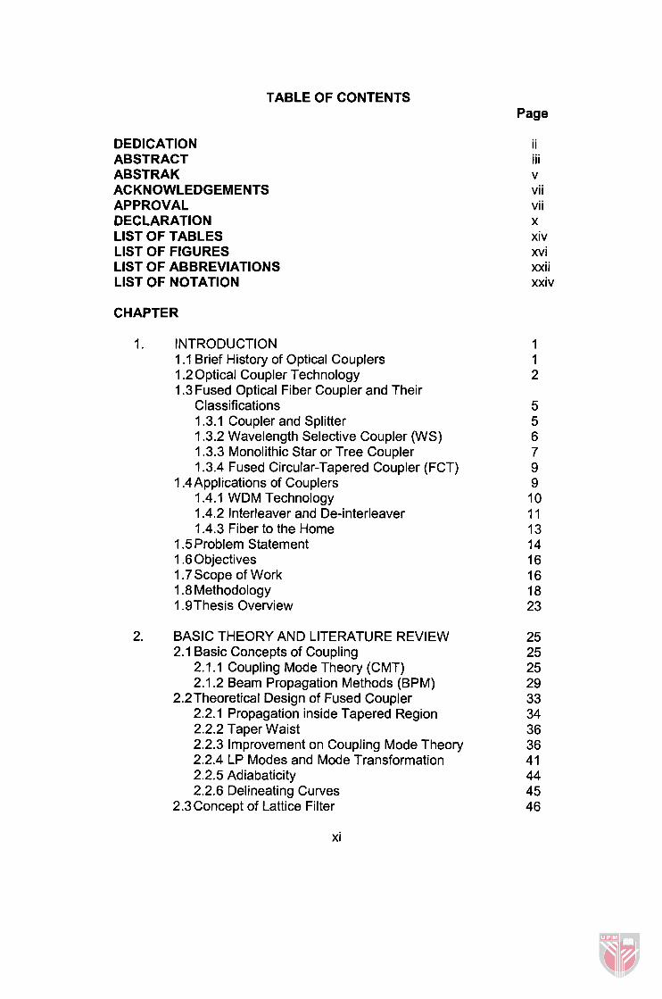
TABLE OF CONTENTS Page
DEDICATION ABSTRACT ABSTRAK ACKNOWLEDGEMENTS APPROVAL DECLARATION LlST OF TABLES LlST OF FIGURES LlST OF ABBREVIATIONS LlST OF NOTATION
CHAPTER
1. INTRODUCTION 1 .I Brief History of Optical Couplers 1.2 Optical Coupler Technology 1.3 Fused Optical Fiber Coupler and Their
Classifications 1.3.1 Coupler and Splitter 1.3.2 Wavelength Selective Coupler (WS) 1.3.3 Monolithic Star or Tree Coupler 1.3.4 Fused Circular-Tapered Coupler (FCT)
1.4Applications of Couplers 1.4.1 WDM Technology 1.4.2 lnterleaver and De-interleaver 1.4.3 Fiber to the Home
1.5 Problem Statement 1.6 Objectives 1.7 Scope of Work 1.8 Methodology 1.9Thesis Overview
2. BASIC THEORY AND LITERATURE REVIEW 2.1 Basic Concepts of Coupling
2.1 .I Coupling Mode Theory (CMT) 2.1.2 Beam Propagation Methods (BPM)
2.2Theoretical Design of Fused Coupler 2.2.1 Propagation inside Tapered Region 2.2.2 Taper Waist 2.2.3 Improvement on Coupling Mode Theory 2.2.4 LP Modes and Mode Transformation 2.2.5 Adiabaticity 2.2.6 Delineating Curves
2.3 Concept of Lattice Filter
ii iii v vii vi i X
xiv xvi xxii xxiv
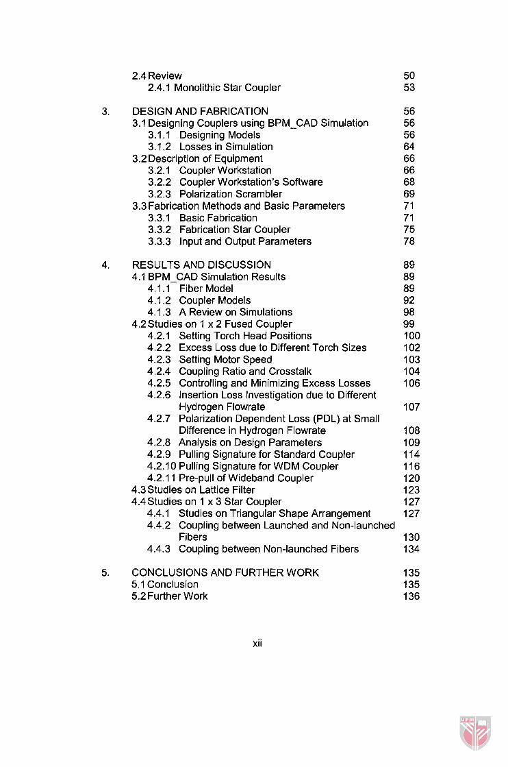
2.4 Review 2.4.1 Monolithic Star Coupler
DESIGN AND FABRICATION 3.1 Designing Couplers using BPM-CAD Simulation
3.1.1 Designing Models 3.1.2 Losses in Simulation
3.2 Description of Equipment 3.2.1 Coupler Workstation 3.2.2 Coupler Workstation's Software 3.2.3 Polarization Scrambler
3.3 Fabrication Methods and Basic Parameters 3.3.1 Basic Fabrication 3.3.2 Fabrication Star Coupler 3.3.3 Input and Output Parameters
RESULTS AND DISCUSSION 4.1 BPM-CAD Simulation Results
4.1.1 Fiber Model 4.1.2 Coupler Models 4.1.3 A Review on Simulations
4.2Studies on 1 x 2 Fused Coupler 4.2.1 Setting Torch Head Positions 4.2.2 Excess Loss due to Different Torch Sizes 4.2.3 Setting Motor Speed 4.2.4 Coupling Ratio and Crosstalk 4.2.5 Controlling and Minimizing Excess Losses 4.2.6 Insertion Loss Investigation due to Different
Hydrogen Flowrate 4.2.7 Polarization Dependent Loss (PDL) at Small
Difference in Hydrogen Flowrate 4.2.8 Analysis on Design Parameters 4.2.9 Pulling Signature for Standard Coupler 4.2.10 Pulling Signature for WDM Coupler 4.2.1 1 Pre-pull of Wideband Coupler
4.3 Studies on Lattice Filter 4.4 Studies on 1 x 3 Star Coupler
4.4.1 Studies on Triangular Shape Arrangement 4.4.2 Coupling between Launched and on-launched
Fibers 130 4.4.3 Coupling between Non-launched Fibers 1 34
CONCLUSIONS AND FURTHER WORK 5.1 Conclusion 5.2 Further Work
xii

REFERENCES APPENDICES BIODATA OF THE AUTHOR
xiii

LIST OF TABLES
Table
LP modes constituents
Ratio of cores for various models
Main specifications for Coupler Workstation
Set-up Parameters
Parameters shown by the FiberPro Software
Common set-up parameters for various types of couplers
Comparison between design and desired coupling ratios at
various coupling length for 1550 nm wavelength
Comparison in between design and actual
131 011 550 WDM coupler
Design and performance parameters for 1 x 3 star coupler
Definitions of parameters
lnput and output data for standard coupler
lnput and output data for standard coupler
lnput and output data for standard coupler
lnput and output data for 131 011 550 WDM coupler
lnput and output data for 131 011 550 WDM coupler
Data for theoretical design (Z = 0 mm to 1.24 mm)
Data for theoretical design (Z = 1.28 mm to 2.52 mm)
Data for theoretical design (Z = 2.56 mm to 3.80 mm)
Page
42
62
69
79
79
99
xiv

D l .4 Data for theoretical design (Z = 3.84 rnrn to 5.08 rnrn)
D l .5 Data for theoretical design (Z = 5.12 rnrn to 6.00 rnrn)
D2.1 Data for theoretical design (Z = 5.12 rnrn to 6.00 rnrn) of
wavelength 131 0 nrn

Figure
LIST OF FIGURES
Page
Cross-section's view of FBT coupler [ I ] taken at an
angle (photograph courtesy D.Mortimore, British
Telecom Research Laboratories)
Cross-section of FCT coupler before tapering process [2]
A 3 dB standard coupler 5
A coupler with complete packaging (A); a coupler covered by
heat shrinking tube (B); a coupler with exposed internal
view (C)
98011 550 WDM coupler
(i) 1 x 16 tree coupler using 1 x 2 coupler; (ii) 1 x 16 tree
coupler using 1 x 4 monolithic coupler
DWDM system [5]
A schematic of demultiplexer using de-interleaver [6]
One-stage lattice filter [8]
PON, simplified from [ I I ]
Scope of Work
I. I I a Research Methodology
I . I I b Fabrication method of fused couplers
I. I I c Production step of fused couplers
2.1 The refractive index distribution of the coupled slab
waveguides
xvi
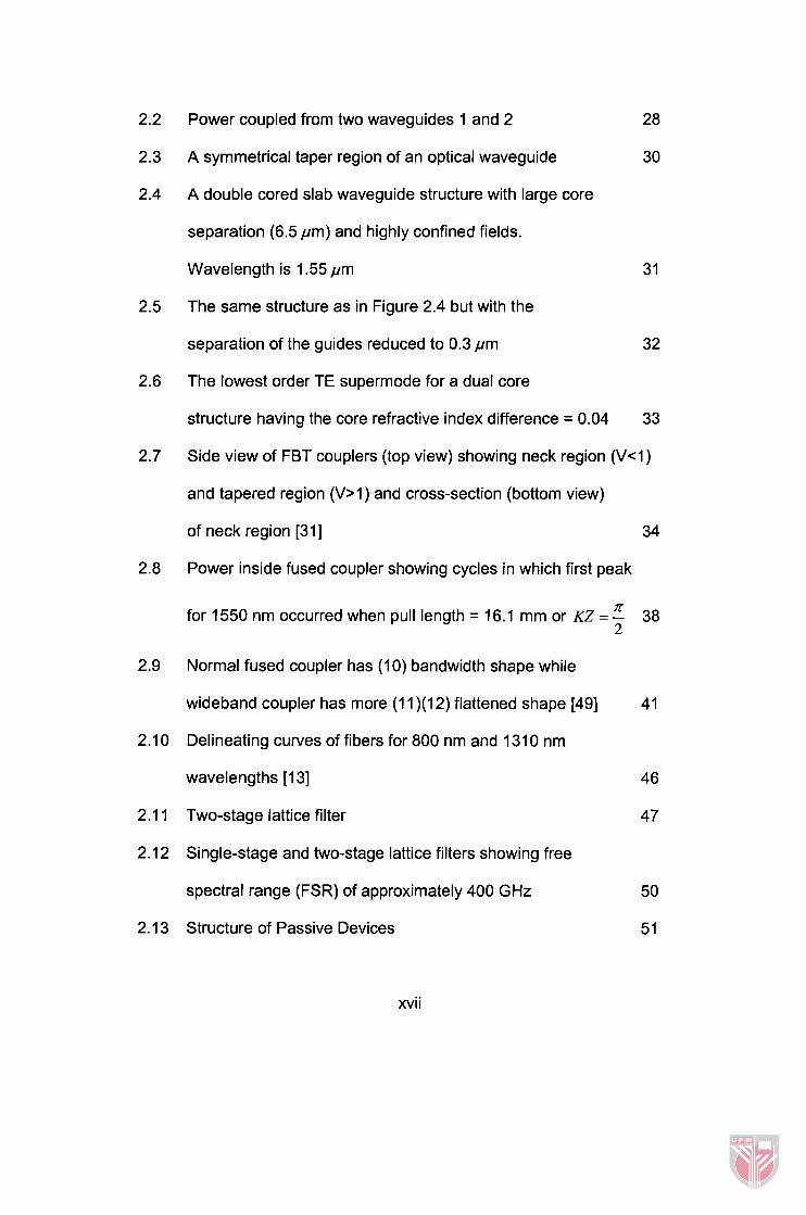
2.2 Power coupled from two waveguides 1 and 2
2.3 A symmetrical taper region of an optical waveguide
2.4 A double cored slab waveguide structure with large core
separation (6.5 pm) and highly confined fields.
Wavelength is 1.55 pm
2.5 The same structure as in Figure 2.4 but with the
separation of the guides reduced to 0.3 p m
2.6 The lowest order TE supermode for a dual core
structure having the core refractive index difference = 0.04 33
2.7 Side view of FBT couplers (top view) showing neck region ( V 4 )
and tapered region (V>1) and cross-section (bottom view)
of neck region [31] 34
2.8 Power inside fused coupler showing cycles in which first peak
n for 1550 nm occurred when pull length = 16.1 mm or KZ = - 38
2
2.9 Normal fused coupler has (10) bandwidth shape while
wideband coupler has more (1 1 )(I 2) flattened shape [49]
2.1 0 Delineating curves of fibers for 800 nm and 131 0 nm
wavelengths [ I 31
2.1 1 Two-stage lattice filter
2.12 Single-stage and two-stage lattice filters showing free
spectral range (FSR) of approximately 400 GHz
2.1 3 Structure of Passive Devices
xvi i
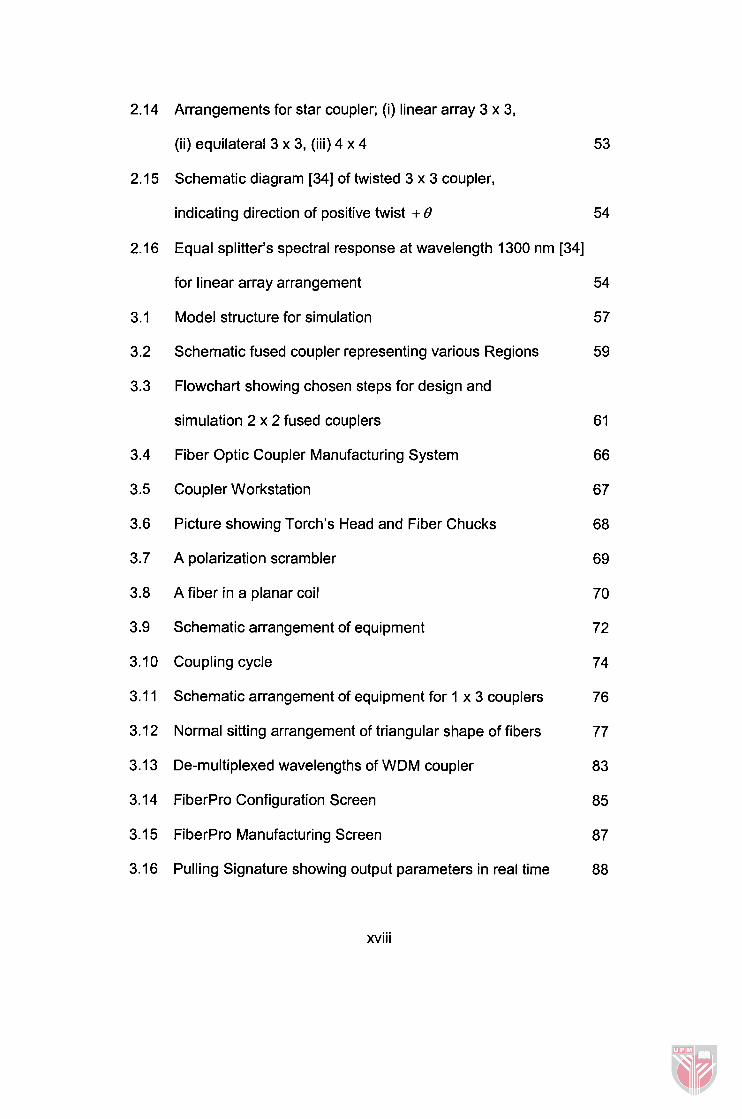
2.14 Arrangements for star coupler; (i) linear array 3 x 3,
(ii) equilateral 3 x 3, (iii) 4 x 4
2.15 Schematic diagram [34] of twisted 3 x 3 coupler,
indicating direction of positive twist + 8
2.1 6 Equal splitter's spectral response at wavelength 1300 nm [34]
for linear array arrangement
3.1 Model structure for simulation
3.2 Schematic fused coupler representing various Regions
3.3 Flowchart showing chosen steps for design and
simulation 2 x 2 fused couplers
3.4 Fiber Optic Coupler Manufacturing System
3.5 Coupler Workstation
3.6 Picture showing Torch's Head and Fiber Chucks
3.7 A polarization scrambler
3.8 A fiber in a planar coil
3.9 Schematic arrangement of equipment
3.10 Coupling cycle
3.1 1 Schematic arrangement of equipment for 1 x 3 couplers
3.12 Normal sitting arrangement of triangular shape of fibers
3.13 De-multiplexed wavelengths of WDM coupler
3.14 FiberPro Configuration Screen
3.1 5 FiberPro Manufacturing Screen
3.16 Pulling Signature showing output parameters in real time
xvi i i

V parameter versus core diameter for various wavelengths
(A=O. 0034 1 )
Comparison of small and big core ratios for tapered fiber
Coupling characteristic for core ratio 1 to 0.43
Coupling characteristic for core ratio 0.65 to 0.43
Coupling characteristic for core ratio 0.56 to 0.43
Coupling characteristic for core ratio 0.56 to 0.43
Coupling characteristic for core ratio 0.65 to 0.43
Coupling characteristic for core ratio 0.75 to 0.56
Actual Pulling Signature showing jump in excess loss occurred
at end of tapering process
Comparison of two different torch heads
The graph of distance versus runtime for equation
s=ll l t -91.41
Set coupling ratio versus actual coupling ratio for
1550 nm wavelength
Achieved coupling ratios at various crosstalk level for
131 011 550 WDM coupler
Relationship in between excess loss and elongation
Insertion loss versus hydrogen flowrate
Polarization dependent loss at small change of hydrogen
flowrate 109
Actual Pulling Signature showing various types of pull length 1 1 0
xix

4.18 a) Fiber at time = 0 s, a section PQ of fused length Lo is heated.
b) The structure of fiber taper representing cross-section
view after tapering
4.19 Lengths increase as waist diameter ratio decreases
4.20 Manufacturing Screen for an actual 3 dB coupler
4.21 Theoretical pulling signature which represents standard
coupler 115
4.22 Coupling coefficient increases as tapering process continues 11 6
4.23 Actual Pulling Signature showing both power for 1480 nm
and 161 0 nm wavelengths launched initially at both input
ports simultaneously 1 17
4.24 Actual Pulling Signature showing both power for 1480 nm and
1550 nm wavelengths launched initially at both input ports
simultaneously 1 18
4.25 Theoretical pulling signature showing de-multiplexing point 1 19
4.26 Comparison of coupling coefficient between identical (b=l) and
non-identical fibers' diameters (b=0.82)
4.27 Theoretical pulling signature for wideband coupler
4.28 Power taken for various couplers with different diameters'
ratios at first coupling cycle
4.29 A 1550 nm LED broadband input signal viewed from
Optical Spectrum Analyzer
4.30 Interleaved output signal at first port showing odd
wavelengths centred at 1548.5 nm 125
4.31 Interleaved output signal showing channel spacing = 2.84 nm
or FSR = 178 GHz 126
4.32 Superimposed output signals showing both odd and
even wavelengths overlapping each other
4.33 Arrows showing first rotation
4.34 Arrows showing second rotation
4.35 Two possible positions at fusion region for the intertwined
twist method
4.36 Arrows showing the opposite rotation for second step of twist 128
4.37 Two possible worst positions for normal twisting 129
4.38 Possible position under 420" rotation for truly equilateral
arrangement
4.39 Actual Pulling Signature for 1 x 3 star coupler with unequal
splitting ratio
4.40 Actual Pulling Signature for 1 x 3 star coupler at wavelength
of 131 0 nm 132
4.41 Output power 4 (red) and output powere (blue) shows unequal
powers between them for truly equilateral arrangement 1 34
5.1 Recommended modification for Coupler Workstation 137
C. l Relationship between power and Volt 150
xxi

BPM
CAD
CH
CMT
CPU
CR
CW
CWDM
DWDM
EL
FBT
FTP
FTTH
I L
ITU
LM
MFD
MZI
OLT
ONU
OSA
PDL
LIST OF ABBREVIATIONS
Beam Propagation Method
Computer Aided Design
Photodetector
Coupled Mode Theory
Central Processing Unit
Coupling Ratio
Coupler Workstation
Coarse Wavelength Division Multiplexing
Dense Wavelength Division Multiplexing
Excess Loss
Fused Biconical Taper
Flame Torch Position
Fiber to the Home
Insertion Loss
International Telecomunication Union
Lower Modes
Mode Field Diameter
Mach Zehnder lnteferometer
Optical Line Terminal
Optical Network Unit
Optical Spectrum Analyzer
Polarization Dependent Loss
xxii

PON
SMF
WDM
WSF
Pull Length
Passive Optical Network
Single Mode Fiber
Wavelength Division Multiplexing
Wavelength Selective Fused
xxiii