
TM-m50 Technical Reference Guide
138
Technical Reference Guide Describes features of the product. Describes setup and installation of the product and peripherals. Describes advanced usage methods for the product. Describes how to control the printer and necessary information when you develop applications. Describes how to handle the product. Describes general specifications and character code tables. M00132200 Rev. A Product Overview Setup Advanced Usage Application Development Information Handling Appendix
Transcript of TM-m50 Technical Reference Guide
Technical Reference Guide
Describes features of the product.
Describes setup and installation of the product and peripherals.
Describes advanced usage methods for the product.
Describes how to control the printer and necessary information when you develop applications.
Describes how to handle the product.
Describes general specifications and character code tables.
M00132200Rev. A
Product Overview
Setup
Advanced Usage
Application Development Information
Handling
Appendix
Cautions• No part of this document may be reproduced, stored in a retrieval system, or transmitted in any form or by
any means, electronic, mechanical, photocopying, recording, or otherwise, without the prior written permission of Seiko Epson Corporation.
• The contents of this document are subject to change without notice. Please contact us for the latest information.
• While every precaution has been taken in the preparation of this document, Seiko Epson Corporation assumes no responsibility for errors or omissions.
• Neither is any liability assumed for damages resulting from the use of the information contained herein.• Neither Seiko Epson Corporation nor its affiliates shall be liable to the purchaser of this product or third
parties for damages, losses, costs, or expenses incurred by the purchaser or third parties as a result of: accident, misuse, or abuse of this product or unauthorized modifications, repairs, or alterations to this product, or (excluding the U.S.) failure to strictly comply with Seiko Epson Corporation’s operating and maintenance instructions.
• Seiko Epson Corporation shall not be liable against any damages or problems arising from the use of any options or any consumable products other than those designated as Original Epson Products or Epson Approved Products by Seiko Epson Corporation.
TrademarksEPSON is a registered trademark of Seiko Epson Corporation.Exceed Your Vision and ESC/POS are registered trademarks or trademarks of Seiko Epson Corporation.Microsoft and Windows are registered trademarks of Microsoft Corporation in the United States and/or other countries.Wi-Fi®, WPATM, and WPA2TM are either registered trademarks or trademarks of Wi-Fi Alliance®.The Bluetooth® word mark and logos are registered trademarks owned by Bluetooth SIG, Inc. and any use of such marks by Seiko Epson Corporation is under license.IOS is a trademark or registered trademark of Cisco in the U.S. and other countries and is used under license.Apple, Apple TV, Apple Watch, iPad, iPad Air, iPad Pro, iPhone, and Lightning are trademarks of Apple Inc., registered in the U.S. and other countries. tvOS is a trademark of Apple Inc.AndroidTM is a trademark of Google LLC.Google Play and the Google Play logo are trademarks of Google LLC.All other trademarks are the property of their respective owners and used for identification purpose only.
ESC/POS® Command SystemEpson ESC/POS is a proprietary POS printer command system that includes patented or patent-pending commands. ESC/POS is compatible with most Epson POS printers and displays.ESC/POS is designed to reduce the processing load on the host computer in POS environments. It comprises a set of highly functional and efficient commands and also offers the flexibility to easily make future upgrades.
©Seiko Epson Corporation 2020. All rights reserved.
3
For Safety
Key to Symbols
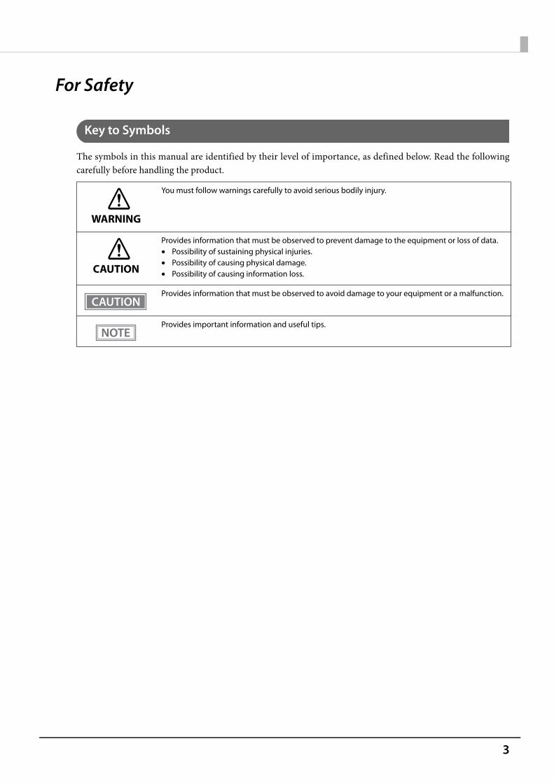
The symbols in this manual are identified by their level of importance, as defined below. Read the followingcarefully before handling the product.
WARNING
You must follow warnings carefully to avoid serious bodily injury.
CAUTION
Provides information that must be observed to prevent damage to the equipment or loss of data.• Possibility of sustaining physical injuries.• Possibility of causing physical damage.• Possibility of causing information loss.
Provides information that must be observed to avoid damage to your equipment or a malfunction.
Provides important information and useful tips.
4
Warnings
WARNING
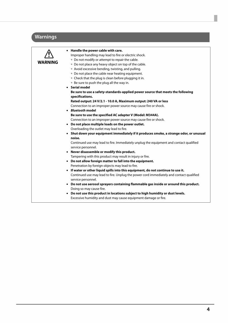
• Handle the power cable with care.Improper handling may lead to fire or electric shock.∗ Do not modify or attempt to repair the cable.∗ Do not place any heavy object on top of the cable.∗ Avoid excessive bending, twisting, and pulling.∗ Do not place the cable near heating equipment.∗ Check that the plug is clean before plugging it in.∗ Be sure to push the plug all the way in.
• Serial modelBe sure to use a safety-standards-applied power source that meets the following specifications.Rated output: 24 V/2.1 - 10.0 A, Maximum output: 240 VA or lessConnection to an improper power source may cause fire or shock.
• Bluetooth modelBe sure to use the specified AC adapter V (Model: M344A).Connection to an improper power source may cause fire or shock.
• Do not place multiple loads on the power outlet.Overloading the outlet may lead to fire.
• Shut down your equipment immediately if it produces smoke, a strange odor, or unusual noise.Continued use may lead to fire. Immediately unplug the equipment and contact qualified service personnel.
• Never disassemble or modify this product.Tampering with this product may result in injury or fire.
• Do not allow foreign matter to fall into the equipment.Penetration by foreign objects may lead to fire.
• If water or other liquid spills into this equipment, do not continue to use it.Continued use may lead to fire. Unplug the power cord immediately and contact qualified service personnel.
• Do not use aerosol sprayers containing flammable gas inside or around this product.Doing so may cause fire.
• Do not use this product in locations subject to high humidity or dust levels.Excessive humidity and dust may cause equipment damage or fire.
5
Cautions
Restriction of UseWhen this product is used for applications requiring high reliability/safety, such as transportation devicesrelated to aviation, rail, marine, automotive, etc.; disaster prevention devices; various safety devices, etc.; orfunctional/precision devices, etc., you should use this product only after giving consideration to including fail-safes and redundancies into your design to maintain safety and total system reliability. Because this product wasnot intended for use in applications requiring extremely high reliability/safety, such as aerospace equipment,main communication equipment, nuclear power control equipment, or medical equipment related to directmedical care, etc., please make your own judgment on this product's suitability after a full evaluation.
Note about interference• This product generates, uses, and can radiate radio frequency energy and, if not installed and used in
accordance with the instruction manual, may cause harmful interference to radio communications.• If this equipment does cause harmful interference to radio or television reception, which can be determined
by turning the equipment off and on, the user is encouraged to try to correct the interference by one or more of the following measures: - Reorient or relocate the receiving antenna for the radio/TV. - Increase the separation between the equipment and the radio/TV. - Connect the equipment into an outlet on a circuit different from that to which the receiver is connected. - Consult your dealer or an experienced radio/TV technician for help.
• Never disassemble or modify this product.• Seiko Epson Corporation shall not be liable for interference to radio/TV resulting from changes or
modifications to this product not expressly approved by Seiko Epson Corporation.
CAUTION
• Do not connect cables in ways other than those mentioned in this manual.Different connections may cause equipment damage.
• Be sure to set this equipment on a firm, stable, horizontal surface.The product may break or cause injury if it falls.
• Do not place heavy objects on top of this product. Never stand or lean on this product.Equipment may fall or collapse, causing breakage and possible injury.
• Take care not to injure your fingers on the manual cutter∗ When you remove printed paper∗ When you perform other operations such as loading/replacing roll paper
• Do not open the roll paper cover without taking the necessary precautions, as this can result in injury from the autocutter fixed blade.
• To ensure safety, unplug this product before leaving it unused for an extended period.• To avoid risk of electric shock, do not set up this product or handle cables during a
thunderstorm.• Never insert or disconnect the power plug with wet hands.
Doing so may result in severe shock.• Never attempt to repair this product yourself.
Improper repair work can be dangerous.

6
Open Source Software LicenseThis product uses open source software in addition to Epson proprietary software.For information of the open source software used in this product, see the following URL.http://xxx.xxx.xxx.xxx/licenses.htmlFor “xxx.xxx.xxx.xxx” in the above URL, input your printer’s IP address.
7
About this Manual
Aim of the Manual
This manual was created to provide information on development, design, and installation of POS systems anddevelopment and design of printer applications for developers.
Manual Content
The manual is made up of the following sections:
Chapter 1 Product Overview
Chapter 2 Setup
Chapter 3 Advanced Usage
Chapter 4 Application Development Information
Chapter 5 Handling
Appendix Product SpecificationsSpecifications of Interface and ConnectorBluetooth Low Energy Technology AdvertisingCharacter Code TablesCompatibility with USB Type-A
8
Contents■ For Safety..................................................................................................................................3
Key to Symbols.................................................................................................................................................................. 3Warnings ............................................................................................................................................................................. 4Cautions............................................................................................................................................................................... 5
■ Restriction of Use ....................................................................................................................5
■ Note about interference ........................................................................................................5
■ Open Source Software License.............................................................................................6
■ About this Manual ..................................................................................................................7Aim of the Manual ........................................................................................................................................................... 7Manual Content ................................................................................................................................................................ 7
■ Contents....................................................................................................................................8
Product Overview .......................................................................................... 12
■ Features ................................................................................................................................. 12
■ Product Configurations ...................................................................................................... 14Models................................................................................................................................................................................14NFC Tag ..............................................................................................................................................................................14Accessories .......................................................................................................................................................................15
■ Part Names and Functions ................................................................................................. 16
Panel LED ..........................................................................................................................................................................17Connectors .......................................................................................................................................................................18Online and Offline..........................................................................................................................................................20
■ Status and Errors .................................................................................................................. 21
Status Display ..................................................................................................................................................................21Bluetooth Connection Status ....................................................................................................................................22Network Connection Status .......................................................................................................................................23Error Status .......................................................................................................................................................................23
■ NV Memory (Non-Volatile Memory) ................................................................................. 25NV Graphics Memory....................................................................................................................................................25User NV Memory ............................................................................................................................................................25Memory Switches (customized values)..................................................................................................................25R/E (Receipt Enhancement)........................................................................................................................................25Maintenance Counter...................................................................................................................................................26
■ Simple Setup for Wireless LAN .......................................................................................... 27
■ Useful Functions for Smart Devices.................................................................................. 28
NFC Tag ..............................................................................................................................................................................28QR Code.............................................................................................................................................................................28
■ Printing Using Multiple Interfaces.................................................................................... 29
9
Setup ............................................................................................................... 30
■ Flow of Setup ........................................................................................................................ 30
■ Installing the Printer............................................................................................................ 31Changing to the Front Eject Position......................................................................................................................32
■ Changing the Paper Width ................................................................................................. 33
■ Connecting the Optional Wireless LAN Unit................................................................... 35
■ Connecting the Optional Customer Display................................................................... 36
■ Connecting the Optional External Buzzer....................................................................... 37
Attachment Position .....................................................................................................................................................37
■ Connecting the Cash Drawer ............................................................................................. 38
Required specifications of cash drawers................................................................................................................38Connecting the drawer kick cable ...........................................................................................................................39
■ Connecting to the Power Source ...................................................................................... 40
Connecting the AC cable.............................................................................................................................................40
■ Connecting the Printer to the Host Devices.................................................................... 43
USB Interface ...................................................................................................................................................................43Ethernet Interface ..........................................................................................................................................................43Wireless LAN Interface..................................................................................................................................................43Bluetooth Interface .......................................................................................................................................................46
■ Attaching the Power Switch Cover ................................................................................... 49
■ Enabling the Roll Paper Near-End Detection.................................................................. 50
Advanced Usage ............................................................................................ 51
■ Software Settings................................................................................................................. 51Functions...........................................................................................................................................................................52
■ Network Settings ................................................................................................................. 60
Setup methods ...............................................................................................................................................................60Flow of Setup...................................................................................................................................................................60Setup using EpsonNet Config ...................................................................................................................................61Setup using EpsonNet Config (Web version).......................................................................................................62Setup using arp/ping commands ............................................................................................................................63MAC Address Confirmation ........................................................................................................................................64
■ Setting/Check Modes .......................................................................................................... 65
Self-test Mode .................................................................................................................................................................67NV Graphics Information Print Mode......................................................................................................................67Receipt Enhancement Information Print Mode ..................................................................................................68Software Setting Mode ................................................................................................................................................68Restore Default Values Mode.....................................................................................................................................70Interface Setup Mode...................................................................................................................................................71TM-Intelligent Settings Information Print Mode ................................................................................................73Peripheral Device Information Print Mode ...........................................................................................................73
10
Hexadecimal Dumping Mode ...................................................................................................................................74
■ Printing a Status Sheet........................................................................................................ 75
■ Resetting the Interface Settings ....................................................................................... 77
■ TM-Intelligent Function ...................................................................................................... 78Server direct print ..........................................................................................................................................................78Status Notification .........................................................................................................................................................78
■ Network Tethering (for iOS device and Bluetooth capable models only)................. 79
Tablet Devices Supported by the Network Tethering......................................................................................80Firmware Versions that Supports the Network Tethering ...............................................................................80Enabling the Tethering Function..............................................................................................................................80Connection Procedure .................................................................................................................................................81
Application Development Information....................................................... 83
■ Controlling the Printer ........................................................................................................ 83ePOS-Print XML...............................................................................................................................................................83ESC/POS.............................................................................................................................................................................83
■ Controlling the Cash Drawer.............................................................................................. 84
■ Controlling the Optional External Buzzer ....................................................................... 85
■ Software................................................................................................................................. 86Development Kit ............................................................................................................................................................86Drivers ................................................................................................................................................................................87Utilities ...............................................................................................................................................................................88Others.................................................................................................................................................................................88Download .........................................................................................................................................................................89
■ Application Development and Distribution for iOS ...................................................... 90
■ Notes on Printing Barcodes and Two-Dimensional Symbols ...................................... 90
Handling ......................................................................................................... 91
■ Installing Roll Paper............................................................................................................. 91
For the top eject position............................................................................................................................................91For the front eject position.........................................................................................................................................93
■ Removing Jammed Paper .................................................................................................. 95
■ Roll Paper Cover does not Open ....................................................................................... 96
■ Cleaning the Printer............................................................................................................. 97
Cleaning the Printer Case............................................................................................................................................97Cleaning the Thermal Head/Platen Roller.............................................................................................................97
■ Preparing for Transport....................................................................................................... 98
■ Removing/Attaching the Rear and Bottom Covers ....................................................... 99Removing the Covers....................................................................................................................................................99
11
Attaching the Covers ................................................................................................................................................. 101
Appendix....................................................................................................... 103
■ Product Specifications ...................................................................................................... 103
Printing Specifications .............................................................................................................................................. 105Character Specifications ........................................................................................................................................... 106Paper Specifications ................................................................................................................................................... 108Printable Area ............................................................................................................................................................... 109Printing and Cutting Positions ............................................................................................................................... 110Electrical Characteristics........................................................................................................................................... 110Environmental Conditions....................................................................................................................................... 111External Dimensions .................................................................................................................................................. 112
■ Specifications of Interface and Connector.................................................................... 114
USB Interface ................................................................................................................................................................ 114Network Interface ....................................................................................................................................................... 115Bluetooth Interface .................................................................................................................................................... 118RS-232 Serial Interface .............................................................................................................................................. 122NFC Tag ........................................................................................................................................................................... 124
■ Bluetooth Low Energy Technology Advertising........................................................... 125Introduction .................................................................................................................................................................. 125Dongle specifications ................................................................................................................................................ 125Procedure....................................................................................................................................................................... 125Changing the Bluetooth Low Energy Technology Advertising Packet.................................................... 126
■ Character Code Tables....................................................................................................... 137
■ Compatibility with USB Type-A ....................................................................................... 138
12
Chapter 1 Product Overview
Product OverviewThis chapter describes features of the product.
Features
Printing• High speed receipt printing is possible (350 mm/s maximum).• By using the "Batch rotate print (Upside Down)" function, you can print pages upside down to make it easier
to read the pages when they are ejected from the front side of the printer.• Supports a variety of language (ANK (includes Thai language)/Japanese/Simplified Chinese/Traditional
Chinese/Korean)
Handling• Compact and lightweight
Top eject position: 127 x 127 x 135 mm (5.0 × 5.0 × 5.3") Front eject position: 127 x 133 x 129 mm (5.0 × 5.2 × 5.1")Approx. 1.3 kg {2.87 lb}
• Easy drop-in paper loading.• You can connect to the printer from an interface, other than the mainly connected interface, and run print
operation, when mainly connected interface is not printing.• The near end detector is installed as standard equipment.• Ethernet, Bluetooth, and Wi-Fi connection status can be easily checked by viewing respective LED lights.• A mechanism that holds paper while feeding paper backward enables reduction of top margin of each label
during continuous printing.• Equipped with three USB Type-A ports for connecting the option devices.• The USB port for connecting a tablet computer; USB-A - Device Charging, can provide up to 2.1 A.* Interface on the printer connecting the printer to other devices varies by printer specification.
Software• TM-Intelligent function is equipped.
• Supports Server Direct Print that sends a request for print data from the product to the Web server at regular intervals.
• Supports status notification function, which enables the printer to send its status to a web server at a regular interval.
• NFC tag built into the printer unit for printing to a touched printer.• Printing triggered by bar code scan by smart device camera.• A utility for iOS/Android TM (Epson TM Utility for iOS/Android) for making printer settings is provided.
13
Chapter 1 Product Overview
• Printing of various types of bar codes, GS1-DataBar, and two-dimensional symbols (PDF417, QR code, MaxiCode, Composite Symbology, Aztec Code, DataMatrix) is supported.
• A maintenance counter function is supported.
Environment• Paper saving function is available.
Others• Paper eject position are selectable from top and front.• Optional Wireless LAN cable set, customer display, and external buzzer are available.• Optional wall hanging bracket is available to attach the printer to a wall.
14
Chapter 1 Product Overview
Product Configurations
Models
• Serial model• Bluetooth® model
* Available models may differ depending on the area.
NFC Tag
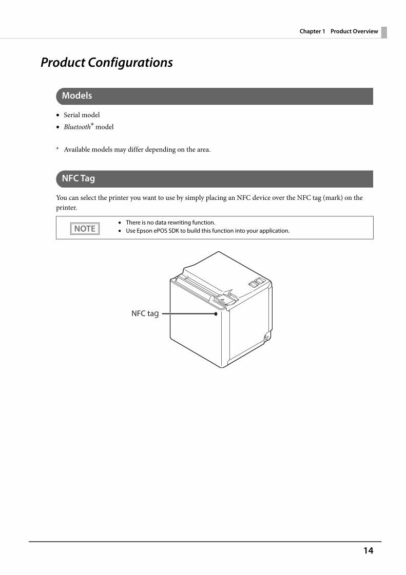
You can select the printer you want to use by simply placing an NFC device over the NFC tag (mark) on the printer.
• There is no data rewriting function.• Use Epson ePOS SDK to build this function into your application.
15
Chapter 1 Product Overview
Accessories
Included• 58-mm width roll paper guides• 80-mm width roll paper (for operation check)• Power switch cover• AC adapter• AC cable• Manuals
Options• Wireless LAN cable set (Model: OT-WL06)• Customer display (Model: DM-D30)• Optional external buzzer (Model: OT-BZ20)• Wall Hanging Bracket Set (Model: OT-WH30)• Back cover (Model: OT-CC30)
16
Chapter 1 Product Overview
Part Names and Functions
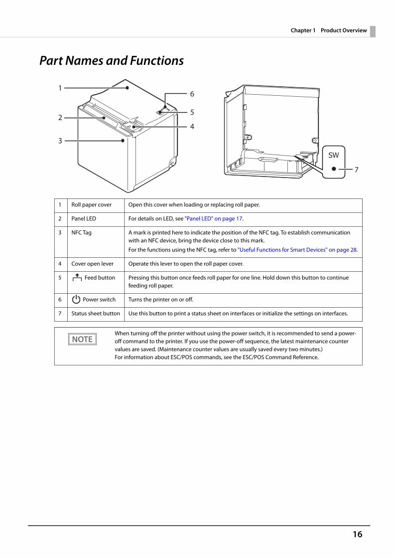
1 Roll paper cover Open this cover when loading or replacing roll paper.
2 Panel LED For details on LED, see "Panel LED" on page 17.
3 NFC Tag A mark is printed here to indicate the position of the NFC tag. To establish communication with an NFC device, bring the device close to this mark.
For the functions using the NFC tag, refer to "Useful Functions for Smart Devices" on page 28.
4 Cover open lever Operate this lever to open the roll paper cover.
5 Feed button Pressing this button once feeds roll paper for one line. Hold down this button to continue feeding roll paper.
6 Power switch Turns the printer on or off.
7 Status sheet button Use this button to print a status sheet on interfaces or initialize the settings on interfaces.
When turning off the printer without using the power switch, it is recommended to send a power-off command to the printer. If you use the power-off sequence, the latest maintenance counter values are saved. (Maintenance counter values are usually saved every two minutes.)For information about ESC/POS commands, see the ESC/POS Command Reference.
1
2
3
5
4
6
7
17
Chapter 1 Product Overview
Panel LED
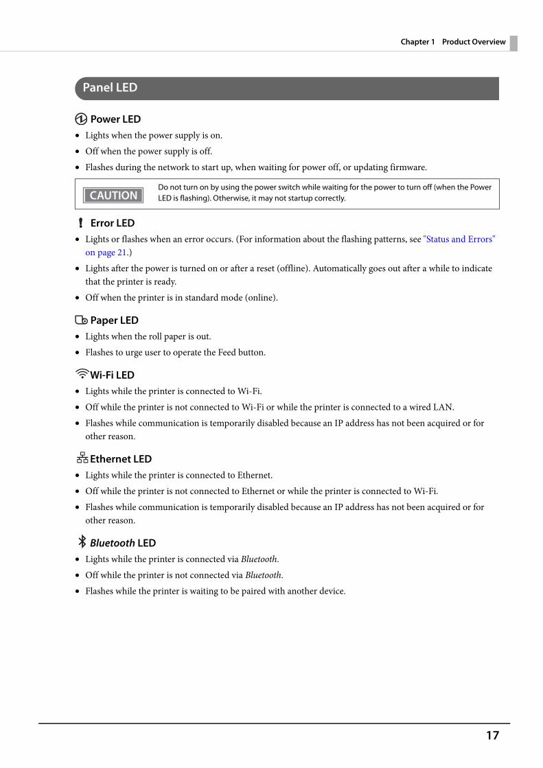
Power LED• Lights when the power supply is on.• Off when the power supply is off.• Flashes during the network to start up, when waiting for power off, or updating firmware.
Error LED• Lights or flashes when an error occurs. (For information about the flashing patterns, see "Status and Errors"
on page 21.)• Lights after the power is turned on or after a reset (offline). Automatically goes out after a while to indicate
that the printer is ready.• Off when the printer is in standard mode (online).
Paper LED• Lights when the roll paper is out.• Flashes to urge user to operate the Feed button.
Wi-Fi LED• Lights while the printer is connected to Wi-Fi.• Off while the printer is not connected to Wi-Fi or while the printer is connected to a wired LAN.• Flashes while communication is temporarily disabled because an IP address has not been acquired or for
other reason.
Ethernet LED• Lights while the printer is connected to Ethernet.• Off while the printer is not connected to Ethernet or while the printer is connected to Wi-Fi.• Flashes while communication is temporarily disabled because an IP address has not been acquired or for
other reason.
Bluetooth LED• Lights while the printer is connected via Bluetooth.• Off while the printer is not connected via Bluetooth.• Flashes while the printer is waiting to be paired with another device.
Do not turn on by using the power switch while waiting for the power to turn off (when the Power LED is flashing). Otherwise, it may not startup correctly.
18
Chapter 1 Product Overview
Connectors
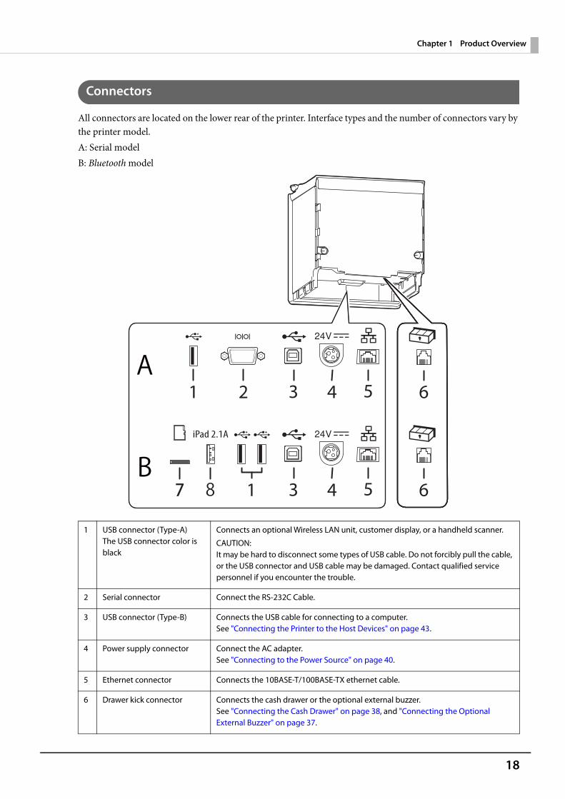
All connectors are located on the lower rear of the printer. Interface types and the number of connectors vary by the printer model.A: Serial modelB: Bluetooth model
1 USB connector (Type-A) The USB connector color is black
Connects an optional Wireless LAN unit, customer display, or a handheld scanner.
CAUTION:It may be hard to disconnect some types of USB cable. Do not forcibly pull the cable, or the USB connector and USB cable may be damaged. Contact qualified service personnel if you encounter the trouble.
2 Serial connector Connect the RS-232C Cable.
3 USB connector (Type-B) Connects the USB cable for connecting to a computer.See "Connecting the Printer to the Host Devices" on page 43.
4 Power supply connector Connect the AC adapter.See "Connecting to the Power Source" on page 40.
5 Ethernet connector Connects the 10BASE-T/100BASE-TX ethernet cable.
6 Drawer kick connector Connects the cash drawer or the optional external buzzer.See "Connecting the Cash Drawer" on page 38, and "Connecting the Optional External Buzzer" on page 37.
19
Chapter 1 Product Overview
7 microSD card slot For a special purpose and cannot be used for daily use. For more details, contact qualified service personnel.
8 USB connector (USB-A - Device Charging)The USB connector color is white
Connects a USB cable for connecting to a tablet computer.
• Bluetooth modelWhen connecting a Wireless LAN unit directly to the printer, connect it to the Type-A USB con-nector (black connector) in order to prevent the unit from contacting with the printer case.
• To communicate with a tablet computer via Bluetooth while charging the tablet through the USB connector (USB-A - Device Charging) on the printer, set the "Interface selection" setting to "Bluetooth only". For more details, see "Software Settings" on page 51.
• When connecting an Android device to the USB connector (USB-A – Device Charging) for data communication, make sure that the device satisfies the following requirements.Requirements: The version of Android OS is 10 or later with kernel version 4.9.15 or laterHowever, Epson does not guarantee normal operation of all Android devices even if they satisfy the requirements. Run some tests before actually using the device.
20
Chapter 1 Product Overview
Online and Offline
OnlineThe printer is online and ready for normal printing unless there is a reason to go offline.
OfflineThe printer automatically goes offline under the following conditions:• While the printer power is turning on/off• During the setting and check modes operating (except the hexadecimal dumping mode)• While roll paper is fed using the Feed button• When the printer stops printing due to a paper end (when the paper out detector detected the paper out) • During an operation standby state• When an error has occurred (See "Status and Errors" on page 21.)• While the roll paper cover is open
21
Chapter 1 Product Overview
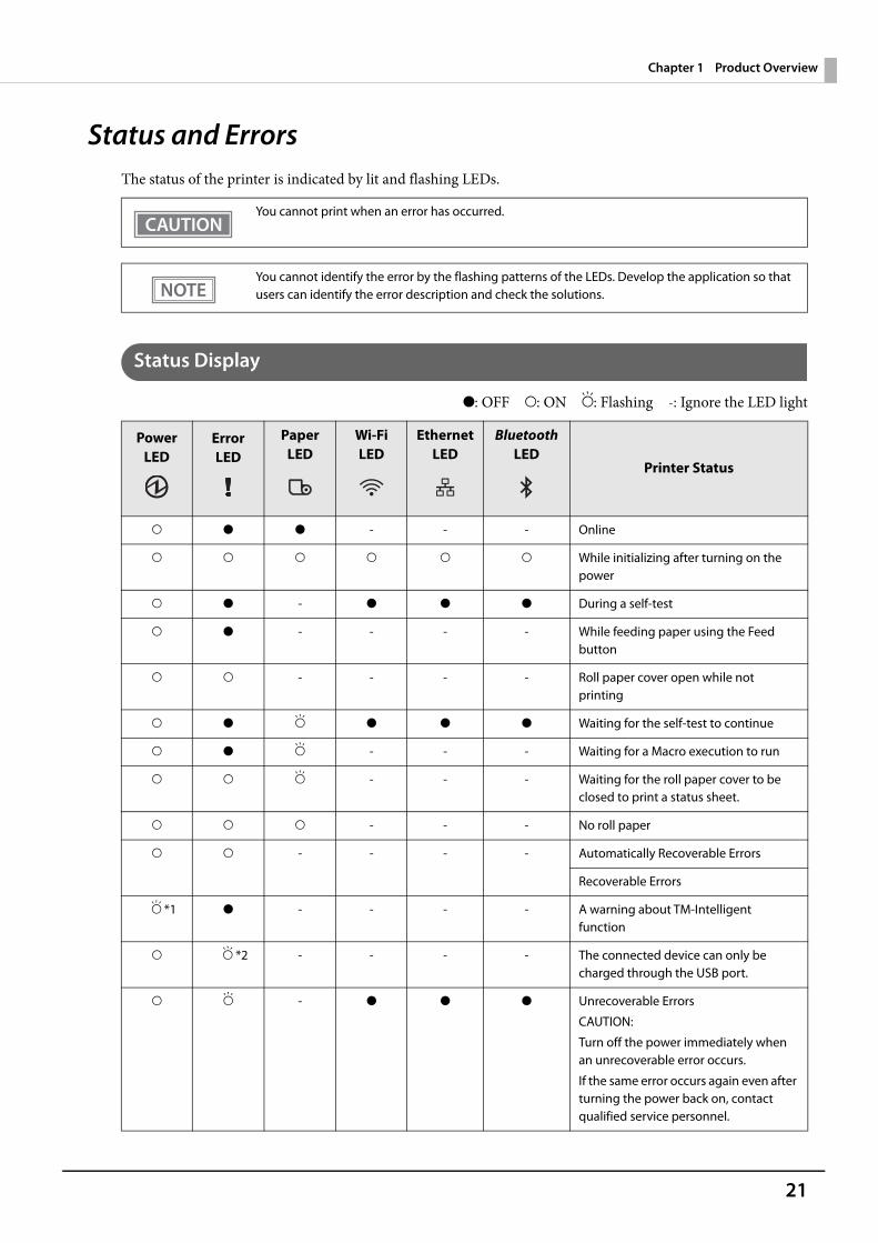
Status and ErrorsThe status of the printer is indicated by lit and flashing LEDs.
Status Display
O: OFF N: ON F: Flashing -: Ignore the LED light
You cannot print when an error has occurred.
You cannot identify the error by the flashing patterns of the LEDs. Develop the application so that users can identify the error description and check the solutions.
Power LED
Error LED
Paper LED
Wi-Fi LED
Ethernet LED
Bluetooth LED
Printer Status
N O O - - - Online
N N N N N N While initializing after turning on the power
N O - O O O During a self-test
N O - - - - While feeding paper using the Feed button
N N - - - - Roll paper cover open while not printing
N O F O O O Waiting for the self-test to continue
N O F - - - Waiting for a Macro execution to run
N N F - - - Waiting for the roll paper cover to be closed to print a status sheet.
N N N - - - No roll paper
N N - - - - Automatically Recoverable Errors
Recoverable Errors
F *1 O - - - - A warning about TM-Intelligent function
N F *2 - - - - The connected device can only be charged through the USB port.
N F - O O O Unrecoverable Errors
CAUTION:
Turn off the power immediately when an unrecoverable error occurs.
If the same error occurs again even after turning the power back on, contact qualified service personnel.
22
Chapter 1 Product Overview
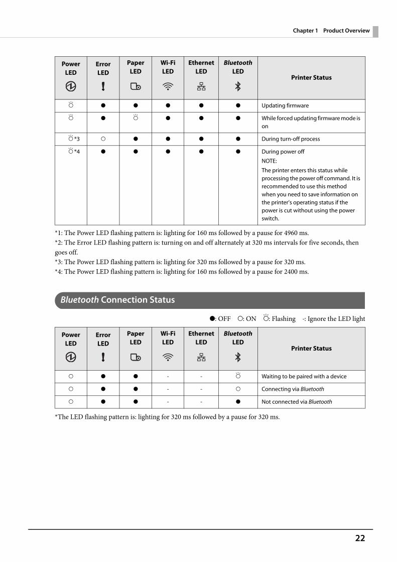
*1: The Power LED flashing pattern is: lighting for 160 ms followed by a pause for 4960 ms.*2: The Error LED flashing pattern is: turning on and off alternately at 320 ms intervals for five seconds, then goes off.*3: The Power LED flashing pattern is: lighting for 320 ms followed by a pause for 320 ms.*4: The Power LED flashing pattern is: lighting for 160 ms followed by a pause for 2400 ms.
Bluetooth Connection Status
O: OFF N: ON F: Flashing -: Ignore the LED light
*The LED flashing pattern is: lighting for 320 ms followed by a pause for 320 ms.
F O O O O O Updating firmware
F O F O O O While forced updating firmware mode is on
F *3 N O O O O During turn-off process
F *4 O O O O O During power off
NOTE:
The printer enters this status while processing the power off command. It is recommended to use this method when you need to save information on the printer’s operating status if the power is cut without using the power switch.
Power LED
Error LED
Paper LED
Wi-Fi LED
Ethernet LED
Bluetooth LED
Printer Status
N O O - - F Waiting to be paired with a device
N O O - - N Connecting via Bluetooth
N O O - - O Not connected via Bluetooth
Power LED
Error LED
Paper LED
Wi-Fi LED
Ethernet LED
Bluetooth LED
Printer Status
23
Chapter 1 Product Overview
Network Connection Status
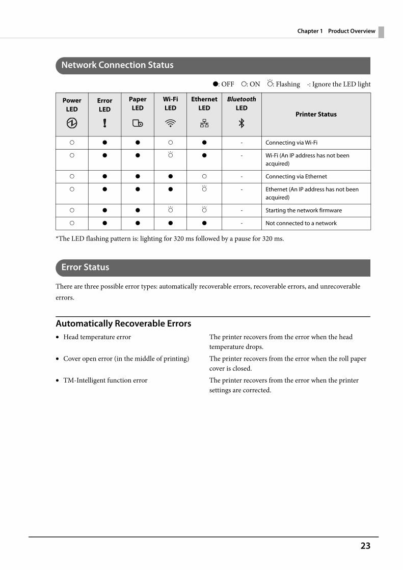
O: OFF N: ON F: Flashing -: Ignore the LED light
*The LED flashing pattern is: lighting for 320 ms followed by a pause for 320 ms.
Error Status
There are three possible error types: automatically recoverable errors, recoverable errors, and unrecoverableerrors.
Automatically Recoverable Errors• Head temperature error The printer recovers from the error when the head
temperature drops.• Cover open error (in the middle of printing) The printer recovers from the error when the roll paper
cover is closed.• TM-Intelligent function error The printer recovers from the error when the printer
settings are corrected.
Power LED
Error LED
Paper LED
Wi-Fi LED
Ethernet LED
Bluetooth LED
Printer Status
N O O N O - Connecting via Wi-Fi
N O O F O - Wi-Fi (An IP address has not been acquired)
N O O O N - Connecting via Ethernet
N O O O F - Ethernet (An IP address has not been acquired)
N O O F F - Starting the network firmware
N O O O O - Not connected to a network
24
Chapter 1 Product Overview
Recoverable Errors• Autocutter error An error occurs if the cutter is locked due to fallen foreign material or
similar cause. Although automatic recovery is performed even if there is only slight locking, if automatic recovery is not performed, remove foreign material and paper jams, and close the roll paper cover to perform recovery.
Unrecoverable Errors• These include a high voltage error, CPU execution error, and communication unit error. If the error persists
after turning the printer off and then on again, the printer may be defective. Contact qualified service personnel.
Instead of closing the roll paper cover, you can make the printer recover from the error using a dedicated command, however, doing so will cause the printer to go offline due to a cover open error.
Turn off the power immediately when an unrecoverable error occurs.
25
Chapter 1 Product Overview
NV Memory (Non-Volatile Memory)The printer's NV memory stores data even after the printer power is turned off. NV memory contains the following memory areas for the user:• NV graphics memory• User NV memory• Memory switches (customized values)• R/E (Receipt Enhancement)• Maintenance counter
NV Graphics Memory
Graphics, such as shop logos to be printed on receipts, can be registered.To register your graphics data, use TM-m50 Utility or ESC/POS commands.You can check registered graphics data using TM-m50 Utility or by printing the data in the NV graphics information print mode.
User NV Memory
You can store and read text data for multiple purposes, such as for storing a note including customizing or maintenance information of the printer.
Memory Switches (customized values)
With the memory switches, which are software switches for the printer, you can configure various settings of the printer. For information about the memory switch, see "Software Settings" on page 51.
R/E (Receipt Enhancement)
You can set the graphics data, such as a shop logo, registered in the NV graphics memory to be printed on the top of each receipt or to be printed on the bottom of each receipt just before the paper is cut.To make the settings, use TM-m50 Utility or ESC/POS commands.You can check the settings using TM-m50 Utility or by printing the settings information in the Receipt enhancement information print mode.
As a guide, NV memory rewriting should be used 10 times or less a day when you program applications.

26
Chapter 1 Product Overview
Maintenance Counter
With this function, printer information, such as the number of lines printed, the number of autocuts, and printer operation time after the printer starts working, is automatically stored in printer's memory. You can read the counter information to use it for periodical checks or part replacement.
• You can also check the head running length and number of times of autocutting with the self-test (see "Self-test Mode" on page 67).
• The maintenance counter values are automatically saved in the NV memory usually every twominutes (up to four minutes). However, the values are not saved when the printer is in power-saving mode or when it is turned off without the use of the power switch.
27
Chapter 1 Product Overview
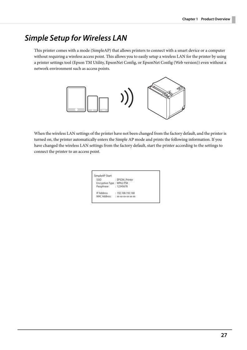
Simple Setup for Wireless LANThis printer comes with a mode (SimpleAP) that allows printers to connect with a smart device or a computer without requiring a wireless access point. This allows you to easily setup a wireless LAN for the printer by using a printer settings tool (Epson TM Utility, EpsonNet Config, or EpsonNet Config (Web version)) even without a network environment such as access points.
When the wireless LAN settings of the printer have not been changed from the factory default, and the printer is turned on, the printer automatically enters the Simple AP mode and prints the following information. If you have changed the wireless LAN settings from the factory default, start the printer according to the settings to connect the printer to an access point.
SimpleAP StartSSIDEncryption TypePassphrase
IP AddressMAC Address
: EPSON_Printer: WPA2-PSK: 12345678
: 192.168.192.168: xx-xx-xx-xx-xx-xx
28
Chapter 1 Product Overview
Useful Functions for Smart DevicesYou can easily connect this product to the network by using the NFC tag built-in to the printer or the QR codeprinted on the status sheet.
NFC Tag
Bring a smart device that supports NFC close to the NFC tag to acquire the printer information (information for specifying the device).By using the acquired information, the device can specify the printer to send a print job over a network or Bluetooth.
QR Code
Capture the QR code printed on the status sheet with the camera on your smart device to acquire the printer information (information for specifying the device).By using the acquired information, the device can specify the printer to send a print job over a network or Bluetooth.
• Programming using Epson ePOS SDK is required to use these functions. These functions arecreated by combining NFC touch and QR code capturing operations and the target printerspecifications using Printer Easy Select API.See the "Epson ePOS SDK for Android/iOS User's Manual" and the Epson ePOS SDK sampleprogram for more details. The sample program also contains a sample implementation method forreading an NFC tag and capturing a QR code.
• You can try a demo of these functions by using Epson TM Utility for iOS/Android.
29
Chapter 1 Product Overview
Printing Using Multiple InterfacesIn models with multiple interfaces, you can use all interfaces without any limitations on which interface is to be used. You can use this function to temporarily connect a smart device to a nearby printer and print.
The printer provides each interface with an independent receive buffer and switches the active interface depending on the priority, while handling data in each receive buffer.
You can set one interface for the main connection. Data received from the main connection interface is handled with the highest priority.By default, the interface that receives the first data transfer is set as the main connection interface; however, you can select the main connection interface in advance.
When the receive buffer for the active interface becomes empty and a preset time period (one second by default) has passed, switching to another interface is enabled, and an interface that receives print data becomes active.
When you do not use the Bluetooth function, set the Bluetooth security level to "Middle" or "High" to prevent unauthorized access to the printer over Bluetooth. You can change the security level by using Epson TM Utility, TM-m50 Utility, or in the Interface Setup mode.
You can select the main connection interface and set the time to enable interface switching from the software settings. For details on software settings, see "Software Settings" on page 51.
30
Chapter 2 Setup
SetupThis chapter describes setup and installation of the product and peripherals.
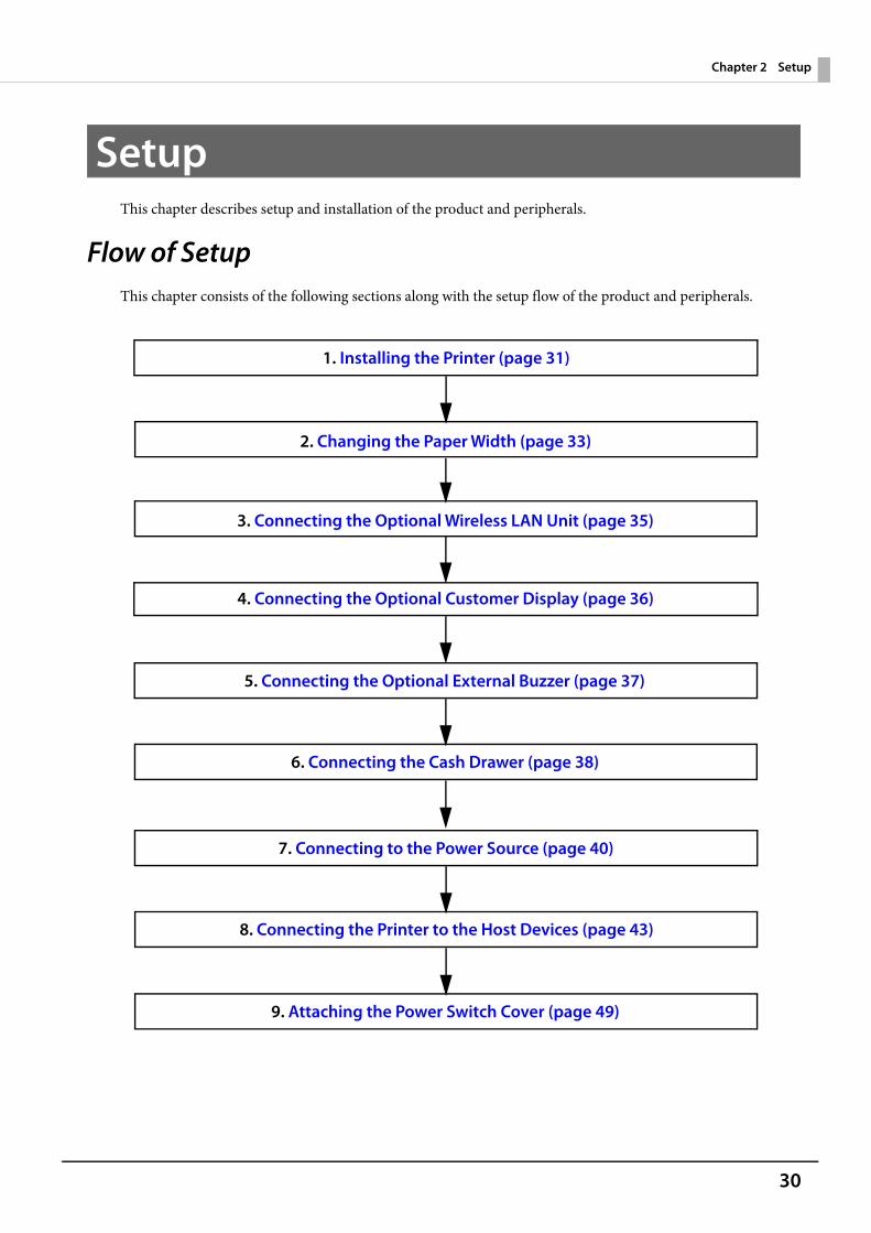
Flow of SetupThis chapter consists of the following sections along with the setup flow of the product and peripherals.
6. Connecting the Cash Drawer (page 38)
5. Connecting the Optional External Buzzer (page 37)
4. Connecting the Optional Customer Display (page 36)
3. Connecting the Optional Wireless LAN Unit (page 35)
1. Installing the Printer (page 31)
2. Changing the Paper Width (page 33)
8. Connecting the Printer to the Host Devices (page 43)
7. Connecting to the Power Source (page 40)
9. Attaching the Power Switch Cover (page 49)
31
Chapter 2 Setup
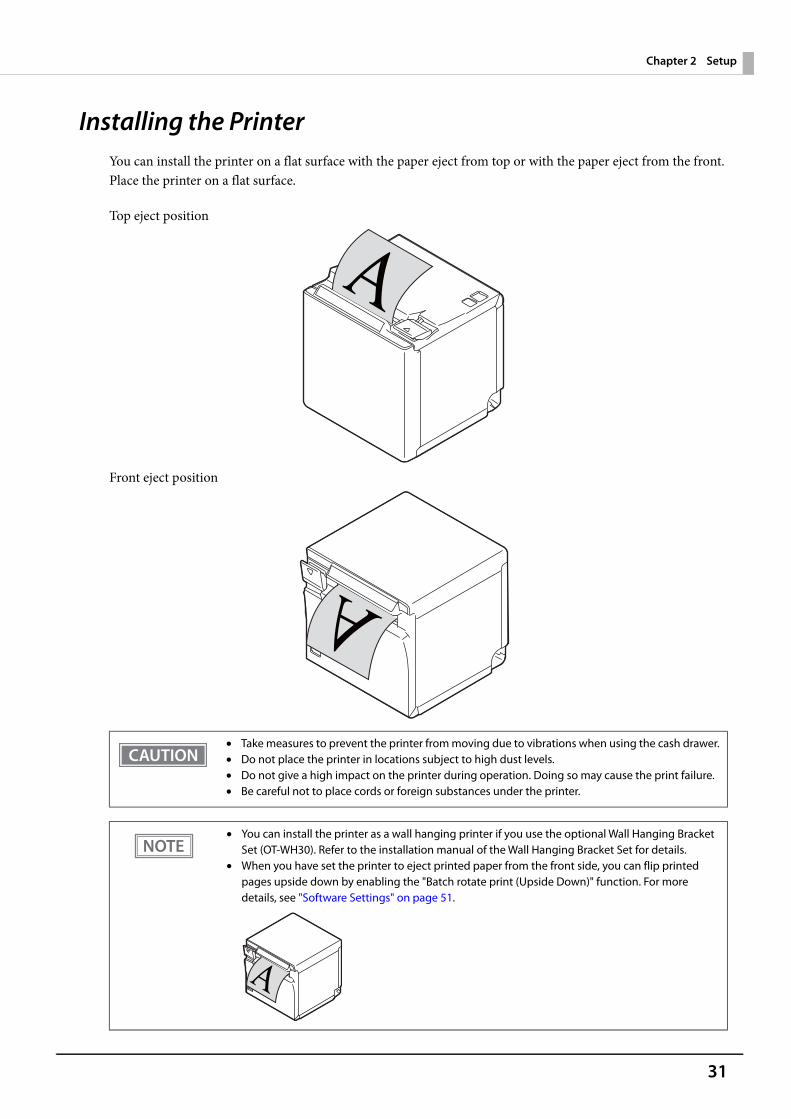
Installing the PrinterYou can install the printer on a flat surface with the paper eject from top or with the paper eject from the front.Place the printer on a flat surface.
Top eject position
Front eject position
• Take measures to prevent the printer from moving due to vibrations when using the cash drawer.• Do not place the printer in locations subject to high dust levels.• Do not give a high impact on the printer during operation. Doing so may cause the print failure.• Be careful not to place cords or foreign substances under the printer.
• You can install the printer as a wall hanging printer if you use the optional Wall Hanging Bracket Set (OT-WH30). Refer to the installation manual of the Wall Hanging Bracket Set for details.
• When you have set the printer to eject printed paper from the front side, you can flip printed pages upside down by enabling the "Batch rotate print (Upside Down)" function. For more details, see "Software Settings" on page 51.

32
Chapter 2 Setup
Changing to the Front Eject Position
You can change the eject position by replacing the rear cover and the bottom cover. At the time of purchase, paper is ejected from the top position. When changing to the front eject position, follow the steps below to replace the covers.
1 Remove the bottom cover and the rear cover. See the detailed information on "For the top eject position" on page 99.
2 Attach the rear cover and the bottom cover. See the detailed information on "For the front eject position" on page 102.
33
Chapter 2 Setup
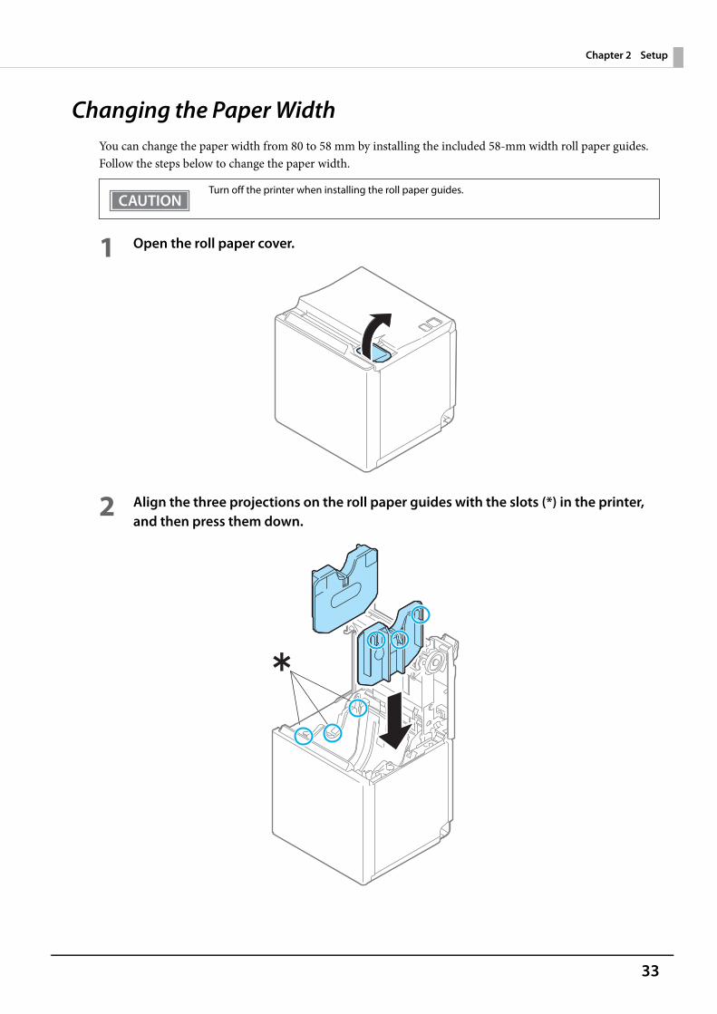
Changing the Paper WidthYou can change the paper width from 80 to 58 mm by installing the included 58-mm width roll paper guides. Follow the steps below to change the paper width.
1 Open the roll paper cover.
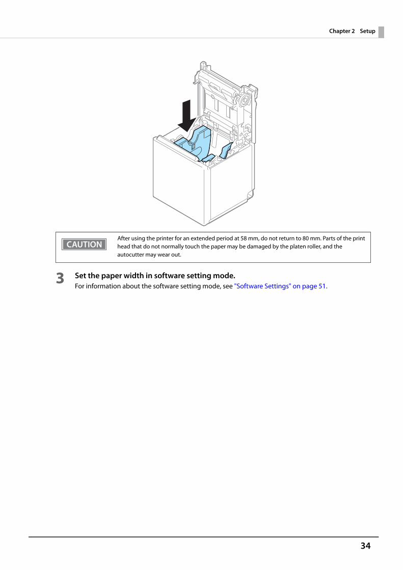
2 Align the three projections on the roll paper guides with the slots (*) in the printer, and then press them down.
Turn off the printer when installing the roll paper guides.
34
Chapter 2 Setup
3 Set the paper width in software setting mode. For information about the software setting mode, see "Software Settings" on page 51.
After using the printer for an extended period at 58 mm, do not return to 80 mm. Parts of the print head that do not normally touch the paper may be damaged by the platen roller, and the autocutter may wear out.
35
Chapter 2 Setup
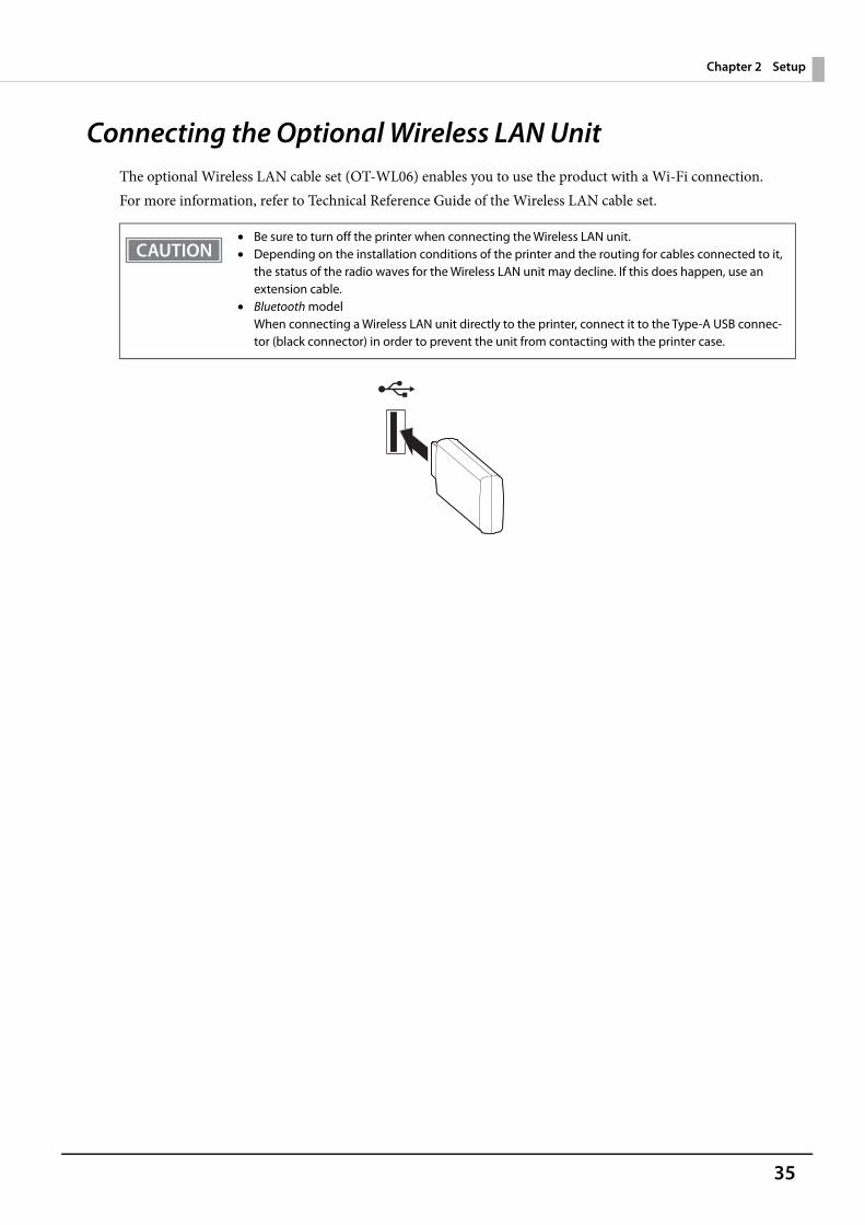
Connecting the Optional Wireless LAN UnitThe optional Wireless LAN cable set (OT-WL06) enables you to use the product with a Wi-Fi connection.For more information, refer to Technical Reference Guide of the Wireless LAN cable set.
• Be sure to turn off the printer when connecting the Wireless LAN unit.• Depending on the installation conditions of the printer and the routing for cables connected to it,
the status of the radio waves for the Wireless LAN unit may decline. If this does happen, use an extension cable.
• Bluetooth modelWhen connecting a Wireless LAN unit directly to the printer, connect it to the Type-A USB connec-tor (black connector) in order to prevent the unit from contacting with the printer case.
36
Chapter 2 Setup
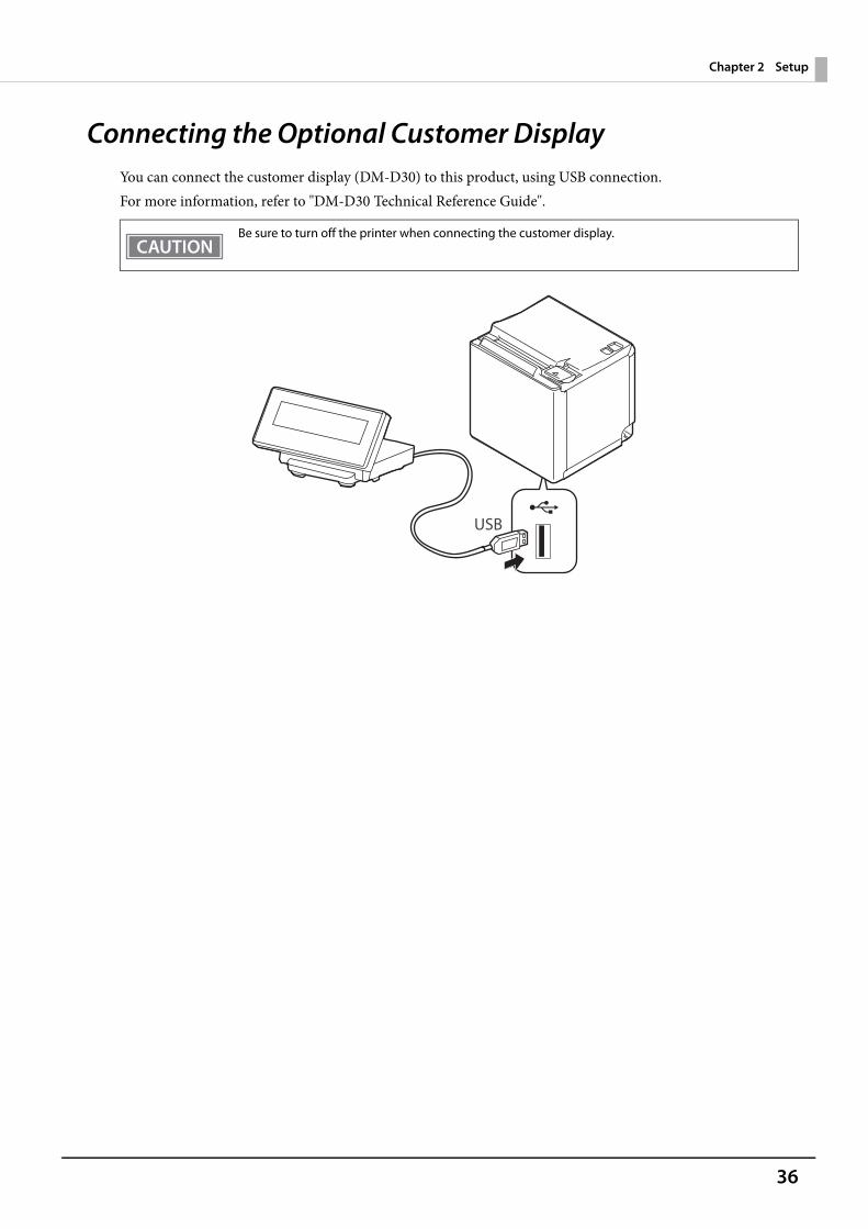
Connecting the Optional Customer DisplayYou can connect the customer display (DM-D30) to this product, using USB connection. For more information, refer to "DM-D30 Technical Reference Guide".
Be sure to turn off the printer when connecting the customer display.
37
Chapter 2 Setup
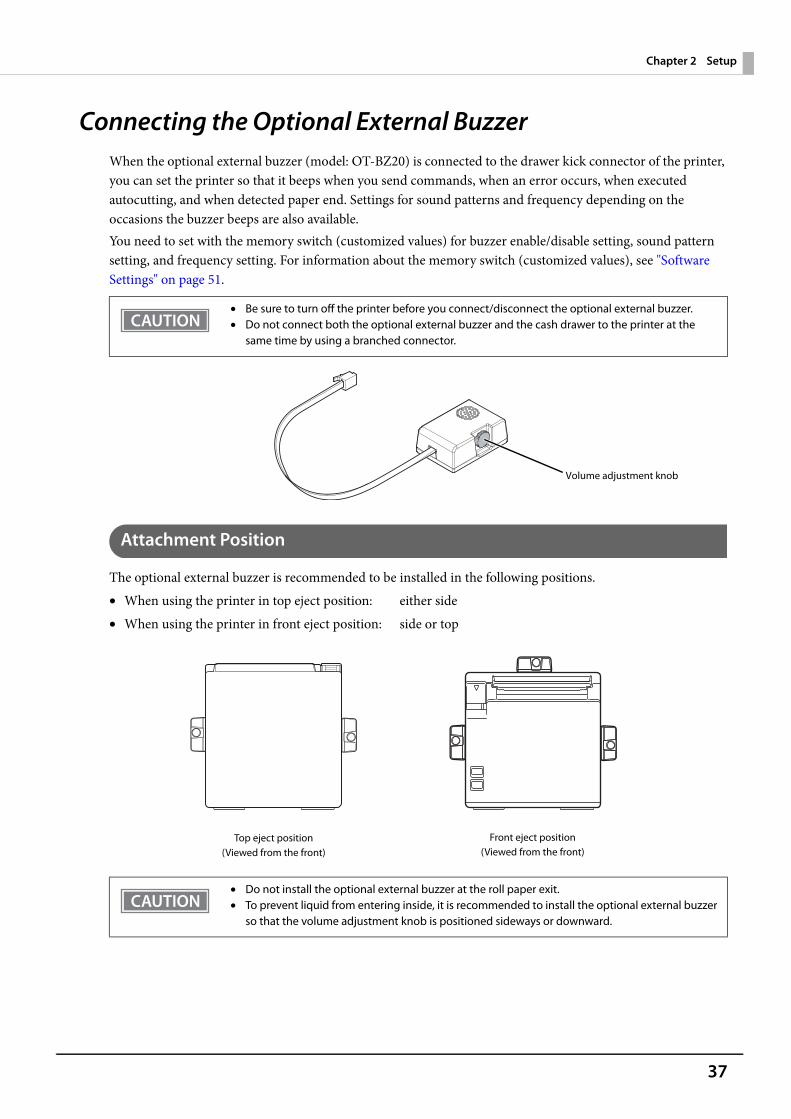
Connecting the Optional External BuzzerWhen the optional external buzzer (model: OT-BZ20) is connected to the drawer kick connector of the printer, you can set the printer so that it beeps when you send commands, when an error occurs, when executed autocutting, and when detected paper end. Settings for sound patterns and frequency depending on the occasions the buzzer beeps are also available.You need to set with the memory switch (customized values) for buzzer enable/disable setting, sound pattern setting, and frequency setting. For information about the memory switch (customized values), see "Software Settings" on page 51.
Attachment Position
The optional external buzzer is recommended to be installed in the following positions.• When using the printer in top eject position: either side• When using the printer in front eject position: side or top
• Be sure to turn off the printer before you connect/disconnect the optional external buzzer.• Do not connect both the optional external buzzer and the cash drawer to the printer at the
same time by using a branched connector.
• Do not install the optional external buzzer at the roll paper exit.• To prevent liquid from entering inside, it is recommended to install the optional external buzzer
so that the volume adjustment knob is positioned sideways or downward.
Volume adjustment knob
Top eject position(Viewed from the front)
Front eject position(Viewed from the front)
38
Chapter 2 Setup
Connecting the Cash Drawer
Required specifications of cash drawers
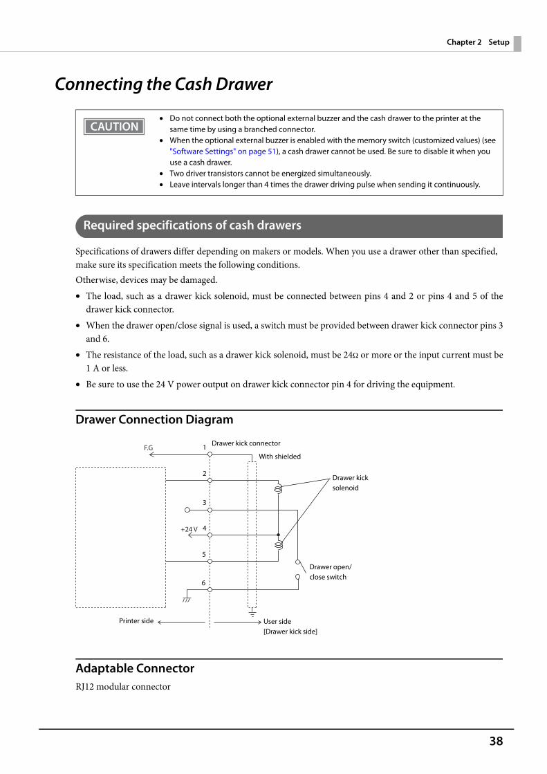
Specifications of drawers differ depending on makers or models. When you use a drawer other than specified, make sure its specification meets the following conditions.Otherwise, devices may be damaged.• The load, such as a drawer kick solenoid, must be connected between pins 4 and 2 or pins 4 and 5 of the
drawer kick connector.• When the drawer open/close signal is used, a switch must be provided between drawer kick connector pins 3
and 6.• The resistance of the load, such as a drawer kick solenoid, must be 24Ω or more or the input current must be
1 A or less.• Be sure to use the 24 V power output on drawer kick connector pin 4 for driving the equipment.
Drawer Connection Diagram
Adaptable ConnectorRJ12 modular connector
• Do not connect both the optional external buzzer and the cash drawer to the printer at the same time by using a branched connector.
• When the optional external buzzer is enabled with the memory switch (customized values) (see "Software Settings" on page 51), a cash drawer cannot be used. Be sure to disable it when you use a cash drawer.
• Two driver transistors cannot be energized simultaneously.• Leave intervals longer than 4 times the drawer driving pulse when sending it continuously.
F.G
+24 V
With shielded
Drawer kick connector
Printer side User side [Drawer kick side]
Drawer open/close switch
Drawer kick solenoid
1
2
3
4
5
6
39
Chapter 2 Setup
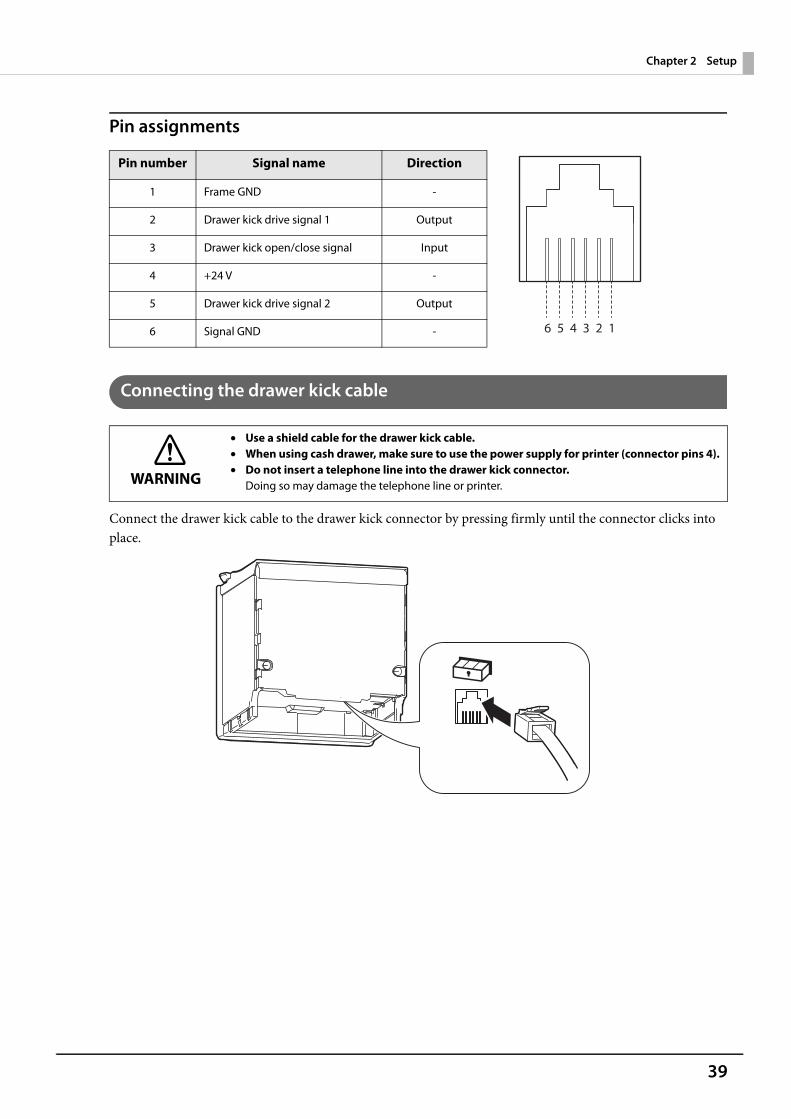
Pin assignments
Connecting the drawer kick cable
Connect the drawer kick cable to the drawer kick connector by pressing firmly until the connector clicks into place.
Pin number Signal name Direction
1 Frame GND -
2 Drawer kick drive signal 1 Output
3 Drawer kick open/close signal Input
4 +24 V -
5 Drawer kick drive signal 2 Output
6 Signal GND -
WARNING
• Use a shield cable for the drawer kick cable.• When using cash drawer, make sure to use the power supply for printer (connector pins 4).• Do not insert a telephone line into the drawer kick connector.
Doing so may damage the telephone line or printer.
6 5 4 3 2 1
40
Chapter 2 Setup
Connecting to the Power Source
Connecting the AC cable
1 Make sure the printer is turned off.
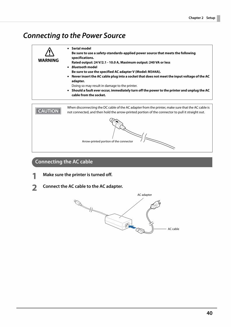
2 Connect the AC cable to the AC adapter.
WARNING
• Serial modelBe sure to use a safety-standards-applied power source that meets the following specifications.Rated output: 24 V/2.1 - 10.0 A, Maximum output: 240 VA or less
• Bluetooth modelBe sure to use the specified AC adapter V (Model: M344A).
• Never insert the AC cable plug into a socket that does not meet the input voltage of the AC adapter.Doing so may result in damage to the printer.
• Should a fault ever occur, immediately turn off the power to the printer and unplug the AC cable from the socket.
When disconnecting the DC cable of the AC adapter from the printer, make sure that the AC cable is not connected, and then hold the arrow-printed portion of the connector to pull it straight out.
Arrow-printed portion of the connector
AC cable
AC adapter
41
Chapter 2 Setup
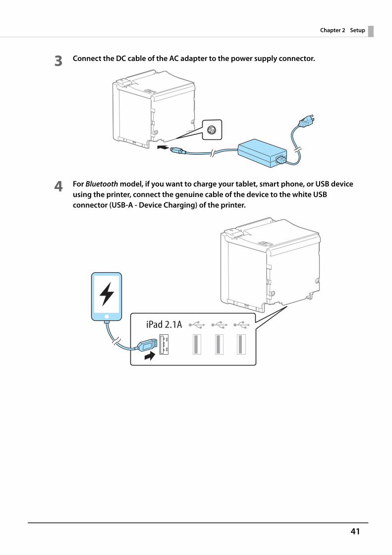
3 Connect the DC cable of the AC adapter to the power supply connector.
4 For Bluetooth model, if you want to charge your tablet, smart phone, or USB device using the printer, connect the genuine cable of the device to the white USB connector (USB-A - Device Charging) of the printer.
42
Chapter 2 Setup
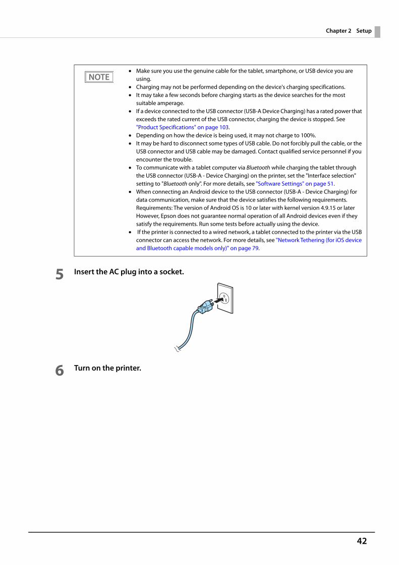
5 Insert the AC plug into a socket.
6 Turn on the printer.
• Make sure you use the genuine cable for the tablet, smartphone, or USB device you are using.
• Charging may not be performed depending on the device's charging specifications.• It may take a few seconds before charging starts as the device searches for the most
suitable amperage.• If a device connected to the USB connector (USB-A Device Charging) has a rated power that
exceeds the rated current of the USB connector, charging the device is stopped. See "Product Specifications" on page 103.
• Depending on how the device is being used, it may not charge to 100%.• It may be hard to disconnect some types of USB cable. Do not forcibly pull the cable, or the
USB connector and USB cable may be damaged. Contact qualified service personnel if you encounter the trouble.
• To communicate with a tablet computer via Bluetooth while charging the tablet through the USB connector (USB-A - Device Charging) on the printer, set the "Interface selection" setting to "Bluetooth only". For more details, see "Software Settings" on page 51.
• When connecting an Android device to the USB connector (USB-A - Device Charging) for data communication, make sure that the device satisfies the following requirements.Requirements: The version of Android OS is 10 or later with kernel version 4.9.15 or laterHowever, Epson does not guarantee normal operation of all Android devices even if they satisfy the requirements. Run some tests before actually using the device.
• If the printer is connected to a wired network, a tablet connected to the printer via the USB connector can access the network. For more details, see "Network Tethering (for iOS device and Bluetooth capable models only)" on page 79.
43
Chapter 2 Setup
Connecting the Printer to the Host Devices
USB Interface
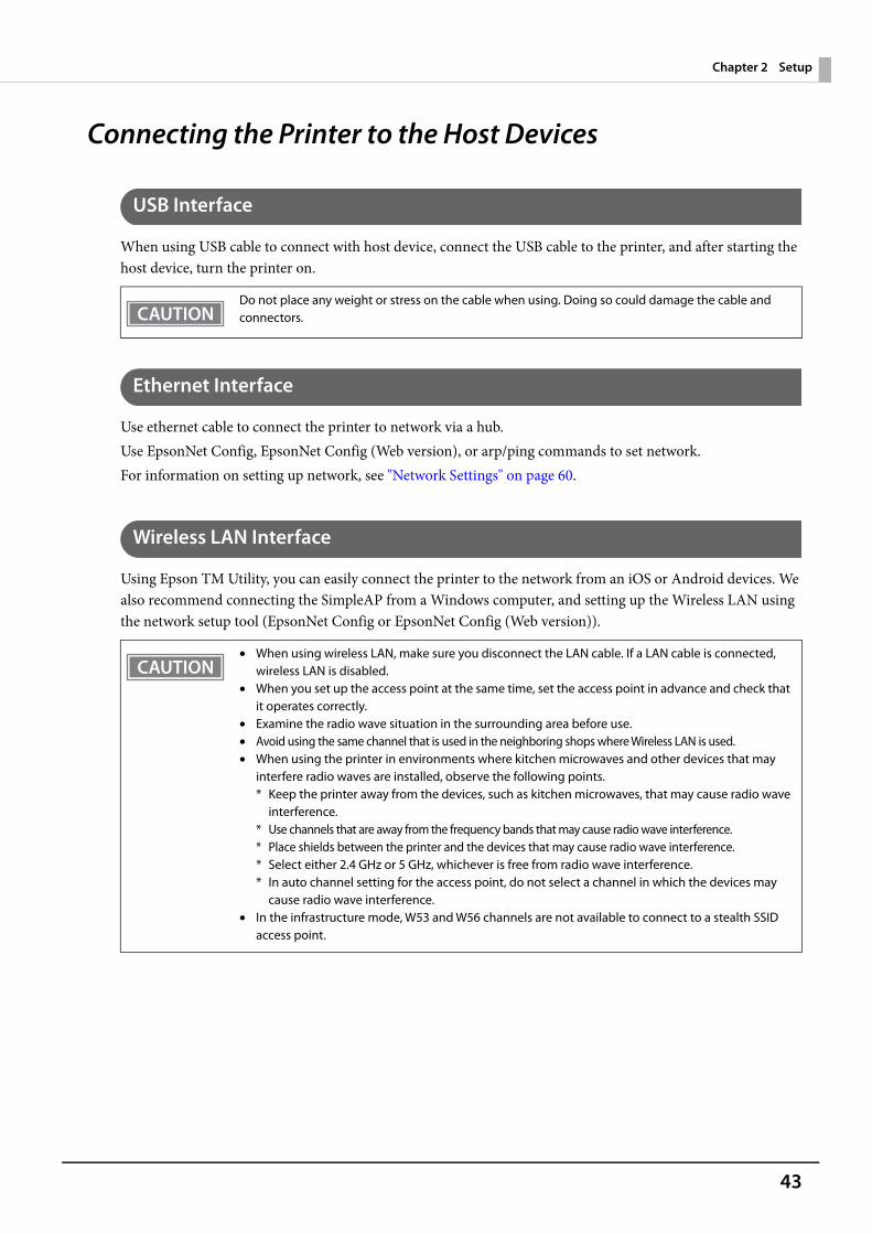
When using USB cable to connect with host device, connect the USB cable to the printer, and after starting the host device, turn the printer on.
Ethernet Interface
Use ethernet cable to connect the printer to network via a hub.Use EpsonNet Config, EpsonNet Config (Web version), or arp/ping commands to set network.For information on setting up network, see "Network Settings" on page 60.
Wireless LAN Interface
Using Epson TM Utility, you can easily connect the printer to the network from an iOS or Android devices. We also recommend connecting the SimpleAP from a Windows computer, and setting up the Wireless LAN using the network setup tool (EpsonNet Config or EpsonNet Config (Web version)).
Do not place any weight or stress on the cable when using. Doing so could damage the cable and connectors.
• When using wireless LAN, make sure you disconnect the LAN cable. If a LAN cable is connected, wireless LAN is disabled.
• When you set up the access point at the same time, set the access point in advance and check that it operates correctly.
• Examine the radio wave situation in the surrounding area before use.• Avoid using the same channel that is used in the neighboring shops where Wireless LAN is used.• When using the printer in environments where kitchen microwaves and other devices that may
interfere radio waves are installed, observe the following points.* Keep the printer away from the devices, such as kitchen microwaves, that may cause radio wave
interference.* Use channels that are away from the frequency bands that may cause radio wave interference.* Place shields between the printer and the devices that may cause radio wave interference.* Select either 2.4 GHz or 5 GHz, whichever is free from radio wave interference.* In auto channel setting for the access point, do not select a channel in which the devices may
cause radio wave interference.• In the infrastructure mode, W53 and W56 channels are not available to connect to a stealth SSID
access point.
44
Chapter 2 Setup
Setting up from a Smart Device
Necessary ItemsPrepare the following items.• Device for setting: iOS or Android device• Utility for setting: Epson TM Utility for iOS/Android
Running Epson TM Utility for iOS/Android
1 Run the Epson TM Utility for iOS/Android.
2 Set from “Wi-Fi Setup Wizard” in the menu.Follow the on-screen instructions to complete the setup.
45
Chapter 2 Setup
Setting up from a Windows Computer
Necessary ItemsPrepare the following items.• Computer for setting: Windows 10/8/7
Computer equipped with a wireless LAN function• Utility for setting: EpsonNet Config or EpsonNet Config (Web version)Follow the steps below to connect the printer.
1 Turn on the printer.After starting the printer, check that the "SimpleAP Start" is printed. If it is not printed, enter the Interface Setup mode and restart the printer in the SimpleAP mode. Formore details, see "Interface Setup Mode" on page 71.
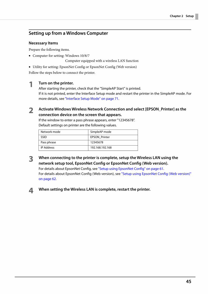
2 Activate Windows Wireless Network Connection and select [EPSON_Printer] as the connection device on the screen that appears.If the window to enter a pass phrase appears, enter "12345678”.Default settings on printer are the following values.
3 When connecting to the printer is complete, setup the Wireless LAN using the network setup tool, EpsonNet Config or EpsonNet Config (Web version).For details about EpsonNet Config, see "Setup using EpsonNet Config" on page 61.For details about EpsonNet Config (Web version), see "Setup using EpsonNet Config (Web version)"on page 62.
4 When setting the Wireless LAN is complete, restart the printer.
Network mode SimpleAP mode
SSID EPSON_Printer
Pass phrase 12345678
IP Address 192.168.192.168
46
Chapter 2 Setup
Bluetooth Interface
Pair the printer with your device using the Bluetooth function of the device or using other methods.Pairing the printer is also possible by using EPSON TM Bluetooth® Connector (Windows) or Epson TM Utility (iOS or Android).
Setting up from a Smart Device
Necessary ItemsPrepare the following items.• Device for setting: iOS or Android device• Utility for setting: Epson TM Utility for iOS/Android
Running Epson TM Utility for iOS/Android
1 Run the Epson TM Utility.
2 Set from “Bluetooth Setup Wizard” in the menu.Follow the on-screen instructions to complete the setup.
• If the host computer and the printer are not connected on a continuous basis but rather connected every time the printer starts printing, some time may be needed for the printer to actually start printing after the host computer commands printing. This pause is the time required for processing the connection between the host computer and the printer, and it depends on the conditions of the environment where used.
• If data transfer from an application of the host computer has already been completed, data might remain in the Bluetooth module internal buffer. As such data remaining in the buffer might be lost when the connection is cut off, use the status or similar functions to check that transmitted data has been completely printed before cutting off the wireless connection.
• For detailed information about EPSON TM Bluetooth® Connector, see the TM Bluetooth® Connector User’s Manual.
• The device name and passkey are editable with the TM-m50 Utility or Epson TM Utility.• The Bluetooth security level has been set to "Middle" by default. For information on the Bluetooth
security settings, see "Interface Setup Mode" on page 71.
47
Chapter 2 Setup
Setting up from a Windows ComputerFollow the procedure below and make the settings.
1 Have a Bluetooth wireless technology compatible computer ready.Make sure you have installed TM Bluetooth® Connector.
2 Turn on the printer.
3 Start TM Bluetooth® Connector.
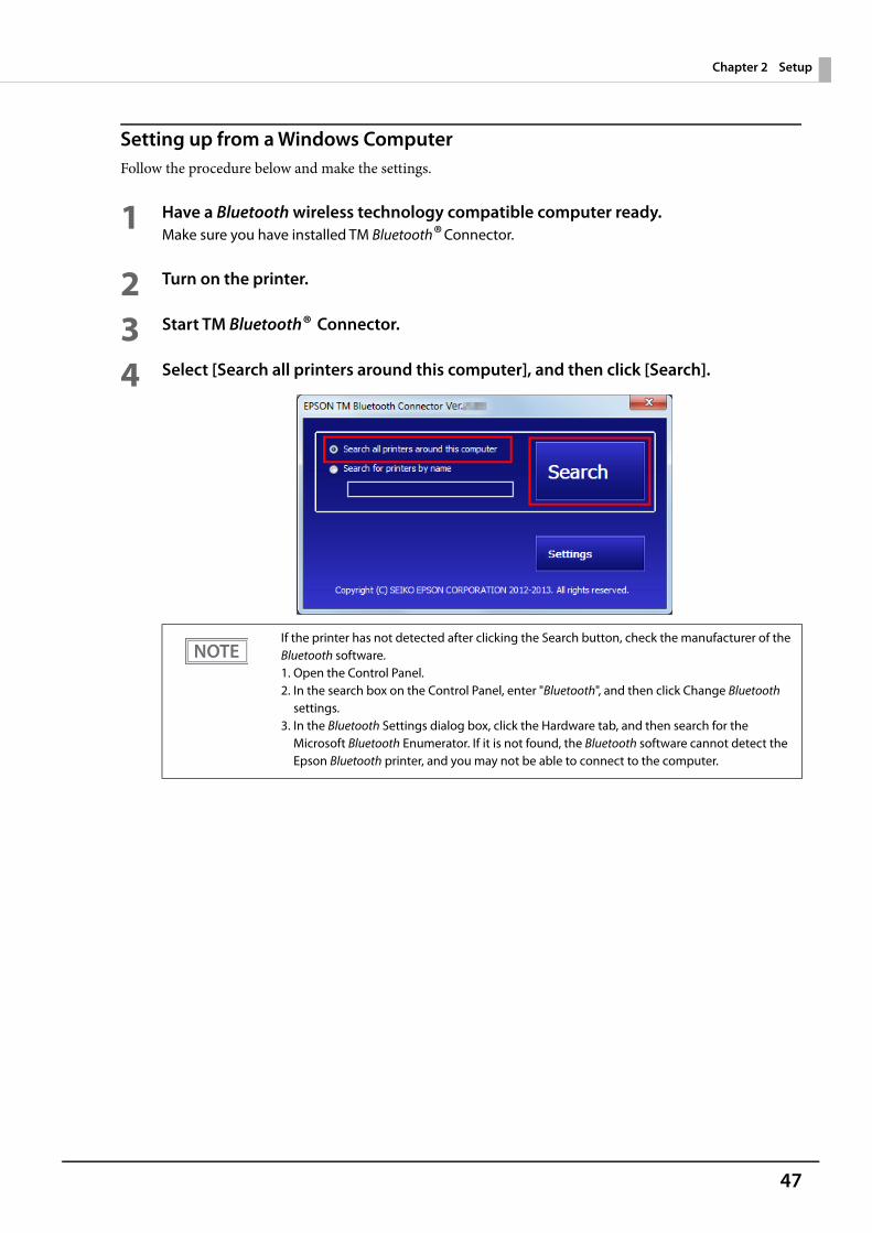
4 Select [Search all printers around this computer], and then click [Search].
If the printer has not detected after clicking the Search button, check the manufacturer of the Bluetooth software.1. Open the Control Panel.2. In the search box on the Control Panel, enter "Bluetooth", and then click Change Bluetooth
settings.3. In the Bluetooth Settings dialog box, click the Hardware tab, and then search for the
Microsoft Bluetooth Enumerator. If it is not found, the Bluetooth software cannot detect the Epson Bluetooth printer, and you may not be able to connect to the computer.
48
Chapter 2 Setup
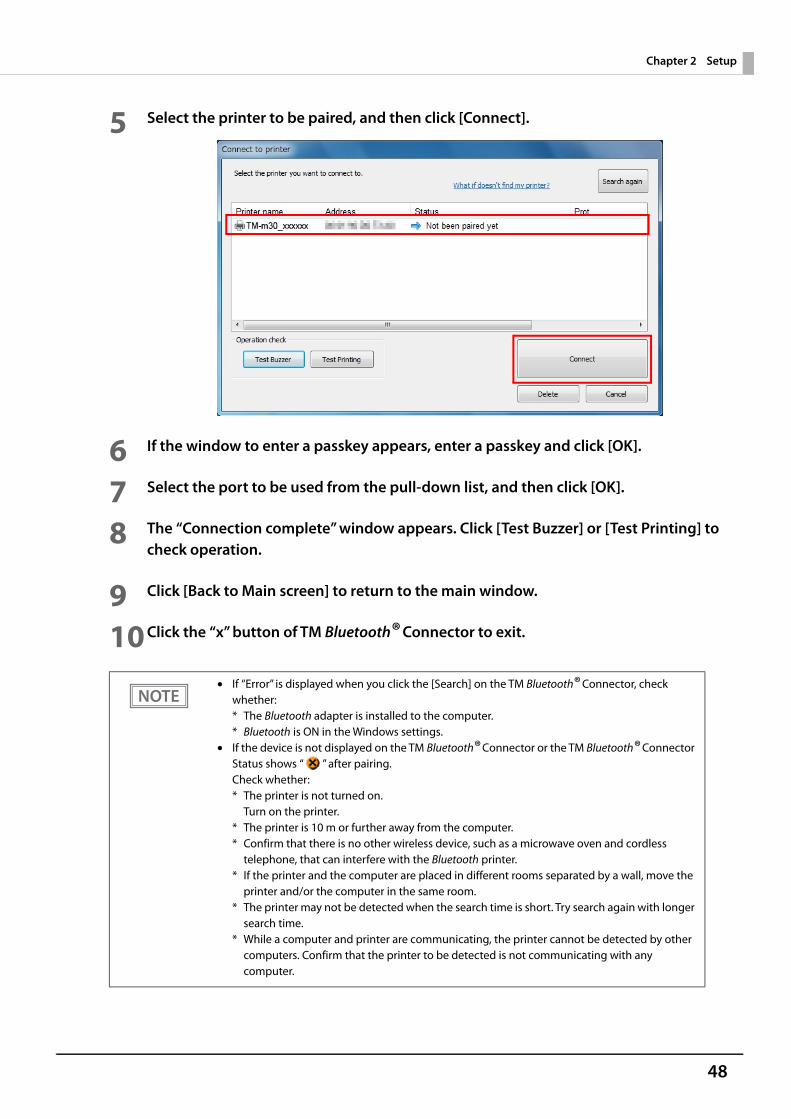
5 Select the printer to be paired, and then click [Connect].
6 If the window to enter a passkey appears, enter a passkey and click [OK].
7 Select the port to be used from the pull-down list, and then click [OK].
8 The “Connection complete” window appears. Click [Test Buzzer] or [Test Printing] to check operation.
9 Click [Back to Main screen] to return to the main window.
10Click the “x” button of TM Bluetooth® Connector to exit.
• If “Error” is displayed when you click the [Search] on the TM Bluetooth® Connector, check whether:* The Bluetooth adapter is installed to the computer.* Bluetooth is ON in the Windows settings.
• If the device is not displayed on the TM Bluetooth® Connector or the TM Bluetooth® Connector Status shows “ ” after pairing.Check whether:* The printer is not turned on.
Turn on the printer.* The printer is 10 m or further away from the computer.* Confirm that there is no other wireless device, such as a microwave oven and cordless
telephone, that can interfere with the Bluetooth printer.* If the printer and the computer are placed in different rooms separated by a wall, move the
printer and/or the computer in the same room.* The printer may not be detected when the search time is short. Try search again with longer
search time.* While a computer and printer are communicating, the printer cannot be detected by other
computers. Confirm that the printer to be detected is not communicating with any computer.
49
Chapter 2 Setup
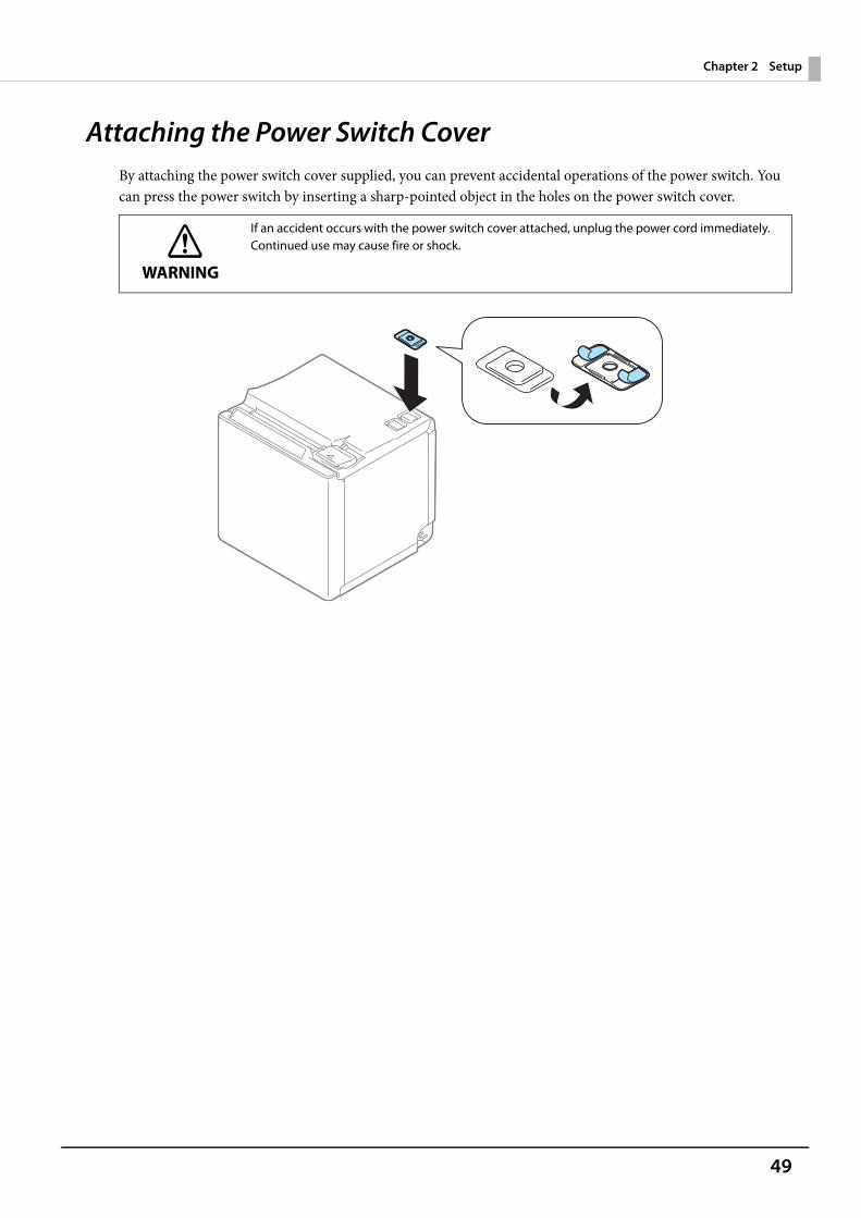
Attaching the Power Switch CoverBy attaching the power switch cover supplied, you can prevent accidental operations of the power switch. You can press the power switch by inserting a sharp-pointed object in the holes on the power switch cover.
WARNING
If an accident occurs with the power switch cover attached, unplug the power cord immediately. Continued use may cause fire or shock.
50
Chapter 2 Setup
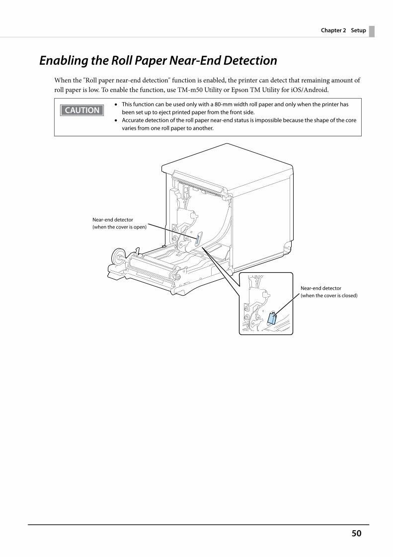
Enabling the Roll Paper Near-End DetectionWhen the "Roll paper near-end detection" function is enabled, the printer can detect that remaining amount of roll paper is low. To enable the function, use TM-m50 Utility or Epson TM Utility for iOS/Android.
• This function can be used only with a 80-mm width roll paper and only when the printer has been set up to eject printed paper from the front side.
• Accurate detection of the roll paper near-end status is impossible because the shape of the core varies from one roll paper to another.
Near-end detector(when the cover is open)
Near-end detector(when the cover is closed)
51
Chapter 3 Advanced Usage
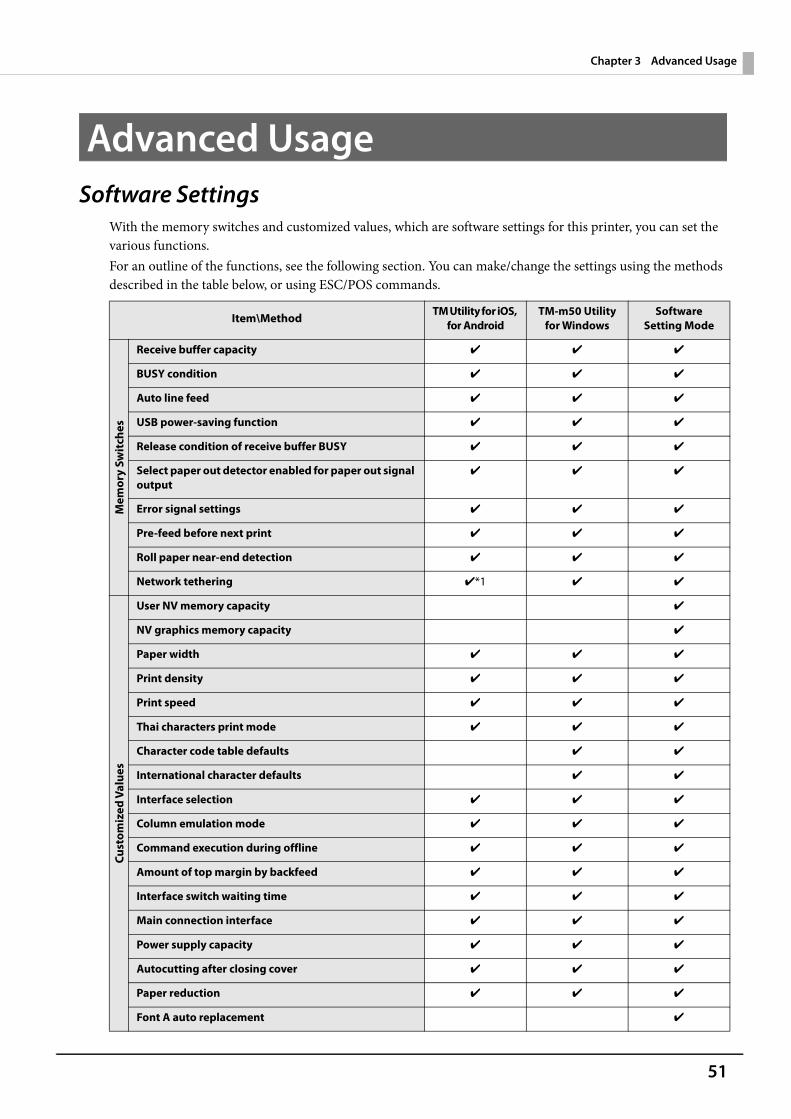
Advanced UsageSoftware Settings
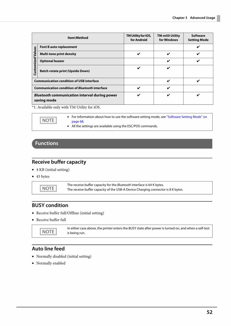
With the memory switches and customized values, which are software settings for this printer, you can set the various functions.For an outline of the functions, see the following section. You can make/change the settings using the methods described in the table below, or using ESC/POS commands.
Item\Method TM Utility for iOS, for Android
TM-m50 Utility for Windows
Software Setting Mode
Mem
ory
Swit
ches
Receive buffer capacity ✔ ✔ ✔
BUSY condition ✔ ✔ ✔
Auto line feed ✔ ✔ ✔
USB power-saving function ✔ ✔ ✔
Release condition of receive buffer BUSY ✔ ✔ ✔
Select paper out detector enabled for paper out signal output
✔ ✔ ✔
Error signal settings ✔ ✔ ✔
Pre-feed before next print ✔ ✔ ✔
Roll paper near-end detection ✔ ✔ ✔
Network tethering ✔*1 ✔ ✔
Cust
omiz
ed V
alue
s
User NV memory capacity ✔
NV graphics memory capacity ✔
Paper width ✔ ✔ ✔
Print density ✔ ✔ ✔
Print speed ✔ ✔ ✔
Thai characters print mode ✔ ✔ ✔
Character code table defaults ✔ ✔
International character defaults ✔ ✔
Interface selection ✔ ✔ ✔
Column emulation mode ✔ ✔ ✔
Command execution during offline ✔ ✔ ✔
Amount of top margin by backfeed ✔ ✔ ✔
Interface switch waiting time ✔ ✔ ✔
Main connection interface ✔ ✔ ✔
Power supply capacity ✔ ✔ ✔
Autocutting after closing cover ✔ ✔ ✔
Paper reduction ✔ ✔ ✔
Font A auto replacement ✔
52
Chapter 3 Advanced Usage
*1: Available only with TM Utility for iOS.
Functions
Receive buffer capacity• 4 KB (initial setting)• 45 bytes
BUSY condition• Receive buffer full/Offline (initial setting)• Receive buffer full
Auto line feed• Normally disabled (initial setting)• Normally enabled
Cust
omiz
ed V
alue
s Font B auto replacement ✔
Multi-tone print density ✔ ✔ ✔
Optional buzzer ✔ ✔
Batch rotate print (Upside Down)✔ ✔
Communication condition of USB interface ✔ ✔
Communication condition of Bluetooth interface ✔ ✔
Bluetooth communication interval during power saving mode
✔ ✔ ✔
• For information about how to use the software setting mode, see "Software Setting Mode" on page 68.
• All the settings are available using the ESC/POS commands.
The receive buffer capacity for the Bluetooth interface is 64 K bytes.The receive buffer capacity of the USB-A Device Charging connector is 8 K bytes.
In either case above, the printer enters the BUSY state after power is turned on, and when a self-test is being run.
Item\Method TM Utility for iOS, for Android
TM-m50 Utility for Windows
Software Setting Mode
53
Chapter 3 Advanced Usage
USB power-saving function• Disabled• Enabled (initial setting)
Release condition of receive buffer BUSY• Releases when the remaining receive buffer capacity becomes 256 bytes (initial setting)• Releases when the remaining receive buffer capacity becomes 138 bytes
Select paper out detector enabled for paper out signal output• Roll paper out detector (initial settings) • Disabled
Error signal settings• Enabled (initial setting)• Disabled
Pre-feed before next print• Disabled (initial setting)• Enabled
Roll paper near-end detection• Disabled (initial setting)• Enabled
Network tethering• Disabled (initial setting)• Enabled
The USB power-saving function is valid only when the USB interface communication condition is set to the vendor-defined class and the system configuration is set so that the USB driver can support the USB power-saving function.
This function is enabled only when Receive buffer capacity is set to 4 KB.
• When using this function, the top margin is approximately 10.5 mm.• This setting becomes invalid if you change the "Amount of top margin by backfeed" setting from
the initial setting (9.5 mm (no backfeed)).
54
Chapter 3 Advanced Usage
Paper width• 80 mm (initial setting)• 58 mm
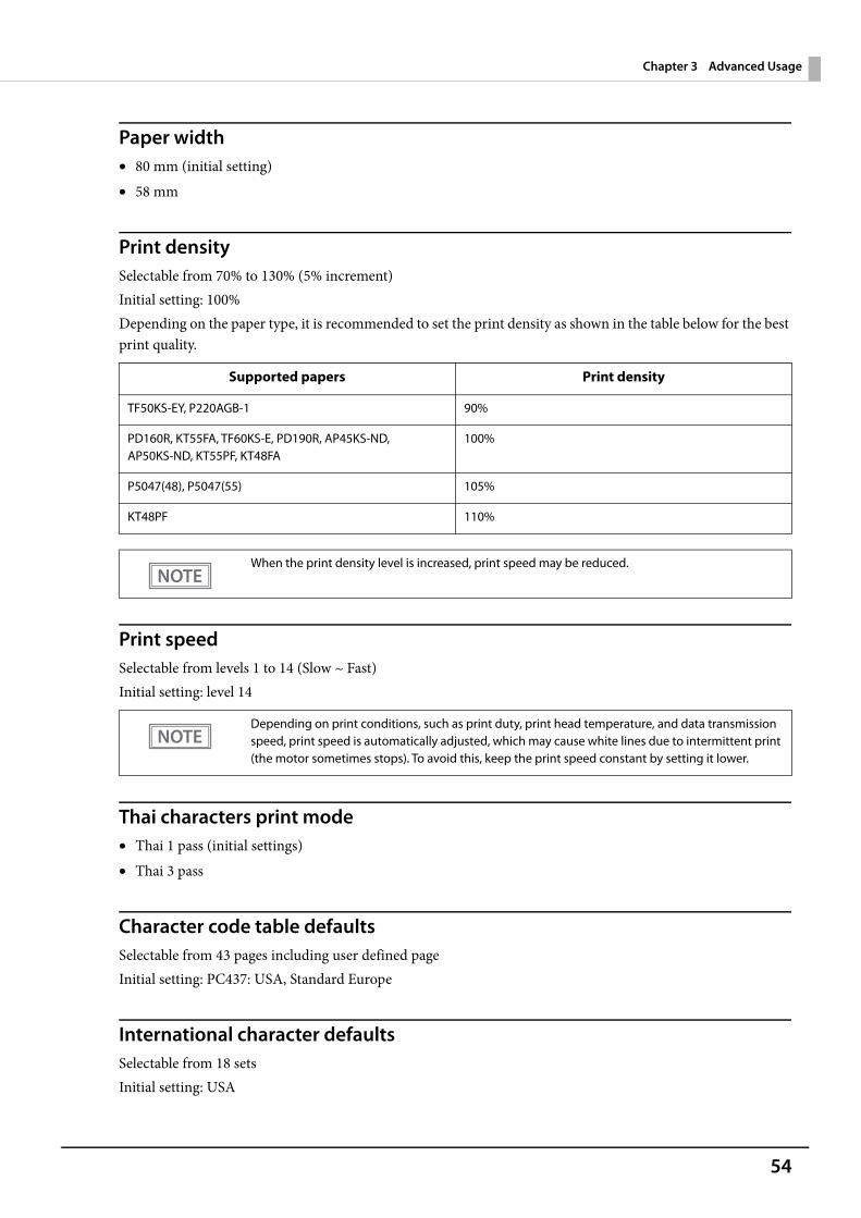
Print densitySelectable from 70% to 130% (5% increment)Initial setting: 100%Depending on the paper type, it is recommended to set the print density as shown in the table below for the best print quality.
Print speedSelectable from levels 1 to 14 (Slow ~ Fast)Initial setting: level 14
Thai characters print mode• Thai 1 pass (initial settings)• Thai 3 pass
Character code table defaultsSelectable from 43 pages including user defined pageInitial setting: PC437: USA, Standard Europe
International character defaultsSelectable from 18 sets Initial setting: USA
Supported papers Print density
TF50KS-EY, P220AGB-1 90%
PD160R, KT55FA, TF60KS-E, PD190R, AP45KS-ND, AP50KS-ND, KT55PF, KT48FA
100%
P5047(48), P5047(55) 105%
KT48PF 110%
When the print density level is increased, print speed may be reduced.
Depending on print conditions, such as print duty, print head temperature, and data transmission speed, print speed is automatically adjusted, which may cause white lines due to intermittent print (the motor sometimes stops). To avoid this, keep the print speed constant by setting it lower.
55
Chapter 3 Advanced Usage
Interface selection• Bluetooth only (only for Bluetooth capable models)• Serial interface only (only for serial models)• Standard USB only• Ethernet/Wi-Fi only• USB-A - Device Charging only• Enable all the interfaces (initial setting)• Enable all the interfaces except for Bluetooth (only for Bluetooth capable models)
Column emulation mode• 42/30 characters mode (standard mode) (initial setting)• 48/36 characters mode
Command execution during offline• Enabled (initial settings) • Disabled
Amount of top margin by backfeed• 2.0 mm• 9.5 mm (no backfeed) (initial settings)
Interface switch waiting timeSelect from 1 to 10 seconds (in intervals of 1 second)1 second (initial setting)
If you want to connect a tablet and the printer via Bluetooth while charging the tablet through the USB connector (USB-A - Device Charging), select “Bluetooth only”.
• When using the backfeed function with the printer that has been set up to eject paper from the top side, remove any paper ejected from the ejection slot before starting printing.
• Disable the automatic top logo setting when enabling backfeed.• Even if the "backfeed" has been enabled, it is not performed during the self-test.• If setting a top margin of 5 mm {0.2"} or less, confirm that no errors occur in your environment of
usage. Usage in a hot and humid environment or usage of paper that curls easily may increase the risk of paper jams.
• When the paper is fed backward, the paper may get wrinkled or smeared due to a slack in the roll. It is recommended to use thermal paper that has high resistance to abrasion.
• Make sure to feed the paper by at least 20 mm before moving the auto cutter. It the paper feed length is not enough, it may cause a paper jam.
You can specify values in 0.5 mm steps if you use TM-m50 Utility or TM Utility for iOS/Android.
56
Chapter 3 Advanced Usage
Main connection interface• Auto (interface that receives data first) (initial setting)• Serial (only for serial models)• USB• Bluetooth (only for Bluetooth capable models)• Ethernet/Wi-Fi• No main connection I/F
Power supply capacity (only for serial models)1 to 3 (lowest to highest capacity)Initial setting: 3
Autocutting after closing cover• Cuts (initial setting)• Does not cut
Paper reduction
Extra upper space reduction• Disabled (initial setting)• Enabled
Extra lower space reduction• Disabled (initial setting)• Enabled
Line space reduction rate• Not reduced (initial setting)• 25%• 50%• 75%
• When using this printer with multiple interfaces, make sure the interface that is always connected to be set as the main connection.
• When using multiple interfaces, set the receive buffer capacity to 4 KB.• You cannot use wired LAN and wireless LAN at the same time.• When you do not use the Bluetooth function, set the Bluetooth security level to "Middle" or
"High" to prevent unauthorized access to the printer over Bluetooth. You can change the security level by using Epson TM Utility, TM-m50 Utility, or in the Interface Setup mode.
• The displayed items vary depending on the interface configuration.• For information about the function, see "Printing Using Multiple Interfaces" on page 29.
57
Chapter 3 Advanced Usage
Line feed reduction rate• Not reduced (initial setting)• 25%• 50%• 75%
Character height reduction• Not reduced (initial setting)• 25% reduction of inner spacing• 50% reduction of inner spacing• 75% reduction of inner spacing• 75% reduction of inner spacing and shrinking the character height
Barcode height reduction rate• Not reduced (initial setting)• 25%• 50%• 75%
Font A auto replacement• Does not replace (initial setting)• Font B• Font C
Font B auto replacement• Does not replace (initial setting)• Font A• Font C
Multi-tone print densitySelectable from 70% to 130% (5% increment)Initial setting: 100%
• No reduction is applied to blank dot lines that exist in a graphic data.• Reduced barcodes are not guaranteed to be correctly scanned. Make sure to check whether
they are properly read by a barcode reader that is actually used.
58
Chapter 3 Advanced Usage
Optional buzzer
Enables/disables• Disabled (initial setting)• Enabled
Buzzer frequency (Error)• Does not sound• Sounds 1 time• Sounds continuously (initial setting)
Sound pattern (Autocut)Selectable from Patterns A to EInitial setting: Pattern A
Buzzer frequency (Autocut)• Does not sound• Sounds 1 time (initial setting)
Sound pattern (Pulse 1)Selectable from Patterns A to EInitial setting: Pattern A
Buzzer frequency (Pulse 1)• Does not sound• Sounds 1 time (initial setting)
Sound pattern (Pulse 2)Selectable from Patterns A to EInitial setting: Pattern B
Buzzer frequency (Pulse 2)• Does not sound• Sounds 1 time (initial setting)
Batch rotate print (Upside Down)• Disabled (initial setting)• Enabled
• For information about how to connect the optional external buzzer, see "Connecting the Optional External Buzzer" on page 37.
• When the optional external buzzer is enabled, a cash drawer cannot be used. Be sure to disable it when you use a cash drawer.
59
Chapter 3 Advanced Usage
Communication condition of USB interface
Class• USB printer class (initial setting)• USB vendor-defined class
Communication condition of Bluetooth interface• Device name (initial setting: TM-m50_xxxxxx)• Passkey (initial setting: 0000)• Security (initial setting: Low)• Auto Re-Connect with iOS device (initial setting: Enabled)
Bluetooth communication interval during power saving mode• Level 1 (Standard) (Initial setting)• Level 2 (Short)
The device name is initially set to TM-m50_xxxxxx.(xxxxxx refers to the last 6 digits of the serial number labeled on the back of your printer.)
By changing the setting to "Level 2 (Short)," you can shorten the time until printing begins or the time until information is shown on the customer display connected to the printer.However, because the communication frequency increases, the power consumption of the printer and the host also increases.Also, depending on the host, this setting may not be enabled, and the host-specified communication interval may be used.
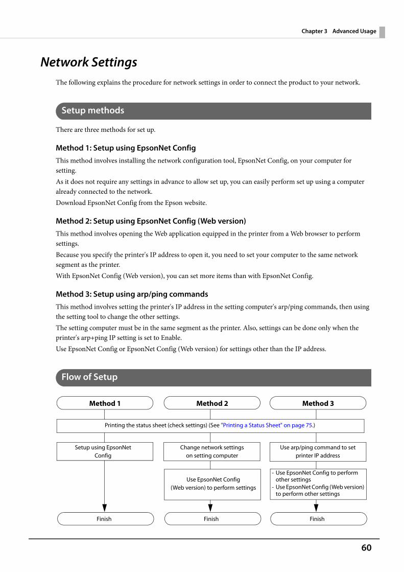
60
Chapter 3 Advanced Usage
Network SettingsThe following explains the procedure for network settings in order to connect the product to your network.
Setup methods
There are three methods for set up.
Method 1: Setup using EpsonNet ConfigThis method involves installing the network configuration tool, EpsonNet Config, on your computer for setting.As it does not require any settings in advance to allow set up, you can easily perform set up using a computer already connected to the network.Download EpsonNet Config from the Epson website.
Method 2: Setup using EpsonNet Config (Web version)This method involves opening the Web application equipped in the printer from a Web browser to perform settings.Because you specify the printer's IP address to open it, you need to set your computer to the same network segment as the printer.With EpsonNet Config (Web version), you can set more items than with EpsonNet Config.
Method 3: Setup using arp/ping commandsThis method involves setting the printer's IP address in the setting computer's arp/ping commands, then using the setting tool to change the other settings.The setting computer must be in the same segment as the printer. Also, settings can be done only when the printer's arp+ping IP setting is set to Enable.Use EpsonNet Config or EpsonNet Config (Web version) for settings other than the IP address.
Flow of Setup
Change network settings on setting computer
Setup using EpsonNet Config
Printing the status sheet (check settings) (See "Printing a Status Sheet" on page 75.)
Method 1 Method 2 Method 3
- Use EpsonNet Config to perform other settings
- Use EpsonNet Config (Web version) to perform other settings
Use arp/ping command to set printer IP address
Finish Finish Finish
Use EpsonNet Config(Web version) to perform settings
61
Chapter 3 Advanced Usage
Setup using EpsonNet Config
Execute EpsonNet Config, select the target printer from the displayed device list, then check and change the settings.If the printer is still set to factory defaults, the printer's MAC address is listed up, even if the computer does not have the same network address.
1 Connect the printer to the same network as the computer where you installed EpsonNet Config.
2 Start up EpsonNet Config.The tool automatically detects printers connected to the network and displays a list.It may take up to a minute for the printer to be displayed in the list.If it is not displayed, check that [Filter] is set to "(All)" or "Network-connected devices", then click [Refresh]. Or, select [Tools], then [Option], and check the settings of [Search Parameters].
3 Select the target printer, then click [Configuration].If you cannot determine the target printer from the product name or the IP address, use the MAC address. You can check the printer's MAC address on the status sheet.
4 Change the printer's settings based on the network setting information you receivedfrom the network administrator.Select an item from the menu and change the setting.
5 Once you set the necessary items, click [Transmit].The changed contents are sent to the printer and the printer settings are changed.
• The initial setting uses an IP address for the printer provided by a DHCP server. Since you cannot complete setup if there are conflicting IP addresses on the network, make sure that there are no other devices on the network that conflict with the IP address provided by the DHCP server. If a DHCP server is not available, a fixed IP address (192.168.192.168) is set approximately one minute after turning on the printer. Also, if the Ethernet cable is not connected, connect the Ethernet cable and then run this process.
• When DHCP is enabled, the provided IP address is printed automatically. However, if the Ethernet cable is not connected, and the Wireless LAN unit is not installed, printing is not performed.
For details about EpsonNet Config, see the manual (operation guide) installed together with the tool or the online help.
62
Chapter 3 Advanced Usage
Setup using EpsonNet Config (Web version)
Follow the steps below to start up EpsonNet Config (Web version), and check or change the settings.
1 Connect the setting computer and the printer to the same network.
2 Perform network settings on the computer so that it is in the same segment as theprinter's IP address.
Subnet mask: Same subnet mask as the printerIP address: Same segment (same network address) as the printer, different host address
Check the values set in the printer on the status sheet.
3 Start up your Web browser and input the printer's IP address into the address field.E.g.) http://192.168.192.168
• When setting up using the EpsonNet Config (Web version), you need to set the network settings for the device to the same network segment as the printer you want to connect to.
• The initial setting uses an IP address for the printer provided by a DHCP server. Since you cannot complete setup if there are conflicting IP addresses on the network, make sure that there are no other devices on the network that conflict with the IP address provided by the DHCP server. If a DHCP server is not available, a fixed IP address (192.168.192.168) is set approximately one minute after turning on the printer. Also, if the Ethernet cable is not connected, connect the Ethernet cable and then run this process.
• When DHCP is enabled, the provided IP address is printed automatically. However, if the Ethernet cable is not connected, and the Wireless LAN unit is not installed, printing is not performed.
E.g.) Printer Setting computer
Subnet mask 255.255.255.0 255.255.255.0
IP address 192.168.192.168 192.168.192.2
Under initial settings, when you access EpsonNet Config (Web version) from your browser, an authentication warning message may be displayed.
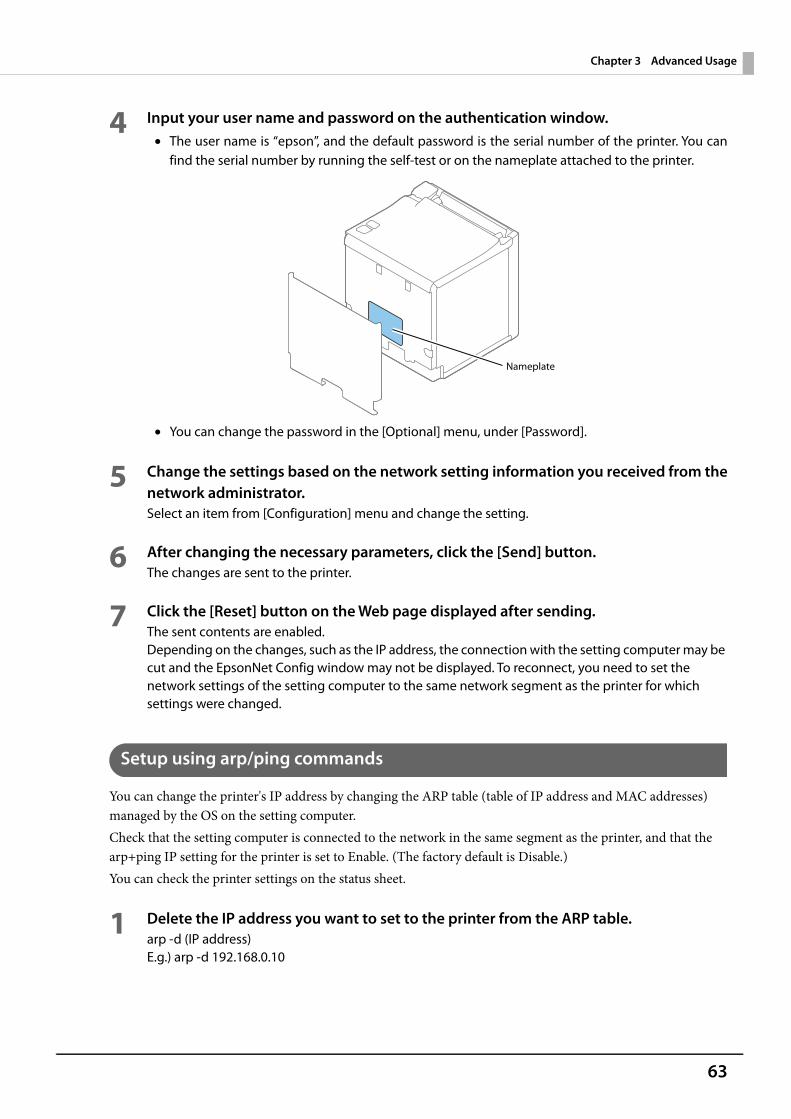
63
Chapter 3 Advanced Usage
4 Input your user name and password on the authentication window.• The user name is “epson”, and the default password is the serial number of the printer. You can
find the serial number by running the self-test or on the nameplate attached to the printer.
• You can change the password in the [Optional] menu, under [Password].
5 Change the settings based on the network setting information you received from thenetwork administrator.Select an item from [Configuration] menu and change the setting.
6 After changing the necessary parameters, click the [Send] button.The changes are sent to the printer.
7 Click the [Reset] button on the Web page displayed after sending.The sent contents are enabled.Depending on the changes, such as the IP address, the connection with the setting computer may be cut and the EpsonNet Config window may not be displayed. To reconnect, you need to set the network settings of the setting computer to the same network segment as the printer for which settings were changed.
Setup using arp/ping commands
You can change the printer's IP address by changing the ARP table (table of IP address and MAC addresses) managed by the OS on the setting computer.Check that the setting computer is connected to the network in the same segment as the printer, and that the arp+ping IP setting for the printer is set to Enable. (The factory default is Disable.)You can check the printer settings on the status sheet.
1 Delete the IP address you want to set to the printer from the ARP table.arp -d (IP address)E.g.) arp -d 192.168.0.10
Nameplate
64
Chapter 3 Advanced Usage
2 Add the printer's MAC address and the IP address you want to set to the ARP table.arp -s (IP address) (MAC address)E.g.) arp -s 192.168.0.10 00-26-AB-7B-00-00
3 Execute the ping command and enable settings.ping (IP address you want to set)E.g.) ping 192.168.0.10When a message like "Reply From 192.168.0.10: Bytes=32 Time < 10 ms TTL=255" is displayed, the IP address setting is complete.
Use EpsonNet Config or EpsonNet Config (Web version) for settings other than the IP address.
MAC Address Confirmation
You can check the printer's MAC address using the following procedures.• Printing the status sheet (MAC Address)• A printer self-test (Only supported on Ethernet. For wireless, see the status sheet.)• Using EpsonNet Config to confirm• Using a Web browser to confirm (EpsonNet Config (Web version) function)
You can check the MAC address for network tethering using the following method.• Printing the status sheet (MAC Address2)
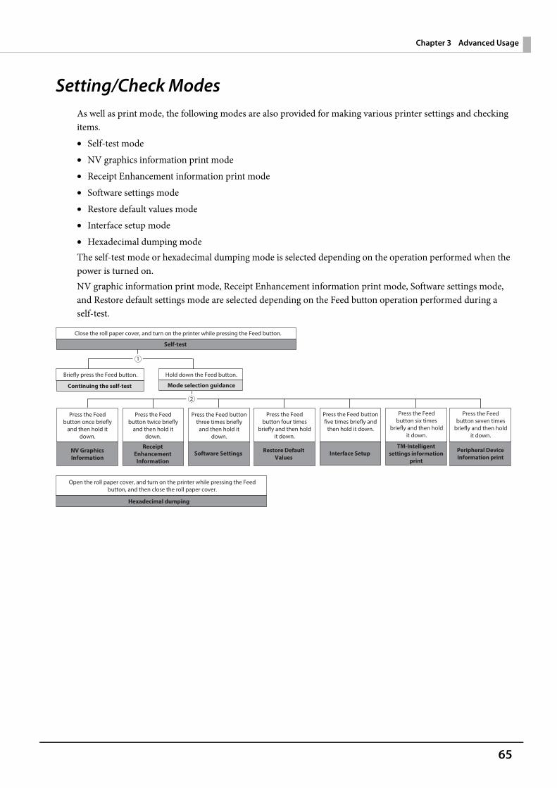
65
Chapter 3 Advanced Usage
Setting/Check ModesAs well as print mode, the following modes are also provided for making various printer settings and checking items.• Self-test mode• NV graphics information print mode• Receipt Enhancement information print mode• Software settings mode• Restore default values mode• Interface setup mode• Hexadecimal dumping modeThe self-test mode or hexadecimal dumping mode is selected depending on the operation performed when the power is turned on.NV graphic information print mode, Receipt Enhancement information print mode, Software settings mode, and Restore default settings mode are selected depending on the Feed button operation performed during a self-test.
Close the roll paper cover, and turn on the printer while pressing the Feed button.
Self-test
Briefly press the Feed button. Hold down the Feed button.
Open the roll paper cover, and turn on the printer while pressing the Feed button, and then close the roll paper cover.
Continuing the self-test Mode selection guidance
Hexadecimal dumping
Press the Feed button once briefly
and then hold it down.
NV Graphics Information
Press the Feed button twice briefly
and then hold it down.
Receipt Enhancement Information
Press the Feed button three times briefly
and then hold it down.
Software Settings
Press the Feed button four times
briefly and then hold it down.
Restore Default Values
Press the Feed button five times briefly and
then hold it down.
Interface Setup
Press the Feed button six times
briefly and then hold it down.
TM-Intelligent settings information
Press the Feed button seven times
briefly and then hold it down.
Peripheral Device Information print
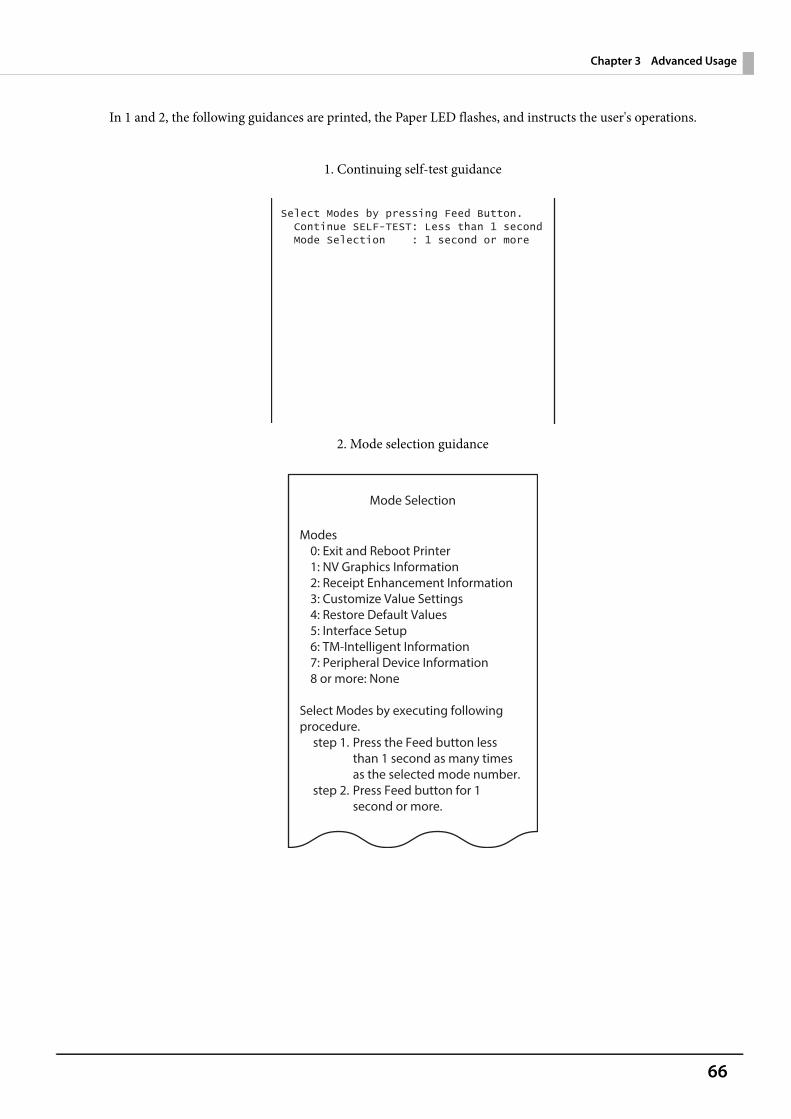
66
Chapter 3 Advanced Usage
In 1 and 2, the following guidances are printed, the Paper LED flashes, and instructs the user's operations.
1. Continuing self-test guidance
2. Mode selection guidance
Mode Selection
Modes0: Exit and Reboot Printer1: NV Graphics Information2: Receipt Enhancement Information3: Customize Value Settings4: Restore Default Values5: Interface Setup6: TM-Intelligent Information7: Peripheral Device Information8 or more: None
Select Modes by executing following procedure.
step 1. Press the Feed button less than 1 second as many times as the selected mode number.
step 2. Press Feed button for 1 second or more.
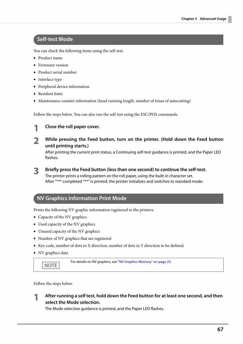
67
Chapter 3 Advanced Usage
Self-test Mode
You can check the following items using the self-test.• Product name• Firmware version• Product serial number• Interface type• Peripheral device information• Resident fonts• Maintenance counter information (head running length, number of times of autocutting)
Follow the steps below. You can also run the self-test using the ESC/POS commands.
1 Close the roll paper cover.
2 While pressing the Feed button, turn on the printer. (Hold down the Feed buttonuntil printing starts.)After printing the current print status, a Continuing self-test guidance is printed, and the Paper LED flashes.
3 Briefly press the Feed button (less than one second) to continue the self-test.The printer prints a rolling pattern on the roll paper, using the built-in character set.After “*** completed ***” is printed, the printer initializes and switches to standard mode.
NV Graphics Information Print Mode
Prints the following NV graphic information registered to the printers.• Capacity of the NV graphics• Used capacity of the NV graphics• Unused capacity of the NV graphics• Number of NV graphics that are registered• Key code, number of dots in X direction, number of dots in Y direction to be defined.• NV graphics data
Follow the steps below.
1 After running a self test, hold down the Feed button for at least one second, and then select the Mode selection.The Mode selection guidance is printed, and the Paper LED flashes.
For details on NV graphics, see "NV Graphics Memory" on page 25.
68
Chapter 3 Advanced Usage
2 After briefly (less than one second) pressing the Feed button once, hold it down for atleast one second, to print the NV graphics information.After information printing, the Mode selection guidance is printed again.
3 To finish, turn off the power, or select “Exit and Reboot Printer”.
Receipt Enhancement Information Print Mode
You can check the following items using the R/E information mode:• Automatic top logo setting• Automatic bottom logo setting• Extended settings for automatic top/bottom logo
Follow the steps below.
1 After running a self test, hold down the Feed button for at least one second, and then select the Mode selection.The Mode selection guidance is printed, and the Paper LED flashes.
2 After briefly (less than one second) pressing the Feed button twice, hold it down forat least one second, to print the R/E information.After information printing, the Mode selection guidance is printed again.
3 To finish, turn off the power, or select “Exit and Reboot Printer”.
Software Setting Mode
Set the printer's memory switches and customized values.• Print Density• Automatic Paper Reduction• Enable/Disable Auto Paper Feed&Cut at cover close• Paper Width• Thai characters print mode• Selection of character set• Embedded Font Replacement• Communication condition of USB Interface• Print Speed• NV Memory Capacity• Command execution during offline• Amount of top margin by backfeed• Buzzer Control
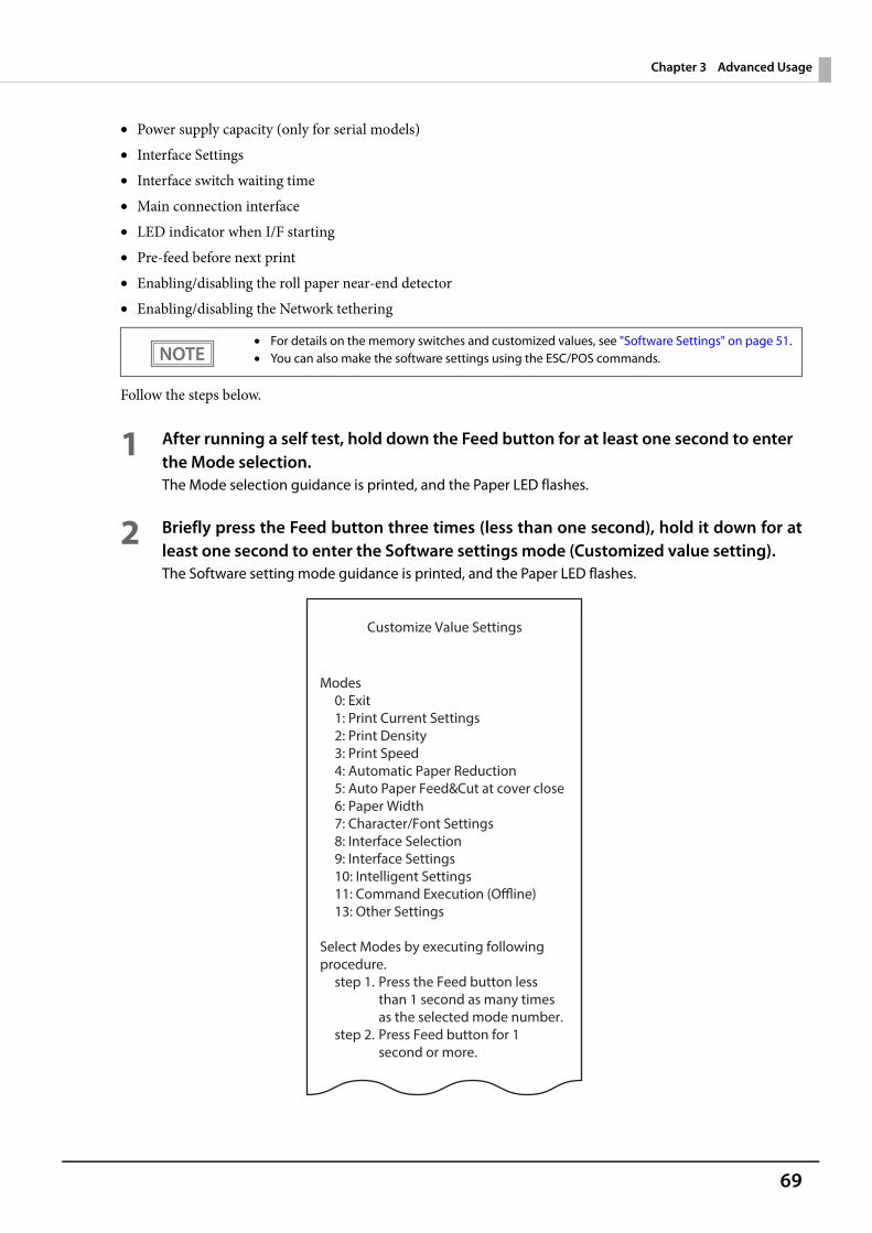
69
Chapter 3 Advanced Usage
• Power supply capacity (only for serial models)• Interface Settings• Interface switch waiting time• Main connection interface• LED indicator when I/F starting• Pre-feed before next print• Enabling/disabling the roll paper near-end detector• Enabling/disabling the Network tethering
Follow the steps below.
1 After running a self test, hold down the Feed button for at least one second to enter the Mode selection.The Mode selection guidance is printed, and the Paper LED flashes.
2 Briefly press the Feed button three times (less than one second), hold it down for atleast one second to enter the Software settings mode (Customized value setting).The Software setting mode guidance is printed, and the Paper LED flashes.
• For details on the memory switches and customized values, see "Software Settings" on page 51.• You can also make the software settings using the ESC/POS commands.
Customize Value Settings
Modes0: Exit1: Print Current Settings2: Print Density3: Print Speed4: Automatic Paper Reduction5: Auto Paper Feed&Cut at cover close6: Paper Width7: Character/Font Settings8: Interface Selection9: Interface Settings10: Intelligent Settings11: Command Execution (Offline)13: Other Settings
Select Modes by executing following procedure.
step 1. Press the Feed button less than 1 second as many times as the selected mode number.
step 2. Press Feed button for 1 second or more.
70
Chapter 3 Advanced Usage
3 After briefly pressing the Feed button (less than one second) for the number of timesshown in the print result, hold down the button for more than one second to selectthe setting items.The setting selected as the setting item, the current settings and initial settings are printed.Depending on the setting item, you may need to continue selecting the setting item before the settings are printed.For details on setting items, see "Software Settings" on page 51.
4 Select a setting by briefly pressing the Feed button (less than one second) for thenumber of times applicable to the setting, and then hold down the button for morethan one second to confirm your selection.After saving the settings, the Software setting mode guidance is printed, and the Paper LED flashes.
5 To close Software setting mode, turn off the printer, or select “Exit” to return to Modeselection guidance, and then select “Exit and Reboot Printer”.
Restore Default Values Mode
In Restore default values mode, following values saved on NV Memory will be set back to initial settings. When any error occurs, you can use to specify the reason.
• Memory switch• Customized Value• Communication Condition of USB Interface• Status• Character types• Accessories• Barcode• Two-Dimensional Symbol• Print Position• Logo Setting• TM-Intelligent function settings
Follow the steps below.
1 After running a self test, hold down the Feed button for at least one second to enter the Mode selection.The Mode selection guidance is printed, and the Paper LED flashes.
• To select 0 as the item number, hold down the Feed button until printing starts.• If the button is pressed a number of times that is not displayed by the Setup guidance, the
operation is invalid and the same guidance is printed.
71
Chapter 3 Advanced Usage
2 Briefly press the Feed button four times (less than one second), hold it down for atleast one second to enter the Restore Default Values.The guidance is printed.
3 Briefly press the Feed button once (less than one second), hold it down for at leastone second. (Hold down the Feed button until the message of restore completion isprinted.)
Interface Setup Mode
Use this mode to setup the interface and other settings.
Follow the steps below.
1 After running a self test, hold down the Feed button for at least one second to enter the Mode selection.The Mode selection guidance is printed, and the Paper LED flashes.
2 Briefly press the Feed button five times (less than one second), hold it down for atleast one second to enter the Interface Setup mode.The guidance is printed.
3 After briefly pressing the Feed button (less than one second) for the number of timesshown in the print result, hold down the button for more than one second to selectthe setting items.
InitializeSelect [Wi-Fi & Ethernet Setup] or [Bluetooth Setup] and select [Initialize] to restore the communication settings to the factory default. The printer is reset and restarted.
SimpleAP mode (When using the Wireless LAN unit) When using the Wireless LAN unit, select [Wi-Fi & Ethernet Setup] and select [SimpleAP] to start in SimpleAP mode (the same as the factory default setting). The printer is reset and restarted, and it begins printing the "SimpleAP Start" information.Select this to quickly set up a network connection.
For information on the Quick connection function, see "Simple Setup for Wireless LAN" on page 27.
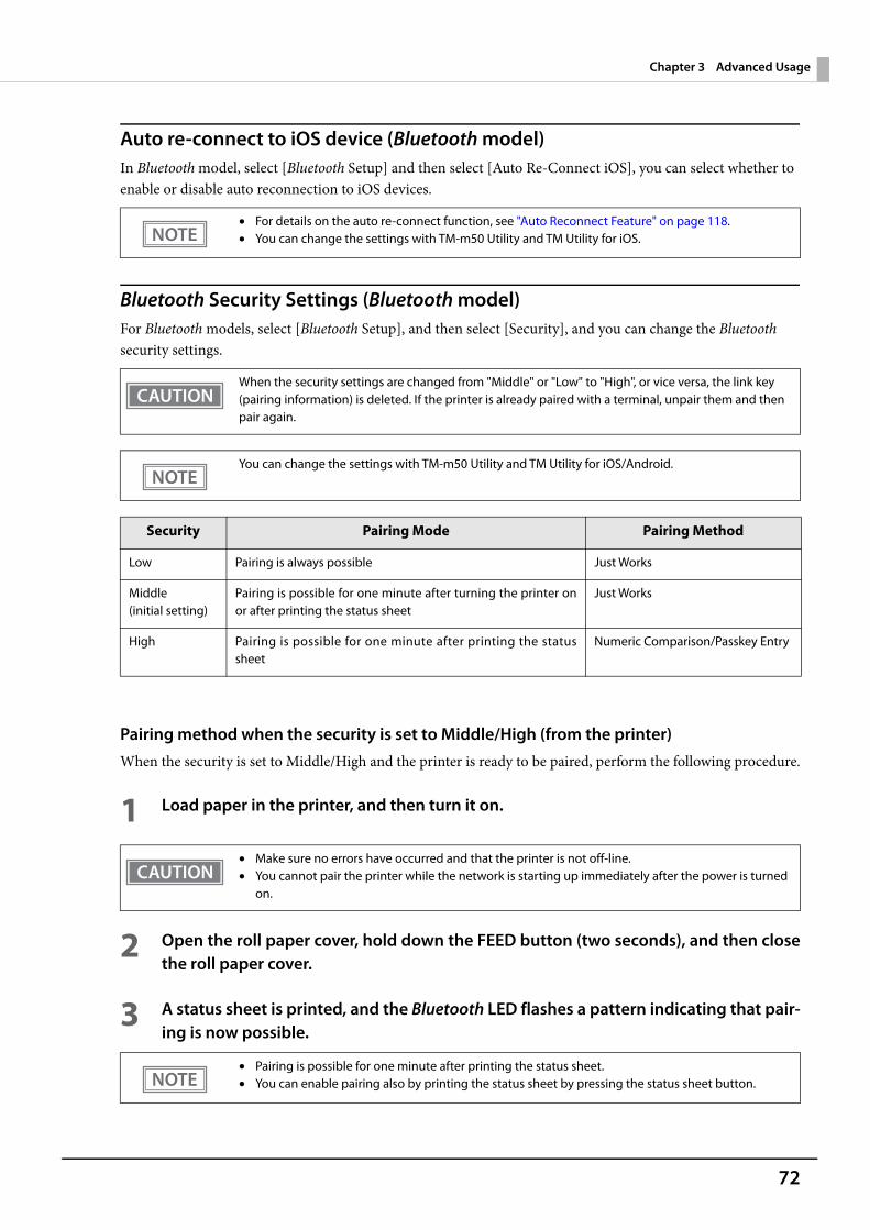
72
Chapter 3 Advanced Usage
Auto re-connect to iOS device (Bluetooth model)In Bluetooth model, select [Bluetooth Setup] and then select [Auto Re-Connect iOS], you can select whether to enable or disable auto reconnection to iOS devices.
Bluetooth Security Settings (Bluetooth model)For Bluetooth models, select [Bluetooth Setup], and then select [Security], and you can change the Bluetooth security settings.
Pairing method when the security is set to Middle/High (from the printer)When the security is set to Middle/High and the printer is ready to be paired, perform the following procedure.
1 Load paper in the printer, and then turn it on.
2 Open the roll paper cover, hold down the FEED button (two seconds), and then closethe roll paper cover.
3 A status sheet is printed, and the Bluetooth LED flashes a pattern indicating that pair-ing is now possible.
• For details on the auto re-connect function, see "Auto Reconnect Feature" on page 118.• You can change the settings with TM-m50 Utility and TM Utility for iOS.
When the security settings are changed from "Middle" or "Low" to "High", or vice versa, the link key (pairing information) is deleted. If the printer is already paired with a terminal, unpair them and then pair again.
You can change the settings with TM-m50 Utility and TM Utility for iOS/Android.
Security Pairing Mode Pairing Method
Low Pairing is always possible Just Works
Middle (initial setting)
Pairing is possible for one minute after turning the printer onor after printing the status sheet
Just Works
High Pairing is possible for one minute after printing the statussheet
Numeric Comparison/Passkey Entry
• Make sure no errors have occurred and that the printer is not off-line.• You cannot pair the printer while the network is starting up immediately after the power is turned
on.
• Pairing is possible for one minute after printing the status sheet.• You can enable pairing also by printing the status sheet by pressing the status sheet button.
73
Chapter 3 Advanced Usage
Pairing method when the security is set to High (from the host)When the security is set to High and the printer is ready to be paired, perform the following procedure.
1 Search for the printer on the Bluetooth settings screen on the host device.
2 Select the printer you want to pair with.The printer prints the Passkey.
3 Check that the printed Passkey and the Passkey displayed on the host device match,and then select "Pairing" on the host device.
TM-Intelligent Settings Information Print Mode
This function allows you to print TM-Intelligent setting information currently registered in the printer.
Follow the steps below.
1 After running a self-test, hold down the Feed button for at least one second to enterthe Mode selection.The Mode selection guidance is printed, and the Paper LED flashes.
2 Briefly press the Feed button six times (less than one second), hold it down for atleast one second to print the TM-Intelligent setting information.After information printing, the Mode selection guidance is printed again.
3 To finish, turn off the power, or select “Exit and Reboot Printer”.
Peripheral Device Information Print Mode
This function allows you to print information for the device currently connected to the printer.• Customer display information• Wi-Fi adapter information• Bluetooth adapter information• Handheld scanner information
Follow the steps below.
1 After running a self-test, hold down the Feed button for at least one second to enterthe Mode selection.The Mode selection guidance is printed, and the Paper LED flashes.
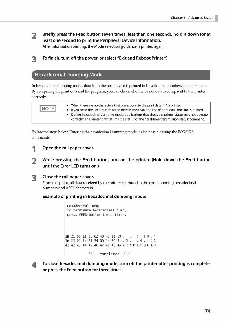
74
Chapter 3 Advanced Usage
2 Briefly press the Feed button seven times (less than one second), hold it down for atleast one second to print the Peripheral Device Information.After information printing, the Mode selection guidance is printed again.
3 To finish, turn off the power, or select “Exit and Reboot Printer”.
Hexadecimal Dumping Mode
In hexadecimal dumping mode, data from the host device is printed in hexadecimal numbers and characters. By comparing the print outs and the program, you can check whether or not data is being sent to the printer correctly.
Follow the steps below. Entering the hexadecimal dumping mode is also possible using the ESC/POS commands.
1 Open the roll paper cover.
2 While pressing the Feed button, turn on the printer. (Hold down the Feed buttonuntil the Error LED turns on.)
3 Close the roll paper cover.From this point, all data received by the printer is printed in the corresponding hexadecimal numbers and ASCII characters.
Example of printing in hexadecimal dumping mode:
4 To close hexadecimal dumping mode, turn off the printer after printing is complete,or press the Feed button for three times.
• When there are no characters that correspond to the print data, “ . ” is printed.• If you press the Feed button when there is less than one line of print data, one line is printed.• During hexadecimal dumping mode, applications that check the printer status may not operate
correctly. The printer only returns the status for the “Real-time transmission status” command.
75
Chapter 3 Advanced Usage
Printing a Status SheetFollow the steps below to check the interface settings.
Using the Status Sheet Button
1 Check that the printer is turned on.Make sure the roll paper cover is closed.
2 If there is a bottom cover, remove the cover.See "Removing the Covers" on page 99 for details on removing the bottom cover.
3 Hold down the status sheet button for at least three seconds.The status sheet is printed. After printing, the printer returns to the standard mode.
Using the Feed button
1 Check that the printer is on.
2 Open the roll paper cover.
3 Hold down the Feed button for at least one second.
4 Close the roll paper cover.The status sheet is printed. After printing, the printer returns to the standard mode.
You cannot print after turning on the power while the Power LED is flashing.
• After the status sheet is printed, only the print settings of the mainly connected interface are retained. For the mainly connected interface, see "Printing Using Multiple Interfaces" on page 29.
• Ethernet and Wi-Fi status sheets are not printed while the printing communication protocol is being established. They will be printed after the connection is cut off (including being cut due to a time out).
• The Bluetooth status sheet is not printed if status sheet printing is performed under the following conditions.* Bluetooth is connected when the Bluetooth security is set to "Medium" or "High"* An error occurs when the Bluetooth security is set to "Medium" or "High"* Time between when a pairing request is received and Passkey printing starts when the Bluetooth security is set to "High"
• "(none)" is printed for the "Connected Peripheral" if no peripherals are connected to the USB downstream port connector.
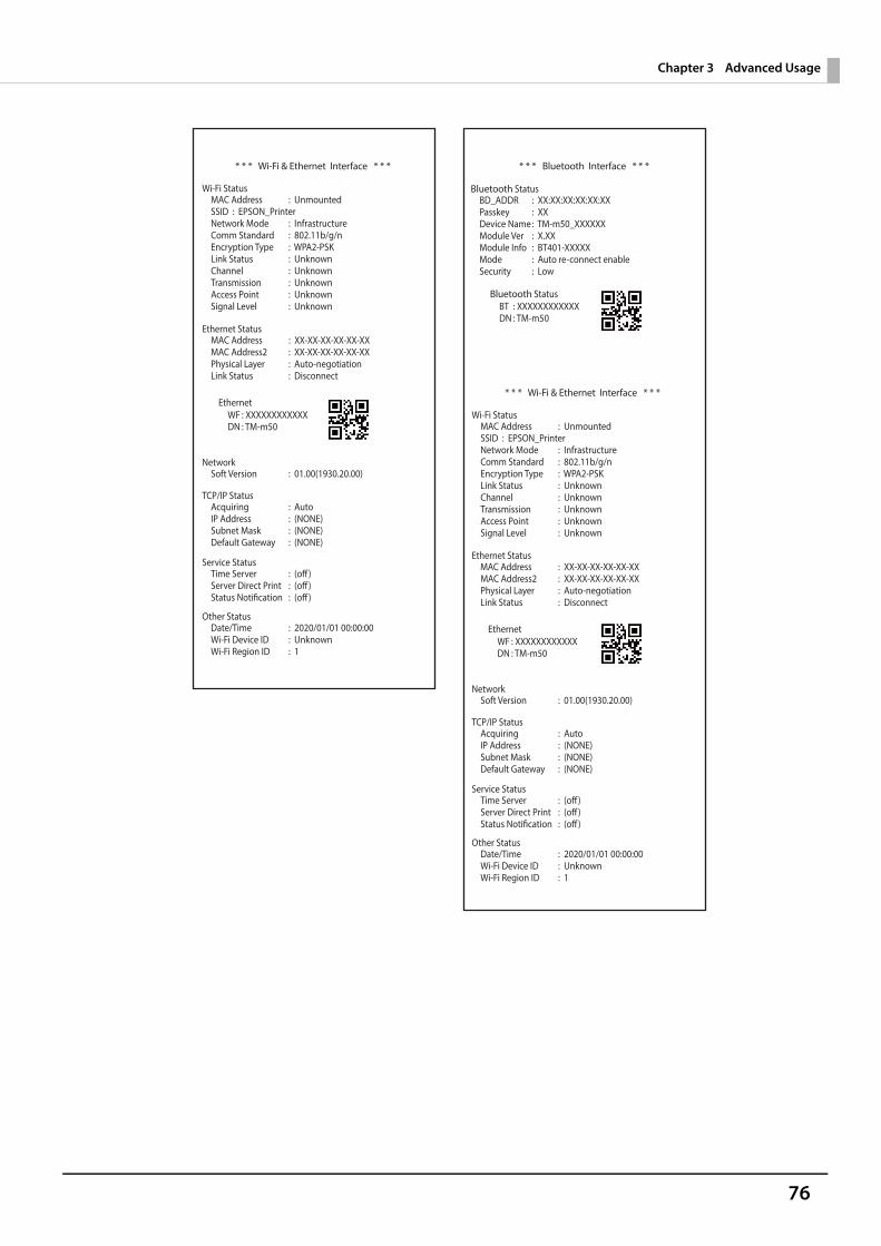
76
Chapter 3 Advanced Usage
* * * Wi-Fi & Ethernet Interface * * *
Wi-Fi StatusMAC AddressSSID : EPSON_PrinterNetwork ModeComm StandardEncryption TypeLink StatusChannelTransmissionAccess PointSignal Level
: Unmounted
: Infrastructure: 802.11b/g/n: WPA2-PSK: Unknown: Unknown: Unknown: Unknown: Unknown
Ethernet Status
MAC Address2Physical LayerLink Status
: XX-XX-XX-XX-XX-XX: Auto-negotiation: Disconnect
: XX-XX-XX-XX-XX-XXMAC Address
NetworkSoft Version : 01.00(1930.20.00)
TCP/IP StatusAcquiringIP AddressSubnet MaskDefault Gateway
: Auto: (NONE): (NONE): (NONE)
Service StatusTime ServerServer Direct PrintStatus Notification
: (off): (off): (off)
Other StatusDate/TimeWi-Fi Device IDWi-Fi Region ID
: 2020/01/01 00:00:00: Unknown: 1
: XXXXXXXXXXXX: TM-m50
WFDN
Ethernet* * * Wi-Fi & Ethernet Interface * * *
Wi-Fi StatusMAC AddressSSID : EPSON_PrinterNetwork ModeComm StandardEncryption TypeLink StatusChannelTransmissionAccess PointSignal Level
: Unmounted
: Infrastructure: 802.11b/g/n: WPA2-PSK: Unknown: Unknown: Unknown: Unknown: Unknown
Ethernet Status
MAC Address2Physical LayerLink Status
: XX-XX-XX-XX-XX-XX: Auto-negotiation: Disconnect
MAC Address : XX-XX-XX-XX-XX-XX
NetworkSoft Version : 01.00(1930.20.00)
TCP/IP StatusAcquiringIP AddressSubnet MaskDefault Gateway
: Auto: (NONE): (NONE): (NONE)
Service StatusTime ServerServer Direct PrintStatus Notification
: (off): (off): (off)
Other StatusDate/TimeWi-Fi Device IDWi-Fi Region ID
: 2020/01/01 00:00:00: Unknown: 1
: XXXXXXXXXXXX: TM-m50
WFDN
Ethernet
* * * Bluetooth Interface * * *
Bluetooth StatusBD_ADDRPasskeyDevice NameModule VerModule InfoModeSecurity
: XX:XX:XX:XX:XX:XX: XX: TM-m50_XXXXXX: X.XX: BT401-XXXXX: Auto re-connect enable: Low
: XXXXXXXXXXXX: TM-m50
BTDN
Bluetooth Status
77
Chapter 3 Advanced Usage
Resetting the Interface SettingsFollow the steps below to restore the network settings to the factory default.
1 Turn off the printer and close the roll paper cover.
2 If the bottom cover is attached, remove the cover.See "Removing the Covers" on page 99 for details on removing the bottom cover.
3 Hold down the status sheet button while turning on the printer.A message is printed indicating that resetting is being performed, and the printer restarts.
You can return the interface settings to their defaults from the Interface Setup mode. See "Interface Setup Mode" on page 71 for details on the Interface Setup mode.
78
Chapter 3 Advanced Usage
TM-Intelligent FunctionThis product supports the TM-Intelligent function and provides the following functions.• Server direct print• Status NotificationYou can set each function in the Setup Utilities. For details on the setting method for Epson TM-m50 Utility for Windows, see the TM-m50 Utility User's Manual.You can also download a dedicated manual and sample programs from our homepage.
Server direct print
The server direct function allows this product to acquire print data from a Web server and then print.By including print data in a response to request from this product, the Web server application can print to this product or a TM printer on the network.
The features are as follows.• You can acquire print data from three different URLs.• Print data is available in ePOS-Print XML format.• You can use this product to print to TM printers on a network.
Regarding details on server direct printing, see the Server Direct Printing User's Manual.
Status Notification
Status Notification is used to periodically notify the TM printers with SDP support status to the Web server. TheWeb server automatically responds with an empty response.Operating the printer management application created by the user with the Web server enables grasp of the status of the printers installed in a shop from a remote place.For more details about the Status Notification, refer to the "Server Direct Print User's Manual".
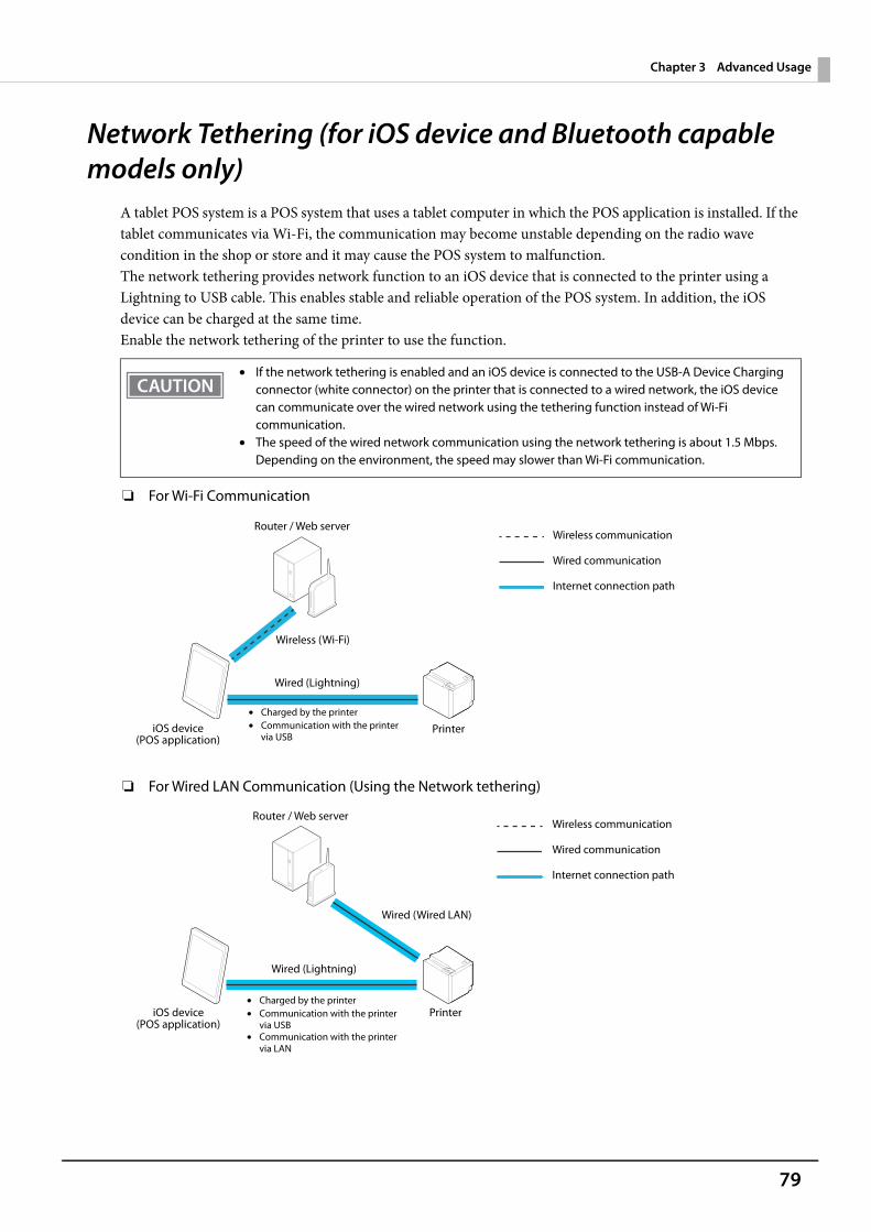
79
Chapter 3 Advanced Usage
Network Tethering (for iOS device and Bluetooth capable models only)
A tablet POS system is a POS system that uses a tablet computer in which the POS application is installed. If the tablet communicates via Wi-Fi, the communication may become unstable depending on the radio wave condition in the shop or store and it may cause the POS system to malfunction.The network tethering provides network function to an iOS device that is connected to the printer using a Lightning to USB cable. This enables stable and reliable operation of the POS system. In addition, the iOS device can be charged at the same time. Enable the network tethering of the printer to use the function.
❏ For Wi-Fi Communication
❏ For Wired LAN Communication (Using the Network tethering)
• If the network tethering is enabled and an iOS device is connected to the USB-A Device Charging connector (white connector) on the printer that is connected to a wired network, the iOS device can communicate over the wired network using the tethering function instead of Wi-Fi communication.
• The speed of the wired network communication using the network tethering is about 1.5 Mbps. Depending on the environment, the speed may slower than Wi-Fi communication.
Wireless communication
Wired communication
Internet connection path
iOS device(POS application)
Wired (Lightning)
Wireless (Wi-Fi)
Router / Web server
Printer• Charged by the printer• Communication with the printer
via USB
Wireless communication
Wired communication
Internet connection path
iOS device(POS application)
Wired (Lightning)
Router / Web server
Printer
Wired (Wired LAN)
• Charged by the printer• Communication with the printer
via USB• Communication with the printer
via LAN
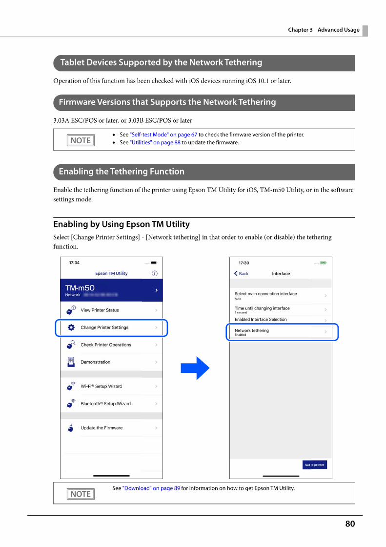
80
Chapter 3 Advanced Usage
Tablet Devices Supported by the Network Tethering
Operation of this function has been checked with iOS devices running iOS 10.1 or later.
Firmware Versions that Supports the Network Tethering
3.03A ESC/POS or later, or 3.03B ESC/POS or later
Enabling the Tethering Function
Enable the tethering function of the printer using Epson TM Utility for iOS, TM-m50 Utility, or in the software settings mode.
Enabling by Using Epson TM UtilitySelect [Change Printer Settings] - [Network tethering] in that order to enable (or disable) the tethering function.
• See "Self-test Mode" on page 67 to check the firmware version of the printer.• See "Utilities" on page 88 to update the firmware.
See "Download" on page 89 for information on how to get Epson TM Utility.
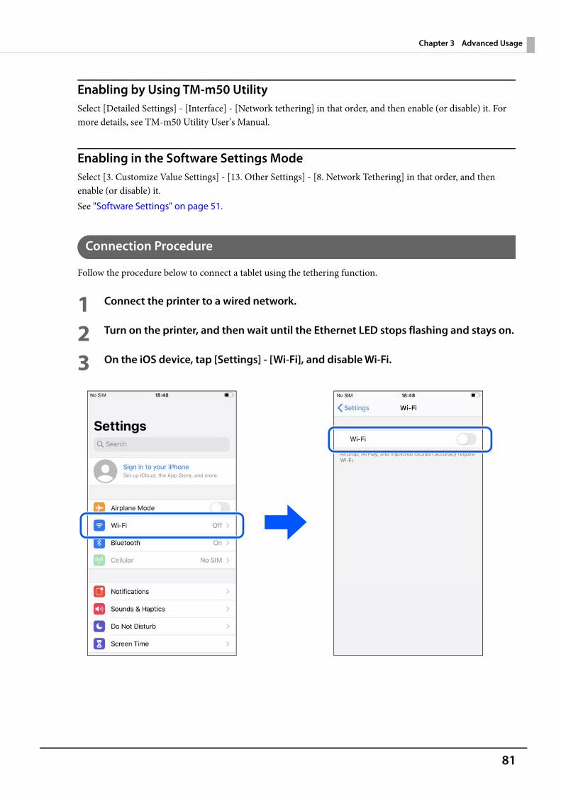
81
Chapter 3 Advanced Usage
Enabling by Using TM-m50 UtilitySelect [Detailed Settings] - [Interface] - [Network tethering] in that order, and then enable (or disable) it. For more details, see TM-m50 Utility User’s Manual.
Enabling in the Software Settings ModeSelect [3. Customize Value Settings] - [13. Other Settings] - [8. Network Tethering] in that order, and then enable (or disable) it. See "Software Settings" on page 51.
Connection Procedure
Follow the procedure below to connect a tablet using the tethering function.
1 Connect the printer to a wired network.
2 Turn on the printer, and then wait until the Ethernet LED stops flashing and stays on.
3 On the iOS device, tap [Settings] - [Wi-Fi], and disable Wi-Fi.
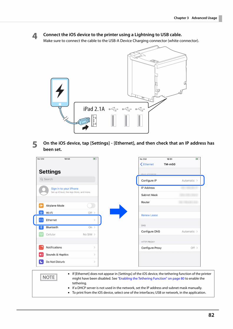
82
Chapter 3 Advanced Usage
4 Connect the iOS device to the printer using a Lightning to USB cable.Make sure to connect the cable to the USB-A Device Charging connector (white connector).
5 On the iOS device, tap [Settings] - [Ethernet], and then check that an IP address hasbeen set.
• If [Ethernet] does not appear in [Settings] of the iOS device, the tethering function of the printer might have been disabled. See "Enabling the Tethering Function" on page 80 to enable the tethering.
• If a DHCP server is not used in the network, set the IP address and subnet mask manually.• To print from the iOS device, select one of the interfaces; USB or network, in the application.
83
Chapter 4 Application Development Information
Application Development InformationThis chapter describes how to control the printer and gives information useful for printer application development.
Controlling the PrinterThe printer supports the following command systems:• ePOS-Print XML• ESC/POS
Users can control the printer by using the aforementioned commands, or the following development kits or drivers.• Epson ePOS SDK• OPOS ADK• OPOS ADK for .NET• JavaPOS ADK• EPSON Advanced Printer Driver (APD)• EPSON TM Virtual Port Driver• Mac Printer Driver• Epson TM/BA Series Thermal Printer Driver
ePOS-Print XML
ePOS-Print XML is the Epson original control command system for POS printers defined in XML. With ePOS-Print XML commands, you can print in environments where http communication is available and from OS applications. For detailed information about ePOS-Print XML, see the ePOS-Print XML User's Manual.
ESC/POS
ESC/POS is the Epson original printer command system for POS printers and customer display. With ESC/POS commands, you can directly control all the printer functions, but detailed knowledge of printer specifications or combination of commands is required, compared to using drivers and applications.For detailed information about ESC/POS commands, see the ESC/POS Command Reference that can be accessed from the following URL.U www.epson-biz.com/pos/reference/

84
Chapter 4 Application Development Information
Controlling the Cash DrawerA pulse output is sent to drawer kick connector pin 2 or pin 5, and you can open the drawer.You can also check the open/close status of the drawer by checking the signal level of the drawer kick connectorpin 3.These controls are executed by a driver or by commands.
ESC/POS CommandsPrepare the output command for the specified pulse and the status transmission command.For details, see the ESC/POS Command Reference.
For Windows Printer Drivers (APD)You can set the drawer to open when printing is started. For details, see the manual for drivers.For details on control, see the manual for Status API of the driver.
OPOS (OCX Driver)Register a cash drawer using the SetupPOS Utility, and control using the OpenDrawer method or the DirectIOfunction.For details, see the "EPSON OPOS ADK MANUAL APPLICATION DEVELOPMENT GUIDE Cash Drawer"and the "UnifiedPOS Specification".
OPOS for .NETRegister a cash drawer using the SetupPOS Utility, and control using the OpenDrawer method or the DirectIOfunction.For details, see the "EPSON OPOS ADK for .NET MANUAL Application Development Guide Cash Drawer(EPSON Standard)" and the "UnifiedPOS Specification".
Epson ePOS SDKThe output command for the drawer kick pulse and the status transmission command are provided in eachSDK library. For details, see the user's manuals provided with each SDK.
• Whether or not pin 2 or pin 5 operates the drawer kick connector depends on the connected cashdrawer.
• You can acquire documents regarding the UnifiedPOS from the following link.https://www.omg.org/retail/unified-pos.htm
85
Chapter 4 Application Development Information
Controlling the Optional External BuzzerYou can set the optional external buzzer to buzz when an error occurs and when an automatic cut off occurs.By using the driver or the command, you can specify when to sound the buzzer.In addition, the beep pattern and how many times to sound the buzzer can be changed.
ESC/POS CommandUse the buzzer control command or the output command for the specified pulse.For details, see the ESC/POS Command Reference.
For Windows Printer Drivers (APD)Use the DirectIO function or the API for opening the drawer. For details, see the manual for Status API of thedrivers.
OPOS (OCX Driver)Register a POS printer using the SetupPOS Utility and control using the DirectIO function.For details, see the "EPSON OPOS ADK MANUAL APPLICATION DEVELOPMENT GUIDE POSPrinter(TM Series)".
OPOS for .NETRegister a POS printer using the SetupPOS Utility and control using the DirectIO function.For details, see the "EPSON OPOS ADK for .NET MANUAL Application Development Guide POSPrinter".
Epson ePOS SDKThe command for the buzzer function is provided in each SDK library. For details, see the user's manuals pro-vided with each SDK.
For details on setting the optional external buzzer, see "Connecting the Optional External Buzzer" onpage 37.
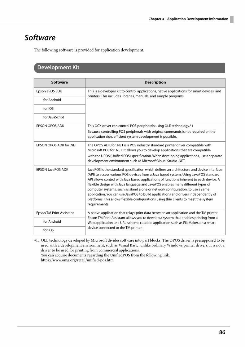
86
Chapter 4 Application Development Information
SoftwareThe following software is provided for application development.
Development Kit
∗1: OLE technology developed by Microsoft divides software into part blocks. The OPOS driver is presupposed to be used with a development environment, such as Visual Basic, unlike ordinary Windows printer drivers. It is not a driver to be used for printing from commercial applications. You can acquire documents regarding the UnifiedPOS from the following link.https://www.omg.org/retail/unified-pos.htm
Software Description
Epson ePOS SDK This is a developer kit to control applications, native applications for smart devices, and printers. This includes libraries, manuals, and sample programs.
for Android
for iOS
for JavaScript
EPSON OPOS ADK This OCX driver can control POS peripherals using OLE technology.*1
Because controlling POS peripherals with original commands is not required on the application side, efficient system development is possible.
EPSON OPOS ADK for .NET The OPOS ADK for .NET is a POS industry standard printer driver compatible with Microsoft POS for .NET. It allows you to develop applications that are compatible
with the UPOS (Unified POS) specification. When developing applications, use a separate development environment such as Microsoft Visual Studio .NET.
EPSON JavaPOS ADK JavaPOS is the standard specification which defines an architecture and device interface (API) to access various POS devices from a Java based system. Using JavaPOS standard API allows control with Java based applications of functions inherent to each device. A flexible design with Java language and JavaPOS enables many different types of computer systems, such as stand alone or network configuration, to use a same application. You can use JavaPOS to build applications and drivers independently of platforms. This allows flexible configurations using thin clients to meet the system requirements.
Epson TM Print Assistant A native application that relays print data between an application and the TM printer.Epson TM Print Assistant allows you to develop a system that enables printing from a Web application or a URL-scheme capable application such as FileMaker, on a smart device connected to the TM printer.
for Android
for iOS
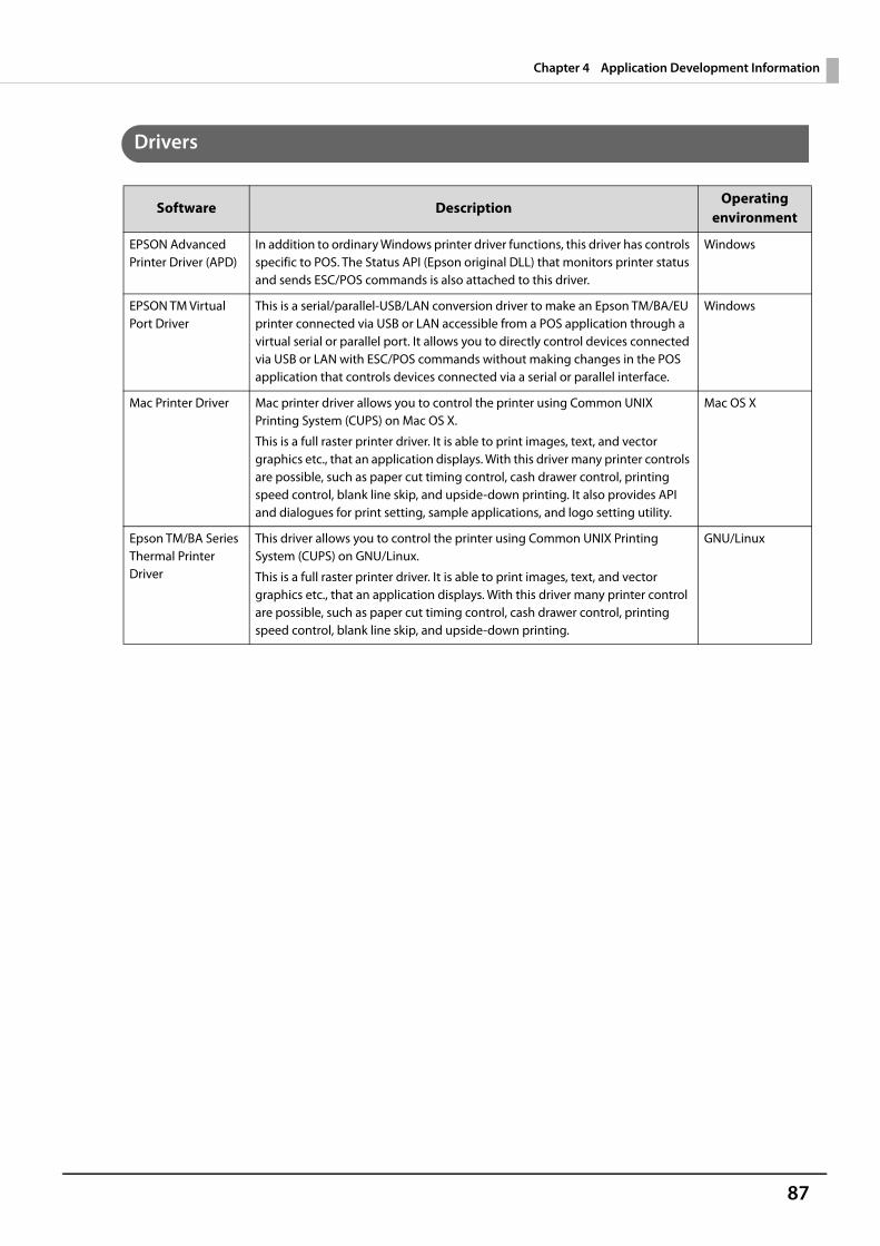
87
Chapter 4 Application Development Information
Drivers
Software DescriptionOperating
environment
EPSON Advanced Printer Driver (APD)
In addition to ordinary Windows printer driver functions, this driver has controls specific to POS. The Status API (Epson original DLL) that monitors printer status and sends ESC/POS commands is also attached to this driver.
Windows
EPSON TM Virtual Port Driver
This is a serial/parallel-USB/LAN conversion driver to make an Epson TM/BA/EU printer connected via USB or LAN accessible from a POS application through a virtual serial or parallel port. It allows you to directly control devices connected via USB or LAN with ESC/POS commands without making changes in the POS application that controls devices connected via a serial or parallel interface.
Windows
Mac Printer Driver Mac printer driver allows you to control the printer using Common UNIX Printing System (CUPS) on Mac OS X.
This is a full raster printer driver. It is able to print images, text, and vector graphics etc., that an application displays. With this driver many printer controls are possible, such as paper cut timing control, cash drawer control, printing speed control, blank line skip, and upside-down printing. It also provides API and dialogues for print setting, sample applications, and logo setting utility.
Mac OS X
Epson TM/BA Series Thermal Printer Driver
This driver allows you to control the printer using Common UNIX Printing System (CUPS) on GNU/Linux.
This is a full raster printer driver. It is able to print images, text, and vector graphics etc., that an application displays. With this driver many printer control are possible, such as paper cut timing control, cash drawer control, printing speed control, blank line skip, and upside-down printing.
GNU/Linux
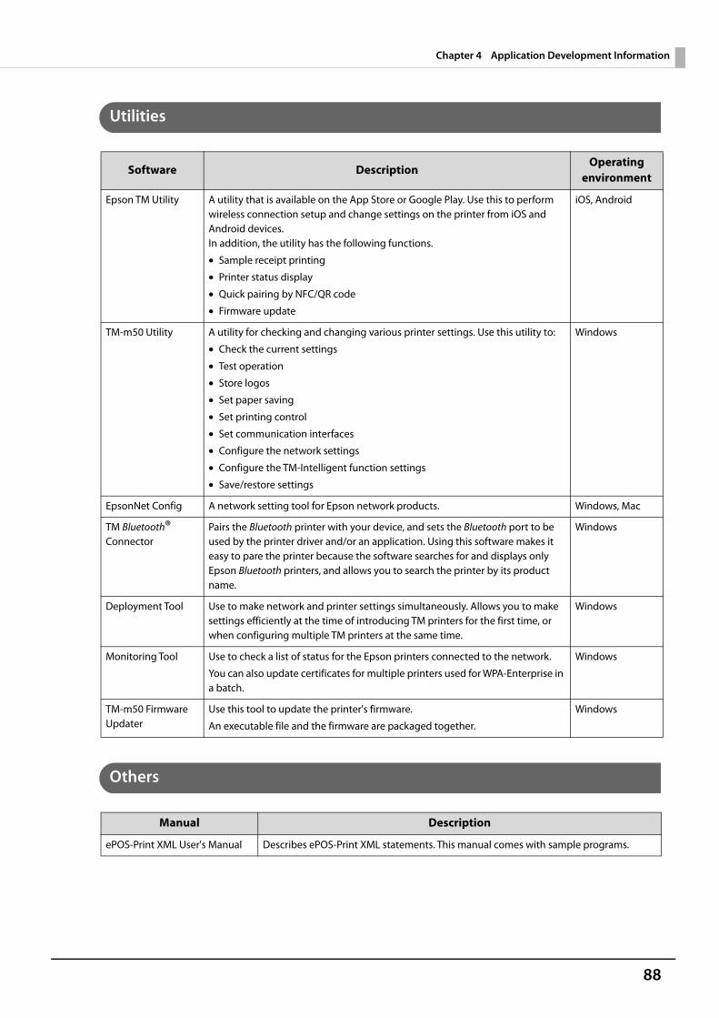
88
Chapter 4 Application Development Information
Utilities
Others
Software DescriptionOperating
environment
Epson TM Utility A utility that is available on the App Store or Google Play. Use this to perform wireless connection setup and change settings on the printer from iOS and Android devices. In addition, the utility has the following functions.
• Sample receipt printing
• Printer status display
• Quick pairing by NFC/QR code
• Firmware update
iOS, Android
TM-m50 Utility A utility for checking and changing various printer settings. Use this utility to:
• Check the current settings
• Test operation
• Store logos
• Set paper saving
• Set printing control
• Set communication interfaces
• Configure the network settings
• Configure the TM-Intelligent function settings
• Save/restore settings
Windows
EpsonNet Config A network setting tool for Epson network products. Windows, Mac
TM Bluetooth® Connector
Pairs the Bluetooth printer with your device, and sets the Bluetooth port to be used by the printer driver and/or an application. Using this software makes it easy to pare the printer because the software searches for and displays only Epson Bluetooth printers, and allows you to search the printer by its product name.
Windows
Deployment Tool Use to make network and printer settings simultaneously. Allows you to make settings efficiently at the time of introducing TM printers for the first time, or when configuring multiple TM printers at the same time.
Windows
Monitoring Tool Use to check a list of status for the Epson printers connected to the network.
You can also update certificates for multiple printers used for WPA-Enterprise in a batch.
Windows
TM-m50 Firmware Updater
Use this tool to update the printer's firmware.
An executable file and the firmware are packaged together.
Windows
Manual Description
ePOS-Print XML User's Manual Describes ePOS-Print XML statements. This manual comes with sample programs.

89
Chapter 4 Application Development Information
Download
You can obtain software and manuals from one of the following URLs.For customers in North America, go to the following web site:U www.epson.com/support/For customers in other countries, go to the following web site:U www.epson-biz.com/
90
Chapter 4 Application Development Information
Application Development and Distribution for iOSIf your application enables communication with the printer using Bluetooth or a Lightning-USB cable, Epson must submit the application to Apple before you submit it to the App Store. Please apply for each application you want to submit to the App Store from the URL below.U www.epson-biz.com/ais/E/
Notes on Printing Barcodes and Two-Dimensional Symbols• Ensure adequate space around the code; “quiet zone” that is required for the code.• To print PDF417 (two-dimensional symbol), the following settings are recommended.
Module height: 3 to 5 times the module widthVertical size of the symbol: approximately 5 mm {0.20"} or more
• The recognition rate of ladder bar codes and two-dimensional symbols may vary depending on widths of themodules, print density, environmental temperature, type of paper, and characteristics of the reader. Makesure to check the recognition rate beforehand to determine the settings and use conditions so that the restric-tions of the reader are satisfied.
• Reading quality of multi-gradation bar codes and two-dimensional symbols is not guaranteed.• When printing a ladder barcode or two-dimensional symbol that is created as a graphics data, set the print
speed to level 5.
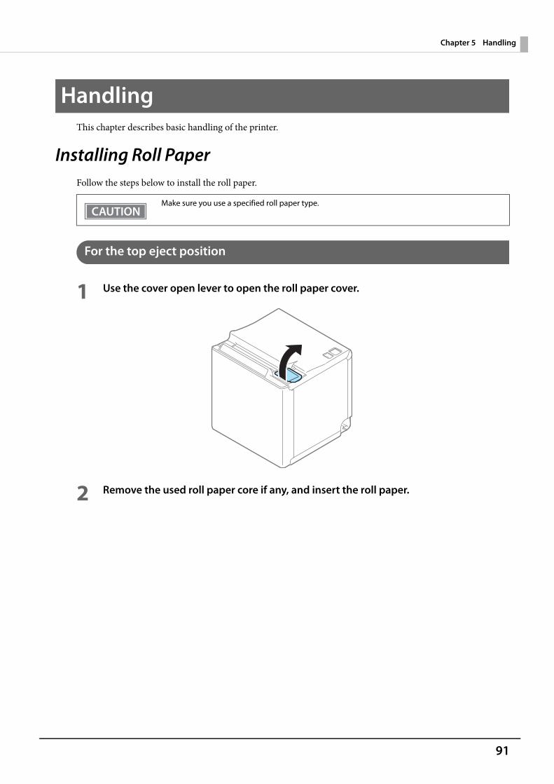
91
Chapter 5 Handling
HandlingThis chapter describes basic handling of the printer.
Installing Roll PaperFollow the steps below to install the roll paper.
For the top eject position
1 Use the cover open lever to open the roll paper cover.
2 Remove the used roll paper core if any, and insert the roll paper.
Make sure you use a specified roll paper type.
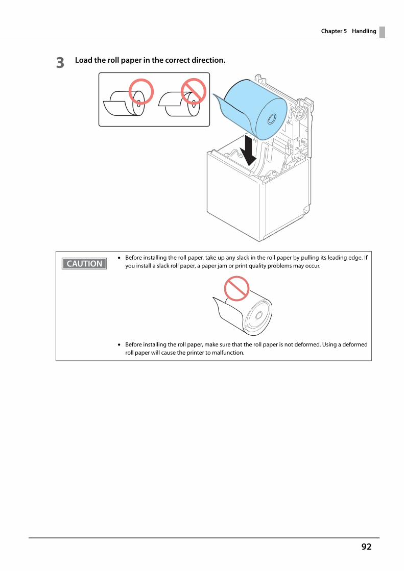
92
Chapter 5 Handling
3 Load the roll paper in the correct direction.
• Before installing the roll paper, take up any slack in the roll paper by pulling its leading edge. Ifyou install a slack roll paper, a paper jam or print quality problems may occur.
• Before installing the roll paper, make sure that the roll paper is not deformed. Using a deformedroll paper will cause the printer to malfunction.
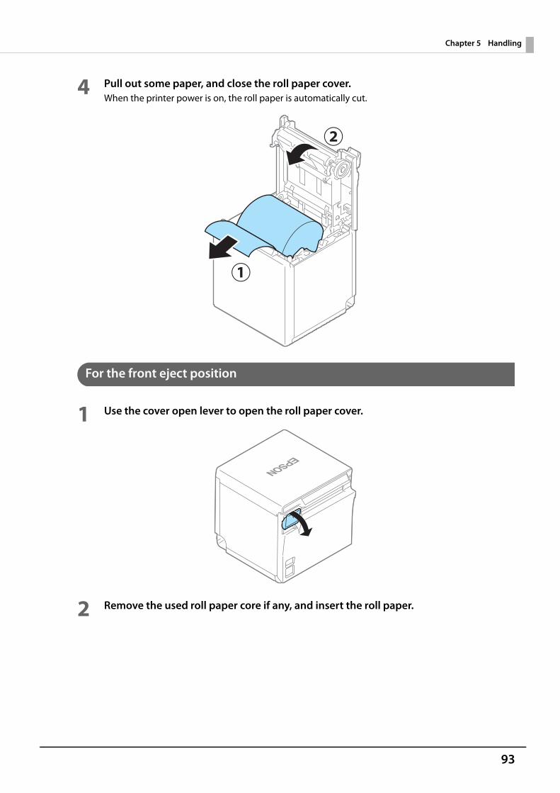
93
Chapter 5 Handling
4 Pull out some paper, and close the roll paper cover.When the printer power is on, the roll paper is automatically cut.
For the front eject position
1 Use the cover open lever to open the roll paper cover.
2 Remove the used roll paper core if any, and insert the roll paper.
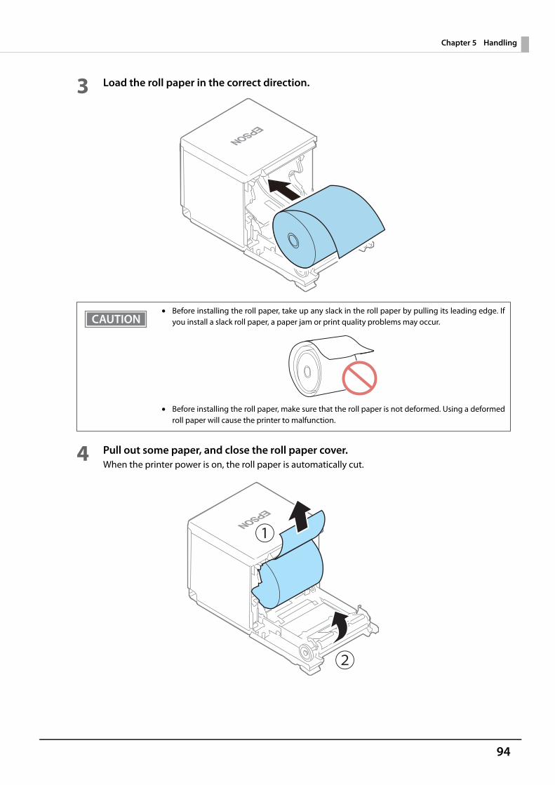
94
Chapter 5 Handling
3 Load the roll paper in the correct direction.
4 Pull out some paper, and close the roll paper cover.When the printer power is on, the roll paper is automatically cut.
• Before installing the roll paper, take up any slack in the roll paper by pulling its leading edge. Ifyou install a slack roll paper, a paper jam or print quality problems may occur.
• Before installing the roll paper, make sure that the roll paper is not deformed. Using a deformedroll paper will cause the printer to malfunction.
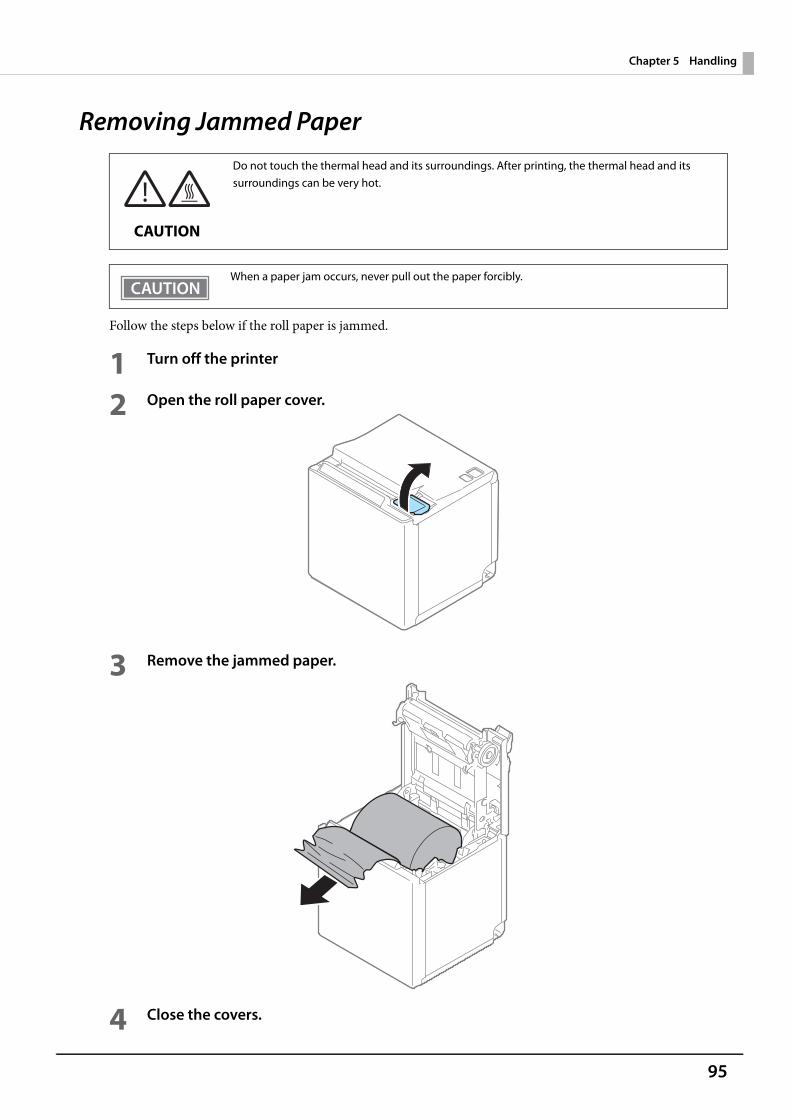
95
Chapter 5 Handling
Removing Jammed Paper
Follow the steps below if the roll paper is jammed.
1 Turn off the printer
2 Open the roll paper cover.
3 Remove the jammed paper.
4 Close the covers.
Do not touch the thermal head and its surroundings. After printing, the thermal head and its surroundings can be very hot.
CAUTION
When a paper jam occurs, never pull out the paper forcibly.
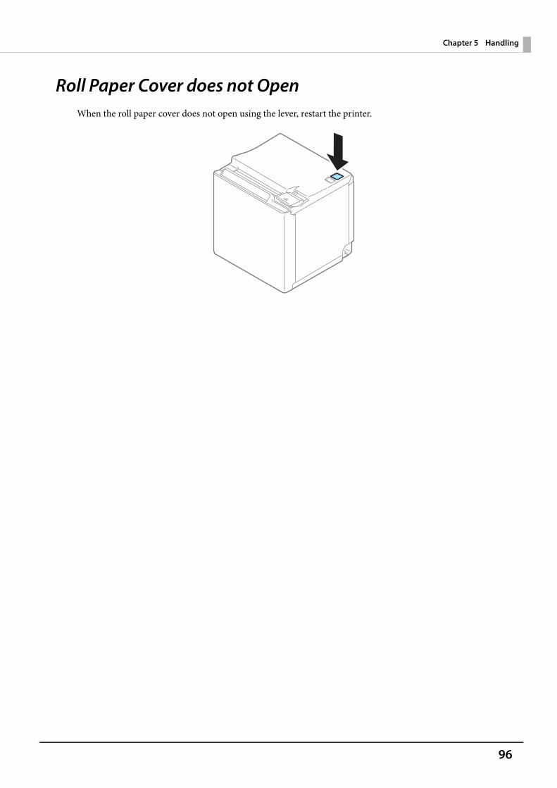
96
Chapter 5 Handling
Roll Paper Cover does not OpenWhen the roll paper cover does not open using the lever, restart the printer.
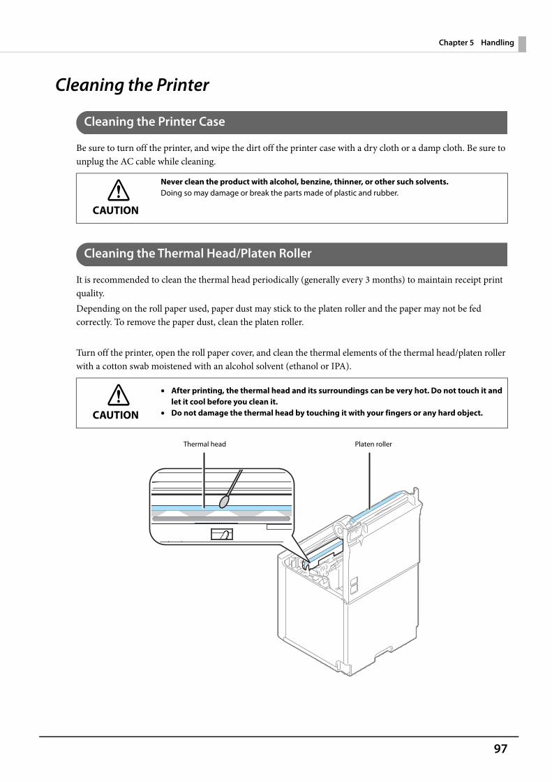
97
Chapter 5 Handling
Cleaning the Printer
Cleaning the Printer Case
Be sure to turn off the printer, and wipe the dirt off the printer case with a dry cloth or a damp cloth. Be sure to unplug the AC cable while cleaning.
Cleaning the Thermal Head/Platen Roller
It is recommended to clean the thermal head periodically (generally every 3 months) to maintain receipt print quality.Depending on the roll paper used, paper dust may stick to the platen roller and the paper may not be fed correctly. To remove the paper dust, clean the platen roller.
Turn off the printer, open the roll paper cover, and clean the thermal elements of the thermal head/platen roller with a cotton swab moistened with an alcohol solvent (ethanol or IPA).
CAUTION
Never clean the product with alcohol, benzine, thinner, or other such solvents.Doing so may damage or break the parts made of plastic and rubber.
CAUTION
• After printing, the thermal head and its surroundings can be very hot. Do not touch it andlet it cool before you clean it.
• Do not damage the thermal head by touching it with your fingers or any hard object.
Platen rollerThermal head
98
Chapter 5 Handling
Preparing for TransportFollow the steps below to transport the printer.
1 Turn off the printer.
2 Confirm that the Power LED is off.
3 Disconnect the AC cable from the socket.
4 Remove the roll paper.
5 Pack the printer upright.
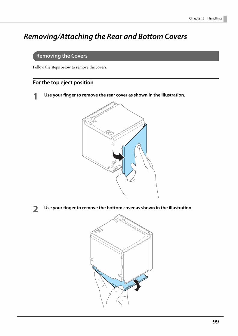
99
Chapter 5 Handling
Removing/Attaching the Rear and Bottom Covers
Removing the Covers
Follow the steps below to remove the covers.
For the top eject position
1 Use your finger to remove the rear cover as shown in the illustration.
2 Use your finger to remove the bottom cover as shown in the illustration.
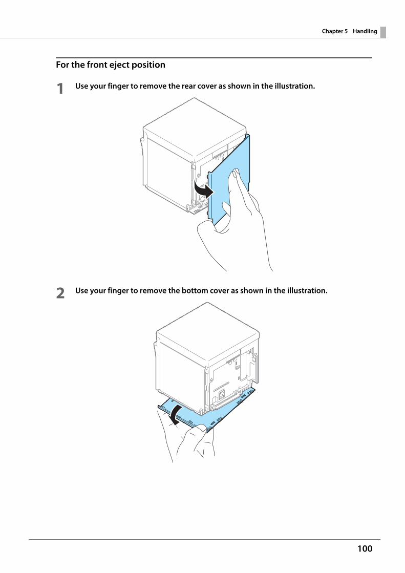
100
Chapter 5 Handling
For the front eject position
1 Use your finger to remove the rear cover as shown in the illustration.
2 Use your finger to remove the bottom cover as shown in the illustration.
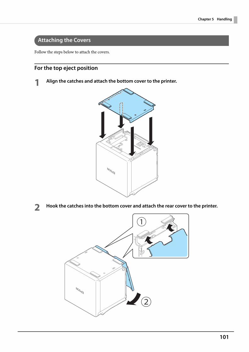
101
Chapter 5 Handling
Attaching the Covers
Follow the steps below to attach the covers.
For the top eject position
1 Align the catches and attach the bottom cover to the printer.
2 Hook the catches into the bottom cover and attach the rear cover to the printer.
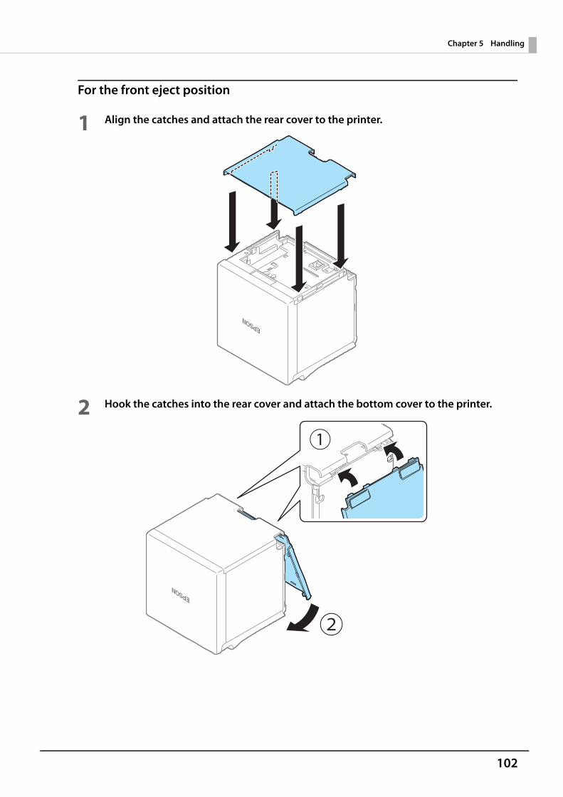
102
Chapter 5 Handling
For the front eject position
1 Align the catches and attach the rear cover to the printer.
2 Hook the catches into the rear cover and attach the bottom cover to the printer.
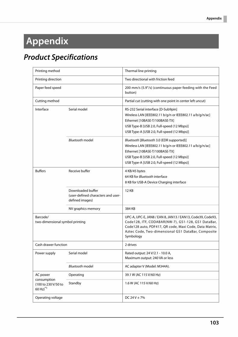
103
Appendix
Appendix
Product Specifications
Printing method Thermal line printing
Printing direction Two directional with friction feed
Paper feed speed 200 mm/s {5.9"/s} (continuous paper feeding with the Feedbutton)
Cutting method Partial cut (cutting with one point in center left uncut)
Interface Serial model RS-232 Serial interface [D-Sub9pin]
Wireless LAN [IEEE802.11 b/g/n or IEEE802.11 a/b/g/n/ac]
Ethernet [10BASE-T/100BASE-TX]
USB Type-B [USB 2.0, Full-speed (12 Mbps)]
USB Type-A [USB 2.0, Full-speed (12 Mbps)]
Bluetooth model Bluetooth [Bluetooth 3.0 (EDR supported)]
Wireless LAN [IEEE802.11 b/g/n or IEEE802.11 a/b/g/n/ac]
Ethernet [10BASE-T/100BASE-TX]
USB Type-B [USB 2.0, Full-speed (12 Mbps)]
USB Type-A [USB 2.0, Full-speed (12 Mbps)]
Buffers Receive buffer 4 KB/45 bytes
64 KB for Bluetooth interface
8 KB for USB-A Device Charging interface
Downloaded buffer(user-defined characters and user-defined images)
12 KB
NV graphics memory 384 KB
Barcode/two-dimensional symbol printing
UPC-A, UPC-E, JAN8 / EAN 8, JAN13 / EAN13, Code39, Code93,Code128, ITF, CODABAR(NW-7), GS1-128, GS1 DataBar,Code128 auto, PDF417, QR code, Maxi Code, Data Matrix,Aztec Code, Two-dimensional GS1 DataBar, CompositeSymbology
Cash drawer function 2 drives
Power supply Serial model Rated output: 24 V/2.1 - 10.0 A, Maximum output: 240 VA or less
Bluetooth model AC adapter V (Model: M344A).
AC power consumption(100 to 230 V/50 to 60 Hz)*1
Operating 39.1 W (AC 115 V/60 Hz)
Standby 1.6 W (AC 115 V/60 Hz)
Operating voltage DC 24 V ± 7%
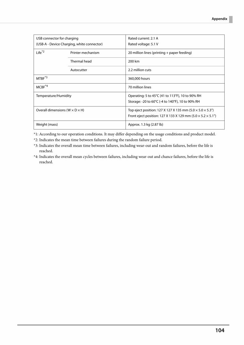
104
Appendix
*1: According to our operation conditions. It may differ depending on the usage conditions and product model.*2: Indicates the mean time between failures during the random failure period.*3: Indicates the overall mean time between failures, including wear-out and random failures, before the life is
reached.*4: Indicates the overall mean cycles between failures, including wear-out and chance failures, before the life is
reached.
USB connector for charging
(USB-A - Device Charging, white connector)
Rated current: 2.1 A
Rated voltage: 5.1 V
Life*2 Printer mechanism 20 million lines (printing + paper feeding)
Thermal head 200 km
Autocutter 2.2 million cuts
MTBF*3 360,000 hours
MCBF*4 70 million lines
Temperature/Humidity Operating: 5 to 45°C {41 to 113°F}, 10 to 90% RH
Storage: -20 to 60°C {-4 to 140°F}, 10 to 90% RH
Overall dimensions (W × D × H) Top eject position: 127 X 127 X 135 mm (5.0 × 5.0 × 5.3")
Front eject position: 127 X 133 X 129 mm (5.0 × 5.2 × 5.1")
Weight (mass) Approx. 1.3 kg {2.87 lb}
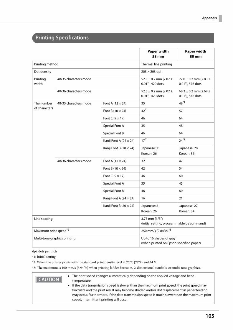
105
Appendix
Printing Specifications
dpi: dots per inch*1: Initial setting*2: When the printer prints with the standard print density level at 25°C {77°F} and 24 V.*3: The maximum is 100 mm/s {3.94"/s} when printing ladder barcodes, 2-dimensional symbols, or multi-tone graphics.
Paper width 58 mm
Paper width 80 mm
Printing method Thermal line printing
Dot density 203 × 203 dpi
Printing width
48/35 characters mode 52.5 ± 0.2 mm {2.07 ± 0.01"}, 420 dots
72.0 ± 0.2 mm {2.83 ± 0.01"}, 576 dots
48/36 characters mode 52.5 ± 0.2 mm {2.07 ± 0.01"}, 420 dots
68.3 ± 0.2 mm {2.69 ± 0.01"}, 546 dots
The number of characters
48/35 characters mode Font A (12 × 24) 35 48*1
Font B (10 × 24) 42*1 57
Font C (9 × 17) 46 64
Special Font A 35 48
Special Font B 46 64
Kanji Font A (24 × 24) 17*1 24*1
Kanji Font B (20 × 24) Japanese: 21
Korean: 26
Japanese: 28
Korean: 36
48/36 characters mode Font A (12 × 24) 32 42
Font B (10 × 24) 42 54
Font C (9 × 17) 46 60
Special Font A 35 45
Special Font B 46 60
Kanji Font A (24 × 24) 16 21
Kanji Font B (20 × 24) Japanese: 21
Korean: 26
Japanese: 27
Korean: 34
Line spacing 3.75 mm {1/5"} (initial setting, programmable by command)
Maximum print speed*2 250 mm/s {9.84"/s}*3
Multi-tone graphics printing Up to 16 shades of gray(when printed on Epson specified paper)
• The print speed changes automatically depending on the applied voltage and head temperature.
• If the data transmission speed is slower than the maximum print speed, the print speed may fluctuate and the print result may become shaded and/or dot displacement in paper feeding may occur. Furthermore, if the data transmission speed is much slower than the maximum print speed, intermittent printing will occur.
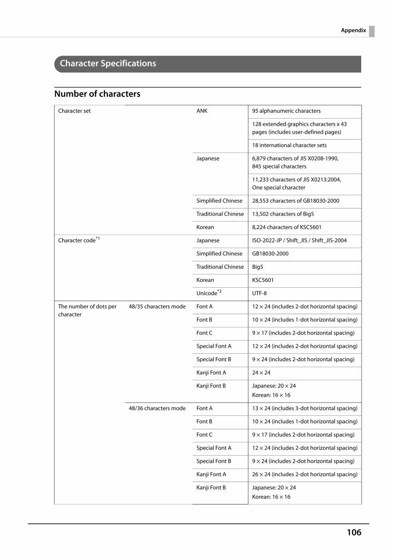
106
Appendix
Character Specifications
Number of characters
Character set ANK 95 alphanumeric characters
128 extended graphics characters x 43 pages (includes user-defined pages)
18 international character sets
Japanese 6,879 characters of JIS X0208-1990, 845 special characters
11,233 characters of JIS X0213:2004, One special character
Simplified Chinese 28,553 characters of GB18030-2000
Traditional Chinese 13,502 characters of Big5
Korean 8,224 characters of KSC5601
Character code*1 Japanese ISO-2022-JP / Shift_JIS / Shift_JIS-2004
Simplified Chinese GB18030-2000
Traditional Chinese Big5
Korean KSC5601
Unicode*2 UTF-8
The number of dots per character
48/35 characters mode Font A 12 × 24 (includes 2-dot horizontal spacing)
Font B 10 × 24 (includes 1-dot horizontal spacing)
Font C 9 × 17 (includes 2-dot horizontal spacing)
Special Font A 12 × 24 (includes 2-dot horizontal spacing)
Special Font B 9 × 24 (includes 2-dot horizontal spacing)
Kanji Font A 24 × 24
Kanji Font B Japanese: 20 × 24
Korean: 16 × 16
48/36 characters mode Font A 13 × 24 (includes 3-dot horizontal spacing)
Font B 10 × 24 (includes 1-dot horizontal spacing)
Font C 9 × 17 (includes 2-dot horizontal spacing)
Special Font A 12 × 24 (includes 2-dot horizontal spacing)
Special Font B 9 × 24 (includes 2-dot horizontal spacing)
Kanji Font A 26 × 24 (includes 2-dot horizontal spacing)
Kanji Font B Japanese: 20 × 24
Korean: 16 × 16
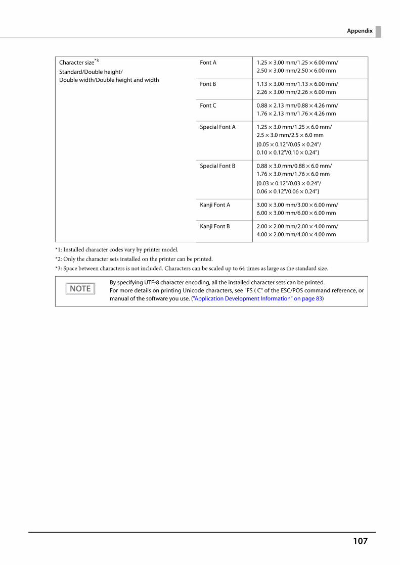
107
Appendix
*1: Installed character codes vary by printer model.*2: Only the character sets installed on the printer can be printed.*3: Space between characters is not included. Characters can be scaled up to 64 times as large as the standard size.
Character size*3
Standard/Double height/Double width/Double height and width
Font A 1.25 × 3.00 mm/1.25 × 6.00 mm/2.50 × 3.00 mm/2.50 × 6.00 mm
Font B 1.13 × 3.00 mm/1.13 × 6.00 mm/2.26 × 3.00 mm/2.26 × 6.00 mm
Font C 0.88 × 2.13 mm/0.88 × 4.26 mm/1.76 × 2.13 mm/1.76 × 4.26 mm
Special Font A 1.25 × 3.0 mm/1.25 × 6.0 mm/2.5 × 3.0 mm/2.5 × 6.0 mm
{0.05 × 0.12"/0.05 × 0.24"/0.10 × 0.12"/0.10 × 0.24"}
Special Font B 0.88 × 3.0 mm/0.88 × 6.0 mm/1.76 × 3.0 mm/1.76 × 6.0 mm
{0.03 × 0.12"/0.03 × 0.24"/0.06 × 0.12"/0.06 × 0.24"}
Kanji Font A 3.00 × 3.00 mm/3.00 × 6.00 mm/6.00 × 3.00 mm/6.00 × 6.00 mm
Kanji Font B 2.00 × 2.00 mm/2.00 × 4.00 mm/4.00 × 2.00 mm/4.00 × 4.00 mm
By specifying UTF-8 character encoding, all the installed character sets can be printed.For more details on printing Unicode characters, see "FS ( C" of the ESC/POS command reference, ormanual of the software you use. ("Application Development Information" on page 83)
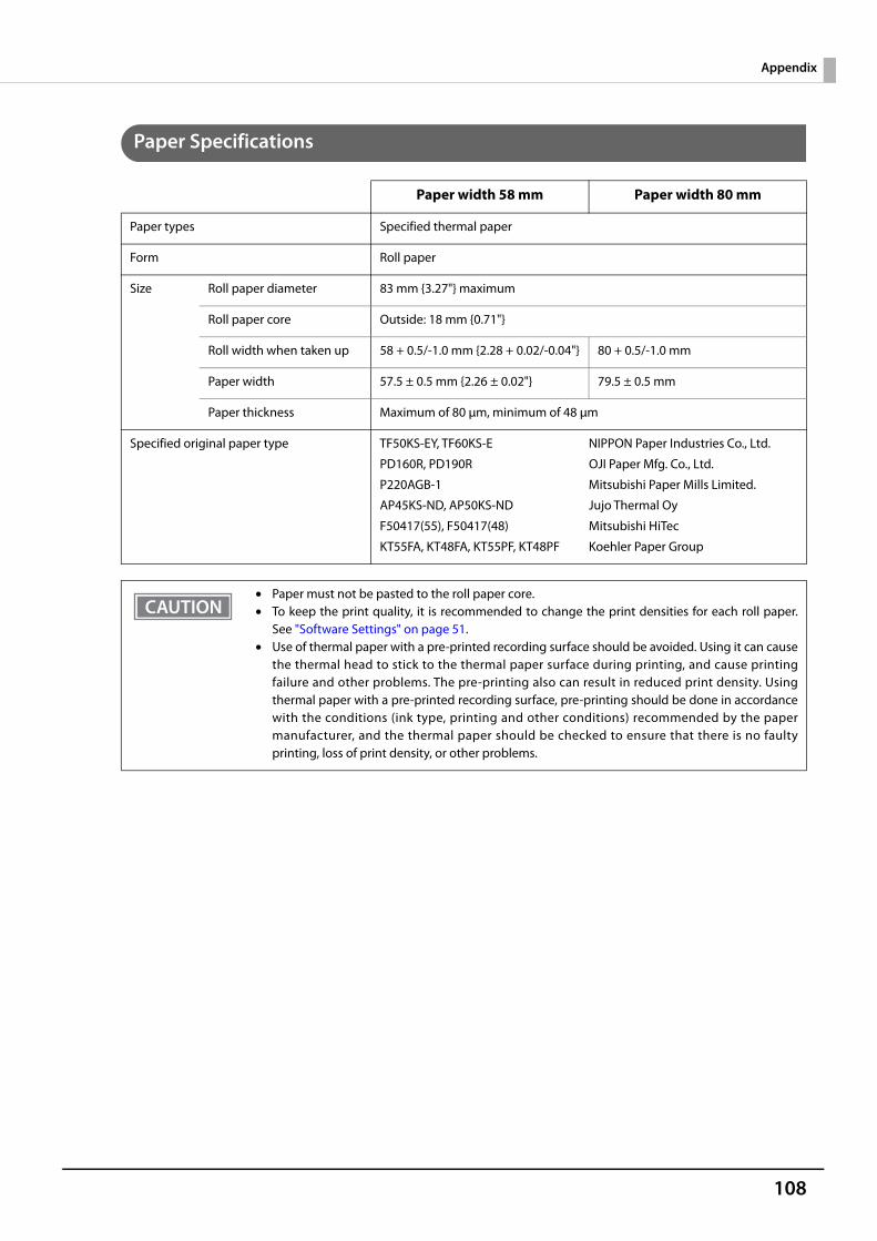
108
Appendix
Paper Specifications
Paper width 58 mm Paper width 80 mm
Paper types Specified thermal paper
Form Roll paper
Size Roll paper diameter 83 mm {3.27"} maximum
Roll paper core Outside: 18 mm {0.71"}
Roll width when taken up 58 + 0.5/-1.0 mm {2.28 + 0.02/-0.04"} 80 + 0.5/-1.0 mm
Paper width 57.5 ± 0.5 mm {2.26 ± 0.02"} 79.5 ± 0.5 mm
Paper thickness Maximum of 80 μm, minimum of 48 μm
Specified original paper type TF50KS-EY, TF60KS-E NIPPON Paper Industries Co., Ltd.
PD160R, PD190R OJI Paper Mfg. Co., Ltd.
P220AGB-1 Mitsubishi Paper Mills Limited.
AP45KS-ND, AP50KS-ND Jujo Thermal Oy
F50417(55), F50417(48) Mitsubishi HiTec
KT55FA, KT48FA, KT55PF, KT48PF Koehler Paper Group
• Paper must not be pasted to the roll paper core.• To keep the print quality, it is recommended to change the print densities for each roll paper.
See "Software Settings" on page 51.• Use of thermal paper with a pre-printed recording surface should be avoided. Using it can cause
the thermal head to stick to the thermal paper surface during printing, and cause printingfailure and other problems. The pre-printing also can result in reduced print density. Usingthermal paper with a pre-printed recording surface, pre-printing should be done in accordancewith the conditions (ink type, printing and other conditions) recommended by the papermanufacturer, and the thermal paper should be checked to ensure that there is no faultyprinting, loss of print density, or other problems.
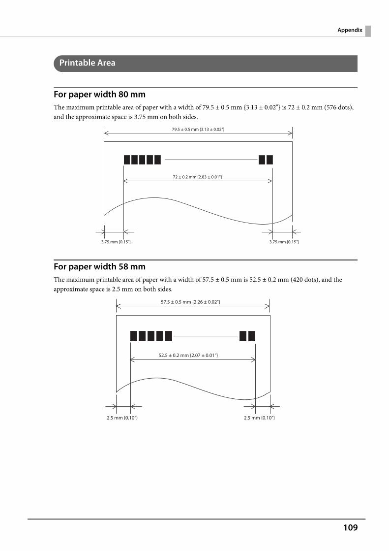
109
Appendix
Printable Area
For paper width 80 mmThe maximum printable area of paper with a width of 79.5 ± 0.5 mm {3.13 ± 0.02"} is 72 ± 0.2 mm (576 dots), and the approximate space is 3.75 mm on both sides.
For paper width 58 mmThe maximum printable area of paper with a width of 57.5 ± 0.5 mm is 52.5 ± 0.2 mm (420 dots), and the approximate space is 2.5 mm on both sides.
79.5 ± 0.5 mm {3.13 ± 0.02"}
72 ± 0.2 mm {2.83 ± 0.01"}
3.75 mm {0.15"} 3.75 mm {0.15"}
57.5 ± 0.5 mm {2.26 ± 0.02”}
52.5 ± 0.2 mm {2.07 ± 0.01”}
2.5 mm {0.10”} 2.5 mm {0.10”}
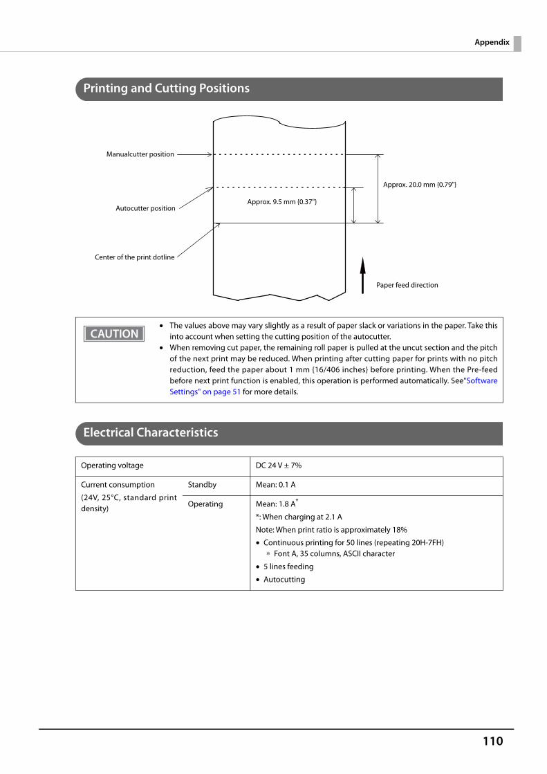
110
Appendix
Printing and Cutting Positions
Electrical Characteristics
• The values above may vary slightly as a result of paper slack or variations in the paper. Take thisinto account when setting the cutting position of the autocutter.
• When removing cut paper, the remaining roll paper is pulled at the uncut section and the pitchof the next print may be reduced. When printing after cutting paper for prints with no pitchreduction, feed the paper about 1 mm {16/406 inches} before printing. When the Pre-feedbefore next print function is enabled, this operation is performed automatically. See"SoftwareSettings" on page 51 for more details.
Operating voltage DC 24 V ± 7%
Current consumption
(24V, 25°C, standard printdensity)
Standby Mean: 0.1 A
Operating Mean: 1.8 A*
*: When charging at 2.1 A
Note: When print ratio is approximately 18%
• Continuous printing for 50 lines (repeating 20H-7FH)∗ Font A, 35 columns, ASCII character
• 5 lines feeding
• Autocutting
Autocutter position
Approx. 20.0 mm {0.79"}
Approx. 9.5 mm {0.37"}
Manualcutter position
Center of the print dotline
Paper feed direction
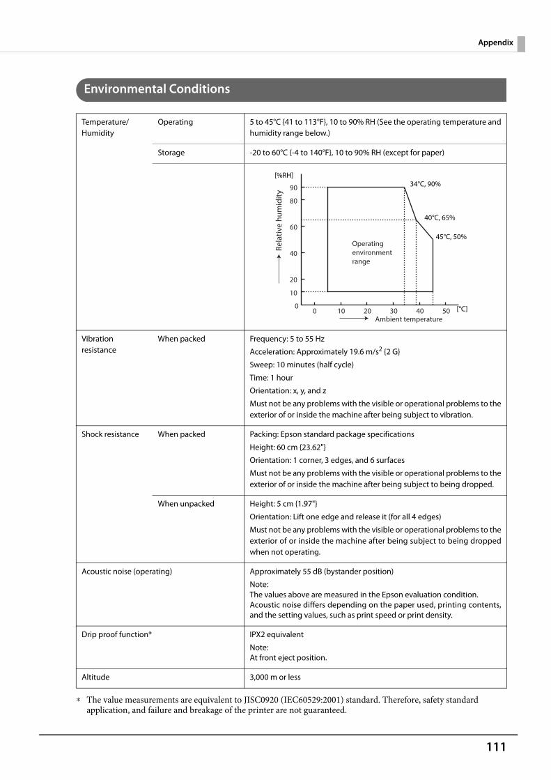
111
Appendix
Environmental Conditions
∗ The value measurements are equivalent to JISC0920 (IEC60529:2001) standard. Therefore, safety standard application, and failure and breakage of the printer are not guaranteed.
Temperature/Humidity
Operating 5 to 45°C {41 to 113°F}, 10 to 90% RH (See the operating temperature andhumidity range below.)
Storage -20 to 60°C {-4 to 140°F}, 10 to 90% RH (except for paper)
Vibration resistance
When packed Frequency: 5 to 55 Hz
Acceleration: Approximately 19.6 m/s2 {2 G}
Sweep: 10 minutes (half cycle)
Time: 1 hour
Orientation: x, y, and z
Must not be any problems with the visible or operational problems to theexterior of or inside the machine after being subject to vibration.
Shock resistance When packed Packing: Epson standard package specifications
Height: 60 cm {23.62"}
Orientation: 1 corner, 3 edges, and 6 surfaces
Must not be any problems with the visible or operational problems to theexterior of or inside the machine after being subject to being dropped.
When unpacked Height: 5 cm {1.97"}
Orientation: Lift one edge and release it (for all 4 edges)
Must not be any problems with the visible or operational problems to theexterior of or inside the machine after being subject to being droppedwhen not operating.
Acoustic noise (operating) Approximately 55 dB (bystander position)
Note:The values above are measured in the Epson evaluation condition.Acoustic noise differs depending on the paper used, printing contents,and the setting values, such as print speed or print density.
Drip proof function* IPX2 equivalent
Note:At front eject position.
Altitude 3,000 m or less
Rela
tive
hum
idity
Operating environmentrange
90
60
80
10
20
40
00
10 20 30 40 50Ambient temperature
[%RH]34°C, 90%
40°C, 65%
45°C, 50%
[°C]
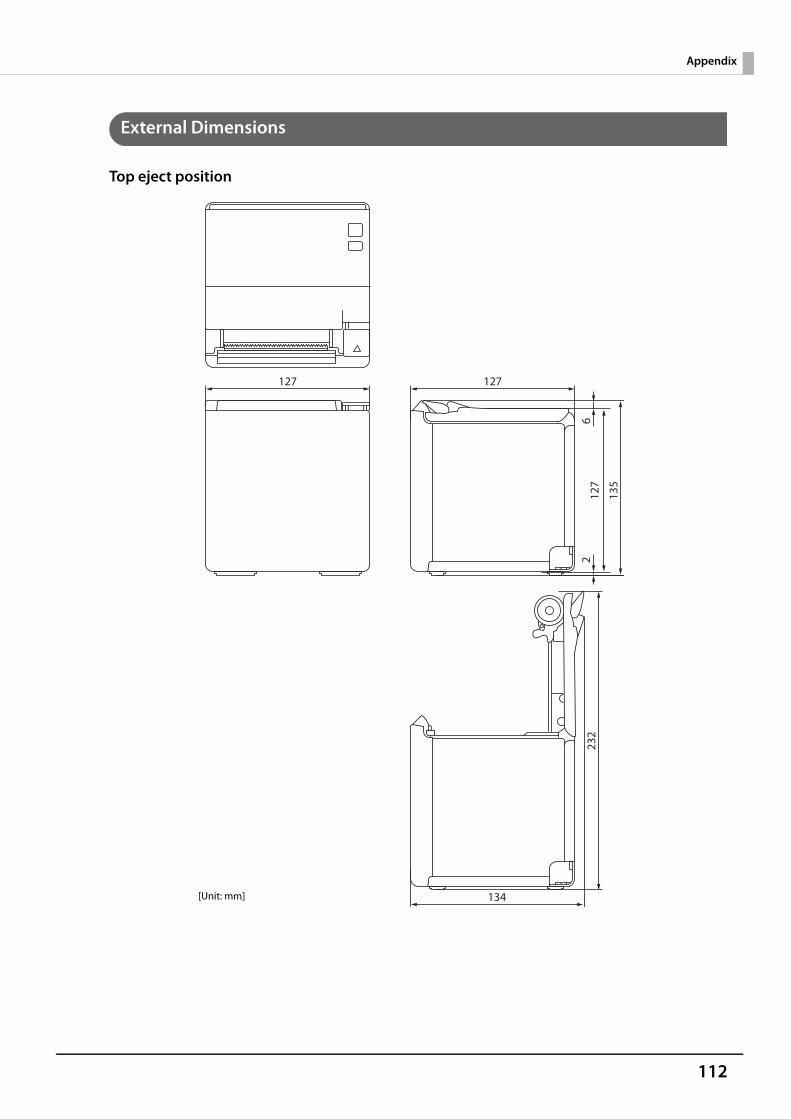
112
Appendix
External Dimensions
Top eject position
127 127
134
232
135
127
26
[Unit: mm]
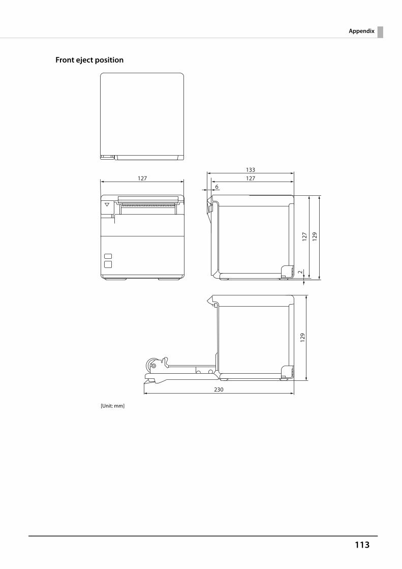
113
Appendix
Front eject position
[Unit: mm]
127
230
129
133127
6
127
2
129
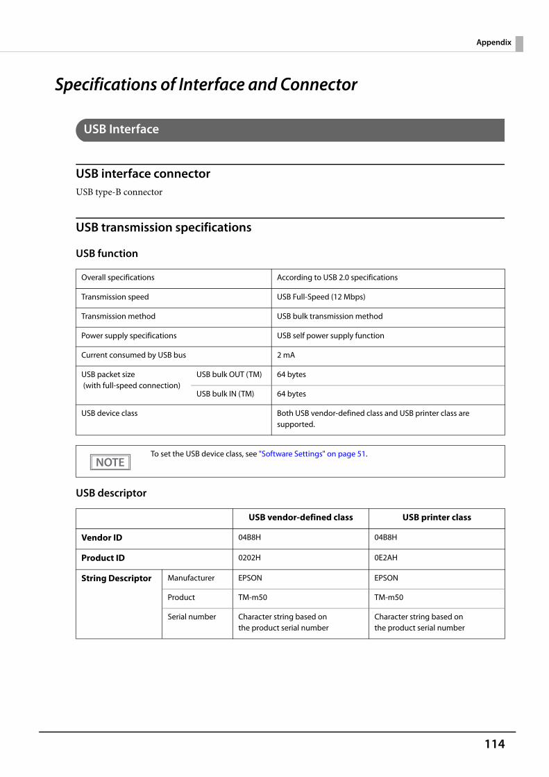
114
Appendix
Specifications of Interface and Connector
USB Interface
USB interface connectorUSB type-B connector
USB transmission specifications
USB function
USB descriptor
Overall specifications According to USB 2.0 specifications
Transmission speed USB Full-Speed (12 Mbps)
Transmission method USB bulk transmission method
Power supply specifications USB self power supply function
Current consumed by USB bus 2 mA
USB packet size (with full-speed connection)
USB bulk OUT (TM) 64 bytes
USB bulk IN (TM) 64 bytes
USB device class Both USB vendor-defined class and USB printer class are supported.
To set the USB device class, see "Software Settings" on page 51.
USB vendor-defined class USB printer class
Vendor ID 04B8H 04B8H
Product ID 0202H 0E2AH
String Descriptor Manufacturer EPSON EPSON
Product TM-m50 TM-m50
Serial number Character string based onthe product serial number
Character string based onthe product serial number
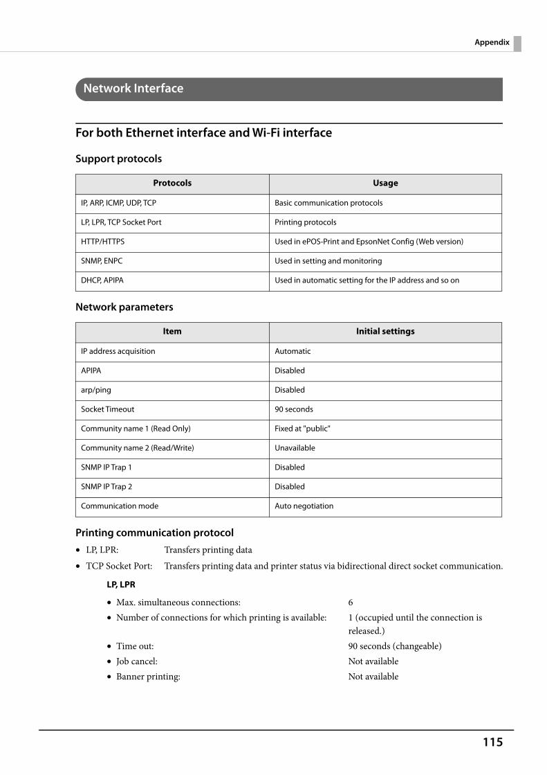
115
Appendix
Network Interface
For both Ethernet interface and Wi-Fi interface
Support protocols
Network parameters
Printing communication protocol• LP, LPR: Transfers printing data• TCP Socket Port: Transfers printing data and printer status via bidirectional direct socket communication.
LP, LPR
Protocols Usage
IP, ARP, ICMP, UDP, TCP Basic communication protocols
LP, LPR, TCP Socket Port Printing protocols
HTTP/HTTPS Used in ePOS-Print and EpsonNet Config (Web version)
SNMP, ENPC Used in setting and monitoring
DHCP, APIPA Used in automatic setting for the IP address and so on
Item Initial settings
IP address acquisition Automatic
APIPA Disabled
arp/ping Disabled
Socket Timeout 90 seconds
Community name 1 (Read Only) Fixed at "public"
Community name 2 (Read/Write) Unavailable
SNMP IP Trap 1 Disabled
SNMP IP Trap 2 Disabled
Communication mode Auto negotiation
• Max. simultaneous connections: 6• Number of connections for which printing is available: 1 (occupied until the connection is
released.)• Time out: 90 seconds (changeable)• Job cancel: Not available• Banner printing: Not available
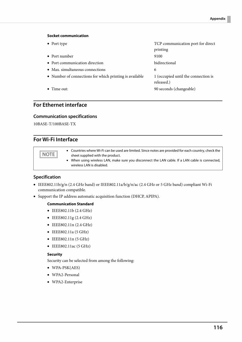
116
Appendix
Socket communication
For Ethernet interface
Communication specifications10BASE-T/100BASE-TX
For Wi-Fi Interface
Specification• IEEE802.11b/g/n (2.4 GHz band) or IEEE802.11a/b/g/n/ac (2.4 GHz or 5 GHz band) compliant Wi-Fi
communication compatible.• Support the IP address automatic acquisition function (DHCP, APIPA).
Communication Standard
• IEEE802.11b (2.4 GHz)• IEEE802.11g (2.4 GHz)• IEEE802.11n (2.4 GHz)• IEEE802.11a (5 GHz)• IEEE802.11n (5 GHz)• IEEE802.11ac (5 GHz)
SecuritySecurity can be selected from among the following:• WPA-PSK(AES)• WPA2-Personal• WPA2-Enterprise
• Port type TCP communication port for direct printing
• Port number 9100• Port communication direction bidirectional• Max. simultaneous connections 6• Number of connections for which printing is available 1 (occupied until the connection is
released.)• Time out: 90 seconds (changeable)
• Countries where Wi-Fi can be used are limited. Since notes are provided for each country, check thesheet supplied with the product.
• When using wireless LAN, make sure you disconnect the LAN cable. If a LAN cable is connected,wireless LAN is disabled.
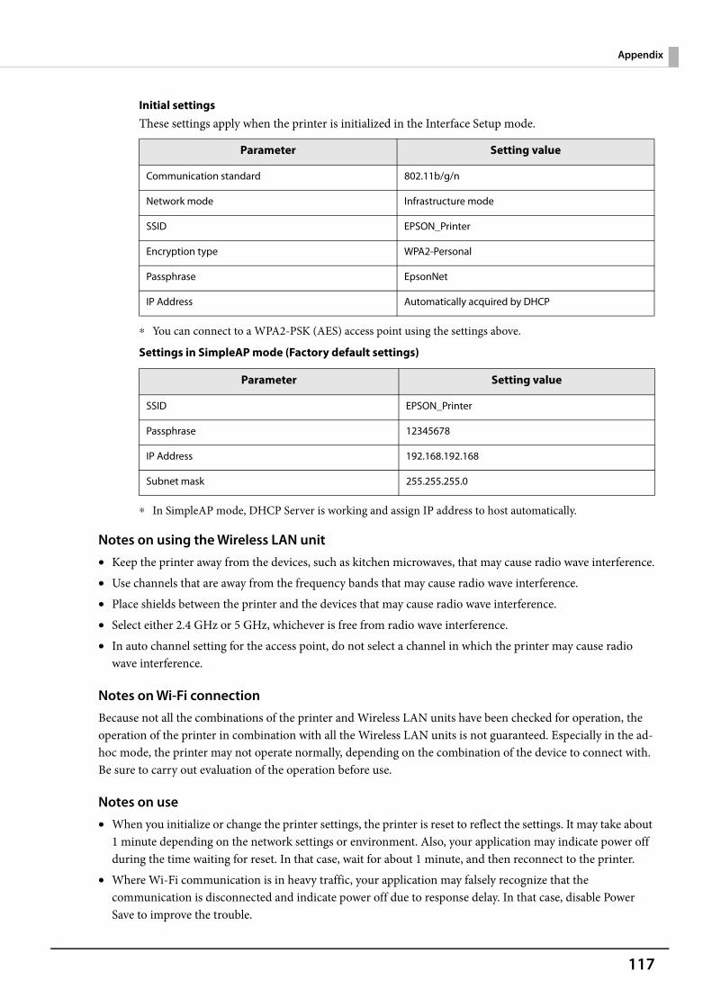
117
Appendix
Initial settingsThese settings apply when the printer is initialized in the Interface Setup mode.
∗ You can connect to a WPA2-PSK (AES) access point using the settings above.
Settings in SimpleAP mode (Factory default settings)
∗ In SimpleAP mode, DHCP Server is working and assign IP address to host automatically.
Notes on using the Wireless LAN unit• Keep the printer away from the devices, such as kitchen microwaves, that may cause radio wave interference.• Use channels that are away from the frequency bands that may cause radio wave interference.• Place shields between the printer and the devices that may cause radio wave interference.• Select either 2.4 GHz or 5 GHz, whichever is free from radio wave interference.• In auto channel setting for the access point, do not select a channel in which the printer may cause radio
wave interference.
Notes on Wi-Fi connectionBecause not all the combinations of the printer and Wireless LAN units have been checked for operation, the operation of the printer in combination with all the Wireless LAN units is not guaranteed. Especially in the ad-hoc mode, the printer may not operate normally, depending on the combination of the device to connect with. Be sure to carry out evaluation of the operation before use.
Notes on use• When you initialize or change the printer settings, the printer is reset to reflect the settings. It may take about
1 minute depending on the network settings or environment. Also, your application may indicate power off during the time waiting for reset. In that case, wait for about 1 minute, and then reconnect to the printer.
• Where Wi-Fi communication is in heavy traffic, your application may falsely recognize that the communication is disconnected and indicate power off due to response delay. In that case, disable Power Save to improve the trouble.
Parameter Setting value
Communication standard 802.11b/g/n
Network mode Infrastructure mode
SSID EPSON_Printer
Encryption type WPA2-Personal
Passphrase EpsonNet
IP Address Automatically acquired by DHCP
Parameter Setting value
SSID EPSON_Printer
Passphrase 12345678
IP Address 192.168.192.168
Subnet mask 255.255.255.0
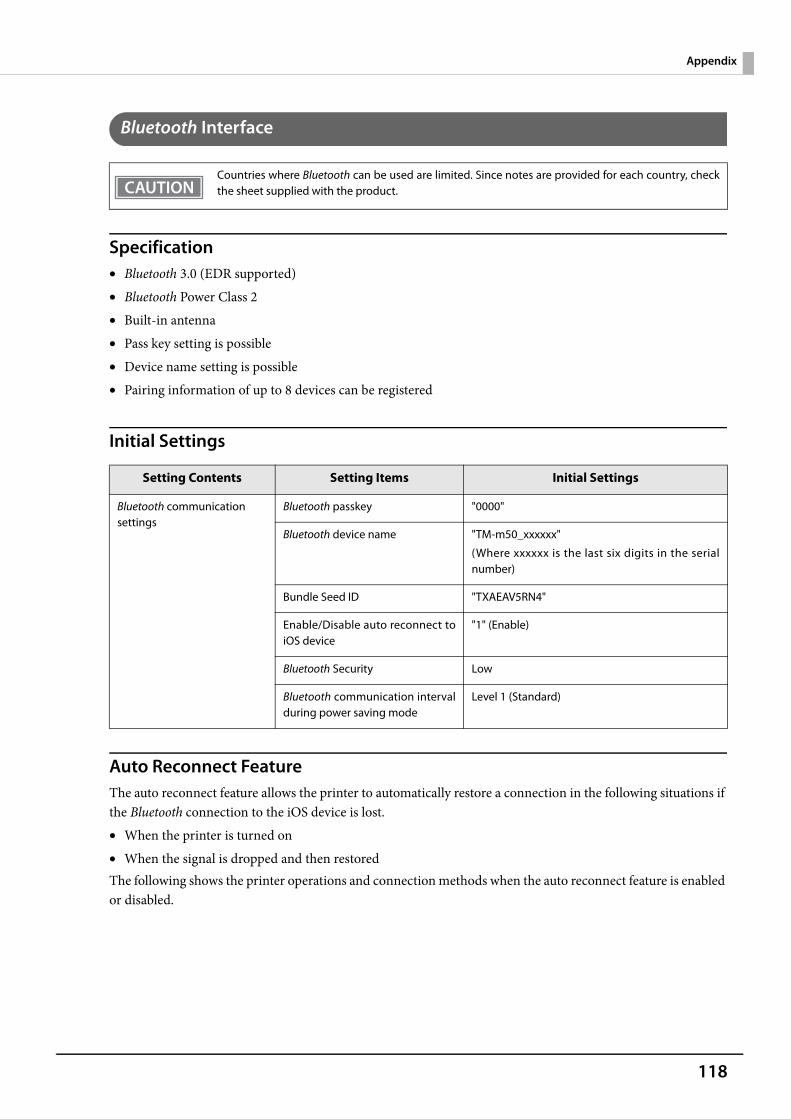
118
Appendix
Bluetooth Interface
Specification• Bluetooth 3.0 (EDR supported)• Bluetooth Power Class 2• Built-in antenna• Pass key setting is possible• Device name setting is possible• Pairing information of up to 8 devices can be registered
Initial Settings
Auto Reconnect FeatureThe auto reconnect feature allows the printer to automatically restore a connection in the following situations if the Bluetooth connection to the iOS device is lost.• When the printer is turned on• When the signal is dropped and then restoredThe following shows the printer operations and connection methods when the auto reconnect feature is enabled or disabled.
Countries where Bluetooth can be used are limited. Since notes are provided for each country, checkthe sheet supplied with the product.
Setting Contents Setting Items Initial Settings
Bluetooth communication settings
Bluetooth passkey "0000"
Bluetooth device name "TM-m50_xxxxxx"
(Where xxxxxx is the last six digits in the serialnumber)
Bundle Seed ID "TXAEAV5RN4"
Enable/Disable auto reconnect toiOS device
"1" (Enable)
Bluetooth Security Low
Bluetooth communication intervalduring power saving mode
Level 1 (Standard)
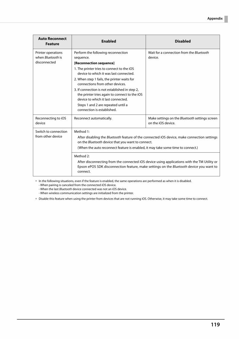
119
Appendix
∗ In the following situations, even if the feature is enabled, the same operations are performed as when it is disabled.- When pairing is canceled from the connected iOS device.- When the last Bluetooth device connected was not an iOS device.- When wireless communication settings are initialized from the printer.
∗ Disable this feature when using the printer from devices that are not running iOS. Otherwise, it may take some time to connect.
Auto ReconnectFeature
Enabled Disabled
Printer operations when Bluetooth is disconnected
Perform the following reconnection sequence.
[Reconnection sequence]
1. The printer tries to connect to the iOS device to which it was last connected.
2. When step 1 fails, the printer waits for connections from other devices.
3. If connection is not established in step 2, the printer tries again to connect to the iOS device to which it last connected.
Steps 1 and 2 are repeated until a connection is established.
Wait for a connection from the Bluetooth device.
Reconnecting to iOS device
Reconnect automatically. Make settings on the Bluetooth settings screenon the iOS device.
Switch to connection from other device
Method 1:
After disabling the Bluetooth feature of the connected iOS device, make connection settingson the Bluetooth device that you want to connect.
(When the auto reconnect feature is enabled, it may take some time to connect.)
Method 2:
After disconnecting from the connected iOS device using applications with the TM Utility orEpson ePOS SDK disconnection feature, make settings on the Bluetooth device you want toconnect.
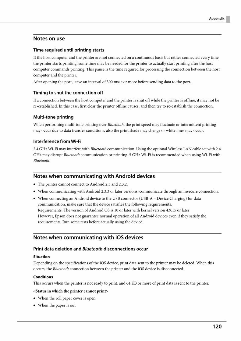
120
Appendix
Notes on use
Time required until printing startsIf the host computer and the printer are not connected on a continuous basis but rather connected every time the printer starts printing, some time may be needed for the printer to actually start printing after the host computer commands printing. This pause is the time required for processing the connection between the host computer and the printer.After opening the port, leave an interval of 300 msec or more before sending data to the port.
Timing to shut the connection offIf a connection between the host computer and the printer is shut off while the printer is offline, it may not be re-established. In this case, first clear the printer offline causes, and then try to re-establish the connection.
Multi-tone printingWhen performing multi-tone printing over Bluetooth, the print speed may fluctuate or intermittent printing may occur due to data transfer conditions, also the print shade may change or white lines may occur.
Interference from Wi-Fi2.4 GHz Wi-Fi may interfere with Bluetooth communication. Using the optional Wireless LAN cable set with 2.4 GHz may disrupt Bluetooth communication or printing. 5 GHz Wi-Fi is recommended when using Wi-Fi with Bluetooth.
Notes when communicating with Android devices• The printer cannot connect to Android 2.3 and 2.3.2.• When communicating with Android 2.3.3 or later versions, communicate through an insecure connection. • When connecting an Android device to the USB connector (USB-A – Device Charging) for data
communication, make sure that the device satisfies the following requirements.Requirements: The version of Android OS is 10 or later with kernel version 4.9.15 or laterHowever, Epson does not guarantee normal operation of all Android devices even if they satisfy the requirements. Run some tests before actually using the device.
Notes when communicating with iOS devices
Print data deletion and Bluetooth disconnections occur
SituationDepending on the specifications of the iOS device, print data sent to the printer may be deleted. When this occurs, the Bluetooth connection between the printer and the iOS device is disconnected.
ConditionsThis occurs when the printer is not ready to print, and 64 KB or more of print data is sent to the printer.
<Status in which the printer cannot print>• When the roll paper cover is open• When the paper is out
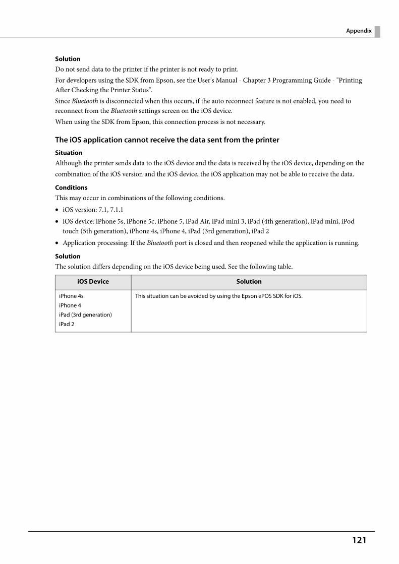
121
Appendix
SolutionDo not send data to the printer if the printer is not ready to print.For developers using the SDK from Epson, see the User's Manual - Chapter 3 Programming Guide - "Printing After Checking the Printer Status".Since Bluetooth is disconnected when this occurs, if the auto reconnect feature is not enabled, you need to reconnect from the Bluetooth settings screen on the iOS device.When using the SDK from Epson, this connection process is not necessary.
The iOS application cannot receive the data sent from the printer
SituationAlthough the printer sends data to the iOS device and the data is received by the iOS device, depending on thecombination of the iOS version and the iOS device, the iOS application may not be able to receive the data.
ConditionsThis may occur in combinations of the following conditions.• iOS version: 7.1, 7.1.1• iOS device: iPhone 5s, iPhone 5c, iPhone 5, iPad Air, iPad mini 3, iPad (4th generation), iPad mini, iPod
touch (5th generation), iPhone 4s, iPhone 4, iPad (3rd generation), iPad 2• Application processing: If the Bluetooth port is closed and then reopened while the application is running.
SolutionThe solution differs depending on the iOS device being used. See the following table.
iOS Device Solution
iPhone 4s
iPhone 4
iPad (3rd generation)
iPad 2
This situation can be avoided by using the Epson ePOS SDK for iOS.
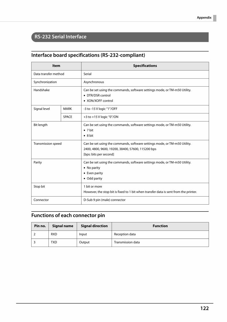
122
Appendix
RS-232 Serial Interface
Interface board specifications (RS-232-compliant)
Functions of each connector pin
Item Specifications
Data transfer method Serial
Synchronization Asynchronous
Handshake Can be set using the commands, software settings mode, or TM-m50 Utility.
• DTR/DSR control
• XON/XOFF control
Signal level MARK -3 to -15 V logic “1”/OFF
SPACE +3 to +15 V logic “0”/ON
Bit length Can be set using the commands, software settings mode, or TM-m50 Utility.
• 7 bit
• 8 bit
Transmission speed Can be set using the commands, software settings mode, or TM-m50 Utility.
2400, 4800, 9600, 19200, 38400, 57600, 115200 bps
[bps: bits per second]
Parity Can be set using the commands, software settings mode, or TM-m50 Utility.
• No parity
• Even parity
• Odd parity
Stop bit 1 bit or more
However, the stop bit is fixed to 1 bit when transfer data is sent from the printer.
Connector D-Sub 9 pin (male) connector
Pin no. Signal name Signal direction Function
2 RXD Input Reception data
3 TXD Output Transmission data
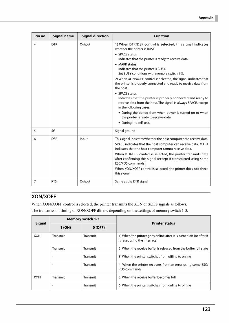
123
Appendix
XON/XOFFWhen XON/XOFF control is selected, the printer transmits the XON or XOFF signals as follows.The transmission timing of XON/XOFF differs, depending on the settings of memory switch 1-3.
4 DTR Output 1) When DTR/DSR control is selected, this signal indicateswhether the printer is BUSY.
• SPACE statusIndicates that the printer is ready to receive data.
• MARK statusIndicates that the printer is BUSY.Set BUSY conditions with memory switch 1-3.
2) When XON/XOFF control is selected, the signal indicates thatthe printer is properly connected and ready to receive data fromthe host.
• SPACE statusIndicates that the printer is properly connected and ready toreceive data from the host. The signal is always SPACE, exceptin the following cases:
• During the period from when power is turned on to whenthe printer is ready to receive data.
• During the self-test.
5 SG - Signal ground
6 DSR Input This signal indicates whether the host computer can receive data.
SPACE indicates that the host computer can receive data. MARKindicates that the host computer cannot receive data.
When DTR/DSR control is selected, the printer transmits dataafter confirming this signal (except if transmitted using someESC/POS commands).
When XON/XOFF control is selected, the printer does not checkthis signal.
7 RTS Output Same as the DTR signal
SignalMemory switch 1-3
Printer status1 (ON) 0 (OFF)
XON Transmit Transmit 1) When the printer goes online after it is turned on (or after itis reset using the interface)
Transmit Transmit 2) When the receive buffer is released from the buffer full state
- Transmit 3) When the printer switches from offline to online
- Transmit 4) When the printer recovers from an error using some ESC/POS commands
XOFF Transmit Transmit 5) When the receive buffer becomes full
- Transmit 6) When the printer switches from online to offline
Pin no. Signal name Signal direction Function
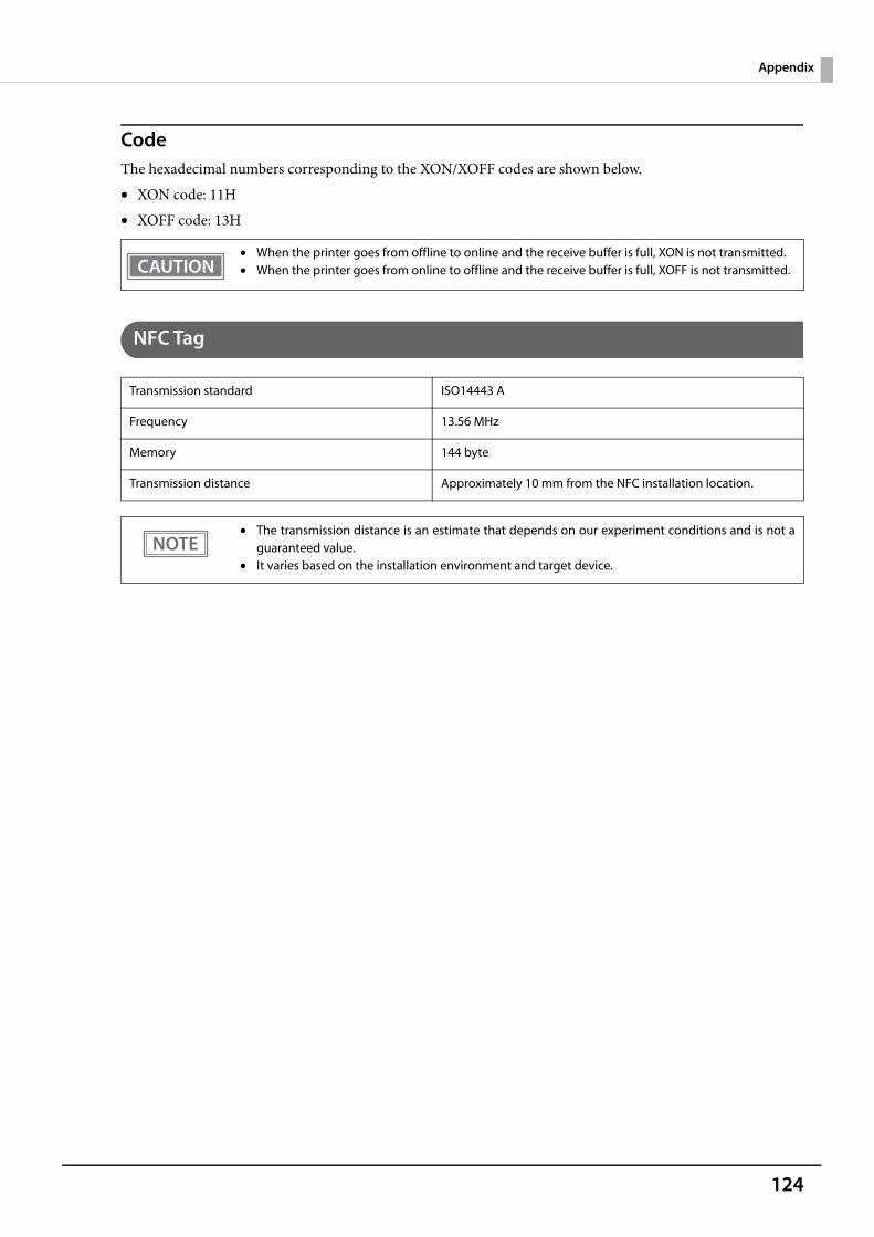
124
Appendix
CodeThe hexadecimal numbers corresponding to the XON/XOFF codes are shown below.• XON code: 11H• XOFF code: 13H
NFC Tag
• When the printer goes from offline to online and the receive buffer is full, XON is not transmitted.• When the printer goes from online to offline and the receive buffer is full, XOFF is not transmitted.
Transmission standard ISO14443 A
Frequency 13.56 MHz
Memory 144 byte
Transmission distance Approximately 10 mm from the NFC installation location.
• The transmission distance is an estimate that depends on our experiment conditions and is not aguaranteed value.
• It varies based on the installation environment and target device.
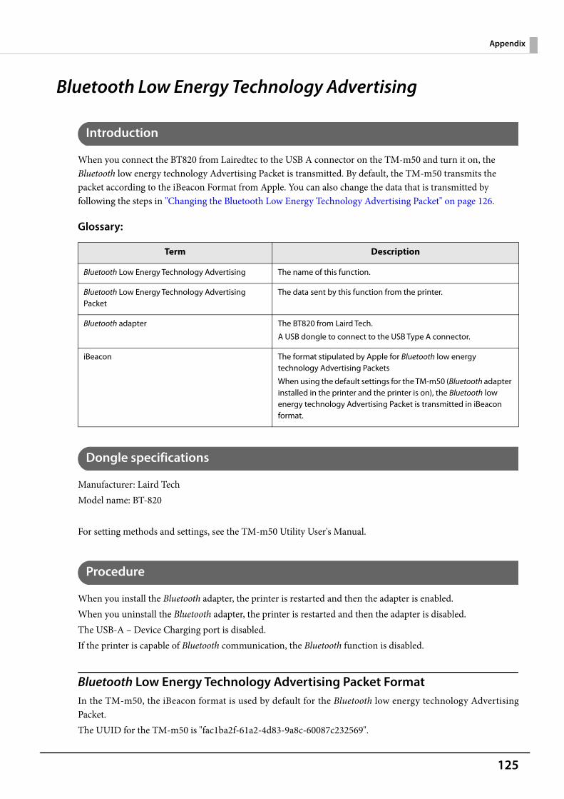
125
Appendix
Bluetooth Low Energy Technology Advertising
Introduction
When you connect the BT820 from Lairedtec to the USB A connector on the TM-m50 and turn it on, the Bluetooth low energy technology Advertising Packet is transmitted. By default, the TM-m50 transmits the packet according to the iBeacon Format from Apple. You can also change the data that is transmitted by following the steps in "Changing the Bluetooth Low Energy Technology Advertising Packet" on page 126.
Glossary:
Dongle specifications
Manufacturer: Laird TechModel name: BT-820
For setting methods and settings, see the TM-m50 Utility User's Manual.
Procedure
When you install the Bluetooth adapter, the printer is restarted and then the adapter is enabled.When you uninstall the Bluetooth adapter, the printer is restarted and then the adapter is disabled.The USB-A – Device Charging port is disabled.If the printer is capable of Bluetooth communication, the Bluetooth function is disabled.
Bluetooth Low Energy Technology Advertising Packet FormatIn the TM-m50, the iBeacon format is used by default for the Bluetooth low energy technology AdvertisingPacket.The UUID for the TM-m50 is "fac1ba2f-61a2-4d83-9a8c-60087c232569".
Term Description
Bluetooth Low Energy Technology Advertising The name of this function.
Bluetooth Low Energy Technology Advertising Packet
The data sent by this function from the printer.
Bluetooth adapter The BT820 from Laird Tech.
A USB dongle to connect to the USB Type A connector.
iBeacon The format stipulated by Apple for Bluetooth low energy technology Advertising Packets
When using the default settings for the TM-m50 (Bluetooth adapter installed in the printer and the printer is on), the Bluetooth low energy technology Advertising Packet is transmitted in iBeacon format.
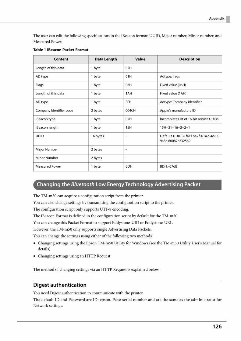
126
Appendix
The user can edit the following specifications in the iBeacon format: UUID, Major number, Minor number, andMeasured Power.
Table 1 iBeacon Packet Format
Changing the Bluetooth Low Energy Technology Advertising Packet
The TM-m50 can acquire a configuration script from the printer.You can also change settings by transmitting the configuration script to the printer.The configuration script only supports UTF-8 encoding.The iBeacon Format is defined in the configuration script by default for the TM-m50.You can change this Packet Format to support Eddystone-UID or Eddystone-URL.However, the TM-m50 only supports single Advertising Data Packets.You can change the settings using either of the following two methods.• Changing settings using the Epson TM-m50 Utility for Windows (see the TM-m50 Utility User's Manual for
details)• Changing settings using an HTTP Request
The method of changing settings via an HTTP Request is explained below.
Digest authenticationYou need Digest authentication to communicate with the printer.The default ID and Password are ID: epson, Pass: serial number and are the same as the administrator forNetwork settings.
Content Data Length Value Description
Length of this data 1 byte 02H
AD type 1 byte 01H Adtype: flags
Flags 1 byte 06H Fixed value (06H)
Length of this data 1 byte 1AH Fixed value (1AH)
AD type 1 byte FFH Adtype: Company identifier
Company Identifier code 2 bytes 004CH Apple’s manufacture ID
iBeacon type 1 byte 02H Incomplete List of 16-bit service UUIDs
iBeacon length 1 byte 15H 15H=21=16+2+2+1
UUID 16 bytes - Default UUID = fac1ba2f-61a2-4d83-9a8c-60087c232569
Major Number 2 bytes -
Minor Number 2 bytes -
Measured Power 1 byte BDH BDH: -67dB
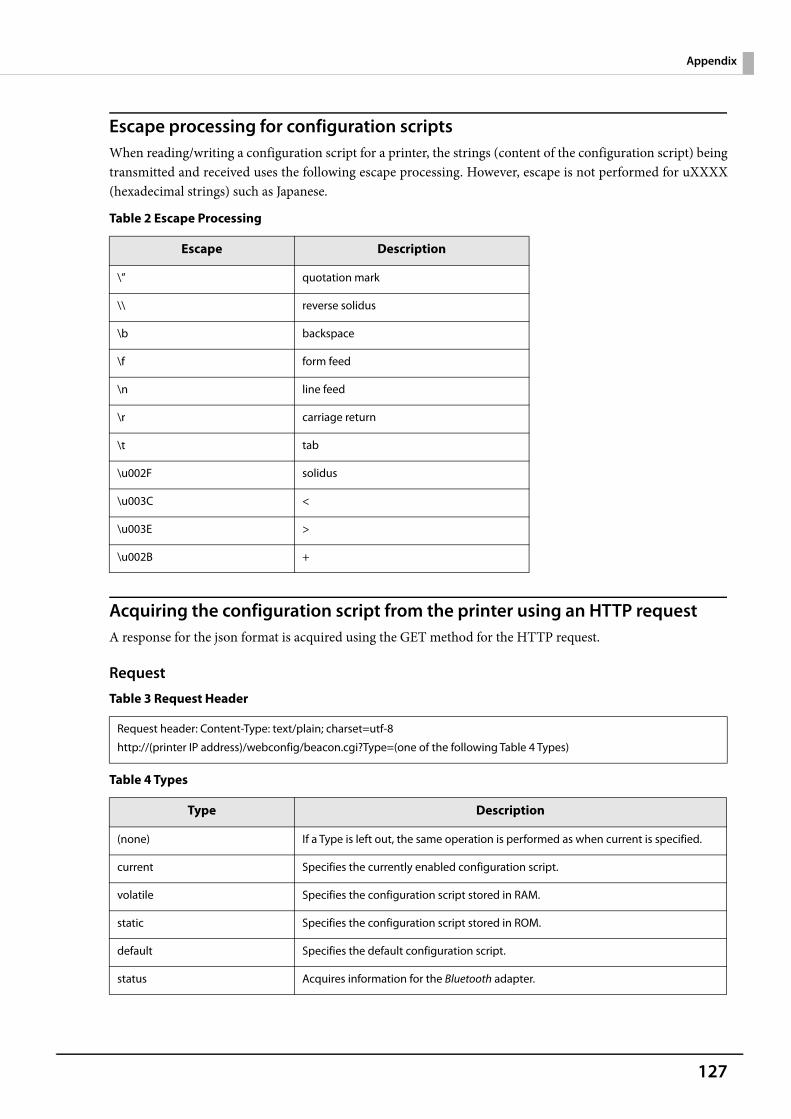
127
Appendix
Escape processing for configuration scriptsWhen reading/writing a configuration script for a printer, the strings (content of the configuration script) beingtransmitted and received uses the following escape processing. However, escape is not performed for uXXXX(hexadecimal strings) such as Japanese.
Table 2 Escape Processing
Acquiring the configuration script from the printer using an HTTP requestA response for the json format is acquired using the GET method for the HTTP request.
Request
Table 3 Request Header
Table 4 Types
Escape Description
\” quotation mark
\\ reverse solidus
\b backspace
\f form feed
\n line feed
\r carriage return
\t tab
\u002F solidus
\u003C <
\u003E >
\u002B +
Request header: Content-Type: text/plain; charset=utf-8
http://(printer IP address)/webconfig/beacon.cgi?Type=(one of the following Table 4 Types)
Type Description
(none) If a Type is left out, the same operation is performed as when current is specified.
current Specifies the currently enabled configuration script.
volatile Specifies the configuration script stored in RAM.
static Specifies the configuration script stored in ROM.
default Specifies the default configuration script.
status Acquires information for the Bluetooth adapter.
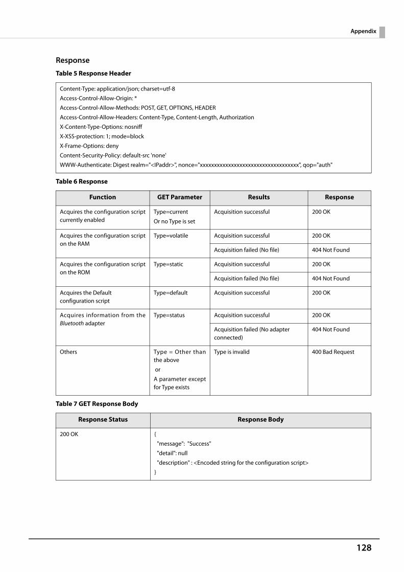
128
Appendix
Response
Table 5 Response Header
Table 6 Response
Table 7 GET Response Body
Content-Type: application/json; charset=utf-8
Access-Control-Allow-Origin: *
Access-Control-Allow-Methods: POST, GET, OPTIONS, HEADER
Access-Control-Allow-Headers: Content-Type, Content-Length, Authorization
X-Content-Type-Options: nosniff
X-XSS-protection: 1; mode=block
X-Frame-Options: deny
Content-Security-Policy: default-src 'none'
WWW-Authenticate: Digest realm="<IPaddr>", nonce="xxxxxxxxxxxxxxxxxxxxxxxxxxxxxxxxxxx", qop="auth"
Function GET Parameter Results Response
Acquires the configuration scriptcurrently enabled
Type=current
Or no Type is set
Acquisition successful 200 OK
Acquires the configuration scripton the RAM
Type=volatile Acquisition successful 200 OK
Acquisition failed (No file) 404 Not Found
Acquires the configuration scripton the ROM
Type=static Acquisition successful 200 OK
Acquisition failed (No file) 404 Not Found
Acquires the Default configuration script
Type=default Acquisition successful 200 OK
Acquires information from theBluetooth adapter
Type=status Acquisition successful 200 OK
Acquisition failed (No adapter connected)
404 Not Found
Others Type = Other thanthe above
or
A parameter exceptfor Type exists
Type is invalid 400 Bad Request
Response Status Response Body
200 OK {
"message": "Success"
"detail": null
"description" : <Encoded string for the configuration script>
}
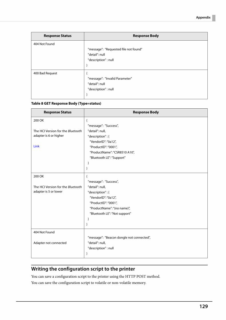
129
Appendix
Table 8 GET Response Body (Type=status)
Writing the configuration script to the printerYou can save a configuration script to the printer using the HTTP POST method.You can save the configuration script to volatile or non-volatile memory.
404 Not Found
"message": "Requested file not found"
"detail": null
"description" : null
}
400 Bad Request {
"message": "Invalid Parameter"
"detail": null
"description" : null
}
Response Status Response Body
200 OK
The HCI Version for the Bluetoothadapter is 6 or higher
Link
{
"message": "Success",
"detail": null,
"description" : {
“VendorID”: “0a12”,
“ProductID”: “0001”,
“ProductName”: “CSR8510 A10”,
“Bluetooth LE”: “Support”
}
}
200 OK
The HCI Version for the Bluetoothadapter is 5 or lower
{
"message": "Success",
"detail": null,
"description" : {
“VendorID”: “0a12”,
“ProductID”: “0001”,
“ProductName”: “(no name)”,
“Bluetooth LE”: “Not support”
}
}
404 Not Found
Adapter not connected
"message": "Beacon dongle not connected",
"detail": null,
"description" : null
}
Response Status Response Body
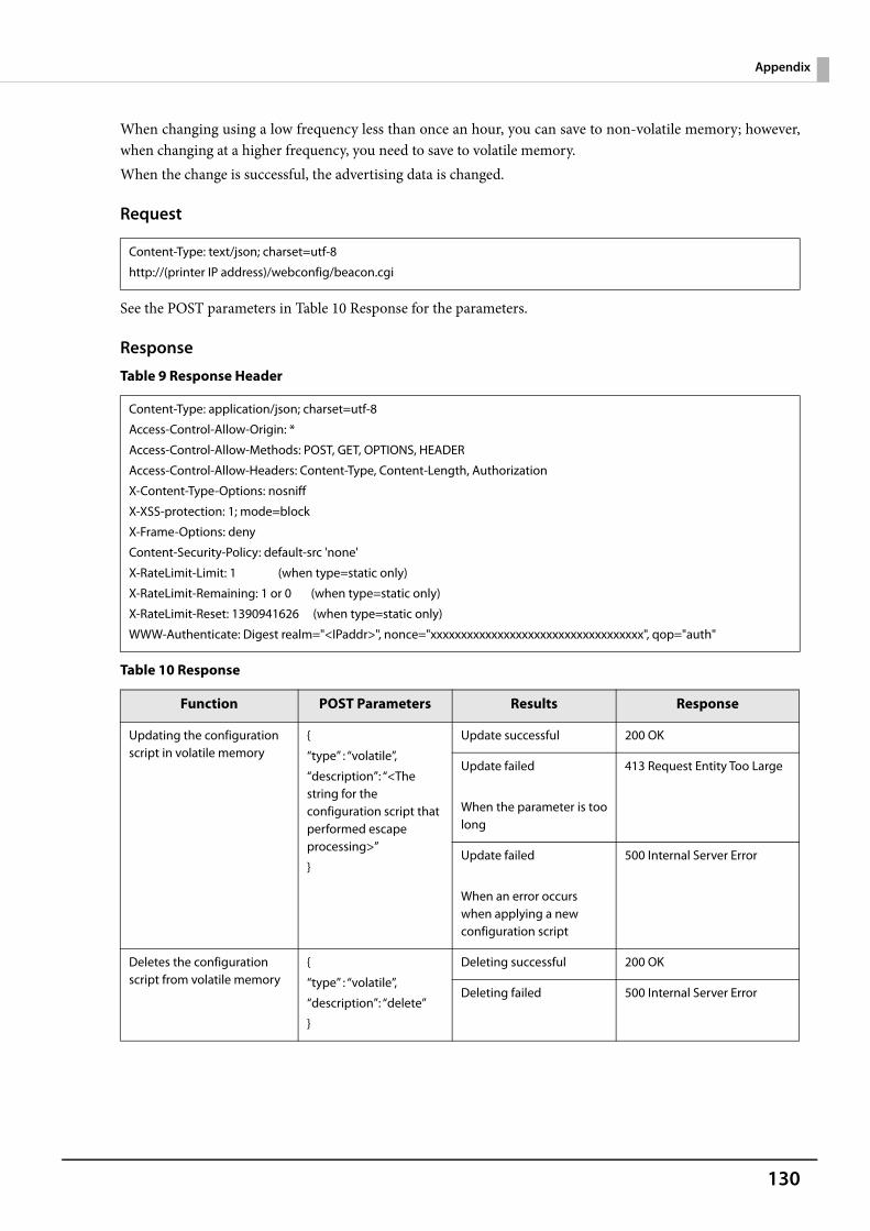
130
Appendix
When changing using a low frequency less than once an hour, you can save to non-volatile memory; however,when changing at a higher frequency, you need to save to volatile memory.When the change is successful, the advertising data is changed.
Request
See the POST parameters in Table 10 Response for the parameters.
Response
Table 9 Response Header
Table 10 Response
Content-Type: text/json; charset=utf-8
http://(printer IP address)/webconfig/beacon.cgi
Content-Type: application/json; charset=utf-8
Access-Control-Allow-Origin: *
Access-Control-Allow-Methods: POST, GET, OPTIONS, HEADER
Access-Control-Allow-Headers: Content-Type, Content-Length, Authorization
X-Content-Type-Options: nosniff
X-XSS-protection: 1; mode=block
X-Frame-Options: deny
Content-Security-Policy: default-src 'none'
X-RateLimit-Limit: 1 (when type=static only)
X-RateLimit-Remaining: 1 or 0 (when type=static only)
X-RateLimit-Reset: 1390941626 (when type=static only)
WWW-Authenticate: Digest realm="<IPaddr>", nonce="xxxxxxxxxxxxxxxxxxxxxxxxxxxxxxxxxxx", qop="auth"
Function POST Parameters Results Response
Updating the configuration script in volatile memory
{
“type” : “volatile”,
“description”: “<The string for the configuration script that performed escape processing>”
}
Update successful 200 OK
Update failed
When the parameter is toolong
413 Request Entity Too Large
Update failed
When an error occurs when applying a new configuration script
500 Internal Server Error
Deletes the configuration script from volatile memory
{
“type” : “volatile”,
“description”: “delete”
}
Deleting successful 200 OK
Deleting failed 500 Internal Server Error
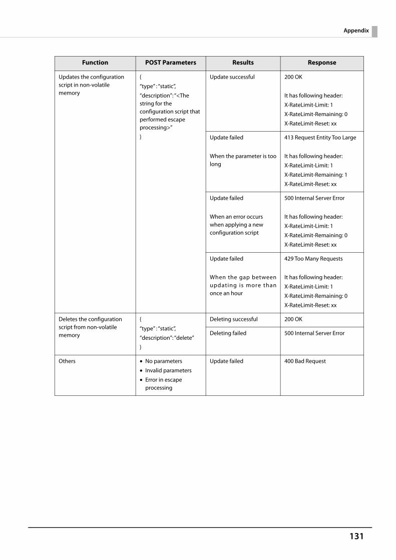
131
Appendix
Updates the configuration script in non-volatile memory
{
“type” : “static”,
“description”: “<The string for the configuration script that performed escape processing>”
}
Update successful 200 OK
It has following header:
X-RateLimit-Limit: 1
X-RateLimit-Remaining: 0
X-RateLimit-Reset: xx
Update failed
When the parameter is toolong
413 Request Entity Too Large
It has following header:
X-RateLimit-Limit: 1
X-RateLimit-Remaining: 1
X-RateLimit-Reset: xx
Update failed
When an error occurs when applying a new configuration script
500 Internal Server Error
It has following header:
X-RateLimit-Limit: 1
X-RateLimit-Remaining: 0
X-RateLimit-Reset: xx
Update failed
When the gap betweenupdating is more thanonce an hour
429 Too Many Requests
It has following header:
X-RateLimit-Limit: 1
X-RateLimit-Remaining: 0
X-RateLimit-Reset: xx
Deletes the configuration script from non-volatile memory
{
“type” : “static”,
“description”: “delete”
}
Deleting successful 200 OK
Deleting failed 500 Internal Server Error
Others • No parameters
• Invalid parameters
• Error in escape processing
Update failed 400 Bad Request
Function POST Parameters Results Response
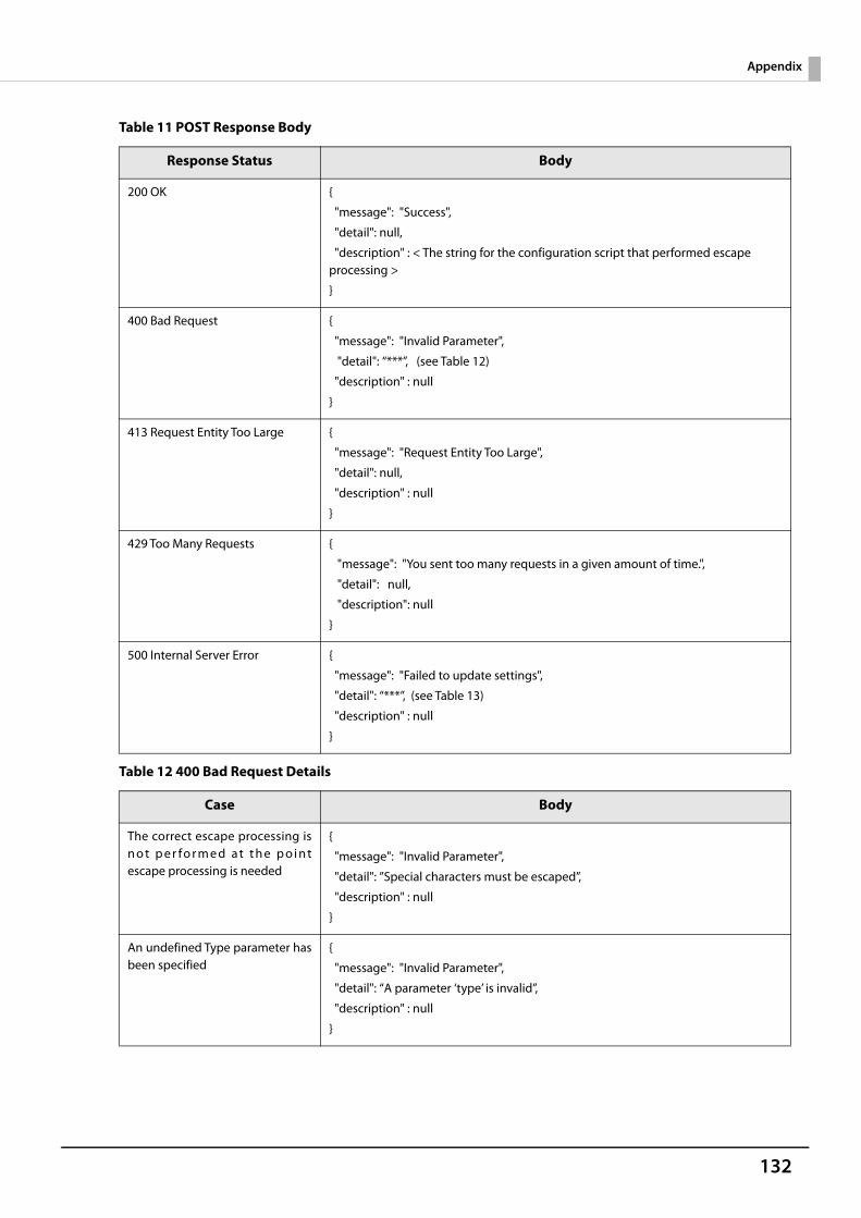
132
Appendix
Table 11 POST Response Body
Table 12 400 Bad Request Details
Response Status Body
200 OK {
"message": "Success",
"detail": null,
"description" : < The string for the configuration script that performed escape processing >
}
400 Bad Request {
"message": "Invalid Parameter",
"detail": “***”, (see Table 12)
"description" : null
}
413 Request Entity Too Large {
"message": "Request Entity Too Large",
"detail": null,
"description" : null
}
429 Too Many Requests {
"message": "You sent too many requests in a given amount of time.",
"detail": null,
"description": null
}
500 Internal Server Error {
"message": "Failed to update settings",
"detail": “***”, (see Table 13)
"description" : null
}
Case Body
The correct escape processing isn o t p e r fo r m e d a t t h e p o i n tescape processing is needed
{
"message": "Invalid Parameter",
"detail": ”Special characters must be escaped”,
"description" : null
}
An undefined Type parameter hasbeen specified
{
"message": "Invalid Parameter",
"detail": “A parameter ‘type’ is invalid”,
"description" : null
}
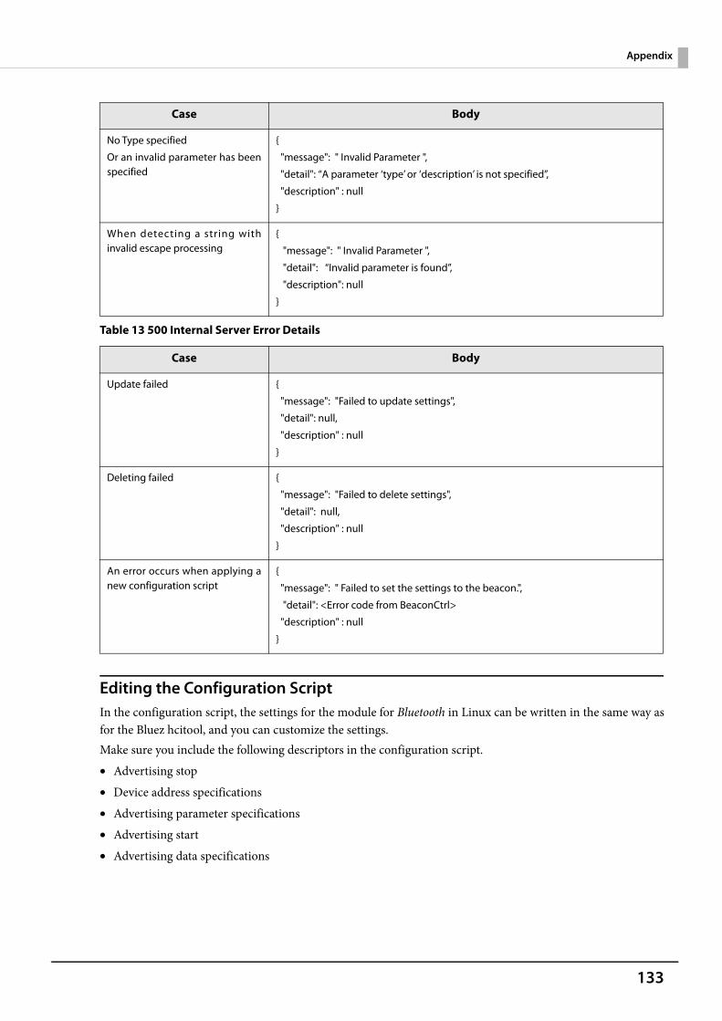
133
Appendix
Table 13 500 Internal Server Error Details
Editing the Configuration ScriptIn the configuration script, the settings for the module for Bluetooth in Linux can be written in the same way asfor the Bluez hcitool, and you can customize the settings.Make sure you include the following descriptors in the configuration script.• Advertising stop• Device address specifications• Advertising parameter specifications• Advertising start• Advertising data specifications
No Type specified
Or an invalid parameter has beenspecified
{
"message": " Invalid Parameter ",
"detail": “A parameter ‘type’ or ‘description’ is not specified”,
"description" : null
}
When detecting a string withinvalid escape processing
{
"message": " Invalid Parameter ",
"detail": “Invalid parameter is found”,
"description": null
}
Case Body
Update failed {
"message": "Failed to update settings",
"detail": null,
"description" : null
}
Deleting failed {
"message": "Failed to delete settings",
"detail": null,
"description" : null
}
An error occurs when applying anew configuration script
{
"message": " Failed to set the settings to the beacon.",
"detail": <Error code from BeaconCtrl>
"description" : null
}
Case Body
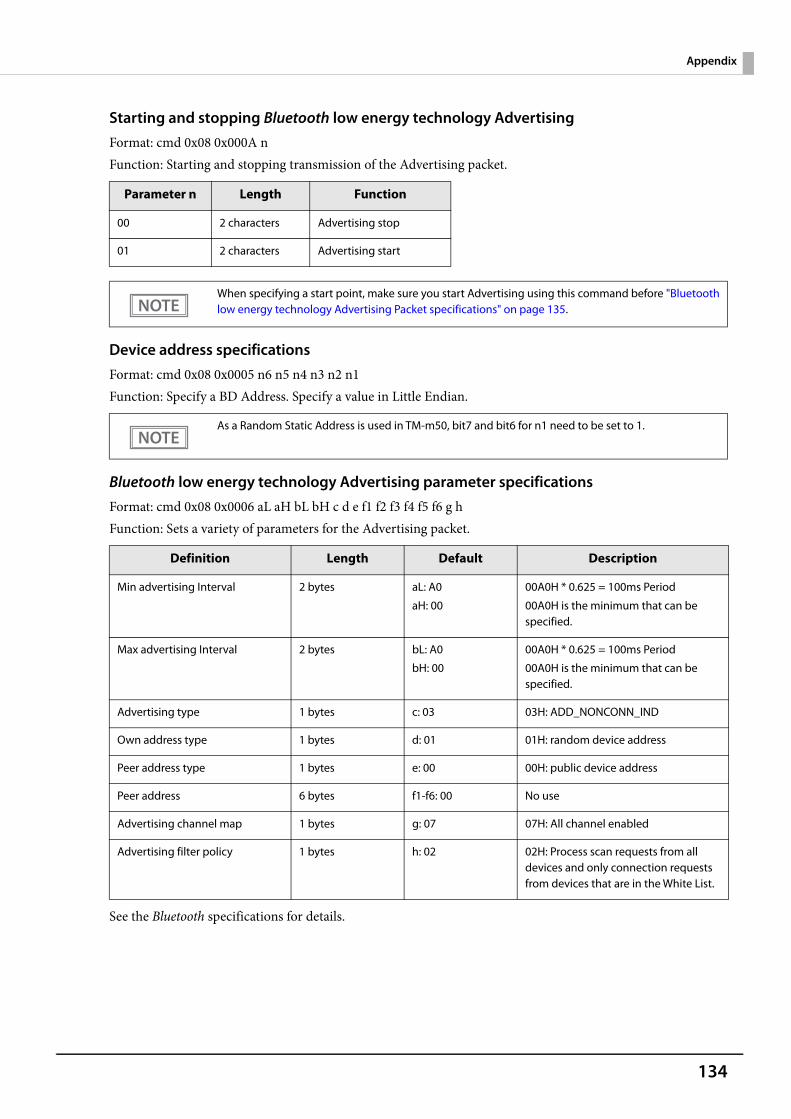
134
Appendix
Starting and stopping Bluetooth low energy technology AdvertisingFormat: cmd 0x08 0x000A nFunction: Starting and stopping transmission of the Advertising packet.
Device address specificationsFormat: cmd 0x08 0x0005 n6 n5 n4 n3 n2 n1Function: Specify a BD Address. Specify a value in Little Endian.
Bluetooth low energy technology Advertising parameter specificationsFormat: cmd 0x08 0x0006 aL aH bL bH c d e f1 f2 f3 f4 f5 f6 g hFunction: Sets a variety of parameters for the Advertising packet.
See the Bluetooth specifications for details.
Parameter n Length Function
00 2 characters Advertising stop
01 2 characters Advertising start
When specifying a start point, make sure you start Advertising using this command before "Bluetoothlow energy technology Advertising Packet specifications" on page 135.
As a Random Static Address is used in TM-m50, bit7 and bit6 for n1 need to be set to 1.
Definition Length Default Description
Min advertising Interval 2 bytes aL: A0
aH: 00
00A0H * 0.625 = 100ms Period
00A0H is the minimum that can be specified.
Max advertising Interval 2 bytes bL: A0
bH: 00
00A0H * 0.625 = 100ms Period
00A0H is the minimum that can be specified.
Advertising type 1 bytes c: 03 03H: ADD_NONCONN_IND
Own address type 1 bytes d: 01 01H: random device address
Peer address type 1 bytes e: 00 00H: public device address
Peer address 6 bytes f1-f6: 00 No use
Advertising channel map 1 bytes g: 07 07H: All channel enabled
Advertising filter policy 1 bytes h: 02 02H: Process scan requests from all devices and only connection requests from devices that are in the White List.
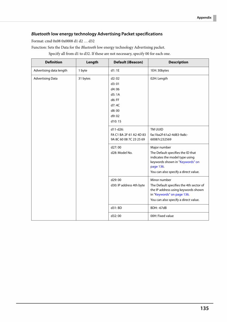
135
Appendix
Bluetooth low energy technology Advertising Packet specificationsFormat: cmd 0x08 0x0008 d1 d2 … d32Function: Sets the Data for the Bluetooth low energy technology Advertising packet.
Specify all from d1 to d32. If these are not necessary, specify 00 for each one.
Definition Length Default (iBeacon) Description
Advertising data length 1 byte d1: 1E 1EH: 30bytes
Advertising Data 31 bytes d2: 02
d3: 01
d4: 06
d5: 1A
d6: FF
d7: 4C
d8: 00
d9: 02
d10: 15
02H: Length
d11-d26:
FA C1 BA 2F 61 A2 4D 839A 8C 60 08 7C 23 25 69
TM UUID
fac1ba2f-61a2-4d83-9a8c-60087c232569
d27: 00
d28: Model No.
Major number
The Default specifies the ID that indicates the model type using keywords shown in "Keywords" on page 136.
You can also specify a direct value.
d29: 00
d30: IP address 4th byte
Minor number
The Default specifies the 4th sector of the IP address using keywords shown in "Keywords" on page 136.
You can also specify a direct value.
d31: BD BDH: -67dB
d32: 00 00H: Fixed value
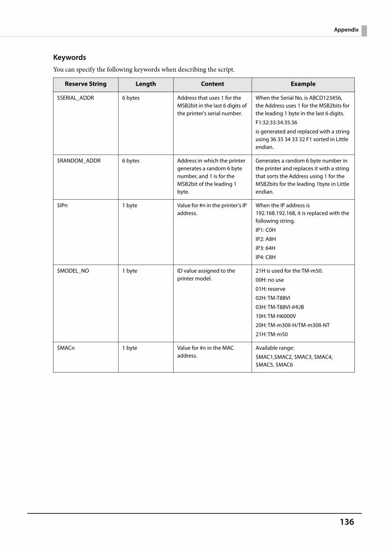
136
Appendix
KeywordsYou can specify the following keywords when describing the script.
Reserve String Length Content Example
$SERIAL_ADDR 6 bytes Address that uses 1 for the MSB2bit in the last 6 digits of the printer's serial number.
When the Serial No. is ABCD123456, the Address uses 1 for the MSB2bits for the leading 1 byte in the last 6 digits.
F1:32:33:34:35:36
is generated and replaced with a string using 36 35 34 33 32 F1 sorted in Little endian.
$RANDOM_ADDR 6 bytes Address in which the printer generates a random 6 byte number, and 1 is for the MSB2bit of the leading 1 byte.
Generates a random 6 byte number in the printer and replaces it with a string that sorts the Address using 1 for the MSB2bits for the leading 1byte in Little endian.
$IPn 1 byte Value for #n in the printer's IP address.
When the IP address is 192.168.192.168, it is replaced with the following string.
IP1: C0H
IP2: A8H
IP3: 64H
IP4: C8H
$MODEL_NO 1 byte ID value assigned to the printer model.
21H is used for the TM-m50.
00H: no use
01H: reserve
02H: TM-T88VI
03H: TM-T88VI-iHUB
10H: TM-H6000V
20H: TM-m30II-H/TM-m30II-NT
21H: TM-m50
$MACn 1 byte Value for #n in the MAC address.
Available range:
$MAC1,$MAC2, $MAC3, $MAC4, $MAC5, $MAC6

137
Appendix
Character Code TablesRefer to the following URL regarding the character code table.U www.epson-biz.com/pos/reference/charcode/
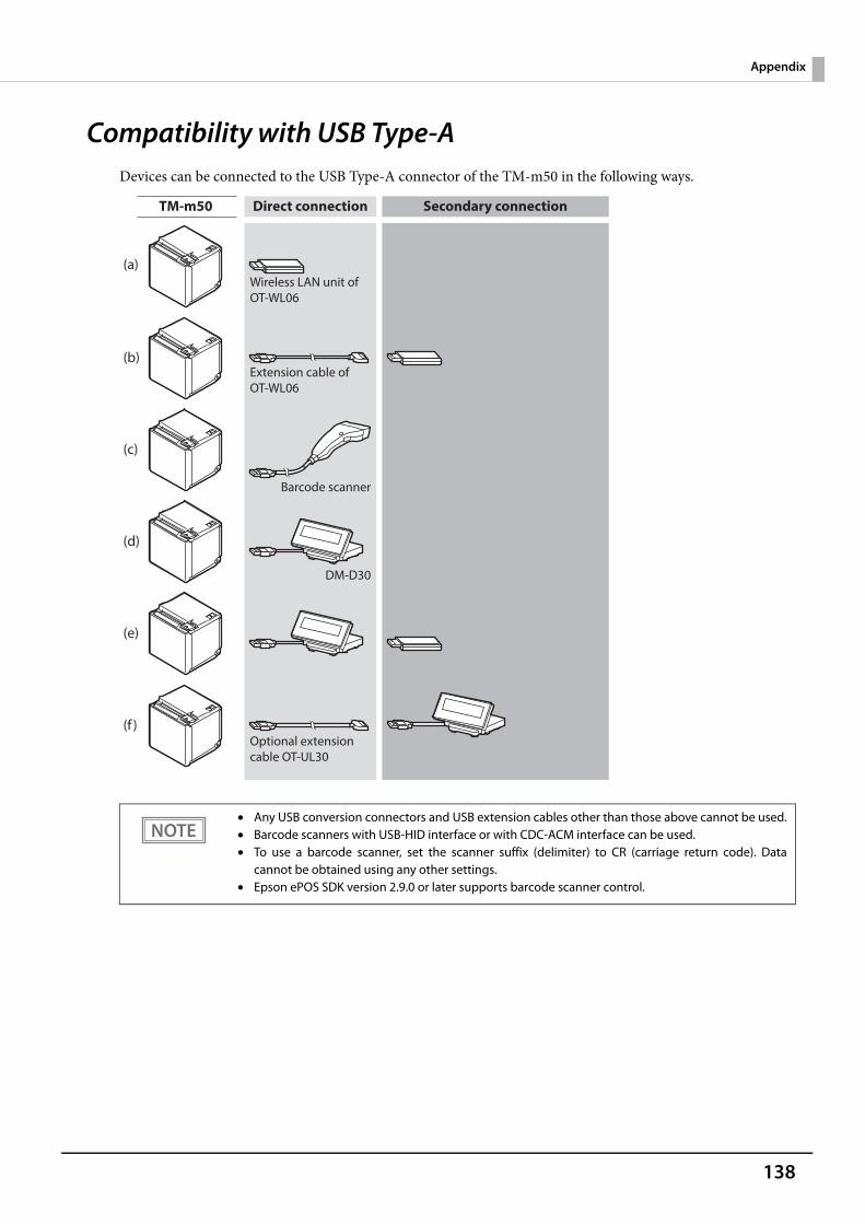
138
Appendix
Compatibility with USB Type-ADevices can be connected to the USB Type-A connector of the TM-m50 in the following ways.
• Any USB conversion connectors and USB extension cables other than those above cannot be used.• Barcode scanners with USB-HID interface or with CDC-ACM interface can be used.• To use a barcode scanner, set the scanner suffix (delimiter) to CR (carriage return code). Data
cannot be obtained using any other settings.• Epson ePOS SDK version 2.9.0 or later supports barcode scanner control.
Secondary connectionDirect connectionTM-m50
Extension cable of OT-WL06
Barcode scanner
DM-D30
Optional extension cable OT-UL30
Wireless LAN unit of OT-WL06
(a)
(b)
(c)
(d)
(e)
(f )