Reference manual FAST TM Winder Tension-controlled
71
L Ä.[zNä 13588972 Technology module FAST Application Software Winder Tension-controlled _ _ _ _ _ _ _ _ _ _ _ _ _ _ _ _ _ _ Reference Manual EN
Transcript of Reference manual FAST TM Winder Tension-controlled

L
Ä.[zNä
1358
8972
Technology module
FAST Application Software
Winder Tension-controlled _ _ _ _ _ _ _ _ _ _ _ _ _ _ _ _ _ _ Reference Manual EN
2 Lenze · Technology module | Winder Tension-controlled · Reference Manual · DMS 7.0 EN · 12/2019 · TD06
_ _ _ _ _ _ _ _ _ _ _ _ _ _ _ _ _ _ _ _ _ _ _ _ _ _ _ _ _ _ _ _ _ _ _ _ _ _ _ _ _ _ _ _ _ _ _ _ _ _ _ _ _ _ _ _ _ _ _ _ _ _ _ _
1 About this documentation _ _ _ _ _ _ _ _ _ _ _ _ _ _ _ _ _ _ _ _ _ _ _ _ _ _ _ _ _ _ _ _ _ _ _ _ _ _ _ 31.1 Document history _ _ _ _ _ _ _ _ _ _ _ _ _ _ _ _ _ _ _ _ _ _ _ _ _ _ _ _ _ _ _ _ _ _ _ _ _ _ _ _ _ _ _ _ 51.2 Conventions used _ _ _ _ _ _ _ _ _ _ _ _ _ _ _ _ _ _ _ _ _ _ _ _ _ _ _ _ _ _ _ _ _ _ _ _ _ _ _ _ _ _ _ _ 61.3 Definition of the notes used _ _ _ _ _ _ _ _ _ _ _ _ _ _ _ _ _ _ _ _ _ _ _ _ _ _ _ _ _ _ _ _ _ _ _ _ _ _ 7
2 Safety instructions _ _ _ _ _ _ _ _ _ _ _ _ _ _ _ _ _ _ _ _ _ _ _ _ _ _ _ _ _ _ _ _ _ _ _ _ _ _ _ _ _ _ _ _ 8
3 Functional description for "Winder Tension-controlled" _ _ _ _ _ _ _ _ _ _ _ _ _ _ _ _ _ _ _ _ _ _ _ 103.1 Overview of the functions _ _ _ _ _ _ _ _ _ _ _ _ _ _ _ _ _ _ _ _ _ _ _ _ _ _ _ _ _ _ _ _ _ _ _ _ _ _ _ _ 123.2 Important notes on how to operate the technology module _ _ _ _ _ _ _ _ _ _ _ _ _ _ _ _ _ _ _ _ _ 133.3 L_TT1P_WinderTensionCtrl[Base/State/High] function block _ _ _ _ _ _ _ _ _ _ _ _ _ _ _ _ _ _ _ _ 15
3.3.1 Inputs and outputs _ _ _ _ _ _ _ _ _ _ _ _ _ _ _ _ _ _ _ _ _ _ _ _ _ _ _ _ _ _ _ _ _ _ _ _ _ _ _ 163.3.2 inputs _ _ _ _ _ _ _ _ _ _ _ _ _ _ _ _ _ _ _ _ _ _ _ _ _ _ _ _ _ _ _ _ _ _ _ _ _ _ _ _ _ _ _ _ _ _ 173.3.3 outputs _ _ _ _ _ _ _ _ _ _ _ _ _ _ _ _ _ _ _ _ _ _ _ _ _ _ _ _ _ _ _ _ _ _ _ _ _ _ _ _ _ _ _ _ _ 213.3.4 Parameter _ _ _ _ _ _ _ _ _ _ _ _ _ _ _ _ _ _ _ _ _ _ _ _ _ _ _ _ _ _ _ _ _ _ _ _ _ _ _ _ _ _ _ 23
3.4 State machine _ _ _ _ _ _ _ _ _ _ _ _ _ _ _ _ _ _ _ _ _ _ _ _ _ _ _ _ _ _ _ _ _ _ _ _ _ _ _ _ _ _ _ _ _ _ 283.5 Signal flow diagrams _ _ _ _ _ _ _ _ _ _ _ _ _ _ _ _ _ _ _ _ _ _ _ _ _ _ _ _ _ _ _ _ _ _ _ _ _ _ _ _ _ _ 30
3.5.1 Structure of the signal flow _ _ _ _ _ _ _ _ _ _ _ _ _ _ _ _ _ _ _ _ _ _ _ _ _ _ _ _ _ _ _ _ _ _ 323.5.2 Structure of the access points _ _ _ _ _ _ _ _ _ _ _ _ _ _ _ _ _ _ _ _ _ _ _ _ _ _ _ _ _ _ _ _ _ 34
3.6 Defining the winding direction (winding/unwinding) _ _ _ _ _ _ _ _ _ _ _ _ _ _ _ _ _ _ _ _ _ _ _ _ 363.7 Automatic detection of the winding direction _ _ _ _ _ _ _ _ _ _ _ _ _ _ _ _ _ _ _ _ _ _ _ _ _ _ _ _ _ 363.8 Defining the material feed to the winder _ _ _ _ _ _ _ _ _ _ _ _ _ _ _ _ _ _ _ _ _ _ _ _ _ _ _ _ _ _ _ 373.9 Master value source for diameter calculation _ _ _ _ _ _ _ _ _ _ _ _ _ _ _ _ _ _ _ _ _ _ _ _ _ _ _ _ _ 383.10 Speed feedforward control _ _ _ _ _ _ _ _ _ _ _ _ _ _ _ _ _ _ _ _ _ _ _ _ _ _ _ _ _ _ _ _ _ _ _ _ _ _ _ 383.11 Calculation of the diameter _ _ _ _ _ _ _ _ _ _ _ _ _ _ _ _ _ _ _ _ _ _ _ _ _ _ _ _ _ _ _ _ _ _ _ _ _ _ _ 393.12 Holding the diameter _ _ _ _ _ _ _ _ _ _ _ _ _ _ _ _ _ _ _ _ _ _ _ _ _ _ _ _ _ _ _ _ _ _ _ _ _ _ _ _ _ _ 403.13 Defining the diameter / signal from the diameter sensor _ _ _ _ _ _ _ _ _ _ _ _ _ _ _ _ _ _ _ _ _ _ 413.14 Material length counter _ _ _ _ _ _ _ _ _ _ _ _ _ _ _ _ _ _ _ _ _ _ _ _ _ _ _ _ _ _ _ _ _ _ _ _ _ _ _ _ _ 423.15 Sources for the material length counting _ _ _ _ _ _ _ _ _ _ _ _ _ _ _ _ _ _ _ _ _ _ _ _ _ _ _ _ _ _ _ 43
3.15.1 Source: "lrSetLineVel" input _ _ _ _ _ _ _ _ _ _ _ _ _ _ _ _ _ _ _ _ _ _ _ _ _ _ _ _ _ _ _ _ _ _ 433.15.2 Source: "lrSetLineVelDiamCalc" input _ _ _ _ _ _ _ _ _ _ _ _ _ _ _ _ _ _ _ _ _ _ _ _ _ _ _ _ 433.15.3 Source: "MaterialCounterAxis" input (reference axis) _ _ _ _ _ _ _ _ _ _ _ _ _ _ _ _ _ _ _ _ 44
3.16 Manual jog (jogging) _ _ _ _ _ _ _ _ _ _ _ _ _ _ _ _ _ _ _ _ _ _ _ _ _ _ _ _ _ _ _ _ _ _ _ _ _ _ _ _ _ _ 453.17 Synchronisation to the line velocity _ _ _ _ _ _ _ _ _ _ _ _ _ _ _ _ _ _ _ _ _ _ _ _ _ _ _ _ _ _ _ _ _ _ 463.18 Trimming _ _ _ _ _ _ _ _ _ _ _ _ _ _ _ _ _ _ _ _ _ _ _ _ _ _ _ _ _ _ _ _ _ _ _ _ _ _ _ _ _ _ _ _ _ _ _ _ _ 473.19 Tension control via characteristic function (Base version) _ _ _ _ _ _ _ _ _ _ _ _ _ _ _ _ _ _ _ _ _ _ 483.20 Acceleration compensation _ _ _ _ _ _ _ _ _ _ _ _ _ _ _ _ _ _ _ _ _ _ _ _ _ _ _ _ _ _ _ _ _ _ _ _ _ _ _ 513.21 Web break monitoring _ _ _ _ _ _ _ _ _ _ _ _ _ _ _ _ _ _ _ _ _ _ _ _ _ _ _ _ _ _ _ _ _ _ _ _ _ _ _ _ _ 533.22 Persistent variables _ _ _ _ _ _ _ _ _ _ _ _ _ _ _ _ _ _ _ _ _ _ _ _ _ _ _ _ _ _ _ _ _ _ _ _ _ _ _ _ _ _ _ 543.23 Tension control via characteristic function/winding characteristic _ _ _ _ _ _ _ _ _ _ _ _ _ _ _ _ _ 563.24 Friction identification and compensation _ _ _ _ _ _ _ _ _ _ _ _ _ _ _ _ _ _ _ _ _ _ _ _ _ _ _ _ _ _ _ 583.25 PI controller for tension control _ _ _ _ _ _ _ _ _ _ _ _ _ _ _ _ _ _ _ _ _ _ _ _ _ _ _ _ _ _ _ _ _ _ _ _ _ 593.26 Identification of the moments of inertia _ _ _ _ _ _ _ _ _ _ _ _ _ _ _ _ _ _ _ _ _ _ _ _ _ _ _ _ _ _ _ _ 603.27 Adaptation of the speed controller gain _ _ _ _ _ _ _ _ _ _ _ _ _ _ _ _ _ _ _ _ _ _ _ _ _ _ _ _ _ _ _ _ 62
3.27.1 Adaption mode eAdaptSpdCtrlGainMode:= 0 (DiamToSquare) _ _ _ _ _ _ _ _ _ _ _ _ _ _ _ 623.27.2 Adaption mode eAdaptSpdCtrlGainMode:= 1 (Diam) _ _ _ _ _ _ _ _ _ _ _ _ _ _ _ _ _ _ _ _ 633.27.3 Adaption mode eAdaptSpdCtrlGainMode:= 2 (Inertia) _ _ _ _ _ _ _ _ _ _ _ _ _ _ _ _ _ _ _ 63
3.28 System deviation within the reduced sensitivity _ _ _ _ _ _ _ _ _ _ _ _ _ _ _ _ _ _ _ _ _ _ _ _ _ _ _ 653.29 Limitation of the master line speed _ _ _ _ _ _ _ _ _ _ _ _ _ _ _ _ _ _ _ _ _ _ _ _ _ _ _ _ _ _ _ _ _ _ 663.30 CPU utilisation (example Controller 3231 C) _ _ _ _ _ _ _ _ _ _ _ _ _ _ _ _ _ _ _ _ _ _ _ _ _ _ _ _ _ _ 67
Index _ _ _ _ _ _ _ _ _ _ _ _ _ _ _ _ _ _ _ _ _ _ _ _ _ _ _ _ _ _ _ _ _ _ _ _ _ _ _ _ _ _ _ _ _ _ _ _ _ _ _ 68
Your opinion is important to us _ _ _ _ _ _ _ _ _ _ _ _ _ _ _ _ _ _ _ _ _ _ _ _ _ _ _ _ _ _ _ _ _ _ _ _ _ 70
Contents
Lenze · Technology module | Winder Tension-controlled · Reference Manual · DMS 7.0 EN · 12/2019 · TD06 3
1 About this documentation
_ _ _ _ _ _ _ _ _ _ _ _ _ _ _ _ _ _ _ _ _ _ _ _ _ _ _ _ _ _ _ _ _ _ _ _ _ _ _ _ _ _ _ _ _ _ _ _ _ _ _ _ _ _ _ _ _ _ _ _ _ _ _ _
1 About this documentation
This documentation ...
• contains detailed information on the functionalities of the "Winder Tension-controlled" technology module;
• is part of the "Controller-based Automation" manual collection. It consists of the following sets of documentation:
Documentation type Subject
Product catalogue Controller-based Automation (system overview, sample topologies)Lenze Controller (product information, technical data)
System manuals Visualisation (system overview/sample topologies)
Communication manualsOnline helps
Bus systems• Controller-based Automation EtherCAT®• Controller-based Automation CANopen®• Controller-based Automation PROFIBUS®• Controller-based Automation PROFINET®
Reference manualsOnline helps
Lenze Controllers:• Controller 3200 C• Controller c300• Controller p300• Controller p500
Software manualsOnline helps
Lenze Engineering Tools:• »PLC Designer« (programming)• »Engineer« (parameter setting, configuration, diagnostics)• »VisiWinNET® Smart« (visualisation)• »Backup & Restore« (data backup, recovery, update)
1 About this documentation
4 Lenze · Technology module | Winder Tension-controlled · Reference Manual · DMS 7.0 EN · 12/2019 · TD06
_ _ _ _ _ _ _ _ _ _ _ _ _ _ _ _ _ _ _ _ _ _ _ _ _ _ _ _ _ _ _ _ _ _ _ _ _ _ _ _ _ _ _ _ _ _ _ _ _ _ _ _ _ _ _ _ _ _ _ _ _ _ _ _
More technical documentation for Lenze components
Further information on Lenze products which can be used in conjunction with Controller-basedAutomation can be found in the following sets of documentation:
Tip!
Current documentation and software updates with regard to Lenze products can be foundin the download area at:
www.lenze.com
Target group
This documentation is intended for all persons who plan, program and commission a Lenzeautomation system on the basis of the Lenze FAST Application Software.
Planning / configuration / technical data Symbols:
Product catalogues• Controller-based Automation• Controllers• Inverter Drives/Servo Drives
Printed documentationPDF file / online help in the Lenze engineering tool
Mounting and wiring
Mounting instructions• Controllers• Communication cards (MC-xxx)• I/O system 1000 (EPM-Sxxx)• Inverter Drives/Servo Drives• Communication modules
Hardware manuals• Inverter Drives/Servo Drives
Parameter setting / configuration / commissioning
Online help/reference manuals• Controllers• Inverter Drives/Servo Drives• I/O system 1000 (EPM-Sxxx)
Online help/communication manuals• Bus systems• Communication modules
Sample applications and templates
Online help / software and reference manuals• i700 application sample• Application Samples 8400/9400• FAST Application Template Lenze/PackML• FAST technology modules
Lenze · Technology module | Winder Tension-controlled · Reference Manual · DMS 7.0 EN · 12/2019 · TD06 5
1 About this documentation1.1 Document history
_ _ _ _ _ _ _ _ _ _ _ _ _ _ _ _ _ _ _ _ _ _ _ _ _ _ _ _ _ _ _ _ _ _ _ _ _ _ _ _ _ _ _ _ _ _ _ _ _ _ _ _ _ _ _ _ _ _ _ _ _ _ _ _
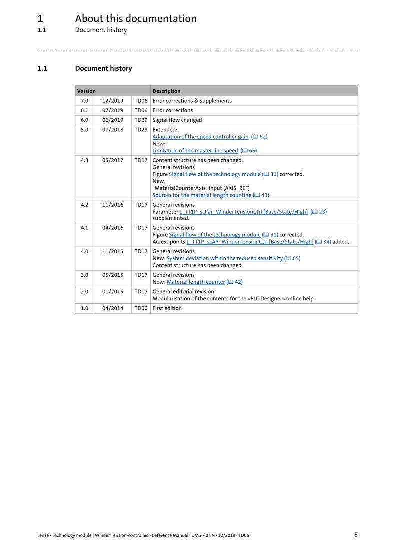
1.1 Document history
Version Description
7.0 12/2019 TD06 Error corrections & supplements
6.1 07/2019 TD06 Error corrections
6.0 06/2019 TD29 Signal flow changed
5.0 07/2018 TD29 Extended:Adaptation of the speed controller gain ( 62)New:Limitation of the master line speed ( 66)
4.3 05/2017 TD17 Content structure has been changed.General revisionsFigure Signal flow of the technology module ( 31) corrected.New:"MaterialCounterAxis" input (AXIS_REF)Sources for the material length counting ( 43)
4.2 11/2016 TD17 General revisionsParameter L_TT1P_scPar_WinderTensionCtrl [Base/State/High] ( 23) supplemented.
4.1 04/2016 TD17 General revisionsFigure Signal flow of the technology module ( 31) corrected.Access points L_TT1P_scAP_WinderTensionCtrl [Base/State/High] ( 34) added.
4.0 11/2015 TD17 General revisionsNew: System deviation within the reduced sensitivity ( 65)Content structure has been changed.
3.0 05/2015 TD17 General revisionsNew: Material length counter ( 42)
2.0 01/2015 TD17 General editorial revisionModularisation of the contents for the »PLC Designer« online help
1.0 04/2014 TD00 First edition

1 About this documentation1.2 Conventions used
6 Lenze · Technology module | Winder Tension-controlled · Reference Manual · DMS 7.0 EN · 12/2019 · TD06
_ _ _ _ _ _ _ _ _ _ _ _ _ _ _ _ _ _ _ _ _ _ _ _ _ _ _ _ _ _ _ _ _ _ _ _ _ _ _ _ _ _ _ _ _ _ _ _ _ _ _ _ _ _ _ _ _ _ _ _ _ _ _ _
1.2 Conventions used
This documentation uses the following conventions to distinguish between different types ofinformation:
Variable names
The conventions used by Lenze for the variable names of Lenze system blocks, function blocks, andfunctions are based on the "Hungarian Notation". This notation makes it possible to identify themost important properties (e.g. the data type) of the corresponding variable by means of its name,e.g. xAxisEnabled.
Type of information Highlighting Examples/notes
Spelling of numbers
Decimal separator Point The decimal point is always used.For example: 1234.56
Text
Program name » « »PLC Designer« ...
Variable names italics By setting bEnable to TRUE...
Function blocks bold The L_MC1P_AxisBasicControl function block ...
Function libraries The L_TT1P_TechnologyModules function library ...
Source code Font"Courier new"
...dwNumerator := 1;dwDenominator := 1;...
Icons
Page reference ( 6) Reference to further information: Page number in PDF file.
Lenze · Technology module | Winder Tension-controlled · Reference Manual · DMS 7.0 EN · 12/2019 · TD06 7
1 About this documentation1.3 Definition of the notes used
_ _ _ _ _ _ _ _ _ _ _ _ _ _ _ _ _ _ _ _ _ _ _ _ _ _ _ _ _ _ _ _ _ _ _ _ _ _ _ _ _ _ _ _ _ _ _ _ _ _ _ _ _ _ _ _ _ _ _ _ _ _ _ _
1.3 Definition of the notes used
The following signal words and symbols are used in this documentation to indicate dangers andimportant information:
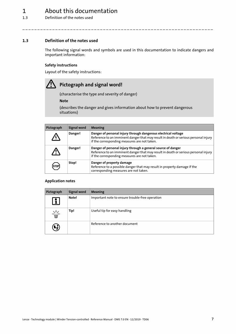
Safety instructions
Layout of the safety instructions:
Application notes
Pictograph and signal word!
(characterise the type and severity of danger)
Note
(describes the danger and gives information about how to prevent dangerous situations)
Pictograph Signal word Meaning
Danger! Danger of personal injury through dangerous electrical voltageReference to an imminent danger that may result in death or serious personal injury if the corresponding measures are not taken.
Danger! Danger of personal injury through a general source of dangerReference to an imminent danger that may result in death or serious personal injury if the corresponding measures are not taken.
Stop! Danger of property damageReference to a possible danger that may result in property damage if the corresponding measures are not taken.
Pictograph Signal word Meaning
Note! Important note to ensure trouble-free operation
Tip! Useful tip for easy handling
Reference to another document
2 Safety instructions
8 Lenze · Technology module | Winder Tension-controlled · Reference Manual · DMS 7.0 EN · 12/2019 · TD06
_ _ _ _ _ _ _ _ _ _ _ _ _ _ _ _ _ _ _ _ _ _ _ _ _ _ _ _ _ _ _ _ _ _ _ _ _ _ _ _ _ _ _ _ _ _ _ _ _ _ _ _ _ _ _ _ _ _ _ _ _ _ _ _
2 Safety instructions
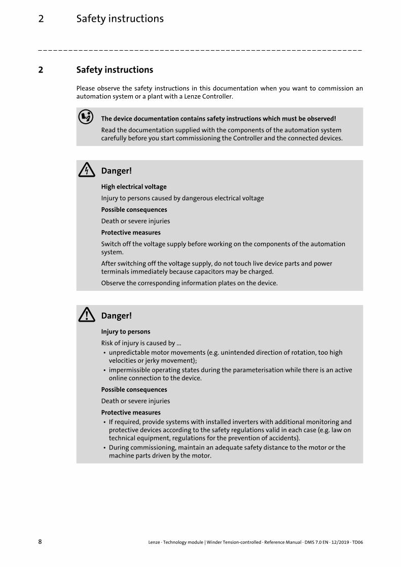
Please observe the safety instructions in this documentation when you want to commission anautomation system or a plant with a Lenze Controller.
The device documentation contains safety instructions which must be observed!
Read the documentation supplied with the components of the automation system carefully before you start commissioning the Controller and the connected devices.
Danger!
High electrical voltage
Injury to persons caused by dangerous electrical voltage
Possible consequences
Death or severe injuries
Protective measures
Switch off the voltage supply before working on the components of the automation system.
After switching off the voltage supply, do not touch live device parts and power terminals immediately because capacitors may be charged.
Observe the corresponding information plates on the device.
Danger!
Injury to persons
Risk of injury is caused by ...• unpredictable motor movements (e.g. unintended direction of rotation, too high
velocities or jerky movement);• impermissible operating states during the parameterisation while there is an active
online connection to the device.
Possible consequences
Death or severe injuries
Protective measures• If required, provide systems with installed inverters with additional monitoring and
protective devices according to the safety regulations valid in each case (e.g. law on technical equipment, regulations for the prevention of accidents).
• During commissioning, maintain an adequate safety distance to the motor or the machine parts driven by the motor.

Lenze · Technology module | Winder Tension-controlled · Reference Manual · DMS 7.0 EN · 12/2019 · TD06 9
2 Safety instructions
_ _ _ _ _ _ _ _ _ _ _ _ _ _ _ _ _ _ _ _ _ _ _ _ _ _ _ _ _ _ _ _ _ _ _ _ _ _ _ _ _ _ _ _ _ _ _ _ _ _ _ _ _ _ _ _ _ _ _ _ _ _ _ _
Stop!
Damage or destruction of machine parts
Damage or destruction of machine parts can be caused by ...• Short circuit or static discharges (ESD);• unpredictable motor movements (e.g. unintended direction of rotation, too high
velocities or jerky movement);• impermissible operating states during the parameterisation while there is an active
online connection to the device.
Protective measures• Always switch off the voltage supply before working on the components of the
automation system.• Do not touch electronic components and contacts unless ESD measures were taken
beforehand.• If required, provide systems with installed inverters with additional monitoring and
protective devices according to the safety regulations valid in each case (e.g. law on technical equipment, regulations for the prevention of accidents).
3 Functional description for "Winder Tension-controlled"
10 Lenze · Technology module | Winder Tension-controlled · Reference Manual · DMS 7.0 EN · 12/2019 · TD06
_ _ _ _ _ _ _ _ _ _ _ _ _ _ _ _ _ _ _ _ _ _ _ _ _ _ _ _ _ _ _ _ _ _ _ _ _ _ _ _ _ _ _ _ _ _ _ _ _ _ _ _ _ _ _ _ _ _ _ _ _ _ _ _
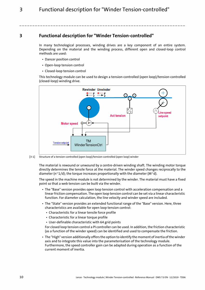
3 Functional description for "Winder Tension-controlled"
In many technological processes, winding drives are a key component of an entire system.Depending on the material and the winding process, different open and closed-loop controlmethods are used:
• Dancer position control
• Open-loop tension control
• Closed-loop tension control
This technology module can be used to design a tension-controlled (open loop)/tension-controlled(closed-loop) winding drive.
[3-1] Structure of a tension-controlled (open loop)/tension-controlled (open loop) winder
The material is rewound or unwound by a centre-driven winding shaft. The winding motor torquedirectly determines the tensile force at the material. The winder speed changes reciprocally to thediameter (n~1/d); the torque increases proportionally with the diameter (M~d).
The speed in the machine module is not determined by the winder. The material must have a fixedpoint so that a web tension can be built via the winder.
• The "Base" version provides open loop tension control with acceleration compensation and a linear friction compensation. The open loop tension control can be set via a linear characteristic function. For diameter calculation, the line velocity and winder speed are included.
• The "State" version provides an extended functional range of the "Base" version. Here, three characteristics are available for open loop tension control:• Characteristic for a linear tensile force profile• Characteristic for a linear torque profile• User-definable characteristic with 64 grid points
For closed loop tension control a PI controller can be used. In addition, the friction characteristic (as a function of the winder speed) can be identified and used to compensate the friction.
• The "High" version additionally offers the option to identify the moment of inertia of the winder axis and to integrate this value into the parameterisation of the technology module. Furthermore, the speed controller gain can be adapted during operation as a function of the current moment of inertia.
Lenze · Technology module | Winder Tension-controlled · Reference Manual · DMS 7.0 EN · 12/2019 · TD06 11
3 Functional description for "Winder Tension-controlled"
_ _ _ _ _ _ _ _ _ _ _ _ _ _ _ _ _ _ _ _ _ _ _ _ _ _ _ _ _ _ _ _ _ _ _ _ _ _ _ _ _ _ _ _ _ _ _ _ _ _ _ _ _ _ _ _ _ _ _ _ _ _ _ _
closed-loop speed control
A higher-level speed control only takes effect in the event of a web break to limit the speed of thedrive. In order to avoid that the setpoint torque is influenced by the speed limitation during normaloperation, a speed offset must be added to the speed setpoint calculated from the current linespeed and the current diameter.
The torque setpoint is composed of the tensile force setpoint multiplied by the current radius, thecorrecting signal for compensating the mechanical friction, and the correcting signal forcompensating the acceleration torque.
Closed-loop tension control
In order to achieve a good winding result, the friction and acceleration compensation must notsubstantially exceed the lowest load torque. If too great deviations with regard to the tensile forcein spite of friction and acceleration compensation are to be expected or are identified, the tensileforce setpoint can be corrected correspondingly by recording and closed-loop control of the tensileforce.

3 Functional description for "Winder Tension-controlled"3.1 Overview of the functions
12 Lenze · Technology module | Winder Tension-controlled · Reference Manual · DMS 7.0 EN · 12/2019 · TD06
_ _ _ _ _ _ _ _ _ _ _ _ _ _ _ _ _ _ _ _ _ _ _ _ _ _ _ _ _ _ _ _ _ _ _ _ _ _ _ _ _ _ _ _ _ _ _ _ _ _ _ _ _ _ _ _ _ _ _ _ _ _ _ _
3.1 Overview of the functions
In addition to the basic functions for operating the L_MC1P_AxisBasicControl function block, theStop function and the Holding function, the technology module offers the following functionalitiesthat are assigned to the "Base", "State", and "High" versions:
Functionality Variant
Base State High
Defining the winding direction (winding/unwinding) ( 36)
Automatic detection of the winding direction ( 36)
Defining the material feed to the winder ( 37)
Master value source for diameter calculation ( 38)
Speed feedforward control ( 38)
Calculation of the diameter ( 39)
Holding the diameter ( 40)
Defining the diameter / signal from the diameter sensor ( 41)
Material length counter ( 42)
Sources for the material length counting ( 43)
Manual jog (jogging) ( 45)
Synchronisation to the line velocity ( 46)
Trimming ( 47)
Tension control via characteristic function (Base version) ( 48)
Acceleration compensation ( 51)
Web break monitoring ( 53)
Persistent variables ( 54)
Limitation of the master line speed ( 66)
Tension control via characteristic function/winding characteristic ( 51)
Friction identification and compensation ( 56)
PI controller for tension control ( 59)
Identification of the moments of inertia ( 60)
Adaptation of the speed controller gain ( 62)
System deviation within the reduced sensitivity
»PLC Designer« Online help
Here you will find detailed information on the L_MC1P_AxisBasicControl function block, the stop function and the holding function.
Lenze · Technology module | Winder Tension-controlled · Reference Manual · DMS 7.0 EN · 12/2019 · TD06 13
3 Functional description for "Winder Tension-controlled"3.2 Important notes on how to operate the technology module
_ _ _ _ _ _ _ _ _ _ _ _ _ _ _ _ _ _ _ _ _ _ _ _ _ _ _ _ _ _ _ _ _ _ _ _ _ _ _ _ _ _ _ _ _ _ _ _ _ _ _ _ _ _ _ _ _ _ _ _ _ _ _ _
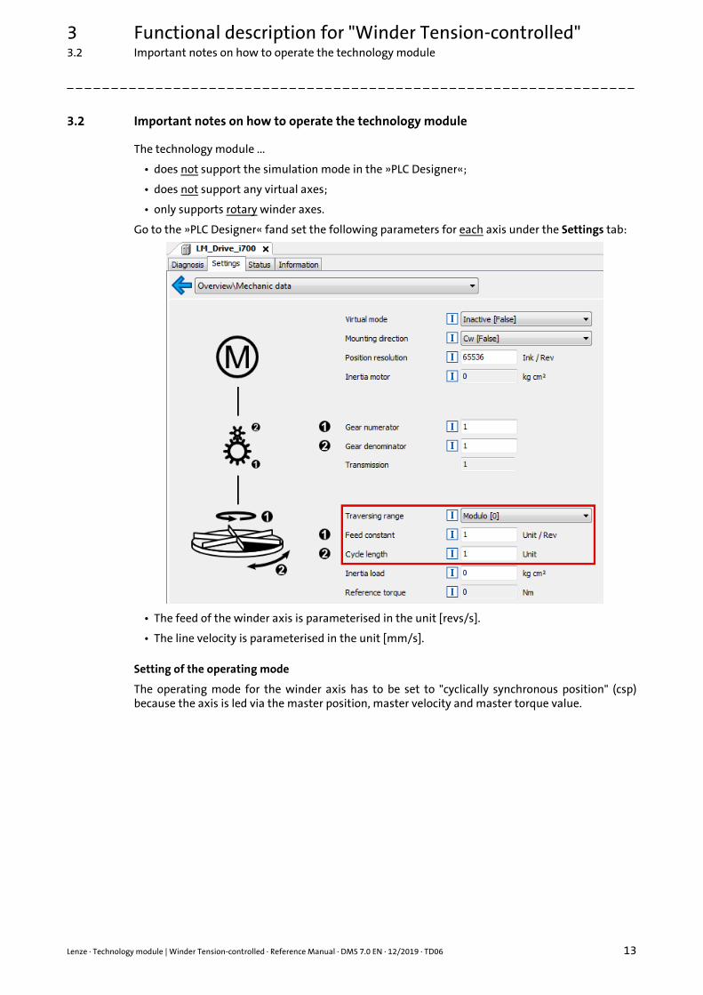
3.2 Important notes on how to operate the technology module
The technology module ...
• does not support the simulation mode in the »PLC Designer«;
• does not support any virtual axes;
• only supports rotary winder axes.
Go to the »PLC Designer« fand set the following parameters for each axis under the Settings tab:
• The feed of the winder axis is parameterised in the unit [revs/s].
• The line velocity is parameterised in the unit [mm/s].
Setting of the operating mode
The operating mode for the winder axis has to be set to "cyclically synchronous position" (csp)because the axis is led via the master position, master velocity and master torque value.
3 Functional description for "Winder Tension-controlled"3.2 Important notes on how to operate the technology module
14 Lenze · Technology module | Winder Tension-controlled · Reference Manual · DMS 7.0 EN · 12/2019 · TD06
_ _ _ _ _ _ _ _ _ _ _ _ _ _ _ _ _ _ _ _ _ _ _ _ _ _ _ _ _ _ _ _ _ _ _ _ _ _ _ _ _ _ _ _ _ _ _ _ _ _ _ _ _ _ _ _ _ _ _ _ _ _ _ _
Controlled start of the axes
Motion commands that are set in the inhibited axis state (xAxisEnabled = FALSE) after enable(xRegulatorOn = TRUE) must be activated again by a FALSETRUE edge.
In this way it is prevented that the drive starts in an uncontrolled manner after controller enable.
Example Manual jog (jogging) ( 45):
1. In the inhibited axis state (xAxisEnabled = FALSE), xJogPos is set to TRUE.• xRegulatorOn = FALSE (axis is inhibited.)
==> "READY" state (xAxisEnabled = FALSE)• xJogPos = TRUE (manual jog is to be executed.)
2. Enable axis.• xRegulatorOn = TRUE
==> "READY" state (xAxisEnabled = TRUE)
3. Execute manual jog.• xJogPos = FALSETRUE
==> "JOGPOS" state
Lenze · Technology module | Winder Tension-controlled · Reference Manual · DMS 7.0 EN · 12/2019 · TD06 15
3 Functional description for "Winder Tension-controlled"3.3 L_TT1P_WinderTensionCtrl[Base/State/High] function block
_ _ _ _ _ _ _ _ _ _ _ _ _ _ _ _ _ _ _ _ _ _ _ _ _ _ _ _ _ _ _ _ _ _ _ _ _ _ _ _ _ _ _ _ _ _ _ _ _ _ _ _ _ _ _ _ _ _ _ _ _ _ _ _
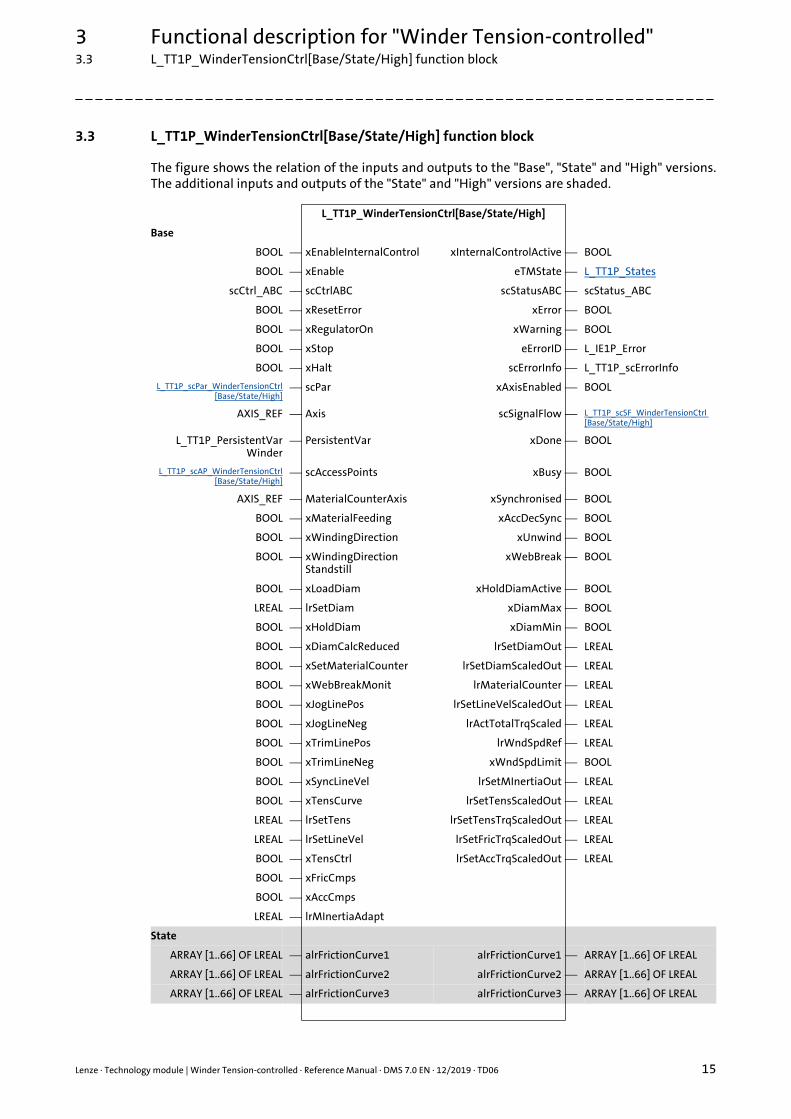
3.3 L_TT1P_WinderTensionCtrl[Base/State/High] function block
The figure shows the relation of the inputs and outputs to the "Base", "State" and "High" versions.The additional inputs and outputs of the "State" and "High" versions are shaded.
L_TT1P_WinderTensionCtrl[Base/State/High]
Base
BOOL ⎯ xEnableInternalControl xInternalControlActive ⎯ BOOL
BOOL ⎯ xEnable eTMState ⎯ L_TT1P_States
scCtrl_ABC ⎯ scCtrlABC scStatusABC ⎯ scStatus_ABC
BOOL ⎯ xResetError xError ⎯ BOOL
BOOL ⎯ xRegulatorOn xWarning ⎯ BOOL
BOOL ⎯ xStop eErrorID ⎯ L_IE1P_Error
BOOL ⎯ xHalt scErrorInfo ⎯ L_TT1P_scErrorInfo
L_TT1P_scPar_WinderTensionCtrl[Base/State/High]
⎯ scPar xAxisEnabled ⎯ BOOL
AXIS_REF ⎯ Axis scSignalFlow ⎯ L_TT1P_scSF_WinderTensionCtrl [Base/State/High]
L_TT1P_PersistentVarWinder
⎯ PersistentVar xDone ⎯ BOOL
L_TT1P_scAP_WinderTensionCtrl[Base/State/High]
⎯ scAccessPoints xBusy ⎯ BOOL
AXIS_REF ⎯ MaterialCounterAxis xSynchronised ⎯ BOOL
BOOL ⎯ xMaterialFeeding xAccDecSync ⎯ BOOL
BOOL ⎯ xWindingDirection xUnwind ⎯ BOOL
BOOL ⎯ xWindingDirectionStandstill
xWebBreak ⎯ BOOL
BOOL ⎯ xLoadDiam xHoldDiamActive ⎯ BOOL
LREAL ⎯ lrSetDiam xDiamMax ⎯ BOOL
BOOL ⎯ xHoldDiam xDiamMin ⎯ BOOL
BOOL ⎯ xDiamCalcReduced lrSetDiamOut ⎯ LREAL
BOOL ⎯ xSetMaterialCounter lrSetDiamScaledOut ⎯ LREAL
BOOL ⎯ xWebBreakMonit lrMaterialCounter ⎯ LREAL
BOOL ⎯ xJogLinePos lrSetLineVelScaledOut ⎯ LREAL
BOOL ⎯ xJogLineNeg lrActTotalTrqScaled ⎯ LREAL
BOOL ⎯ xTrimLinePos lrWndSpdRef ⎯ LREAL
BOOL ⎯ xTrimLineNeg xWndSpdLimit ⎯ BOOL
BOOL ⎯ xSyncLineVel lrSetMInertiaOut ⎯ LREAL
BOOL ⎯ xTensCurve lrSetTensScaledOut ⎯ LREAL
LREAL ⎯ lrSetTens lrSetTensTrqScaledOut ⎯ LREAL
LREAL ⎯ lrSetLineVel lrSetFricTrqScaledOut ⎯ LREAL
BOOL ⎯ xTensCtrl lrSetAccTrqScaledOut ⎯ LREAL
BOOL ⎯ xFricCmps
BOOL ⎯ xAccCmps
LREAL ⎯ lrMInertiaAdapt
State
ARRAY [1..66] OF LREAL ⎯ alrFrictionCurve1 alrFrictionCurve1 ⎯ ARRAY [1..66] OF LREAL
ARRAY [1..66] OF LREAL ⎯ alrFrictionCurve2 alrFrictionCurve2 ⎯ ARRAY [1..66] OF LREAL
ARRAY [1..66] OF LREAL ⎯ alrFrictionCurve3 alrFrictionCurve3 ⎯ ARRAY [1..66] OF LREAL
3 Functional description for "Winder Tension-controlled"3.3 L_TT1P_WinderTensionCtrl[Base/State/High] function block
16 Lenze · Technology module | Winder Tension-controlled · Reference Manual · DMS 7.0 EN · 12/2019 · TD06
_ _ _ _ _ _ _ _ _ _ _ _ _ _ _ _ _ _ _ _ _ _ _ _ _ _ _ _ _ _ _ _ _ _ _ _ _ _ _ _ _ _ _ _ _ _ _ _ _ _ _ _ _ _ _ _ _ _ _ _ _ _ _ _
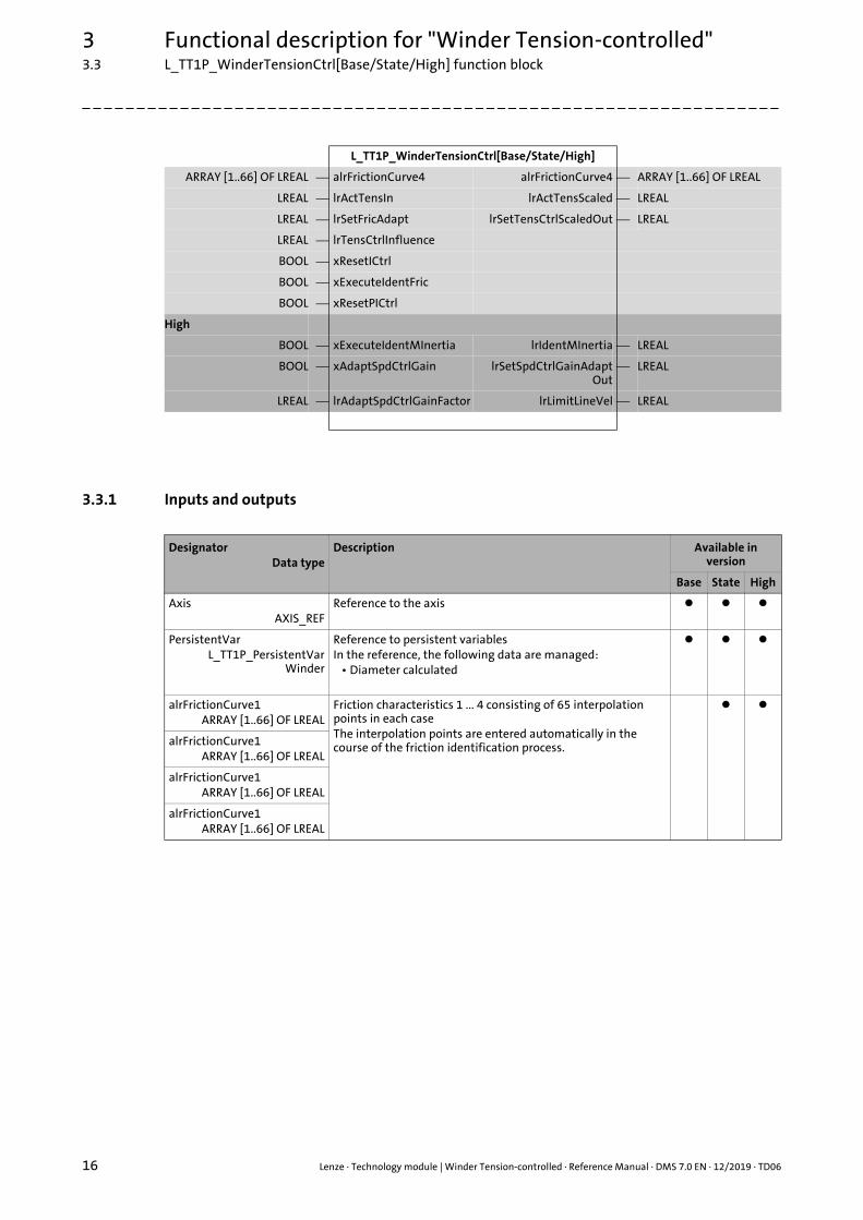
3.3.1 Inputs and outputs
ARRAY [1..66] OF LREAL ⎯ alrFrictionCurve4 alrFrictionCurve4 ⎯ ARRAY [1..66] OF LREAL
LREAL ⎯ lrActTensIn lrActTensScaled ⎯ LREAL
LREAL ⎯ lrSetFricAdapt lrSetTensCtrlScaledOut ⎯ LREAL
LREAL ⎯ lrTensCtrlInfluence
BOOL ⎯ xResetICtrl
BOOL ⎯ xExecuteIdentFric
BOOL ⎯ xResetPICtrl
High
BOOL ⎯ xExecuteIdentMInertia lrIdentMInertia ⎯ LREAL
BOOL ⎯ xAdaptSpdCtrlGain lrSetSpdCtrlGainAdaptOut
⎯ LREAL
LREAL ⎯ lrAdaptSpdCtrlGainFactor lrLimitLineVel ⎯ LREAL
L_TT1P_WinderTensionCtrl[Base/State/High]
DesignatorData type
Description Available in version
Base State High
AxisAXIS_REF
Reference to the axis
PersistentVarL_TT1P_PersistentVar
Winder
Reference to persistent variablesIn the reference, the following data are managed:
• Diameter calculated
alrFrictionCurve1ARRAY [1..66] OF LREAL
Friction characteristics 1 ... 4 consisting of 65 interpolation points in each caseThe interpolation points are entered automatically in the course of the friction identification process.
alrFrictionCurve1ARRAY [1..66] OF LREAL
alrFrictionCurve1ARRAY [1..66] OF LREAL
alrFrictionCurve1ARRAY [1..66] OF LREAL
Lenze · Technology module | Winder Tension-controlled · Reference Manual · DMS 7.0 EN · 12/2019 · TD06 17
3 Functional description for "Winder Tension-controlled"3.3 L_TT1P_WinderTensionCtrl[Base/State/High] function block
_ _ _ _ _ _ _ _ _ _ _ _ _ _ _ _ _ _ _ _ _ _ _ _ _ _ _ _ _ _ _ _ _ _ _ _ _ _ _ _ _ _ _ _ _ _ _ _ _ _ _ _ _ _ _ _ _ _ _ _ _ _ _ _
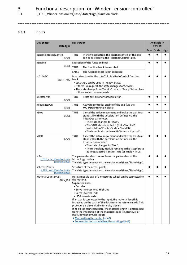
3.3.2 inputs
DesignatorData type
Description Available in version
Base State High
xEnableInternalControlBOOL
TRUE In the visualisation, the internal control of the axis can be selected via the "Internal Control" axis.
xEnableBOOL
Execution of the function block
TRUE The function block is executed.
FALSE The function block is not executed.
scCtrlABCscCtrl_ABC
Input structure for the L_MC1P_AxisBasicControl function block
• scCtrlABC can be used in "Ready" state.• If there is a request, the state changes to "Service".• The state change from "Service" back to "Ready" takes place
if there are no more requests.
xResetErrorBOOL
TRUE Reset axis error or software error.
xRegulatorOnBOOL
TRUE Activate controller enable of the axis (via the MC_Power function block).
xStopBOOL
TRUE Cancel the active movement and brake the axis to a standstill with the deceleration defined via the lrStopDec parameter.
• The state changes to "Stop".• The STOP state is exited if (Not xStop AND
Not xHalt) AND eAxisState = StandStill• The input is also active with "Internal Control".
xHaltBOOL
TRUE Cancel the active movement and brake the axis to a standstill with the deceleration defined via the IrHaltDec parameter.
• The state changes to "Stop".• The technology module remains in the "Stop" state
as long as xStop is set to TRUE (or xHalt = TRUE).
scParL_TT1P_scPar_WinderTensionCtrl
[Base/State/High]
The parameter structure contains the parameters of the technology module.The data type depends on the version used (Base/State/High).
scAccessPointsL_TT1P_scAP_WinderTensionCtrl
[Base/State/High]
Structure of the access pointsThe data type depends on the version used (Base/State/High).
MaterialCounterAxisAXIS_REF
Here a modulo axis of a measuring wheel can be connected to the material.Supported axes:
• Encoder• Servo inverter 9400 HighLine• Servo inverter i700• i950 servo inverter
If an axis is connected to the input, the material length is increased on the basis of the data from the reference axis. This procedure is also suitable for noisy signals.If no axis is connected here, the material length is determined from the integration of the material speed (lrSetLineVel or lrSetLineVelDiamCalc input).Material length counter ( 42) Sources for the material length counting ( 43)

3 Functional description for "Winder Tension-controlled"3.3 L_TT1P_WinderTensionCtrl[Base/State/High] function block
18 Lenze · Technology module | Winder Tension-controlled · Reference Manual · DMS 7.0 EN · 12/2019 · TD06
_ _ _ _ _ _ _ _ _ _ _ _ _ _ _ _ _ _ _ _ _ _ _ _ _ _ _ _ _ _ _ _ _ _ _ _ _ _ _ _ _ _ _ _ _ _ _ _ _ _ _ _ _ _ _ _ _ _ _ _ _ _ _ _
xMaterialFeedingBOOL
Material feeding at the reels from the top or from the bottom• Initial value: FALSE
The following note applies to • L_TT1P_WinderDancerCtrl• L_TT1P_WinderTensionCtrl• L_TW2P_WinderDancerCtrl• L_TW2P_WinderDancerCtrl
Changes in the setting at the input become effective immediately even during a movement. A changed input during operation may cause a speed jump of the winder axis.
TRUE Material feeding from the top
FALSE Material feeding from the bottom
xWindingDirectionBOOL
Winder function at positive line velocity (lrSetLineVel input > 0)• Initial value: FALSE
The following note applies to • L_TT1P_WinderDancerCtrl• L_TT1P_WinderTensionCtrl• L_TW2P_WinderDancerCtrl• L_TW2P_WinderDancerCtrl
Changes in the setting at the input become effective immediately even while moving. A changed input during operation may cause a speed jump of the winder axis.
TRUE Unwinder
FALSE Rewinder
xWindingDirectionStandstillBOOL
Function of the winder with idle line speed(lrSetLineVel input = 0)
• Initial value: FALSE
TRUE Unwinder
FALSE Rewinder
xLoadDiamBOOL
TRUE Load the (start) diameter [mm] from the lrSetDiam input.
• Initial value: FALSE
lrSetDiamLREAL
Defining a (start) diameterThe diameter is loaded cyclically when the xLoadDiam is set to TRUE.
• Unit: mm• Initial value: 0
xHoldDiamBOOL
Hold/Do not hold current diameter• Initial value: FALSE
TRUE Current diameter is held.
FALSE The current diameter is not held.
xDiamCalcReducedBOOL
Change-over of the diameter calculation mode between long/short distance
• Initial value: FALSE
TRUE Diameter is updated after the short distance.
FALSE Diameter is updated after the long distance.
xSetMaterialCounterBOOL
The input is edge-controlled and evaluates the FALSETRUE edge.
• Initial value: FALSE
TRUE Sets the material length counter (lrMaterialCounter output) to the value set under the lrSetMaterialPos parameter.
DesignatorData type
Description Available in version
Base State High
Lenze · Technology module | Winder Tension-controlled · Reference Manual · DMS 7.0 EN · 12/2019 · TD06 19
3 Functional description for "Winder Tension-controlled"3.3 L_TT1P_WinderTensionCtrl[Base/State/High] function block
_ _ _ _ _ _ _ _ _ _ _ _ _ _ _ _ _ _ _ _ _ _ _ _ _ _ _ _ _ _ _ _ _ _ _ _ _ _ _ _ _ _ _ _ _ _ _ _ _ _ _ _ _ _ _ _ _ _ _ _ _ _ _ _
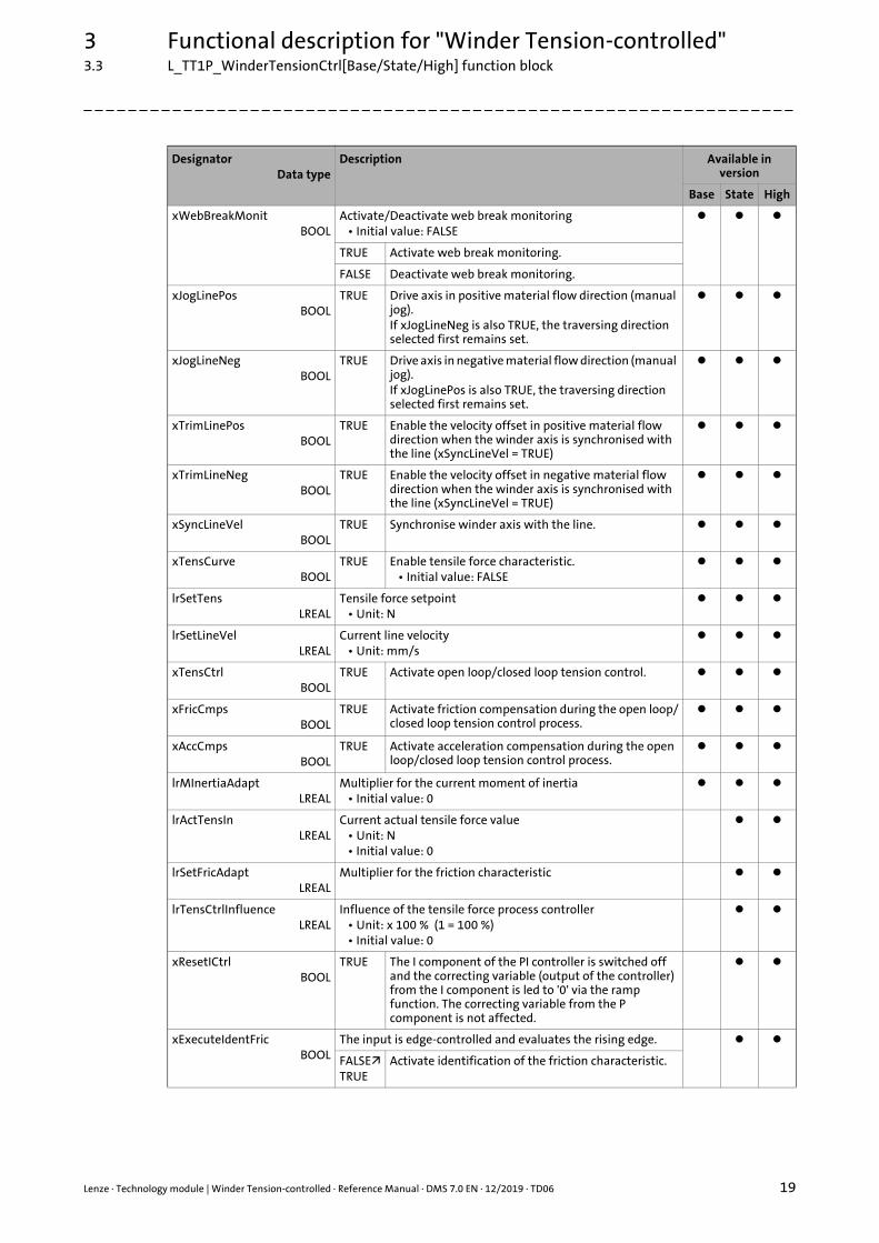
xWebBreakMonitBOOL
Activate/Deactivate web break monitoring• Initial value: FALSE
TRUE Activate web break monitoring.
FALSE Deactivate web break monitoring.
xJogLinePosBOOL
TRUE Drive axis in positive material flow direction (manual jog).If xJogLineNeg is also TRUE, the traversing direction selected first remains set.
xJogLineNegBOOL
TRUE Drive axis in negative material flow direction (manual jog).If xJogLinePos is also TRUE, the traversing direction selected first remains set.
xTrimLinePosBOOL
TRUE Enable the velocity offset in positive material flow direction when the winder axis is synchronised with the line (xSyncLineVel = TRUE)
xTrimLineNegBOOL
TRUE Enable the velocity offset in negative material flow direction when the winder axis is synchronised with the line (xSyncLineVel = TRUE)
xSyncLineVelBOOL
TRUE Synchronise winder axis with the line.
xTensCurveBOOL
TRUE Enable tensile force characteristic.• Initial value: FALSE
lrSetTensLREAL
Tensile force setpoint• Unit: N
lrSetLineVelLREAL
Current line velocity• Unit: mm/s
xTensCtrlBOOL
TRUE Activate open loop/closed loop tension control.
xFricCmpsBOOL
TRUE Activate friction compensation during the open loop/closed loop tension control process.
xAccCmpsBOOL
TRUE Activate acceleration compensation during the open loop/closed loop tension control process.
lrMInertiaAdaptLREAL
Multiplier for the current moment of inertia• Initial value: 0
lrActTensInLREAL
Current actual tensile force value• Unit: N• Initial value: 0
lrSetFricAdapt LREAL
Multiplier for the friction characteristic
lrTensCtrlInfluenceLREAL
Influence of the tensile force process controller• Unit: x 100 % (1 = 100 %)• Initial value: 0
xResetICtrlBOOL
TRUE The I component of the PI controller is switched off and the correcting variable (output of the controller) from the I component is led to '0' via the ramp function. The correcting variable from the P component is not affected.
xExecuteIdentFricBOOL
The input is edge-controlled and evaluates the rising edge.
FALSETRUE
Activate identification of the friction characteristic.
DesignatorData type
Description Available in version
Base State High
3 Functional description for "Winder Tension-controlled"3.3 L_TT1P_WinderTensionCtrl[Base/State/High] function block
20 Lenze · Technology module | Winder Tension-controlled · Reference Manual · DMS 7.0 EN · 12/2019 · TD06
_ _ _ _ _ _ _ _ _ _ _ _ _ _ _ _ _ _ _ _ _ _ _ _ _ _ _ _ _ _ _ _ _ _ _ _ _ _ _ _ _ _ _ _ _ _ _ _ _ _ _ _ _ _ _ _ _ _ _ _ _ _ _ _
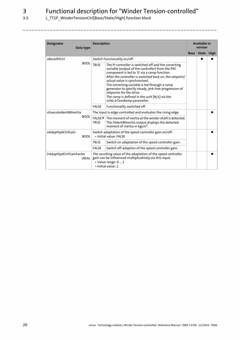
xResetPICtrl BOOL
Switch functionality on/off
TRUE The PI controller is switched off and the correcting variable (output of the controller) from the PID component is led to '0' via a ramp function.After the controller is switched back on, the setpoint/actual value is synchronised. The correcting variable is led through a ramp generator to specify steady, jerk-free progression of setpoints for the drive. The ramp is defined in the unit [N/s] via the scPar.lrTensRamp parameter.
FALSE Functionality switched off
xExecuteIdentMInertiaBOOL
The input is edge-controlled and evaluates the rising edge.
FALSETRUE
The moment of inertia at the winder shaft is detected.The lrIdentMInertia output displays the detected moment of inertia in kgcm2.
xAdaptSpdCtrlGainBOOL
Switch adaptation of the speed controller gain on/off.• Initial value: FALSE
TRUE Switch on adaptation of the speed controller gain.
FALSE Switch off adaption of the speed controller gain.
lrAdaptSpdCtrlGainFactorLREAL
The resulting value of the adaptation of the speed controller gain can be influenced multiplicatively via this input.
• Value range: 0 ... 1• Initial value: 1
DesignatorData type
Description Available in version
Base State High

Lenze · Technology module | Winder Tension-controlled · Reference Manual · DMS 7.0 EN · 12/2019 · TD06 21
3 Functional description for "Winder Tension-controlled"3.3 L_TT1P_WinderTensionCtrl[Base/State/High] function block
_ _ _ _ _ _ _ _ _ _ _ _ _ _ _ _ _ _ _ _ _ _ _ _ _ _ _ _ _ _ _ _ _ _ _ _ _ _ _ _ _ _ _ _ _ _ _ _ _ _ _ _ _ _ _ _ _ _ _ _ _ _ _ _
3.3.3 outputs
DesignatorData type
Description Available in version
Base State High
xInternalControlActiveBOOL
The internal control of the axis is activated via the visualisation. (xEnableInternalControl input = TRUE)
eTMStateL_TT1P_States
Current state of the technology moduleState machine ( 28)
scStatusABCscStatus_ABC
Structure of the status data of the L_MC1P_AxisBasicControl function block
xErrorBOOL
TRUE There is an error in the technology module.
xWarningBOOL
TRUE There is a warning in the technology module.
eErrorIDL_IE1P_Error
ID of the error or warning message if xError = TRUE or xWarning = TRUE.
"FAST technology modules" reference manual:Here you can find information on error or warning messages.
scErrorInfoL_TT1P_scErrorInfo
Error information structure for a more detailed analysis of the error cause
xAxisEnabledBOOL
TRUE The axis is enabled.
scSignalFlowL_TT1P_scSF_WinderTensionCtrl
[Base/State/High]
Structure of the signal flowThe data type depends on the version used (Base/State/High).Signal flow diagrams ( 30)
xDoneBOOL
TRUE The request/action has been completed successfully.
xBusyBOOL
TRUE The request/action is currently being executed.
xSynchronisedBOOL
TRUE The winder is synchronised with the line speed.
xAccDecSyncBOOL
TRUE The synchronisation function is active.Synchronisation of the winder is carried out or cancelled.
xUnwindBOOL
Status bit for unwinder and rewinder
TRUE Unwinder
FALSE Rewinder
xWebBreakBOOL
TRUE A web break has occurred.
xHoldDiamActiveBOOL
TRUE Current diameter is held.
xDiamMaxBOOL
TRUE The maximum diameter has been reached.
xDiamMinBOOL
TRUE The minimum diameter has been reached.
lrSetDiamOutLREAL
Current diameter calculated• Unit: mm
lrSetDiamScaledOutLREAL
Current diameter calculated and scaled• Unit: x 100 %• 1 = 100 % = parameter lrMaxDiam
3 Functional description for "Winder Tension-controlled"3.3 L_TT1P_WinderTensionCtrl[Base/State/High] function block
22 Lenze · Technology module | Winder Tension-controlled · Reference Manual · DMS 7.0 EN · 12/2019 · TD06
_ _ _ _ _ _ _ _ _ _ _ _ _ _ _ _ _ _ _ _ _ _ _ _ _ _ _ _ _ _ _ _ _ _ _ _ _ _ _ _ _ _ _ _ _ _ _ _ _ _ _ _ _ _ _ _ _ _ _ _ _ _ _ _
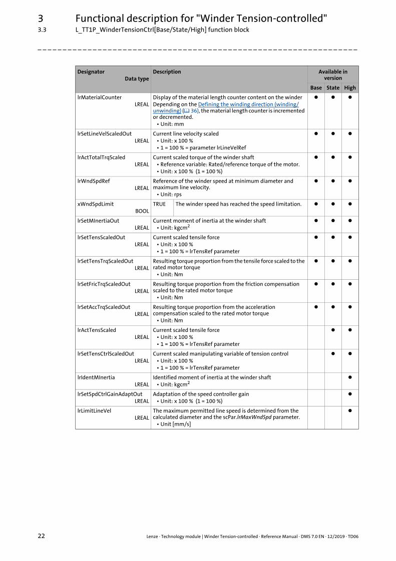
lrMaterialCounterLREAL
Display of the material length counter content on the winderDepending on the Defining the winding direction (winding/unwinding) ( 36), the material length counter is incremented or decremented.
• Unit: mm
lrSetLineVelScaledOutLREAL
Current line velocity scaled• Unit: x 100 %• 1 = 100 % = parameter lrLineVelRef
lrActTotalTrqScaledLREAL
Current scaled torque of the winder shaft• Reference variable: Rated/reference torque of the motor.• Unit: x 100 % (1 = 100 %)
lrWndSpdRefLREAL
Reference of the winder speed at minimum diameter and maximum line velocity.
• Unit: rps
xWndSpdLimitBOOL
TRUE The winder speed has reached the speed limitation.
lrSetMInertiaOutLREAL
Current moment of inertia at the winder shaft• Unit: kgcm2
lrSetTensScaledOutLREAL
Current scaled tensile force• Unit: x 100 %• 1 = 100 % = lrTensRef parameter
lrSetTensTrqScaledOutLREAL
Resulting torque proportion from the tensile force scaled to the rated motor torque
• Unit: Nm
lrSetFricTrqScaledOutLREAL
Resulting torque proportion from the friction compensation scaled to the rated motor torque
• Unit: Nm
lrSetAccTrqScaledOutLREAL
Resulting torque proportion from the acceleration compensation scaled to the rated motor torque
• Unit: Nm
lrActTensScaledLREAL
Current scaled tensile force• Unit: x 100 %• 1 = 100 % = lrTensRef parameter
lrSetTensCtrlScaledOutLREAL
Current scaled manipulating variable of tension control• Unit: x 100 %• 1 = 100 % = lrTensRef parameter
lrIdentMInertiaLREAL
Identified moment of inertia at the winder shaft• Unit: kgcm2
lrSetSpdCtrlGainAdaptOutLREAL
Adaptation of the speed controller gain• Unit: x 100 % (1 = 100 %)
lrLimitLineVelLREAL
The maximum permitted line speed is determined from the calculated diameter and the scPar.lrMaxWndSpd parameter.
• Unit [mm/s]
DesignatorData type
Description Available in version
Base State High
Lenze · Technology module | Winder Tension-controlled · Reference Manual · DMS 7.0 EN · 12/2019 · TD06 23
3 Functional description for "Winder Tension-controlled"3.3 L_TT1P_WinderTensionCtrl[Base/State/High] function block
_ _ _ _ _ _ _ _ _ _ _ _ _ _ _ _ _ _ _ _ _ _ _ _ _ _ _ _ _ _ _ _ _ _ _ _ _ _ _ _ _ _ _ _ _ _ _ _ _ _ _ _ _ _ _ _ _ _ _ _ _ _ _ _
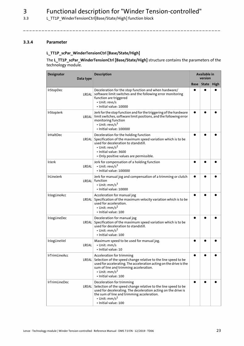
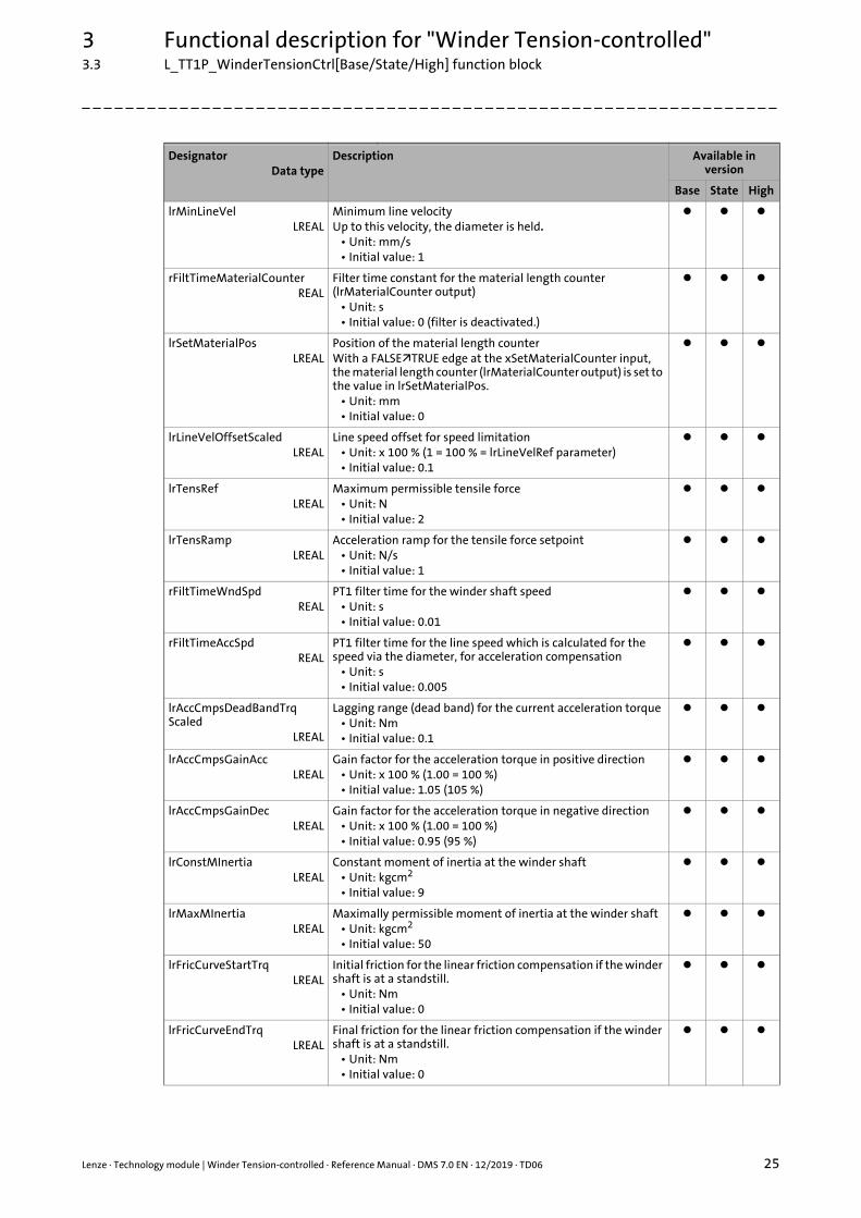
3.3.4 Parameter
L_TT1P_scPar_WinderTensionCtrl [Base/State/High]
The L_TT1P_scPar_WinderTensionCtrl [Base/State/High] structure contains the parameters of thetechnology module.
DesignatorData type
Description Available in version
Base State High
lrStopDecLREAL
Deceleration for the stop function and when hardware/software limit switches and the following error monitoring function are triggered
• Unit: revs/s• Initial value: 10000
lrStopJerkLREAL
Jerk for the stop function and for the triggering of the hardware limit switches, software limit positions, and the following error monitoring function
• Unit: revs/s3
• Initial value: 100000
lrHaltDecLREAL
Deceleration for the holding functionSpecification of the maximum speed variation which is to be used for deceleration to standstill.
• Unit: revs/s2
• Initial value: 3600• Only positive values are permissible.
lrJerkLREAL
Jerk for compensation of a holding function• Unit: revs/s3
• Initial value: 100000
lrLineJerkLREAL
Jerk for manual jog and compensation of a trimming or clutch function
• Unit: mm/s3
• Initial value: 10000
lrJogLineAccLREAL
Acceleration for manual jogSpecification of the maximum velocity variation which is to be used for acceleration.
• Unit: mm/s2
• Initial value: 100
lrJogLineDecLREAL
Deceleration for manual jogSpecification of the maximum speed variation which is to be used for deceleration to standstill.
• Unit: mm/s2
• Initial value: 100
lrJogLineVelLREAL
Maximum speed to be used for manual jog.• Unit: mm/s• Initial value: 10
lrTrimLineAccLREAL
Acceleration for trimmingSelection of the speed change relative to the line speed to be used for accelerating. The acceleration acting on the drive is the sum of line and trimming acceleration.
• Unit: mm/s2
• Initial value: 100
lrTrimLineDecLREAL
Deceleration for trimmingSelection of the speed change relative to the line speed to be used for decelerating. The deceleration acting on the drive is the sum of line and trimming acceleration.
• Unit: mm/s2
• Initial value: 100
3 Functional description for "Winder Tension-controlled"3.3 L_TT1P_WinderTensionCtrl[Base/State/High] function block
24 Lenze · Technology module | Winder Tension-controlled · Reference Manual · DMS 7.0 EN · 12/2019 · TD06
_ _ _ _ _ _ _ _ _ _ _ _ _ _ _ _ _ _ _ _ _ _ _ _ _ _ _ _ _ _ _ _ _ _ _ _ _ _ _ _ _ _ _ _ _ _ _ _ _ _ _ _ _ _ _ _ _ _ _ _ _ _ _ _
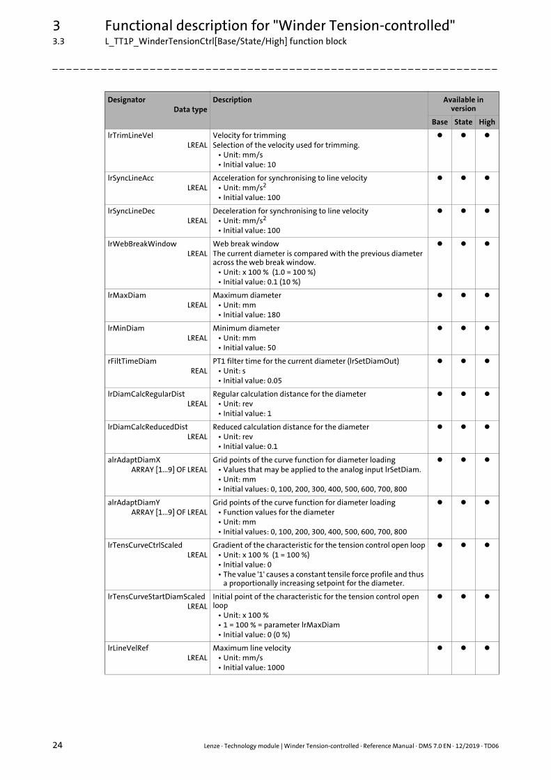
lrTrimLineVelLREAL
Velocity for trimmingSelection of the velocity used for trimming.
• Unit: mm/s• Initial value: 10
lrSyncLineAccLREAL
Acceleration for synchronising to line velocity• Unit: mm/s2
• Initial value: 100
lrSyncLineDecLREAL
Deceleration for synchronising to line velocity• Unit: mm/s2
• Initial value: 100
lrWebBreakWindowLREAL
Web break windowThe current diameter is compared with the previous diameter across the web break window.
• Unit: x 100 % (1.0 = 100 %)• Initial value: 0.1 (10 %)
lrMaxDiamLREAL
Maximum diameter• Unit: mm• Initial value: 180
lrMinDiamLREAL
Minimum diameter• Unit: mm• Initial value: 50
rFiltTimeDiamREAL
PT1 filter time for the current diameter (lrSetDiamOut)• Unit: s• Initial value: 0.05
lrDiamCalcRegularDistLREAL
Regular calculation distance for the diameter• Unit: rev• Initial value: 1
lrDiamCalcReducedDistLREAL
Reduced calculation distance for the diameter• Unit: rev• Initial value: 0.1
alrAdaptDiamXARRAY [1...9] OF LREAL
Grid points of the curve function for diameter loading• Values that may be applied to the analog input lrSetDiam.• Unit: mm• Initial values: 0, 100, 200, 300, 400, 500, 600, 700, 800
alrAdaptDiamYARRAY [1...9] OF LREAL
Grid points of the curve function for diameter loading• Function values for the diameter• Unit: mm• Initial values: 0, 100, 200, 300, 400, 500, 600, 700, 800
lrTensCurveCtrlScaledLREAL
Gradient of the characteristic for the tension control open loop• Unit: x 100 % (1 = 100 %)• Initial value: 0• The value '1' causes a constant tensile force profile and thus
a proportionally increasing setpoint for the diameter.
lrTensCurveStartDiamScaledLREAL
Initial point of the characteristic for the tension control open loop
• Unit: x 100 %• 1 = 100 % = parameter lrMaxDiam• Initial value: 0 (0 %)
lrLineVelRefLREAL
Maximum line velocity• Unit: mm/s• Initial value: 1000
DesignatorData type
Description Available in version
Base State High
Lenze · Technology module | Winder Tension-controlled · Reference Manual · DMS 7.0 EN · 12/2019 · TD06 25
3 Functional description for "Winder Tension-controlled"3.3 L_TT1P_WinderTensionCtrl[Base/State/High] function block
_ _ _ _ _ _ _ _ _ _ _ _ _ _ _ _ _ _ _ _ _ _ _ _ _ _ _ _ _ _ _ _ _ _ _ _ _ _ _ _ _ _ _ _ _ _ _ _ _ _ _ _ _ _ _ _ _ _ _ _ _ _ _ _
lrMinLineVelLREAL
Minimum line velocityUp to this velocity, the diameter is held.
• Unit: mm/s• Initial value: 1
rFiltTimeMaterialCounterREAL
Filter time constant for the material length counter (lrMaterialCounter output)
• Unit: s• Initial value: 0 (filter is deactivated.)
lrSetMaterialPosLREAL
Position of the material length counterWith a FALSETRUE edge at the xSetMaterialCounter input, the material length counter (lrMaterialCounter output) is set to the value in lrSetMaterialPos.
• Unit: mm• Initial value: 0
lrLineVelOffsetScaledLREAL
Line speed offset for speed limitation• Unit: x 100 % (1 = 100 % = lrLineVelRef parameter)• Initial value: 0.1
lrTensRefLREAL
Maximum permissible tensile force• Unit: N• Initial value: 2
lrTensRampLREAL
Acceleration ramp for the tensile force setpoint• Unit: N/s• Initial value: 1
rFiltTimeWndSpdREAL
PT1 filter time for the winder shaft speed • Unit: s• Initial value: 0.01
rFiltTimeAccSpdREAL
PT1 filter time for the line speed which is calculated for the speed via the diameter, for acceleration compensation
• Unit: s• Initial value: 0.005
lrAccCmpsDeadBandTrqScaled
LREAL
Lagging range (dead band) for the current acceleration torque• Unit: Nm• Initial value: 0.1
lrAccCmpsGainAccLREAL
Gain factor for the acceleration torque in positive direction• Unit: x 100 % (1.00 = 100 %)• Initial value: 1.05 (105 %)
lrAccCmpsGainDecLREAL
Gain factor for the acceleration torque in negative direction• Unit: x 100 % (1.00 = 100 %)• Initial value: 0.95 (95 %)
lrConstMInertiaLREAL
Constant moment of inertia at the winder shaft• Unit: kgcm2
• Initial value: 9
lrMaxMInertiaLREAL
Maximally permissible moment of inertia at the winder shaft• Unit: kgcm2
• Initial value: 50
lrFricCurveStartTrqLREAL
Initial friction for the linear friction compensation if the winder shaft is at a standstill.
• Unit: Nm• Initial value: 0
lrFricCurveEndTrqLREAL
Final friction for the linear friction compensation if the winder shaft is at a standstill.
• Unit: Nm• Initial value: 0
DesignatorData type
Description Available in version
Base State High

3 Functional description for "Winder Tension-controlled"3.3 L_TT1P_WinderTensionCtrl[Base/State/High] function block
26 Lenze · Technology module | Winder Tension-controlled · Reference Manual · DMS 7.0 EN · 12/2019 · TD06
_ _ _ _ _ _ _ _ _ _ _ _ _ _ _ _ _ _ _ _ _ _ _ _ _ _ _ _ _ _ _ _ _ _ _ _ _ _ _ _ _ _ _ _ _ _ _ _ _ _ _ _ _ _ _ _ _ _ _ _ _ _ _ _
rFiltTimeFricSetSpdREAL
PT1 filter time for the winder shaft speed for friction compensation
• Unit: s• Initial value: 0.01
dwSelectTensCurveDWORD
Selection of the characteristic for tension control• Initial value: 0
0 Linear tensile force profile
1 Linear torque profile
2 Tensile force profile according to a specified characteristic
alrTensCurveARRAY [1...65] OF LREAL
Characteristic for tension control open loop consisting of 65 values.
lrTensCtrlGainLREAL
Controller gain• Initial value: 0
lrTensCtrlResetTimeLREAL
Controller reset time• Unit: s• Initial value: 0 (reset time deactivated)
lrIdentFricMaxSpdScaledLREAL
Speed for friction identification• Unit: x 100 % (1 = 100 % = max. speed at the lrWndSpdRef
output)• Initial value: 0.9
lrIdentFricAccDecLREAL
Acceleration for friction identification• Unit: revs/s2
• Initial value: 1
rFiltTimeIdentFricSpdREAL
PT1 filter time for the winder shaft speed for friction identification
• Unit: s• Initial value: 0.0
rFiltTimeIdentFricTrqREAL
PT1 filter time for the winder shaft friction torque for friction identification
• Unit: s• Initial value: 0.05
dwSelectFricCurveDWORD
For friction identification (input xFricCmps = TRUE):Selection of the memory area in which the friction values identified are stored.A maximum of 4 characteristics can be stored.
1...4 Memory area 1 ... 4
For friction identification (input xExecuteIdentFric = FALSE‰TRUE):Selection of the characteristic for friction compensation
0 Linear friction characteristic (adjustable via the lrFricCurveStartTrq parameter)
1...4 Friction characteristic identified(memory area 1 ... 4)
rFiltTimeActTensInREAL
PT1 filter time for the current tensile force (lrActTensIn input)• Unit: s• Initial value: 0.005
lrActTensInGainLREAL
Gain factor for the current tensile force (lrActTensIn input)• Initial value: 1
lrActTensInOffsetLREAL
Offset for the current tensile force (lrActTensIn input)• Initial value: 0
DesignatorData type
Description Available in version
Base State High
Lenze · Technology module | Winder Tension-controlled · Reference Manual · DMS 7.0 EN · 12/2019 · TD06 27
3 Functional description for "Winder Tension-controlled"3.3 L_TT1P_WinderTensionCtrl[Base/State/High] function block
_ _ _ _ _ _ _ _ _ _ _ _ _ _ _ _ _ _ _ _ _ _ _ _ _ _ _ _ _ _ _ _ _ _ _ _ _ _ _ _ _ _ _ _ _ _ _ _ _ _ _ _ _ _ _ _ _ _ _ _ _ _ _ _
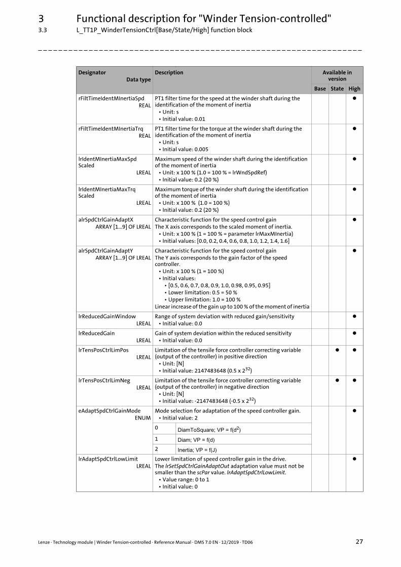
rFiltTimeIdentMInertiaSpdREAL
PT1 filter time for the speed at the winder shaft during the identification of the moment of inertia
• Unit: s• Initial value: 0.01
rFiltTimeIdentMInertiaTrqREAL
PT1 filter time for the torque at the winder shaft during the identification of the moment of inertia
• Unit: s• Initial value: 0.005
lrIdentMInertiaMaxSpdScaled
LREAL
Maximum speed of the winder shaft during the identification of the moment of inertia
• Unit: x 100 % (1.0 = 100 % = lrWndSpdRef)• Initial value: 0.2 (20 %)
lrIdentMInertiaMaxTrqScaled
LREAL
Maximum torque of the winder shaft during the identification of the moment of inertia
• Unit: x 100 % (1.0 = 100 %)• Initial value: 0.2 (20 %)
alrSpdCtrlGainAdaptXARRAY [1...9] OF LREAL
Characteristic function for the speed control gainThe X axis corresponds to the scaled moment of inertia.
• Unit: x 100 % (1 = 100 % = parameter lrMaxMInertia)• Initial values: [0.0, 0.2, 0.4, 0.6, 0.8, 1.0, 1.2, 1.4, 1.6]
alrSpdCtrlGainAdaptYARRAY [1...9] OF LREAL
Characteristic function for the speed control gainThe Y axis corresponds to the gain factor of the speed controller.
• Unit: x 100 % (1 = 100 %)• Initial values:
• [0.5, 0.6, 0.7, 0.8, 0.9, 1.0, 0.98, 0.95, 0.95]• Lower limitation: 0.5 = 50 %• Upper limitation: 1.0 = 100 %
Linear increase of the gain up to 100 % of the moment of inertia
lrReducedGainWindowLREAL
Range of system deviation with reduced gain/sensitivity• Initial value: 0.0
lrReducedGainLREAL
Gain of system deviation within the reduced sensitivity• Initial value: 0.0
lrTensPosCtrlLimPos LREAL
Limitation of the tensile force controller correcting variable (output of the controller) in positive direction
• Unit: [N]• Initial value: 2147483648 (0.5 x 232)
lrTensPosCtrlLimNeg LREAL
Limitation of the tensile force controller correcting variable (output of the controller) in negative direction
• Unit: [N]• Initial value: -2147483648 (-0.5 x 232)
eAdaptSpdCtrlGainModeENUM
Mode selection for adaptation of the speed controller gain.• Initial value: 2
0 DiamToSquare; VP = f(d2)
1 Diam; VP = f(d)
2 Inertia; VP = f(J)
lrAdaptSpdCtrlLowLimitLREAL
Lower limitation of speed controller gain in the drive. The lrSetSpdCtrlGainAdaptOut adaptation value must not be smaller than the scPar value. lrAdaptSpdCtrlLowLimit.
• Value range: 0 to 1• Initial value: 0
DesignatorData type
Description Available in version
Base State High
3 Functional description for "Winder Tension-controlled"3.4 State machine
28 Lenze · Technology module | Winder Tension-controlled · Reference Manual · DMS 7.0 EN · 12/2019 · TD06
_ _ _ _ _ _ _ _ _ _ _ _ _ _ _ _ _ _ _ _ _ _ _ _ _ _ _ _ _ _ _ _ _ _ _ _ _ _ _ _ _ _ _ _ _ _ _ _ _ _ _ _ _ _ _ _ _ _ _ _ _ _ _ _
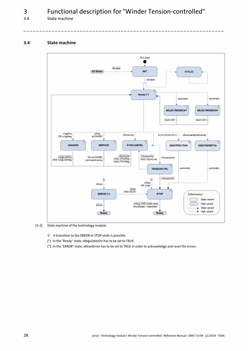
3.4 State machine
[3-2] State machine of the technology module
A transition to the ERROR or STOP state is possible.
(*1 In the "Ready" state, xRegulatorOn has to be set to TRUE.
(*2 In the "ERROR" state, xResetError has to be set to TRUE in order to acknowledge and reset the errors.
Lenze · Technology module | Winder Tension-controlled · Reference Manual · DMS 7.0 EN · 12/2019 · TD06 29
3 Functional description for "Winder Tension-controlled"3.4 State machine
_ _ _ _ _ _ _ _ _ _ _ _ _ _ _ _ _ _ _ _ _ _ _ _ _ _ _ _ _ _ _ _ _ _ _ _ _ _ _ _ _ _ _ _ _ _ _ _ _ _ _ _ _ _ _ _ _ _ _ _ _ _ _ _
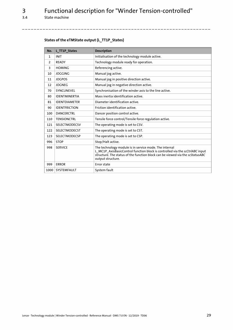
States of the eTMState output (L_TT1P_States)
No. L_TT1P_States Description
1 INIT Initialisation of the technology module active.
2 READY Technology module ready for operation.
3 HOMING Referencing active.
10 JOGGING Manual jog active.
11 JOGPOS Manual jog in positive direction active.
12 JOGNEG Manual jog in negative direction active.
70 SYNCLINEVEL Synchronisation of the winder axis to the line active.
80 IDENTMINERTIA Mass inertia identification active.
81 IDENTDIAMETER Diameter identification active.
90 IDENTFRICTION Friction identification active.
100 DANCERCTRL Dancer position control active.
110 TENSIONCTRL Tensile force control/Tensile force regulation active.
121 SELECTMODECSV The operating mode is set to CSV.
122 SELECTMODECST The operating mode is set to CST.
123 SELECTMODECSP The operating mode is set to CSP.
996 STOP Stop/Halt active.
998 SERVICE The technology module is in service mode. The internal L_MC1P_AxisBasicControl function block is controlled via the scCtrlABC input structure. The status of the function block can be viewed via the scStatusABC output structure.
999 ERROR Error state
1000 SYSTEMFAULT System fault
3 Functional description for "Winder Tension-controlled"3.5 Signal flow diagrams
30 Lenze · Technology module | Winder Tension-controlled · Reference Manual · DMS 7.0 EN · 12/2019 · TD06
_ _ _ _ _ _ _ _ _ _ _ _ _ _ _ _ _ _ _ _ _ _ _ _ _ _ _ _ _ _ _ _ _ _ _ _ _ _ _ _ _ _ _ _ _ _ _ _ _ _ _ _ _ _ _ _ _ _ _ _ _ _ _ _
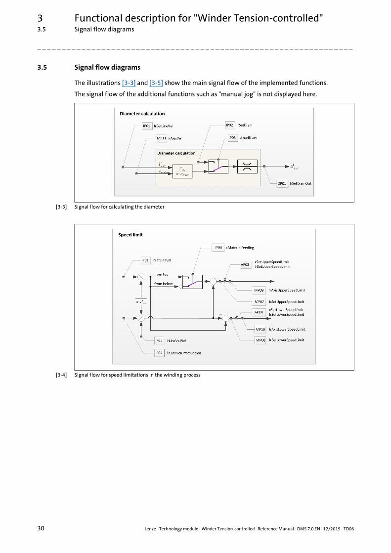
3.5 Signal flow diagrams
The illustrations [3-3] and [3-5] show the main signal flow of the implemented functions.
The signal flow of the additional functions such as "manual jog" is not displayed here.
[3-3] Signal flow for calculating the diameter
[3-4] Signal flow for speed limitations in the winding process

Lenze · Technology module | Winder Tension-controlled · Reference Manual · DMS 7.0 EN · 12/2019 · TD06 31
3 Functional description for "Winder Tension-controlled"3.5 Signal flow diagrams
_ _ _ _ _ _ _ _ _ _ _ _ _ _ _ _ _ _ _ _ _ _ _ _ _ _ _ _ _ _ _ _ _ _ _ _ _ _ _ _ _ _ _ _ _ _ _ _ _ _ _ _ _ _ _ _ _ _ _ _ _ _ _ _
[3-5] Signal flow of the technology module
3 Functional description for "Winder Tension-controlled"3.5 Signal flow diagrams
32 Lenze · Technology module | Winder Tension-controlled · Reference Manual · DMS 7.0 EN · 12/2019 · TD06
_ _ _ _ _ _ _ _ _ _ _ _ _ _ _ _ _ _ _ _ _ _ _ _ _ _ _ _ _ _ _ _ _ _ _ _ _ _ _ _ _ _ _ _ _ _ _ _ _ _ _ _ _ _ _ _ _ _ _ _ _ _ _ _
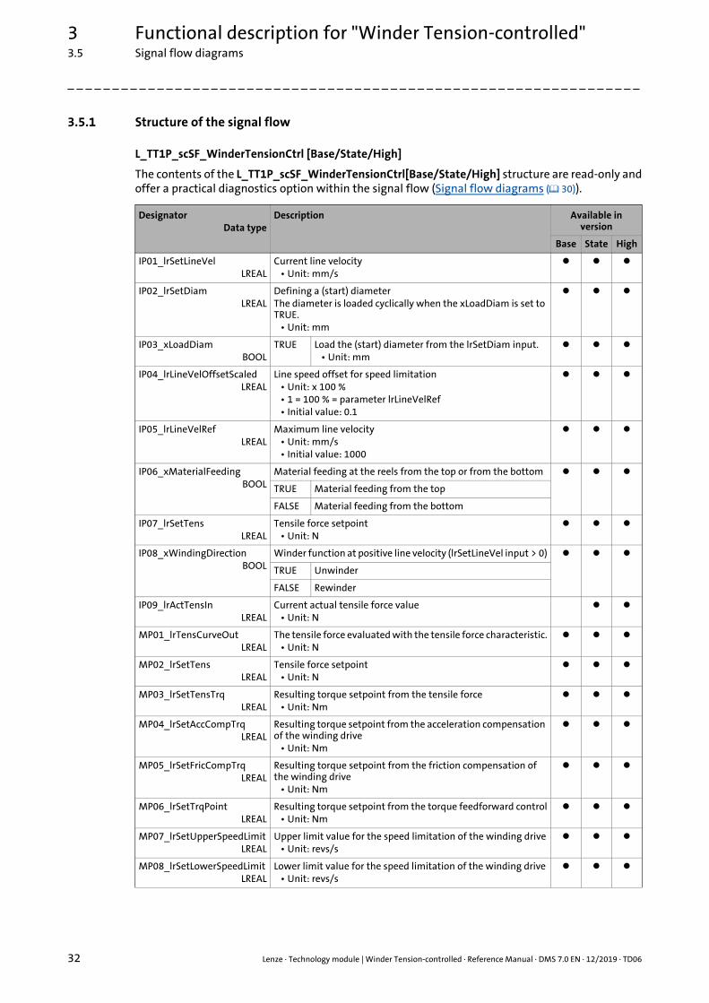
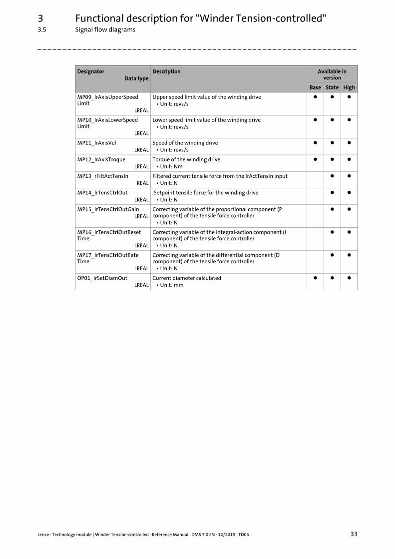
3.5.1 Structure of the signal flow
L_TT1P_scSF_WinderTensionCtrl [Base/State/High]
The contents of the L_TT1P_scSF_WinderTensionCtrl[Base/State/High] structure are read-only andoffer a practical diagnostics option within the signal flow (Signal flow diagrams ( 30)).
DesignatorData type
Description Available in version
Base State High
IP01_lrSetLineVelLREAL
Current line velocity• Unit: mm/s
IP02_lrSetDiamLREAL
Defining a (start) diameterThe diameter is loaded cyclically when the xLoadDiam is set to TRUE.
• Unit: mm
IP03_xLoadDiamBOOL
TRUE Load the (start) diameter from the lrSetDiam input.• Unit: mm
IP04_lrLineVelOffsetScaledLREAL
Line speed offset for speed limitation• Unit: x 100 %• 1 = 100 % = parameter lrLineVelRef• Initial value: 0.1
IP05_lrLineVelRefLREAL
Maximum line velocity• Unit: mm/s• Initial value: 1000
IP06_xMaterialFeedingBOOL
Material feeding at the reels from the top or from the bottom
TRUE Material feeding from the top
FALSE Material feeding from the bottom
IP07_lrSetTensLREAL
Tensile force setpoint• Unit: N
IP08_xWindingDirectionBOOL
Winder function at positive line velocity (lrSetLineVel input > 0)
TRUE Unwinder
FALSE Rewinder
IP09_lrActTensInLREAL
Current actual tensile force value• Unit: N
MP01_lrTensCurveOutLREAL
The tensile force evaluated with the tensile force characteristic.• Unit: N
MP02_lrSetTensLREAL
Tensile force setpoint• Unit: N
MP03_lrSetTensTrqLREAL
Resulting torque setpoint from the tensile force• Unit: Nm
MP04_lrSetAccCompTrqLREAL
Resulting torque setpoint from the acceleration compensation of the winding drive
• Unit: Nm
MP05_lrSetFricCompTrqLREAL
Resulting torque setpoint from the friction compensation of the winding drive
• Unit: Nm
MP06_lrSetTrqPointLREAL
Resulting torque setpoint from the torque feedforward control• Unit: Nm
MP07_lrSetUpperSpeedLimitLREAL
Upper limit value for the speed limitation of the winding drive• Unit: revs/s
MP08_lrSetLowerSpeedLimitLREAL
Lower limit value for the speed limitation of the winding drive• Unit: revs/s
Lenze · Technology module | Winder Tension-controlled · Reference Manual · DMS 7.0 EN · 12/2019 · TD06 33
3 Functional description for "Winder Tension-controlled"3.5 Signal flow diagrams
_ _ _ _ _ _ _ _ _ _ _ _ _ _ _ _ _ _ _ _ _ _ _ _ _ _ _ _ _ _ _ _ _ _ _ _ _ _ _ _ _ _ _ _ _ _ _ _ _ _ _ _ _ _ _ _ _ _ _ _ _ _ _ _
MP09_lrAxisUpperSpeedLimit
LREAL
Upper speed limit value of the winding drive• Unit: revs/s
MP10_lrAxisLowerSpeedLimit
LREAL
Lower speed limit value of the winding drive• Unit: revs/s
MP11_lrAxisVelLREAL
Speed of the winding drive• Unit: revs/s
MP12_lrAxisTroqueLREAL
Torque of the winding drive• Unit: Nm
MP13_rFiltActTensInREAL
Filtered current tensile force from the lrActTensIn input• Unit: N
MP14_lrTensCtrlOutLREAL
Setpoint tensile force for the winding drive• Unit: N
MP15_lrTensCtrlOutGainLREAL
Correcting variable of the proportional component (P component) of the tensile force controller
• Unit: N
MP16_lrTensCtrlOutResetTime
LREAL
Correcting variable of the integral-action component (I component) of the tensile force controller
• Unit: N
MP17_lrTensCtrlOutRateTime
LREAL
Correcting variable of the differential component (D component) of the tensile force controller
• Unit: N
OP01_lrSetDiamOutLREAL
Current diameter calculated• Unit: mm
DesignatorData type
Description Available in version
Base State High
3 Functional description for "Winder Tension-controlled"3.5 Signal flow diagrams
34 Lenze · Technology module | Winder Tension-controlled · Reference Manual · DMS 7.0 EN · 12/2019 · TD06
_ _ _ _ _ _ _ _ _ _ _ _ _ _ _ _ _ _ _ _ _ _ _ _ _ _ _ _ _ _ _ _ _ _ _ _ _ _ _ _ _ _ _ _ _ _ _ _ _ _ _ _ _ _ _ _ _ _ _ _ _ _ _ _
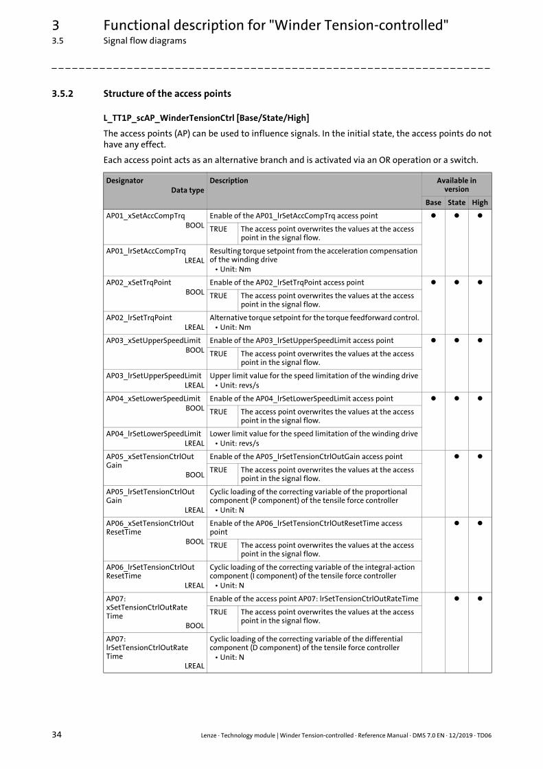
3.5.2 Structure of the access points
L_TT1P_scAP_WinderTensionCtrl [Base/State/High]
The access points (AP) can be used to influence signals. In the initial state, the access points do nothave any effect.
Each access point acts as an alternative branch and is activated via an OR operation or a switch.
DesignatorData type
Description Available in version
Base State High
AP01_xSetAccCompTrqBOOL
Enable of the AP01_lrSetAccCompTrq access point
TRUE The access point overwrites the values at the access point in the signal flow.
AP01_lrSetAccCompTrqLREAL
Resulting torque setpoint from the acceleration compensation of the winding drive
• Unit: Nm
AP02_xSetTrqPointBOOL
Enable of the AP02_lrSetTrqPoint access point
TRUE The access point overwrites the values at the access point in the signal flow.
AP02_lrSetTrqPointLREAL
Alternative torque setpoint for the torque feedforward control.• Unit: Nm
AP03_xSetUpperSpeedLimitBOOL
Enable of the AP03_lrSetUpperSpeedLimit access point
TRUE The access point overwrites the values at the access point in the signal flow.
AP03_lrSetUpperSpeedLimitLREAL
Upper limit value for the speed limitation of the winding drive• Unit: revs/s
AP04_xSetLowerSpeedLimitBOOL
Enable of the AP04_lrSetLowerSpeedLimit access point
TRUE The access point overwrites the values at the access point in the signal flow.
AP04_lrSetLowerSpeedLimitLREAL
Lower limit value for the speed limitation of the winding drive• Unit: revs/s
AP05_xSetTensionCtrlOutGain
BOOL
Enable of the AP05_lrSetTensionCtrlOutGain access point
TRUE The access point overwrites the values at the access point in the signal flow.
AP05_lrSetTensionCtrlOutGain
LREAL
Cyclic loading of the correcting variable of the proportional component (P component) of the tensile force controller
• Unit: N
AP06_xSetTensionCtrlOutResetTime
BOOL
Enable of the AP06_lrSetTensionCtrlOutResetTime access point
TRUE The access point overwrites the values at the access point in the signal flow.
AP06_lrSetTensionCtrlOutResetTime
LREAL
Cyclic loading of the correcting variable of the integral-action component (I component) of the tensile force controller
• Unit: N
AP07:xSetTensionCtrlOutRateTime
BOOL
Enable of the access point AP07: lrSetTensionCtrlOutRateTime
TRUE The access point overwrites the values at the access point in the signal flow.
AP07:lrSetTensionCtrlOutRateTime
LREAL
Cyclic loading of the correcting variable of the differential component (D component) of the tensile force controller
• Unit: N
Lenze · Technology module | Winder Tension-controlled · Reference Manual · DMS 7.0 EN · 12/2019 · TD06 35
3 Functional description for "Winder Tension-controlled"3.5 Signal flow diagrams
_ _ _ _ _ _ _ _ _ _ _ _ _ _ _ _ _ _ _ _ _ _ _ _ _ _ _ _ _ _ _ _ _ _ _ _ _ _ _ _ _ _ _ _ _ _ _ _ _ _ _ _ _ _ _ _ _ _ _ _ _ _ _ _
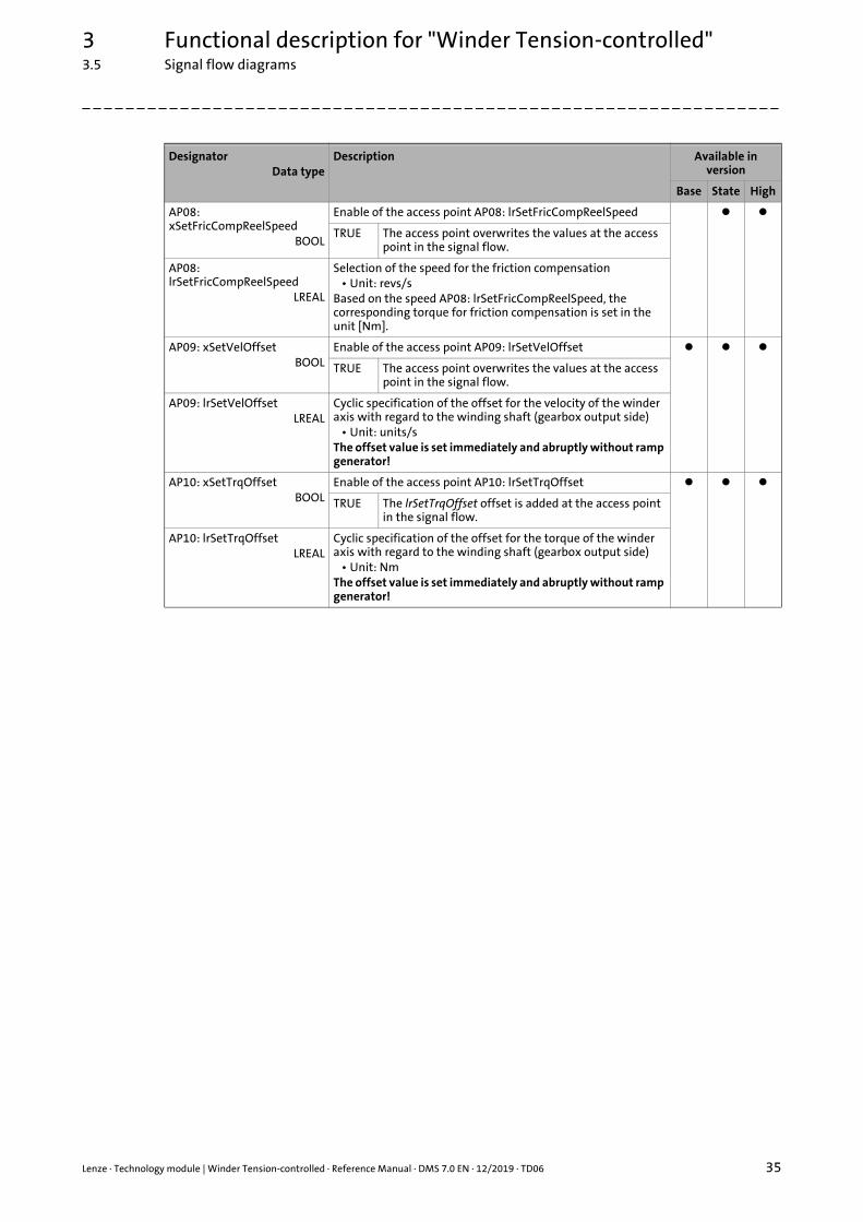
AP08: xSetFricCompReelSpeed
BOOL
Enable of the access point AP08: lrSetFricCompReelSpeed
TRUE The access point overwrites the values at the access point in the signal flow.
AP08: lrSetFricCompReelSpeed
LREAL
Selection of the speed for the friction compensation• Unit: revs/s
Based on the speed AP08: lrSetFricCompReelSpeed, the corresponding torque for friction compensation is set in the unit [Nm].
AP09: xSetVelOffsetBOOL
Enable of the access point AP09: lrSetVelOffset
TRUE The access point overwrites the values at the access point in the signal flow.
AP09: lrSetVelOffsetLREAL
Cyclic specification of the offset for the velocity of the winder axis with regard to the winding shaft (gearbox output side)
• Unit: units/sThe offset value is set immediately and abruptly without ramp generator!
AP10: xSetTrqOffsetBOOL
Enable of the access point AP10: lrSetTrqOffset
TRUE The lrSetTrqOffset offset is added at the access point in the signal flow.
AP10: lrSetTrqOffsetLREAL
Cyclic specification of the offset for the torque of the winder axis with regard to the winding shaft (gearbox output side)
• Unit: NmThe offset value is set immediately and abruptly without ramp generator!
DesignatorData type
Description Available in version
Base State High
3 Functional description for "Winder Tension-controlled"3.6 Defining the winding direction (winding/unwinding)
36 Lenze · Technology module | Winder Tension-controlled · Reference Manual · DMS 7.0 EN · 12/2019 · TD06
_ _ _ _ _ _ _ _ _ _ _ _ _ _ _ _ _ _ _ _ _ _ _ _ _ _ _ _ _ _ _ _ _ _ _ _ _ _ _ _ _ _ _ _ _ _ _ _ _ _ _ _ _ _ _ _ _ _ _ _ _ _ _ _
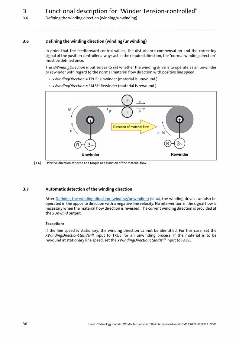
3.6 Defining the winding direction (winding/unwinding)
In order that the feedforward control values, the disturbance compensation and the correctingsignal of the position controller always act in the required direction, the "normal winding direction"must be defined once.
The xWindingDirection input serves to set whether the winding drive is to operate as an unwinderor rewinder with regard to the normal material flow direction with positive line speed.
• xWindingDirection = TRUE: Unwinder (material is unwound.)
• xWindingDirection = FALSE: Rewinder (material is rewound.)
[3-6] Effective direction of speed and torque as a function of the material flow
3.7 Automatic detection of the winding direction
After Defining the winding direction (winding/unwinding) ( 36), the winding drives can also beoperated in the opposite direction with a negative line velocity. No intervention in the signal flow isnecessary when the material flow direction is reversed. The current winding direction is provided atthe xUnwind output.
Exception:
If the line speed is stationary, the winding direction cannot be identified. For this case, set thexWindingDirectionStandstill input to TRUE for an unwinding process. If the material is to berewound at stationary line speed, set the xWindingDirectionStandstill input to FALSE.
Lenze · Technology module | Winder Tension-controlled · Reference Manual · DMS 7.0 EN · 12/2019 · TD06 37
3 Functional description for "Winder Tension-controlled"3.8 Defining the material feed to the winder
_ _ _ _ _ _ _ _ _ _ _ _ _ _ _ _ _ _ _ _ _ _ _ _ _ _ _ _ _ _ _ _ _ _ _ _ _ _ _ _ _ _ _ _ _ _ _ _ _ _ _ _ _ _ _ _ _ _ _ _ _ _ _ _
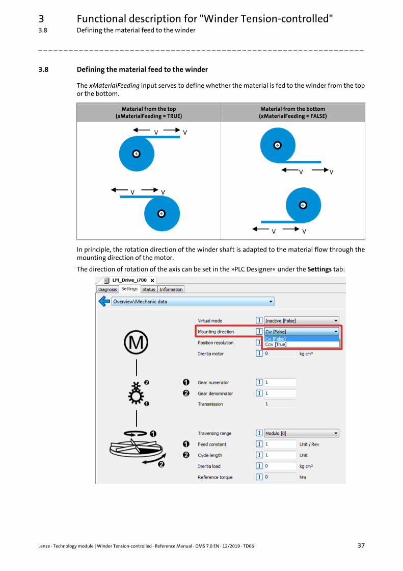
3.8 Defining the material feed to the winder
The xMaterialFeeding input serves to define whether the material is fed to the winder from the topor the bottom.
In principle, the rotation direction of the winder shaft is adapted to the material flow through themounting direction of the motor.
The direction of rotation of the axis can be set in the »PLC Designer« under the Settings tab:
Material from the top(xMaterialFeeding = TRUE)
Material from the bottom(xMaterialFeeding = FALSE)
3 Functional description for "Winder Tension-controlled"3.9 Master value source for diameter calculation
38 Lenze · Technology module | Winder Tension-controlled · Reference Manual · DMS 7.0 EN · 12/2019 · TD06
_ _ _ _ _ _ _ _ _ _ _ _ _ _ _ _ _ _ _ _ _ _ _ _ _ _ _ _ _ _ _ _ _ _ _ _ _ _ _ _ _ _ _ _ _ _ _ _ _ _ _ _ _ _ _ _ _ _ _ _ _ _ _ _
3.9 Master value source for diameter calculation
The technology module always operates with the line velocity at the lrSetLineVel input.
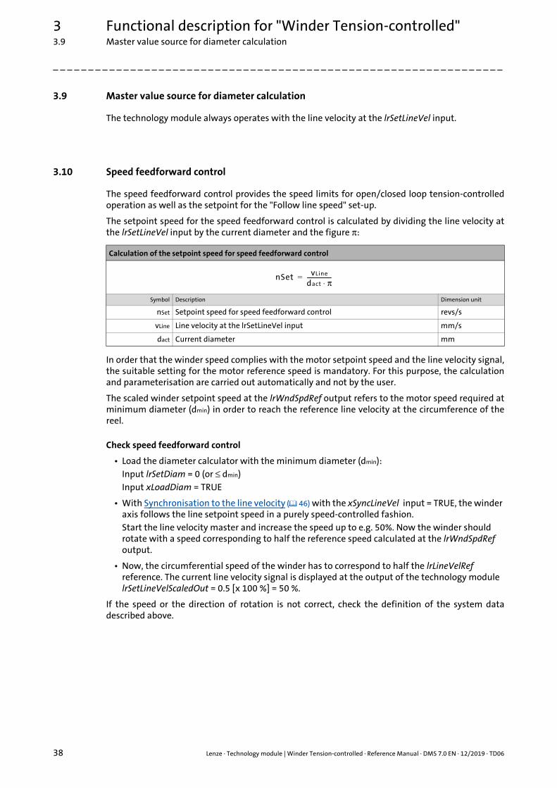
3.10 Speed feedforward control
The speed feedforward control provides the speed limits for open/closed loop tension-controlledoperation as well as the setpoint for the "Follow line speed" set-up.
The setpoint speed for the speed feedforward control is calculated by dividing the line velocity atthe lrSetLineVel input by the current diameter and the figure π:
In order that the winder speed complies with the motor setpoint speed and the line velocity signal,the suitable setting for the motor reference speed is mandatory. For this purpose, the calculationand parameterisation are carried out automatically and not by the user.
The scaled winder setpoint speed at the lrWndSpdRef output refers to the motor speed required atminimum diameter (dmin) in order to reach the reference line velocity at the circumference of thereel.
Check speed feedforward control
• Load the diameter calculator with the minimum diameter (dmin):Input lrSetDiam = 0 (or ≤ dmin)Input xLoadDiam = TRUE
• With Synchronisation to the line velocity ( 46) with the xSyncLineVel input = TRUE, the winder axis follows the line setpoint speed in a purely speed-controlled fashion.Start the line velocity master and increase the speed up to e.g. 50%. Now the winder should rotate with a speed corresponding to half the reference speed calculated at the lrWndSpdRef output.
• Now, the circumferential speed of the winder has to correspond to half the lrLineVelRef reference. The current line velocity signal is displayed at the output of the technology module lrSetLineVelScaledOut = 0.5 [x 100 %] = 50 %.
If the speed or the direction of rotation is not correct, check the definition of the system datadescribed above.
Calculation of the setpoint speed for speed feedforward control
Symbol Description Dimension unit
nSet Setpoint speed for speed feedforward control revs/s
vLine Line velocity at the lrSetLineVel input mm/s
dact Current diameter mm
nSet vLine
dact π⋅-----------------=

Lenze · Technology module | Winder Tension-controlled · Reference Manual · DMS 7.0 EN · 12/2019 · TD06 39
3 Functional description for "Winder Tension-controlled"3.11 Calculation of the diameter
_ _ _ _ _ _ _ _ _ _ _ _ _ _ _ _ _ _ _ _ _ _ _ _ _ _ _ _ _ _ _ _ _ _ _ _ _ _ _ _ _ _ _ _ _ _ _ _ _ _ _ _ _ _ _ _ _ _ _ _ _ _ _ _
3.11 Calculation of the diameter
The current diameter is calculated by dividing the line velocity by the winder speed and the figure π:
In fact, however, for the calculation integrated speed values are used instead of instantaneousvalues. This causes a average determination. The number of revolutions causing a recalculation ofthe diameter is specified via the parameter lrDiamCalcRegularDist. The initial value of thisparameter is set to 1 winding shaft revolution.
For quick diameter changes of lrDiamCalcRegularDist, it can be switched to the fast calculationmode by setting the xDiamCalcReduced input = TRUE. The lower calculation distance is set with thelrDiamCalcReducedDist parameter. Here, the initial value 1/10 is defined for the winder shaftrevolution.
The smaller calculation distance is also activated automatically when a starting diameter is loaded.This state remains until a new diameter has been calculated. The function is required if the realdiameter of the reel may deviate significantly from the loaded diameter. Thus, the winder shaft onlyrotates for a short distance with the "wrong" diameter. After the diameter has been calculated, asuitable value is available again.
Parameters to be set
The parameters for diameter calculation are located in the L_TT1P_scPar_WinderTensionCtrl [Base/State/High] ( 23) parameter structure.
Calculation of the current diameter
Symbol Description Dimension unit
dact Current diameter mm
vLine Line velocity mm/s
nWinder Winder speed revs/s
lrDiamCalcRegularDist : LREAL := 1;lrDiamCalcReducedDist : LREAL := 0.1;
dactvLine
nWinder π⋅---------------------------=
3 Functional description for "Winder Tension-controlled"3.12 Holding the diameter
40 Lenze · Technology module | Winder Tension-controlled · Reference Manual · DMS 7.0 EN · 12/2019 · TD06
_ _ _ _ _ _ _ _ _ _ _ _ _ _ _ _ _ _ _ _ _ _ _ _ _ _ _ _ _ _ _ _ _ _ _ _ _ _ _ _ _ _ _ _ _ _ _ _ _ _ _ _ _ _ _ _ _ _ _ _ _ _ _ _
3.12 Holding the diameter
For some operating states of the winder, in which the line velocity does not correspond to thecircumferential velocity of the reel, the current diameter cannot be calculated from the line velocityand the motor speed. In this case, the calculation of new values must be prevented and the diametermust be held at the old value.
This is done automatically under the following conditions:
• Line velocity < minimum line velocity(lrMinLineVel [mm/s] from the L_TT1P_scPar_WinderTensionCtrl [Base/State/High] ( 23)) parameter structure;
• Winder speed < lrMinLineVel [mm/s] / (π x d [mm]);
• In the states STOP, ERROR, READY, JOGGING and SYNCLINEVEL.
For the user holding of the diameter, set the xHoldDiam input to TRUE.
Lenze · Technology module | Winder Tension-controlled · Reference Manual · DMS 7.0 EN · 12/2019 · TD06 41
3 Functional description for "Winder Tension-controlled"3.13 Defining the diameter / signal from the diameter sensor
_ _ _ _ _ _ _ _ _ _ _ _ _ _ _ _ _ _ _ _ _ _ _ _ _ _ _ _ _ _ _ _ _ _ _ _ _ _ _ _ _ _ _ _ _ _ _ _ _ _ _ _ _ _ _ _ _ _ _ _ _ _ _ _
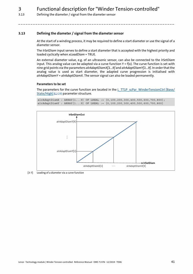
3.13 Defining the diameter / signal from the diameter sensor
At the start of a winding process, it may be required to define a start diameter or use the signal of adiameter sensor.
The lrSetDiam input serves to define a start diameter that is accepted with the highest priority andloaded cyclically when xLoadDiam = TRUE.
An external diameter value, e.g. of an ultrasonic sensor, can also be connected to the lrSetDiaminput. This analog value can be adapted via a curve function Y = f(x). The curve function is set withnine grid points via the parameters alrAdaptDiamX[1...9] and alrAdaptDiamY[1...9]. In order that theanalog value is used as start diameter, the adapted curve progression is initialised withalrAdaptDiamY = alrAdaptDiamX. The sensor signal can also be loaded permanently.
Parameters to be set
The parameters for the curve function are located in the L_TT1P_scPar_WinderTensionCtrl [Base/State/High] ( 23) parameter structure.
[3-7] Loading of a diameter via a curve function
alrAdaptDiamX : ARRAY[1...9] OF LREAL := [0,100,200,300,400,500,600,700,800]; alrAdaptDiamY : ARRAY[1...9] OF LREAL := [0,100,200,300,400,500,600,700,800]
3 Functional description for "Winder Tension-controlled"3.14 Material length counter
42 Lenze · Technology module | Winder Tension-controlled · Reference Manual · DMS 7.0 EN · 12/2019 · TD06
_ _ _ _ _ _ _ _ _ _ _ _ _ _ _ _ _ _ _ _ _ _ _ _ _ _ _ _ _ _ _ _ _ _ _ _ _ _ _ _ _ _ _ _ _ _ _ _ _ _ _ _ _ _ _ _ _ _ _ _ _ _ _ _
3.14 Material length counter
The material length counter is activated with the xEnable input = TRUE.
The material length is calculated by integrating the line speed at the lrSetLineVel input and is shownat the lrMaterialCounter output (in millimetres). Depending on the Defining the winding direction(winding/unwinding) ( 36), the material length is incremented or decremented.
For the analog signal of the line speed, the current value of the material length can be filtered witha PT1 characteristic. The filter time is set with the rFiltTimeMaterialCounter parameter (the defaultsetting is '0 ms').
The current value of the material length is stored in the persistent data in the PersistentVarstructure.
For the initialisation of the material length, an initial material length can be set via thelrSetMaterialPos parameter. With a FALSETRUE edge at the xSetMaterialCounter input, the initialmaterial length is accepted with the highest priority.
Parameters to be set
The parameters for the material length counter are located in the L_TT1P_scPar_WinderTensionCtrl[Base/State/High] ( 23) parameter structure.
rFiltTimeMaterialCounter : LREAL := 0;lrSetMaterialPos : REAL := 0;
Lenze · Technology module | Winder Tension-controlled · Reference Manual · DMS 7.0 EN · 12/2019 · TD06 43
3 Functional description for "Winder Tension-controlled"3.15 Sources for the material length counting
_ _ _ _ _ _ _ _ _ _ _ _ _ _ _ _ _ _ _ _ _ _ _ _ _ _ _ _ _ _ _ _ _ _ _ _ _ _ _ _ _ _ _ _ _ _ _ _ _ _ _ _ _ _ _ _ _ _ _ _ _ _ _ _
3.15 Sources for the material length counting
The material length can be counted from one of three different sources, and the counting procedurecan be carried out in two different ways.
3.15.1 Source: "lrSetLineVel" input
Prerequisites
• No reference axis is connected to the MaterialCounterAxis input.
• xLineVelDiamCalc parameter = FALSE
Operating principle
In addition to the position (lrSetMaterialPos parameter), the line speed is integrated into thematerial length counting process at the lrSetLineVel input. The resulting value is shown as materiallength at the lrMaterialCounter output and is stored persistently.
With a FALSETRUE edge at the xSetMaterialCounter input, the material length is loaded from thelrSetMaterialPos parameter, directly setting the material length to the value of lrSetMaterialPos atthe lrMaterialCounter output. The values from the continuing counting process are added to thevalue of the material length set at the output.
3.15.2 Source: "lrSetLineVelDiamCalc" input
Prerequisites
• No reference axis is connected to the MaterialCounterAxis input.
• xLineVelDiamCalc parameter = TRUE
Operating principle
In addition to the position (lrSetMaterialPos parameter), the line speed for the Calculation of thediameter ( 39) is integrated into the material length counting process at the lrSetLineVelDiamCalcinput. The resulting value is shown as material length at the lrMaterialCounter output and is storedpersistently.
With a FALSETRUE edge at the xSetMaterialCounter input, the material length is loaded from thelrSetMaterialPos parameter, directly setting the material length to the value of lrSetMaterialPos atthe lrMaterialCounter output. The values from the continuing counting process are added to thevalue of the material length set at the output.
Note!
In the case of a noisy signal, the material counting process is falsified by integration of the line speed. In this process, the material length counter shows a drift, even if the line is stable.
Note!
In the case of a noisy signal, the material counting process is falsified by integration of the line speed. In this process, the material length counter shows a drift, even if the line is stable.
3 Functional description for "Winder Tension-controlled"3.15 Sources for the material length counting
44 Lenze · Technology module | Winder Tension-controlled · Reference Manual · DMS 7.0 EN · 12/2019 · TD06
_ _ _ _ _ _ _ _ _ _ _ _ _ _ _ _ _ _ _ _ _ _ _ _ _ _ _ _ _ _ _ _ _ _ _ _ _ _ _ _ _ _ _ _ _ _ _ _ _ _ _ _ _ _ _ _ _ _ _ _ _ _ _ _
3.15.3 Source: "MaterialCounterAxis" input (reference axis)
Prerequisites
• A reference axis (modulo axis) is connected to the MaterialCounterAxis input.
• The loss-free number of revolutions determined is used as a basis for the material length counting. – This procedure is suitable for noisy signals!
Operating principle
Via the feed constant of the reference axis (modulo axis), the material length is shown at thelrMaterialCounter output.
The number of revolutions counted can be read out via the MP20_liRevCounter measuring point.The fractional amount of a revolution is shown via the MP21_lrRevCounterResidual measuringpoint. The values of these measuring points are stored persistently.
With a FALSETRUE edge at the xSetMaterialCounter input, the material length is loaded from thelrSetMaterialPos parameter. In this process, the material length is converted to the number ofrevolutions and stored via the feed constant of the axis.
The material length from the lrSetMaterialPos parameter is shown at the lrMaterialCounter output.
Note!
An exact material length counting process can only be carried out with a slip-free measuring wheel. A measuring wheel that is prone to slip on the material causes errors in the material length counting.
Lenze · Technology module | Winder Tension-controlled · Reference Manual · DMS 7.0 EN · 12/2019 · TD06 45
3 Functional description for "Winder Tension-controlled"3.16 Manual jog (jogging)
_ _ _ _ _ _ _ _ _ _ _ _ _ _ _ _ _ _ _ _ _ _ _ _ _ _ _ _ _ _ _ _ _ _ _ _ _ _ _ _ _ _ _ _ _ _ _ _ _ _ _ _ _ _ _ _ _ _ _ _ _ _ _ _
3.16 Manual jog (jogging)
For the manual jog of the winder, the lrJogLineVel manual jog velocity is used.
When the xJogLinePos = TRUE, the line is driven in positive direction and when the xJogLineNeg =TRUE, it is driven in negative direction. The line is driven as long as the input remains set to TRUE.The running travel command cannot be replaced by the other jog command.
The parameterisable setpoints lrJogLineVel, lrJogLineAcc and lrJogLineDec for manual jog refer to thecircumferential velocity or line velocity and not to the motor speed.
Parameters to be set
The parameters for the manual jog are located in the L_TT1P_scPar_WinderTensionCtrl [Base/State/High] ( 23) parameter structure.
The parameter values can be changed during operation. They are accepted when resetting theinputs xJogLinePos = TRUE or xJogLineNeg = TRUE.
lrLineJerk : LREAL := 10000; // Jerk [mm/s^3]lrJogLineVel : LREAL := 100; // Velocity [mm/s]lrJogLineAcc : LREAL := 100; // Acceleration [mm/s^2]lrJogLineDec : LREAL := 10; // Deceleration [mm/s^2]

3 Functional description for "Winder Tension-controlled"3.17 Synchronisation to the line velocity
46 Lenze · Technology module | Winder Tension-controlled · Reference Manual · DMS 7.0 EN · 12/2019 · TD06
_ _ _ _ _ _ _ _ _ _ _ _ _ _ _ _ _ _ _ _ _ _ _ _ _ _ _ _ _ _ _ _ _ _ _ _ _ _ _ _ _ _ _ _ _ _ _ _ _ _ _ _ _ _ _ _ _ _ _ _ _ _ _ _
3.17 Synchronisation to the line velocity
The winder axis is synchronised to the line velocity when the xSyncLineVel input is set to TRUE.
The parameters lrSyncLineAcc and lrSyncLineDec refer to the circumferential velocity or line velocityand not to the motor speed.
Parameters to be set
The parameters for synchronising to the line velocity are located in theL_TT1P_scPar_WinderTensionCtrl [Base/State/High] ( 23) parameter structure.
lrLineJerk : LREAL := 10000; // Jerk [mm/s^3]lrSyncLineAcc : LREAL := 100; // Acceleration [mm/s^2]lrSyncLineDec : LREAL := 100; // Deceleration [mm/s^2]
Lenze · Technology module | Winder Tension-controlled · Reference Manual · DMS 7.0 EN · 12/2019 · TD06 47
3 Functional description for "Winder Tension-controlled"3.18 Trimming
_ _ _ _ _ _ _ _ _ _ _ _ _ _ _ _ _ _ _ _ _ _ _ _ _ _ _ _ _ _ _ _ _ _ _ _ _ _ _ _ _ _ _ _ _ _ _ _ _ _ _ _ _ _ _ _ _ _ _ _ _ _ _ _
3.18 Trimming
When the xTrimLinePos input = TRUE, the line is trimmed in positive direction and when thexTrimLineNeg input = TRUE, the line is trimmed in negative direction.
For trimming, the lrTrimLineVel trimming velocity is added to the lrSetLineVel line velocity. In thetrimming process, the overall setpoint can exceed the trimming setpoint maximally by the value ofthe minimum line velocity.
The parameterisable setpoints lrTrimLineVel, lrTrimLineAcc and lrTrimLineDec for the positive andnegative trimming operation refer to the circumferential velocity or line velocity and not to themotor speed.
Parameters to be set
The parameters for trimming are located in the L_TT1P_scPar_WinderTensionCtrl [Base/State/High] ( 23) parameter structure.
Note!
Trimming can only be used if the winder axis is synchronised to the line velocity.
Synchronisation to the line velocity ( 46)
lrLineJerk : LREAL := 10000; // Jerk [mm/s^3]lrTrimLineVel : LREAL := 100; // Velocity [mm/s]lrTrimLineAcc : LREAL := 100; // Acceleration [mm/s^2]lrTrimLineDec : LREAL := 10; // Deceleration [mm/s^2]
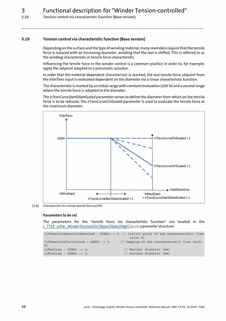
3 Functional description for "Winder Tension-controlled"3.19 Tension control via characteristic function (Base version)
48 Lenze · Technology module | Winder Tension-controlled · Reference Manual · DMS 7.0 EN · 12/2019 · TD06
_ _ _ _ _ _ _ _ _ _ _ _ _ _ _ _ _ _ _ _ _ _ _ _ _ _ _ _ _ _ _ _ _ _ _ _ _ _ _ _ _ _ _ _ _ _ _ _ _ _ _ _ _ _ _ _ _ _ _ _ _ _ _ _
3.19 Tension control via characteristic function (Base version)
Depending on the surface and the type of winding material, many rewinders require that the tensileforce is reduced with an increasing diameter, avoiding that the reel is shifted. This is referred to asthe winding characteristic or tensile force characteristic.
Influencing the tensile force in the winder control is a common practice in order to, for example,apply the setpoint adapted to a pneumatic actuator.
In order that the material-dependent characteristic is reached, the real tensile force setpoint fromthe lrSetTens input is evaluated dependent on the diameter via a linear characteristic function.
The characteristic is marked by an initial range with constant evaluation (100 %) and a second rangewhere the tensile force is adapted to the diameter.
The lrTensCurveStartDiamScaled parameter serves to define the diameter from which on the tensileforce is to be reduced. The lrTensCurveCtrlScaled parameter is used to evaluate the tensile force atthe maximum diameter.
[3-8] Characteristic for a linear tensile force profile
Parameters to be set
The parameters for the "tensile force via characteristic function" are located in theL_TT1P_scPar_WinderTensionCtrl [Base/State/High] ( 23) parameter structure.
lrTensCurveStartDiamScaled : LREAL := 0; // Initial point of the characteristic line [x100 %]lrTensCurveCtrlScaled : LREAL := 0; // Gapping of the characteristic line [x100 %]lrMaxDiam : LREAL := 0; // Maximal diameter [mm]lrMinDiam : LREAL := 0; // minimum diameter [mm]
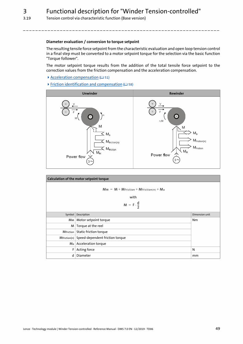
Lenze · Technology module | Winder Tension-controlled · Reference Manual · DMS 7.0 EN · 12/2019 · TD06 49
3 Functional description for "Winder Tension-controlled"3.19 Tension control via characteristic function (Base version)
_ _ _ _ _ _ _ _ _ _ _ _ _ _ _ _ _ _ _ _ _ _ _ _ _ _ _ _ _ _ _ _ _ _ _ _ _ _ _ _ _ _ _ _ _ _ _ _ _ _ _ _ _ _ _ _ _ _ _ _ _ _ _ _
Diameter evaluation / conversion to torque setpoint
The resulting tensile force setpoint from the characteristic evaluation and open loop tension controlin a final step must be converted to a motor setpoint torque for the selection via the basic function"Torque follower".
The motor setpoint torque results from the addition of the total tensile force setpoint to thecorrection values from the friction compensation and the acceleration compensation.
Acceleration compensation ( 51)
Friction identification and compensation ( 58)
Unwinder Rewinder
Calculation of the motor setpoint torque
with
Symbol Description Dimension unit
MM Motor setpoint torque Nm
M Torque at the reel
Mfriction Static friction torque
Mfriction(n) Speed-dependent friction torque
Ma Acceleration torque
F Acting force N
d Diameter mm
MM M Mfriction Mfriction n( ) Ma+ + +=
M Fd2---⋅=

3 Functional description for "Winder Tension-controlled"3.19 Tension control via characteristic function (Base version)
50 Lenze · Technology module | Winder Tension-controlled · Reference Manual · DMS 7.0 EN · 12/2019 · TD06
_ _ _ _ _ _ _ _ _ _ _ _ _ _ _ _ _ _ _ _ _ _ _ _ _ _ _ _ _ _ _ _ _ _ _ _ _ _ _ _ _ _ _ _ _ _ _ _ _ _ _ _ _ _ _ _ _ _ _ _ _ _ _ _
Ramp generator for the tensile force setpoint
After having activated open loop tension control with the xTensCtrl input = TRUE, the tensile forcemust first reach the setpoint from the lrSetTens input. In order that the tensile force is increased ina controlled fashion, the ramp generator for the tensile force setpoint is loaded with the value 'zero'first. The ramp is set using the lrTensRamp parameter in unit [N/s]. The standard setting of the rampis preselected with lrTensRamp = 1. If the ramp generator reaches the setpoint, the xDone output isset to TRUE.
The parameters for the ramp generator are located in the L_TT1P_scPar_WinderTensionCtrl [Base/State/High] ( 23) parameter structure.
lrTensRef : LREAL := 2; // 100% of line tension [N]lrTensRamp : LREAL := 1; // Ramp of tension values [N/s]

Lenze · Technology module | Winder Tension-controlled · Reference Manual · DMS 7.0 EN · 12/2019 · TD06 51
3 Functional description for "Winder Tension-controlled"3.20 Acceleration compensation
_ _ _ _ _ _ _ _ _ _ _ _ _ _ _ _ _ _ _ _ _ _ _ _ _ _ _ _ _ _ _ _ _ _ _ _ _ _ _ _ _ _ _ _ _ _ _ _ _ _ _ _ _ _ _ _ _ _ _ _ _ _ _ _
3.20 Acceleration compensation
The acceleration in the line velocity setpoint is a disturbance in the winding process. The torqueconsumed for acceleration is lacking for the tensile force.
Therefore the acceleration torque has to be calculated and pilot-controlled as an additional torque.
In this connection, the change of the speed value (new value – old value) corresponds to theacceleration of the winder. The winder speed is calculated from the line velocity.
In practice, it must be expected that the line velocity signal will not be ideally constant. Theparameters lrAccCmpsGainAcc and lrAccCmpsGainDec can be used to set the resolution of the signalto be differentiated. Additionally, the signal first can be smoothed via a PT1 functionality. The PT1time constant is set via the rFiltTimeAccSpd parameter. For noise suppression, a lagging range canbe interconnected via the calculated acceleration torque. The lagging range is set via thelrAccCmpsDeadBandTrqScaled parameter in the unit [x 100 %].
The acceleration compensation is enabled when the xAccCmp input = TRUE.
In order to generate acceleration, the line velocity must be differentiated. Depending on theresolution and the stability of the signal, it may be required to reduce the sensitivity of thedifferentiation to prevent that master value fluctuations cause sudden acceleration changes.Different material widths or material densities can be taken into account as percentage via thelrMInertiaAdapt input.
Calculation of the acceleration torque
with
Symbol Description Dimension unit
Ma Acceleration torque Nm
/n (Delta) motor speed δ revs/s
/t (Delta ) time s
Jconst Constant moment of inertia kgm2
Jvar Variable (diameter-dependent) moment of inertia
Jmax Maximum moment of inertia
dact Current diameter mm
dmin Minimum diameter (sleeve diameter)
dmax Maximum diameter
B Material width mm
Ma 2 π ∂n∂t------ Jconst Jvar+( )⋅ ⋅ ⋅=
Jvar Jmax Jconst–( ) dact4 dmin4–dmax4 dmin4–----------------------------------- B⋅ ⋅=
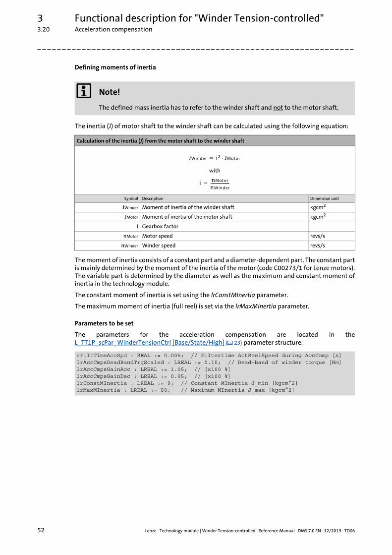
3 Functional description for "Winder Tension-controlled"3.20 Acceleration compensation
52 Lenze · Technology module | Winder Tension-controlled · Reference Manual · DMS 7.0 EN · 12/2019 · TD06
_ _ _ _ _ _ _ _ _ _ _ _ _ _ _ _ _ _ _ _ _ _ _ _ _ _ _ _ _ _ _ _ _ _ _ _ _ _ _ _ _ _ _ _ _ _ _ _ _ _ _ _ _ _ _ _ _ _ _ _ _ _ _ _
Defining moments of inertia
The inertia (J) of motor shaft to the winder shaft can be calculated using the following equation:
The moment of inertia consists of a constant part and a diameter-dependent part. The constant partis mainly determined by the moment of the inertia of the motor (code C00273/1 for Lenze motors).The variable part is determined by the diameter as well as the maximum and constant moment ofinertia in the technology module.
The constant moment of inertia is set using the lrConstMInertia parameter.
The maximum moment of inertia (full reel) is set via the lrMaxMInertia parameter.
Parameters to be set
The parameters for the acceleration compensation are located in theL_TT1P_scPar_WinderTensionCtrl [Base/State/High] ( 23) parameter structure.
Note!
The defined mass inertia has to refer to the winder shaft and not to the motor shaft.
Calculation of the inertia (J) from the motor shaft to the winder shaft
with
Symbol Description Dimension unit
JWinder Moment of inertia of the winder shaft kgcm2
JMotor Moment of inertia of the motor shaft kgcm2
I Gearbox factor
nMotor Motor speed revs/s
nWinder Winder speed revs/s
rFiltTimeAccSpd : REAL := 0.005; // Filtertime ActReelSpeed during AccComp [s]lrAccCmpsDeadBandTrqScaled : LREAL := 0.10; // Dead-band of winder torque [Nm]lrAccCmpsGainAcc : LREAL := 1.05; // [x100 %]lrAccCmpsGainDec : LREAL := 0.95; // [x100 %]lrConstMInertia : LREAL := 9; // Constant MInertia J_min [kgcm^2]lrMaxMInertia : LREAL := 50; // Maximum MInertia J_max [kgcm^2]
JWinder i2 JMotor⋅=
i nMotor
nWinder-------------------=
Lenze · Technology module | Winder Tension-controlled · Reference Manual · DMS 7.0 EN · 12/2019 · TD06 53
3 Functional description for "Winder Tension-controlled"3.21 Web break monitoring
_ _ _ _ _ _ _ _ _ _ _ _ _ _ _ _ _ _ _ _ _ _ _ _ _ _ _ _ _ _ _ _ _ _ _ _ _ _ _ _ _ _ _ _ _ _ _ _ _ _ _ _ _ _ _ _ _ _ _ _ _ _ _ _
3.21 Web break monitoring
For the diameter calculation, the technology module provides a web break monitoring function.
In case of a web break, the calculated diameter changes contrary to the winding direction(unwinding or rewinding).
The monitoring function is activated with the xWebBreakMonit input = TRUE, making a diameterchange opposed to the winding direction only permissible within the window set in thelrWebBreakWindow parameter.
Rewinding or unwinding is automatically detected via the sign of the line velocity and the windingdirection set via the xWindingDirection input.
Parameters to be set
The parameters for web break monitoring are located in the L_TT1P_scPar_WinderTensionCtrl[Base/State/High] ( 23) parameter structure.
Note!
Web break monitoring may only be activated when the calculated diameter corresponds to the real diameter.
If web break monitoring is activated (xWebBreakMonit = TRUE), a diameter change contrary to the winding direction specified via the xUnwind output.
After loading a starting diameter which deviates considerably from the real diameter contrary to the winding direction, this may lead to an unintentional triggering of the monitoring function. If, for instance, a starting diameter of 50% is loaded for a rewinder and the real diameter only is 45%, then a change of the diameter value to the real 45% is prevented when web break monitoring is activated.
lrWebBreakWindow : LREAL := 0.1; // Window for web break 0..1 [x100 %]

3 Functional description for "Winder Tension-controlled"3.22 Persistent variables
54 Lenze · Technology module | Winder Tension-controlled · Reference Manual · DMS 7.0 EN · 12/2019 · TD06
_ _ _ _ _ _ _ _ _ _ _ _ _ _ _ _ _ _ _ _ _ _ _ _ _ _ _ _ _ _ _ _ _ _ _ _ _ _ _ _ _ _ _ _ _ _ _ _ _ _ _ _ _ _ _ _ _ _ _ _ _ _ _ _
3.22 Persistent variables
The technology module provides the possibility of persistently saving the parameters determinedsuch as the winding diameter. For this purpose, the following setting has to be made in the »PLCDesigner« for the technology module.
How to create persistent variables in the »PLC Designer«:
Note!
This procedure does not apply to the Application Template, since it already provides structures for persistent data of the machine modules.
1. Add the global list for managing persistent variables in the context menu to Application with the Add object Persistent variables... command.
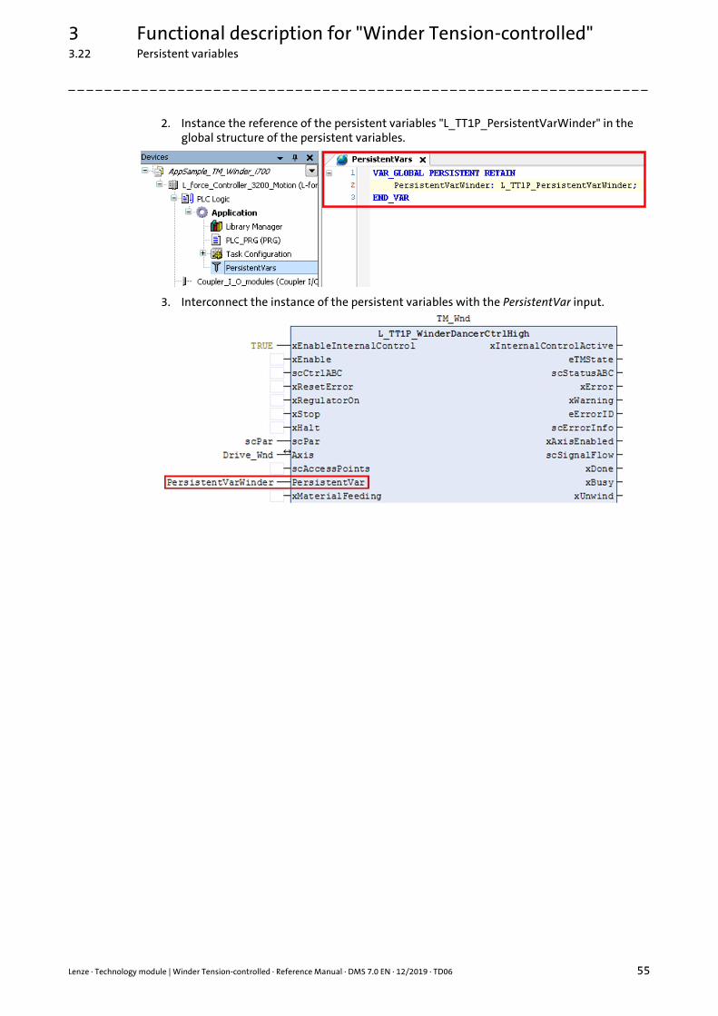
Lenze · Technology module | Winder Tension-controlled · Reference Manual · DMS 7.0 EN · 12/2019 · TD06 55
3 Functional description for "Winder Tension-controlled"3.22 Persistent variables
_ _ _ _ _ _ _ _ _ _ _ _ _ _ _ _ _ _ _ _ _ _ _ _ _ _ _ _ _ _ _ _ _ _ _ _ _ _ _ _ _ _ _ _ _ _ _ _ _ _ _ _ _ _ _ _ _ _ _ _ _ _ _ _
2. Instance the reference of the persistent variables "L_TT1P_PersistentVarWinder" in the global structure of the persistent variables.
3. Interconnect the instance of the persistent variables with the PersistentVar input.
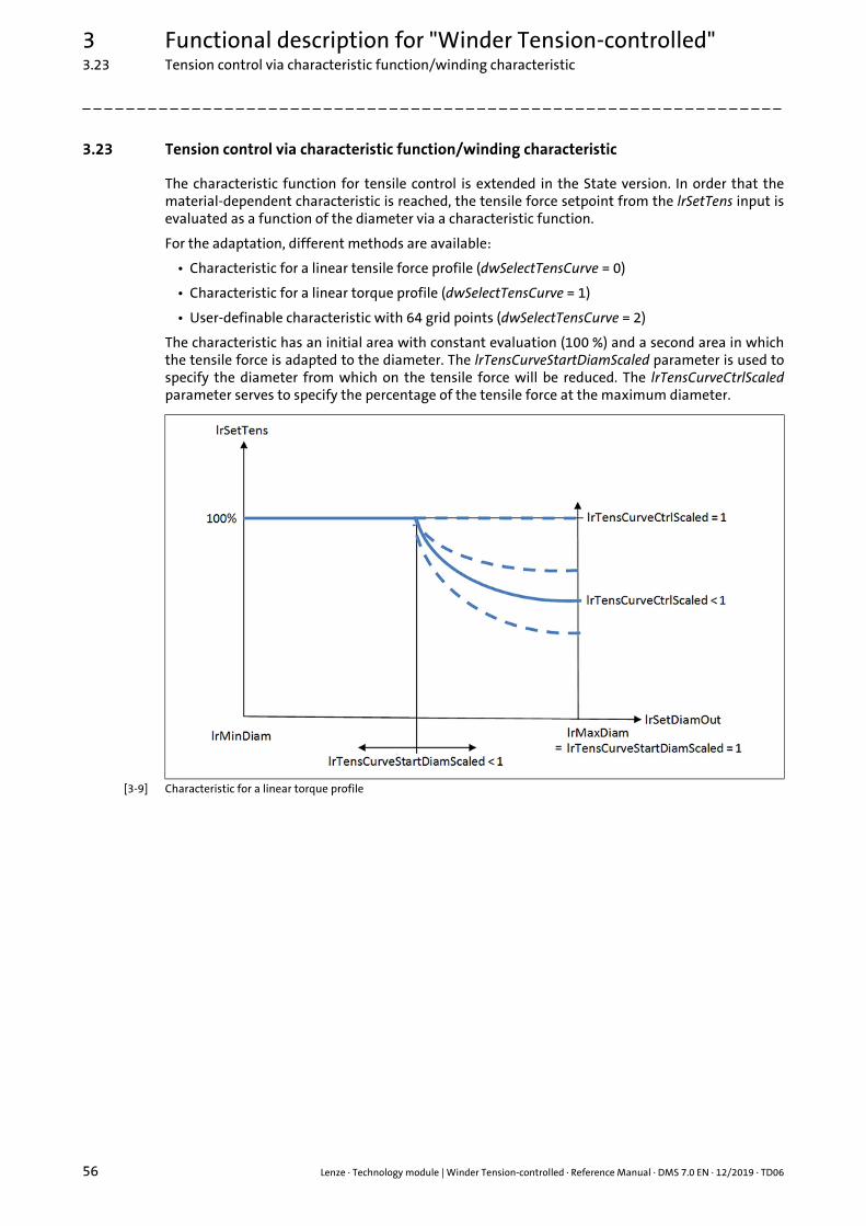
3 Functional description for "Winder Tension-controlled"3.23 Tension control via characteristic function/winding characteristic
56 Lenze · Technology module | Winder Tension-controlled · Reference Manual · DMS 7.0 EN · 12/2019 · TD06
_ _ _ _ _ _ _ _ _ _ _ _ _ _ _ _ _ _ _ _ _ _ _ _ _ _ _ _ _ _ _ _ _ _ _ _ _ _ _ _ _ _ _ _ _ _ _ _ _ _ _ _ _ _ _ _ _ _ _ _ _ _ _ _
3.23 Tension control via characteristic function/winding characteristic
The characteristic function for tensile control is extended in the State version. In order that thematerial-dependent characteristic is reached, the tensile force setpoint from the lrSetTens input isevaluated as a function of the diameter via a characteristic function.
For the adaptation, different methods are available:
• Characteristic for a linear tensile force profile (dwSelectTensCurve = 0)
• Characteristic for a linear torque profile (dwSelectTensCurve = 1)
• User-definable characteristic with 64 grid points (dwSelectTensCurve = 2)
The characteristic has an initial area with constant evaluation (100 %) and a second area in whichthe tensile force is adapted to the diameter. The lrTensCurveStartDiamScaled parameter is used tospecify the diameter from which on the tensile force will be reduced. The lrTensCurveCtrlScaledparameter serves to specify the percentage of the tensile force at the maximum diameter.
[3-9] Characteristic for a linear torque profile
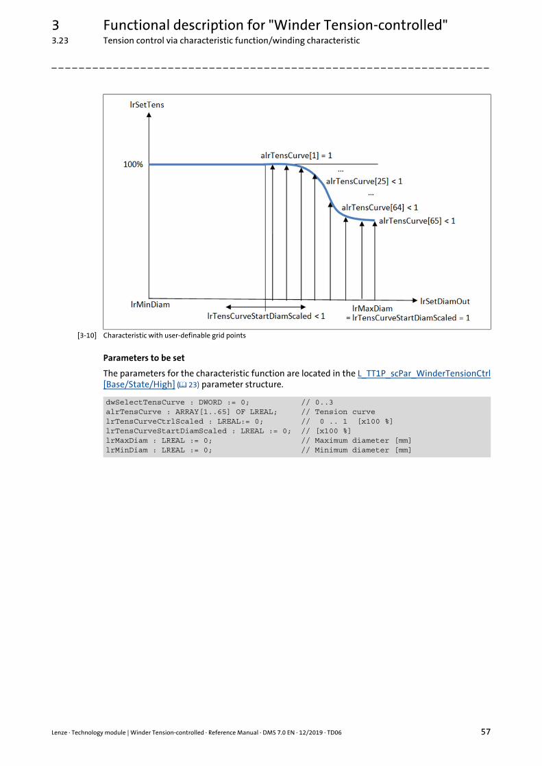
Lenze · Technology module | Winder Tension-controlled · Reference Manual · DMS 7.0 EN · 12/2019 · TD06 57
3 Functional description for "Winder Tension-controlled"3.23 Tension control via characteristic function/winding characteristic
_ _ _ _ _ _ _ _ _ _ _ _ _ _ _ _ _ _ _ _ _ _ _ _ _ _ _ _ _ _ _ _ _ _ _ _ _ _ _ _ _ _ _ _ _ _ _ _ _ _ _ _ _ _ _ _ _ _ _ _ _ _ _ _
[3-10] Characteristic with user-definable grid points
Parameters to be set
The parameters for the characteristic function are located in the L_TT1P_scPar_WinderTensionCtrl[Base/State/High] ( 23) parameter structure.
dwSelectTensCurve : DWORD := 0; // 0..3alrTensCurve : ARRAY[1..65] OF LREAL; // Tension curvelrTensCurveCtrlScaled : LREAL:= 0; // 0 .. 1 [x100 %]lrTensCurveStartDiamScaled : LREAL := 0; // [x100 %]lrMaxDiam : LREAL := 0; // Maximum diameter [mm]lrMinDiam : LREAL := 0; // Minimum diameter [mm]
3 Functional description for "Winder Tension-controlled"3.24 Friction identification and compensation
58 Lenze · Technology module | Winder Tension-controlled · Reference Manual · DMS 7.0 EN · 12/2019 · TD06
_ _ _ _ _ _ _ _ _ _ _ _ _ _ _ _ _ _ _ _ _ _ _ _ _ _ _ _ _ _ _ _ _ _ _ _ _ _ _ _ _ _ _ _ _ _ _ _ _ _ _ _ _ _ _ _ _ _ _ _ _ _ _ _
3.24 Friction identification and compensation
To identify the friction, the winder shaft must be empty (without containing material).
Use the setting lrIdentFricMaxSpdScaled parameter = 1 to define the maximum motor speed (100 %)relating to the maximum winder speed at the lrWndSpdRef output, which may be reached duringthe identification run. (Usually the motor will also reach the lrWndSpdRef speed with the minimumdiameter and at maximum line speed.)
Adapt the acceleration and deceleration time for the identification run to the basic conditionsgiven: The maximally attainable torque must suffice to accelerate the mass inertia at the ramp tothe lrIdentFricMaxSpdScaled parameter.
Optionally up to 4 friction characteristics can be recorded and stored. A change-over betweendifferent friction characteristics is for instance required when variable speed drives are used.
The friction characteristic is detected with a rising edge (FALSETRUE) at the xExecuteIdentFricinput.
Termination of the identification
The identification is completed as soon as the motor has reached standstill again, no errors havebeen reported and xDone has been set to TRUE.
The detected torque setpoints can be checked for plausibility and can be corrected if required.
The friction compensation is activated with xFricCmps = TRUE.
Parameters to be set
The parameters for friction identification and compensation are located in theL_TT1P_scPar_WinderTensionCtrl [Base/State/High] ( 23) parameter structure.
Note!
If the winder is controlled via an oil-filled gearbox, the friction very much depends on the temperature of the oil. The friction identification should be carried out using gearbox oil that is as warm as possible. For this it is sufficient to previously actuate the motor in a speed-controlled manner for some minutes.
lrFricCurveStartTrq : LREAL := 0; // Start friction for linear compensation [Nm]lrFricCurveEndTrq : LREAL := 0; // End friction for linear compensation [Nm]rFiltTimeFricSetSpd : REAL := 0.01; // Filter time SetReelSpeed 1 = 1[s]lrIdentFricMaxSpdScaled : LREAL := 0.9; // Max. speed for ident friction [x100%]lrIdentFricAccDec : LREAL := 1; // Acceleration/Deceleration for ident // friction [rev/s^2]rFiltTimeIdentFricSpd : REAL := 0.0; // Filter time ident ActReelSpeed 1 = 1[s]rFiltTimeIdentFricTrq : REAL := 0.05; // Filter time 1 = 1[s]dwSelectFricCurve : DWORD:=1; // Friction curve 0..4
Lenze · Technology module | Winder Tension-controlled · Reference Manual · DMS 7.0 EN · 12/2019 · TD06 59
3 Functional description for "Winder Tension-controlled"3.25 PI controller for tension control
_ _ _ _ _ _ _ _ _ _ _ _ _ _ _ _ _ _ _ _ _ _ _ _ _ _ _ _ _ _ _ _ _ _ _ _ _ _ _ _ _ _ _ _ _ _ _ _ _ _ _ _ _ _ _ _ _ _ _ _ _ _ _ _
3.25 PI controller for tension control
Activation of the tension control with the xTensCtrl input = TRUE initiates closed-loop control to anactual tensile force value.
Use the lrTensCtrlInfluence input to define the influence of the PI controller on the motor control(standard setting: 0 %).
After having activated open loop tension control, the tensile force must first reach the setpoint fromthe lrSetTens input. In order that the tensile force is increased in a controlled fashion, the rampgenerator for the tensile force setpoint is loaded with the current actual tensile force value first. Theramp is set using the lrTensRamp parameter in the unit [N/s]. The standard setting of the ramp ispreselected with lrTensRamp = 1. If the ramp generator reaches the setpoint, the xDone output isset to TRUE.
It is not possible to filter and/or adapt the actual tensile force value. A signal (actual tensile forcevalue) at the lrActTensIn input is expected.
The I component of the PI controller can be set with the lrTensCtrlResetTime parameter. In thedefault setting, lrTensCtrlResetTime is set to 0 (deactivated).
The correcting variable from the I component can be brought to zero by means of the ramp withxResetCtrl = TRUE and can be maintained at zero. If the xResetCtrl input is set to TRUE, the Icomponent is always deactivated.
The controller gain is set with the lrTensCtrlGain parameter.
The correcting variable of the tensile force controller can be limited in positive direction via thelrTensPosCtrlLimPos [N] parameter and in negative direction via the lrTensPosCtrlLimNeg [N]parameter.
Parameters to be set
The parameters for the PI controller and for tension control are located in theL_TT1P_scPar_WinderTensionCtrl [Base/State/High] ( 23) parameter structure.
lrTensRamp : LREAL := 1; // Ramp of lrSetTens [N/s]lrTensCtrlGain : LREAL := 1; // Gain of tension controllrTensCtrlResetTime : LREAL := 0; // Reset time of tension controllrTensPosCtrlLimPos: LREAL := 2147483648 (0.5 x 232)lrTensPosCtrlLimNeg: LREAL := -2147483648 (0.5 x 232)
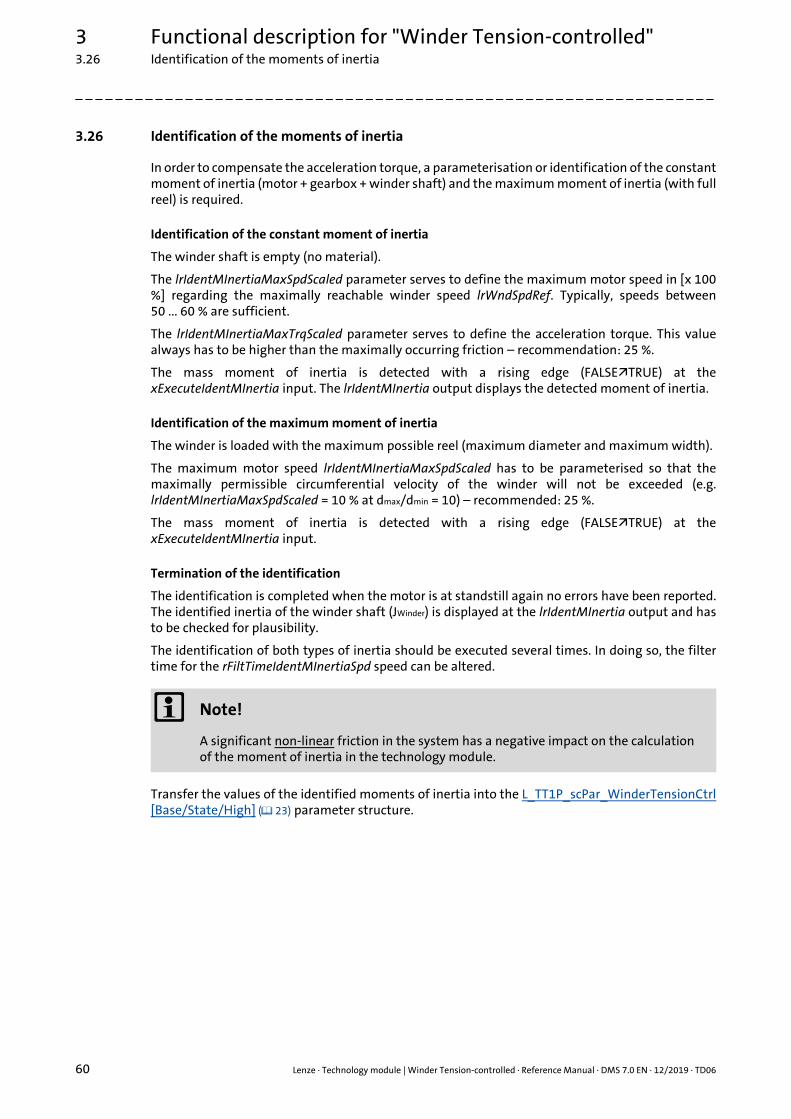
3 Functional description for "Winder Tension-controlled"3.26 Identification of the moments of inertia
60 Lenze · Technology module | Winder Tension-controlled · Reference Manual · DMS 7.0 EN · 12/2019 · TD06
_ _ _ _ _ _ _ _ _ _ _ _ _ _ _ _ _ _ _ _ _ _ _ _ _ _ _ _ _ _ _ _ _ _ _ _ _ _ _ _ _ _ _ _ _ _ _ _ _ _ _ _ _ _ _ _ _ _ _ _ _ _ _ _
3.26 Identification of the moments of inertia
In order to compensate the acceleration torque, a parameterisation or identification of the constantmoment of inertia (motor + gearbox + winder shaft) and the maximum moment of inertia (with fullreel) is required.
Identification of the constant moment of inertia
The winder shaft is empty (no material).
The lrIdentMInertiaMaxSpdScaled parameter serves to define the maximum motor speed in [x 100%] regarding the maximally reachable winder speed lrWndSpdRef. Typically, speeds between50 ... 60 % are sufficient.
The lrIdentMInertiaMaxTrqScaled parameter serves to define the acceleration torque. This valuealways has to be higher than the maximally occurring friction – recommendation: 25 %.
The mass moment of inertia is detected with a rising edge (FALSETRUE) at thexExecuteIdentMInertia input. The lrIdentMInertia output displays the detected moment of inertia.
Identification of the maximum moment of inertia
The winder is loaded with the maximum possible reel (maximum diameter and maximum width).
The maximum motor speed lrIdentMInertiaMaxSpdScaled has to be parameterised so that themaximally permissible circumferential velocity of the winder will not be exceeded (e.g.lrIdentMInertiaMaxSpdScaled = 10 % at dmax/dmin = 10) – recommended: 25 %.
The mass moment of inertia is detected with a rising edge (FALSETRUE) at thexExecuteIdentMInertia input.
Termination of the identification
The identification is completed when the motor is at standstill again no errors have been reported.The identified inertia of the winder shaft (JWinder) is displayed at the lrIdentMInertia output and hasto be checked for plausibility.
The identification of both types of inertia should be executed several times. In doing so, the filtertime for the rFiltTimeIdentMInertiaSpd speed can be altered.
Transfer the values of the identified moments of inertia into the L_TT1P_scPar_WinderTensionCtrl[Base/State/High] ( 23) parameter structure.
Note!
A significant non-linear friction in the system has a negative impact on the calculation of the moment of inertia in the technology module.
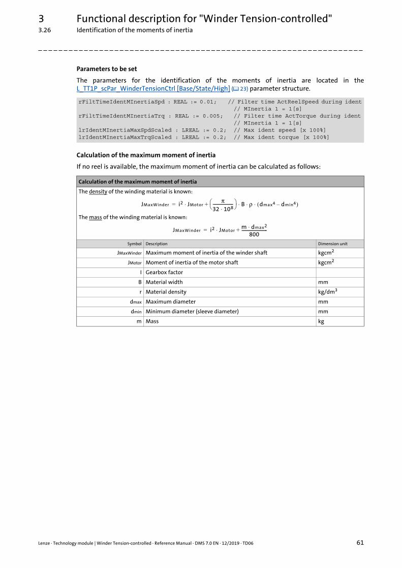
Lenze · Technology module | Winder Tension-controlled · Reference Manual · DMS 7.0 EN · 12/2019 · TD06 61
3 Functional description for "Winder Tension-controlled"3.26 Identification of the moments of inertia
_ _ _ _ _ _ _ _ _ _ _ _ _ _ _ _ _ _ _ _ _ _ _ _ _ _ _ _ _ _ _ _ _ _ _ _ _ _ _ _ _ _ _ _ _ _ _ _ _ _ _ _ _ _ _ _ _ _ _ _ _ _ _ _
Parameters to be set
The parameters for the identification of the moments of inertia are located in theL_TT1P_scPar_WinderTensionCtrl [Base/State/High] ( 23) parameter structure.
Calculation of the maximum moment of inertia
If no reel is available, the maximum moment of inertia can be calculated as follows:
rFiltTimeIdentMInertiaSpd : REAL := 0.01; // Filter time ActReelSpeed during ident // MInertia 1 = 1[s]rFiltTimeIdentMInertiaTrq : REAL := 0.005; // Filter time ActTorque during ident // MInertia 1 = 1[s]lrIdentMInertiaMaxSpdScaled : LREAL := 0.2; // Max ident speed [x 100%]lrIdentMInertiaMaxTrqScaled : LREAL := 0.2; // Max ident torque [x 100%]
Calculation of the maximum moment of inertia
The density of the winding material is known:
The mass of the winding material is known:
Symbol Description Dimension unit
JMaxWinder Maximum moment of inertia of the winder shaft kgcm2
JMotor Moment of inertia of the motor shaft kgcm2
I Gearbox factor
B Material width mm
r Material density kg/dm3
dmax Maximum diameter mm
dmin Minimum diameter (sleeve diameter) mm
m Mass kg
JMaxWinder i2 JMotorπ
32 108⋅--------------------
B ρ dmax4 dmin4–( )⋅ ⋅ ⋅+⋅=
JMaxWinder i2 JMotorm dmax2⋅
800-------------------------+⋅=

3 Functional description for "Winder Tension-controlled"3.27 Adaptation of the speed controller gain
62 Lenze · Technology module | Winder Tension-controlled · Reference Manual · DMS 7.0 EN · 12/2019 · TD06
_ _ _ _ _ _ _ _ _ _ _ _ _ _ _ _ _ _ _ _ _ _ _ _ _ _ _ _ _ _ _ _ _ _ _ _ _ _ _ _ _ _ _ _ _ _ _ _ _ _ _ _ _ _ _ _ _ _ _ _ _ _ _ _
3.27 Adaptation of the speed controller gain
Prerequisites
• The winder axis must be enabled (input xRegulatorOn = TRUE).
Activating/Deactivating adaption of the speed controller gain
The adaption of the speed controller gain is independent of the state of the TM and from a currentlyexecuted function and can therefore be activated or deactivated at any time.
Input scPar.xAdaptSpdCtrlGain = TRUE: Adaption of speed controller gain activated.
Input scPar.xAdaptSpdCtrlGain = FALSE: Adaption of speed controller gain deactivated.
Operating principle
The value for the adaption is calculated in the TM, whereby the calculation regulation is specifiedvia the scPar.eAdaptSpdCtrlGainMode adaption mode (see below).
Range for the value of adaption: 0 ... 1 (1 = 100 % of the speed gain from the setting of the speedcontroller)
The resulting adaption value set in the speed controller can be influenced multiplicatively with afactor from the scPar.lrAdaptSpdCtrlGainFactor input.
The smallest permissible value for adaption of the speed controller gain is defined via thescPar.lrAdaptSpdCtrlLowLimit parameter.
3.27.1 Adaption mode eAdaptSpdCtrlGainMode:= 0 (DiamToSquare)
In mode eAdaptSpdCtrlGainMode:= 0, the adaption is calculated from the scaled diameter(outputlrSetDiamScaledOut) for the square.
[3-11] Adaption of the speed controller depending on the diameter for the square under the influence of lrAdaptSpdCtrlGainFactor
Adaption value = 1 is set for the maximum diameter. The lower limit for the adaption of the speedcontroller gain is defined via the scPar.lrAdaptSpdCtrlLowLimit parameter.

Lenze · Technology module | Winder Tension-controlled · Reference Manual · DMS 7.0 EN · 12/2019 · TD06 63
3 Functional description for "Winder Tension-controlled"3.27 Adaptation of the speed controller gain
_ _ _ _ _ _ _ _ _ _ _ _ _ _ _ _ _ _ _ _ _ _ _ _ _ _ _ _ _ _ _ _ _ _ _ _ _ _ _ _ _ _ _ _ _ _ _ _ _ _ _ _ _ _ _ _ _ _ _ _ _ _ _ _
3.27.2 Adaption mode eAdaptSpdCtrlGainMode:= 1 (Diam)
In mode eAdaptSpdCtrlGainMode:= 1, the speed controller adaption is calculated proportionally tothe scaled diameter (output lrSetDiamScaledOut).
[3-12] Adaption of the speed controller depending on the diameter under the influence of lrAdaptSpdCtrlGainFactor
Adaption value = 1 is set for the maximum diameter. The lower limit for the adaption of the speedcontroller is defined via the lrAdaptSpdCtrlLowLimit parameter.
3.27.3 Adaption mode eAdaptSpdCtrlGainMode:= 2 (Inertia)
In an ideal winder drive model, the motor and reels are seen as a fixed one-mass system. Theoptimal gain of the speed controller thereby behaves in direct proportion to the mass moment of
inertia J with a d4 function.
Since the moment of inertia usually changes significantly during the winding process, for a goodcontrol response it may be necessary to continuously adapt the gain of the speed controller to themoment of inertia.
The specification of mass intertias is required for the mode eAdaptSpdCtrlGainMode:= 2 (Inertia):
• Mass inertia of empty reel scPar.lrConstMInertia with minimum diameter scPar.lrMinDiam
• Mass inertia of the reels with material scPar.lrMaxMInertia for maximum diameter scPar.lrMaxDiam
The mass inertia can either be calculated or identified from the TM. Identification of the momentsof inertia ( 60)
When the two scPar.lrConstMInertia and scPar.lrMaxMInertia mass inertias are known, the adaptionis defined using the following characteristic:

3 Functional description for "Winder Tension-controlled"3.27 Adaptation of the speed controller gain
64 Lenze · Technology module | Winder Tension-controlled · Reference Manual · DMS 7.0 EN · 12/2019 · TD06
_ _ _ _ _ _ _ _ _ _ _ _ _ _ _ _ _ _ _ _ _ _ _ _ _ _ _ _ _ _ _ _ _ _ _ _ _ _ _ _ _ _ _ _ _ _ _ _ _ _ _ _ _ _ _ _ _ _ _ _ _ _ _ _
Preset characteristic function for adaption of the speed controller depending on the masses
The standard setting of this characteristic function is based on the following functions:
• Lower limitation of the adaptation: 50 %
• Upper limitation of the adaptation: 100 %
• Linear increase of the gain up to 100 % of the moment of inertia
Parameters to be set
The characteristic can be changed or completely redetermined via the configuration.
The parameters to be set are found in the scPar structure:
alrSpdCtrlGainAdaptX : ARRAY[1..9] OF LREAL := [0.0, 0.2, 0.4, 0.6, 0.8, 1.0, 1.2, 1.4, 1.6];alrSpdCtrlGainAdaptY : ARRAY[1..9] OF LREAL := [0.5, 0.6, 0.7, 0.8, 0.9, 1.0, 0.98, 0.95, 0.95];
Lenze · Technology module | Winder Tension-controlled · Reference Manual · DMS 7.0 EN · 12/2019 · TD06 65
3 Functional description for "Winder Tension-controlled"3.28 System deviation within the reduced sensitivity
_ _ _ _ _ _ _ _ _ _ _ _ _ _ _ _ _ _ _ _ _ _ _ _ _ _ _ _ _ _ _ _ _ _ _ _ _ _ _ _ _ _ _ _ _ _ _ _ _ _ _ _ _ _ _ _ _ _ _ _ _ _ _ _
3.28 System deviation within the reduced sensitivity
A reduced controller dynamics at low system deviations serves to have a positive effect on thedamping behaviour of the control loop.
The system deviation results from the difference of the values from the lrSetTens input andlrActTensIn.
The lrReducedGainWindow parameter serves to set a tolerance zone in which the system deviationis transmitted to the controller with a lower gain. The tolerance zone is set above and below aroundthe setpoint (lrSetDancerPosScaled input).
The lrReducedGain parameter serves to set the value to which the gain is to be reduced in thedefined tolerance zone. This means, in the tolerance zone, the reduced gain is active(lrReducedGain).
Parameters to be set
The parameters for the characteristic function are located in the L_TT1P_scPar_WinderTensionCtrl[Base/State/High] ( 23) parameter structure.
lrReducedGain : LREAL := 0;lrReducedGainWindow : LREAL := 0;
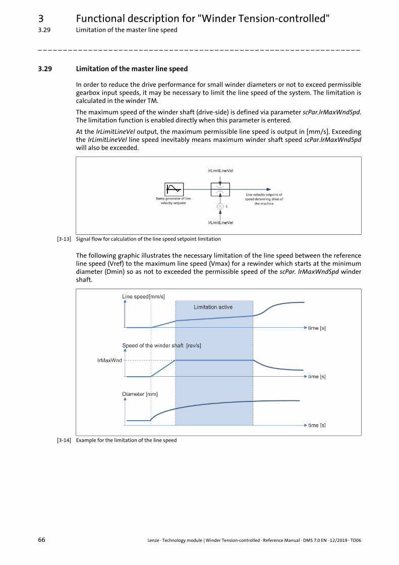
3 Functional description for "Winder Tension-controlled"3.29 Limitation of the master line speed
66 Lenze · Technology module | Winder Tension-controlled · Reference Manual · DMS 7.0 EN · 12/2019 · TD06
_ _ _ _ _ _ _ _ _ _ _ _ _ _ _ _ _ _ _ _ _ _ _ _ _ _ _ _ _ _ _ _ _ _ _ _ _ _ _ _ _ _ _ _ _ _ _ _ _ _ _ _ _ _ _ _ _ _ _ _ _ _ _ _
3.29 Limitation of the master line speed
In order to reduce the drive performance for small winder diameters or not to exceed permissiblegearbox input speeds, it may be necessary to limit the line speed of the system. The limitation iscalculated in the winder TM.
The maximum speed of the winder shaft (drive-side) is defined via parameter scPar.lrMaxWndSpd.The limitation function is enabled directly when this parameter is entered.
At the lrLimitLineVel output, the maximum permissible line speed is output in [mm/s]. Exceedingthe lrLimitLineVel line speed inevitably means maximum winder shaft speed scPar.lrMaxWndSpdwill also be exceeded.
[3-13] Signal flow for calculation of the line speed setpoint limitation
The following graphic illustrates the necessary limitation of the line speed between the referenceline speed (Vref) to the maximum line speed (Vmax) for a rewinder which starts at the minimumdiameter (Dmin) so as not to exceeded the permissible speed of the scPar. lrMaxWndSpd windershaft.
[3-14] Example for the limitation of the line speed

Lenze · Technology module | Winder Tension-controlled · Reference Manual · DMS 7.0 EN · 12/2019 · TD06 67
3 Functional description for "Winder Tension-controlled"3.30 CPU utilisation (example Controller 3231 C)
_ _ _ _ _ _ _ _ _ _ _ _ _ _ _ _ _ _ _ _ _ _ _ _ _ _ _ _ _ _ _ _ _ _ _ _ _ _ _ _ _ _ _ _ _ _ _ _ _ _ _ _ _ _ _ _ _ _ _ _ _ _ _ _
3.30 CPU utilisation (example Controller 3231 C)
The following table shows the CPU utilisation in microseconds using the example of the 3231 Ccontroller (ATOM™ processor, 1.6 GHz).
Variant Wiring of the technology module CPU utilisation
Average Maximum peak
Base xEnable := TRUE;xRegulatorOn := TRUE;xSyncLineVel := TRUE;
75 μs 110 μs
State xEnable := TRUE;xRegulatorOn := TRUE;xSyncLineVel := TRUE;
85 μs 119 μs
High xEnable := TRUE;xRegulatorOn := TRUE;xSyncLineVel := TRUE;
95 μs 122 μs
Index
68 Lenze · Technology module | Winder Tension-controlled · Reference Manual · DMS 7.0 EN · 12/2019 · TD06
_ _ _ _ _ _ _ _ _ _ _ _ _ _ _ _ _ _ _ _ _ _ _ _ _ _ _ _ _ _ _ _ _ _ _ _ _ _ _ _ _ _ _ _ _ _ _ _ _ _ _ _ _ _ _ _ _ _ _ _ _ _ _ _
AAcceleration compensation 51
Access points 34
Adaptation of the speed controller gain 62
Application notes 7
CCalculate max. moment of inertia 61
Calculation of the diameter 39
Check speed feedforward control 38
Controlled start of the axes 14
Conventions used 6
CPU utilisation (example Controller 3231 C) 67
DDefining a start diameter 41
Defining moments of inertia 52
Defining the diameter 41
Defining the winding direction (rewinding/unwinding) 36
Deviation within the reduced sensitivity 65
Diameter evaluation / conversion to torque setpoint 49
Diameter sensor signal 41
Document history 5
EE-mail to Lenze 70
eTMState 29
FFeedback to Lenze 70
Friction (identification and compensation) 58
Friction compensation 58
Friction identification 58
Functional description for "Winder Tension-controlled" 10
HHolding the diameter 40
IIdentification of the moments of inertia 60
inputs 17
Inputs and outputs 16
LL_TT1P_scAP_WinderTensionCtrlBase 34
L_TT1P_scAP_WinderTensionCtrlHigh 34
L_TT1P_scAP_WinderTensionCtrlState 34
L_TT1P_scPar_WinderTensionCtrlBase 23
L_TT1P_scPar_WinderTensionCtrlBase/State/High parameter structure 23
L_TT1P_scPar_WinderTensionCtrlHigh 23
L_TT1P_scPar_WinderTensionCtrlState 23
L_TT1P_scSF_WinderTensionCtrlBase 32
L_TT1P_scSF_WinderTensionCtrlHigh 32
L_TT1P_scSF_WinderTensionCtrlState 32
L_TT1P_WinderTensionCtrlBase/State/High (function block) 15
L_TT1P_WinderTensionCtrlBase/State/High function block 15
Layout of the safety instructions 7
Limitation of the master line speed 66
Limiting master line speed 66
MManual jog (jogging) 45
Master value source for diameter calculation 38
Material feed to the winder 37
Material length counter 42
Material length counting (sources) 43
NNotes on how to operate the technology module 13
OOperating mode 13
outputs 21
PPersistent variables 54
PI controller for tension control 59
RRamp generator for the tensile force setpoint 50
SSafety instructions 7, 8
Signal flow diagrams 30
Signal flow for calculating the diameter 30
Signal flow for speed limitations in the winding process 30
Signal flow of the "Winder Tension-controlled" technology module 31
Signal from the diameter sensor 41
Sources for the material length counting 43
Speed controller gain (adaptation) 62
Speed feedforward control 38
Start of the axes 14
State machine 28
States 28
States of the eTMState output 29
Structure of the access points L_TT1P_scAP_WinderTensionCtrlBase/State/High 34
Structure of the L_TT1P_scSF_WinderTensionCtrlBase/State/High signal flow 32
Synchronisation to the line velocity 46
System deviation within the reduced sensitivity 65
TTarget group 4
Technology module functions (overview) 12
Tension control via characteristic function (Base version) 48
Index

Lenze · Technology module | Winder Tension-controlled · Reference Manual · DMS 7.0 EN · 12/2019 · TD06 69
Index
_ _ _ _ _ _ _ _ _ _ _ _ _ _ _ _ _ _ _ _ _ _ _ _ _ _ _ _ _ _ _ _ _ _ _ _ _ _ _ _ _ _ _ _ _ _ _ _ _ _ _ _ _ _ _ _ _ _ _ _ _ _ _ _
Tension control via characteristic function/winding characteristic 56
Trimming 47
VVariable names 6
WWeb break monitoring 53
Winder Tension-controlled (functional description) 10
Winding direction (automatic detection) 36

70
Your opinion is important to usThese instructions were created to the best of our knowledge andbelief to give you the best possible support for handling our product.
Perhaps we have not succeeded in achieving this objective in everyrespect. If you have suggestions for improvement, please e-mail usto:
Thank you very much for your support.
Your Lenze documentation team
L
Technology module | Winder Tension-controlled · Reference Manual · SHGTMWindTens · 13588972 · DMS 7.0 EN · 12/2019 · TD06
Lenze Automation GmbHPostfach 10 13 52, 31763 HamelnHans-Lenze-Straße 1, 31855 AerzenGermanyHR Hannover B 205381
+49 5154 82-0 +49 5154 82-2800 [email protected] www.lenze.com
ServiceLenze Service GmbHBreslauer Straße 3, 32699 ExtertalGermany
008000 24 46877 (24 h helpline) +49 5154 82-1112 [email protected]