Texas Tech University CWC Technical Report
19
Techsan Wind Texas Tech University Collegiate Wind Competition 2020 Faculty PIs Matt Saldaña Kacey Marshall Andy Swift Student PI Katie Alexander Technical Teams Project Development Teams Computer Engineering Team Development Team Trey Gloeckler Dayton Fancher Matthew Rippy Sarah Lindsey Delbert Reynolds Mechanical Engineering Team Forrest Huggins Katie Alexander Charles Beeman Robert Chariton Alexis Gangeme Siting Team John Grunkenmeyer Dexter Harvey Alex Lugo Kevin Mosher Nick Podany Mason Walker Timothy Stone
Transcript of Texas Tech University CWC Technical Report

Techsan Wind Texas Tech University
Collegiate Wind Competition 2020
Faculty PIs Matt Saldaña
Kacey Marshall Andy Swift
Student PI Katie Alexander
Technical Teams Project Development Teams Computer Engineering Team Development Team
Trey Gloeckler Dayton Fancher Matthew Rippy Sarah Lindsey
Delbert Reynolds Mechanical Engineering Team Forrest Huggins
Katie Alexander Charles Beeman Robert Chariton Alexis Gangeme Siting Team
John Grunkenmeyer Dexter Harvey Alex Lugo Kevin Mosher
Nick Podany Mason Walker Timothy Stone

Table of Contents Table of Figures ............................................................................................................................. 3 Executive Summary ....................................................................................................................... 4 Problem Statement ......................................................................................................................... 4 Mechanical Design ........................................................................................................................ 5
Rotor and Pitch....................................................................................................................................... 5
Gearbox ................................................................................................................................................... 5
Drivetrain ................................................................................................................................................ 6
Yaw Mechanics ....................................................................................................................................... 7
Aerodynamics ......................................................................................................................................... 8
Electrical Overview ........................................................................................................................ 9 Pitch Control ........................................................................................................................................... 9
Yaw Control .......................................................................................................................................... 10
Power Quality and Control.................................................................................................................. 11
Results........................................................................................................................................... 12 Discussion..................................................................................................................................... 12 Conclusion.................................................................................................................................... 13 References .................................................................................................................................... 14 Acknowledgements....................................................................................................................... 14 Appendix A: Parts Drawings ....................................................................................................... 15 Appendix B: FEA Stress analysis................................................................................................ 18
Techsan Wind 2

Table of Figures
Figure 1: Rotor and pitch mechanism with Delrin filler................................................................. 5 : Gearbox ........................................................................................................................... 6 Figure 2
Figure 3: Dynamometer and controls for rotor stress test............................................................... 7 Figure 4: New yaw design preliminary sketch ............................................................................... 8 Figure 5: Turbine blades made of 3D printed plastic ..................................................................... 9 Figure 6: Schematic for Yaw System……………………………………………………………10
Techsan Wind 3

Executive Summary The Techsan Wind turbine utilizes an active pitching and yaw system, this turbine will maximize power output in both high and low wind speeds. Manufactured primarily from steel and aluminum for durability, this turbine can operate in high wind speed. Many portable turbines operate with passive yaw. Meaning a fin on the back of the turbine is used to keep the turbine pointed into the wind. These fins, however, can fail due to size, weight, and turbulence caused during durability testing. By including an active yawing mechanism, the Techsan Wind turbine optimizes wind power capture. Safety is a key feature of the turbine, in the case that the turbine reaches unsafe operating speeds, it will auto-break by reversing the polarity of the generator, which stops rotation of the drivetrain. This design features active pitch to control rotation and power regulation. The Techsan Wind turbine, however, includes active pitching so that regardless of wind speed or direction, the turbine is always capturing the maximum available power.
Problem Statement The Collegiate Wind Competition (CWC) 2020 has selected Texas Tech University and 11 other universities across the United States to compete a prototype wind turbine. The challenge includes building a model wind turbine that meets testing size restrictions, is compatible with testing equipment, and applies industry safety standards, such as power control and an emergency brake. This competition challenges students to understand the complexities of utility scale wind turbines and wind farms. In the 2020 competition, the teams were asked to address the high wind conditions of Eastern Colorado and design a wind turbine that could withstand the harsh weather conditions.
Techsan Wind 4
Mechanical Design The purpose of this design was to accomplish maximum wind power capture with minimum efficiency loss. Another design aspect was to maintain simplicity throughout the mechanical systems. Although some compromises had to be made to maximize safety and efficiency, overall the design is well thought and designed to best accomplish the best power goals.
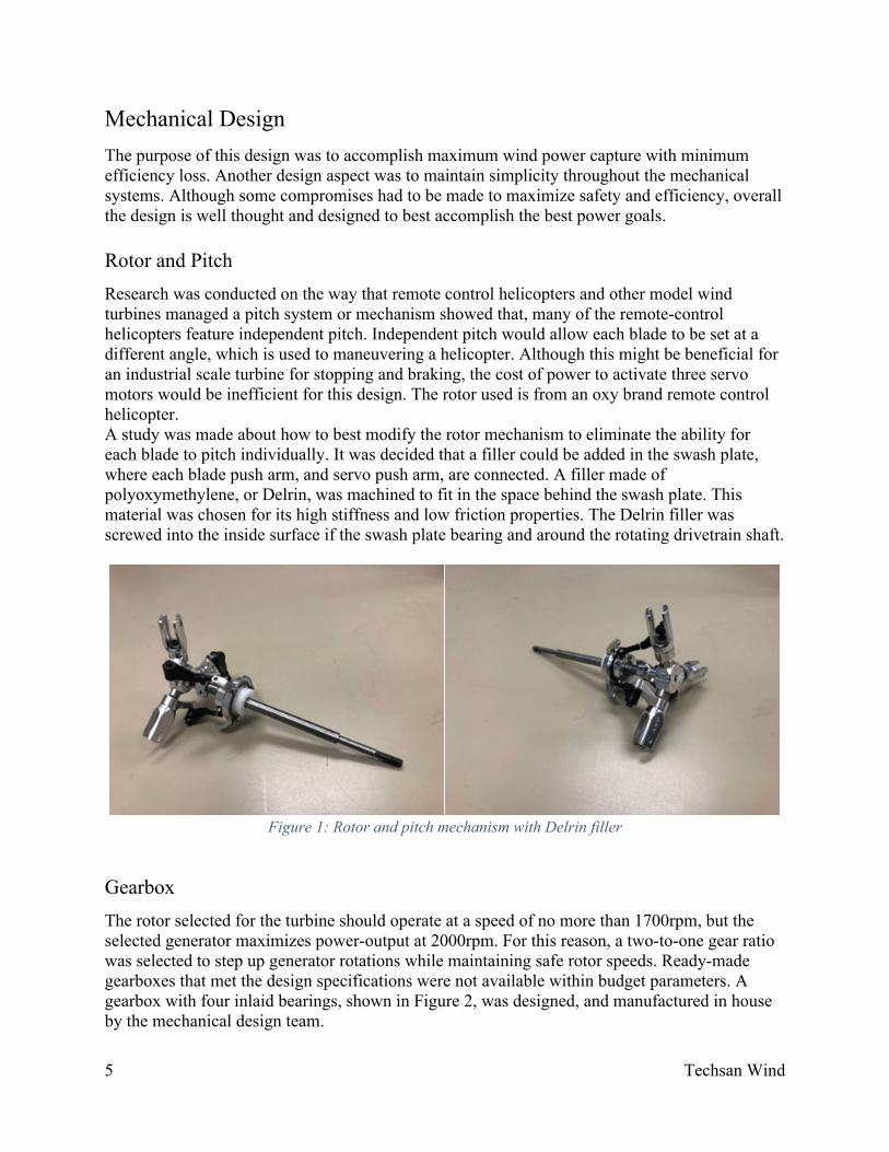
Rotor and Pitch Research was conducted on the way that remote control helicopters and other model wind turbines managed a pitch system or mechanism showed that, many of the remote-control helicopters feature independent pitch. Independent pitch would allow each blade to be set at a different angle, which is used to maneuvering a helicopter. Although this might be beneficial for an industrial scale turbine for stopping and braking, the cost of power to activate three servo motors would be inefficient for this design. The rotor used is from an oxy brand remote control helicopter. A study was made about how to best modify the rotor mechanism to eliminate the ability for each blade to pitch individually. It was decided that a filler could be added in the swash plate, where each blade push arm, and servo push arm, are connected. A filler made of polyoxymethylene, or Delrin, was machined to fit in the space behind the swash plate. This material was chosen for its high stiffness and low friction properties. The Delrin filler was screwed into the inside surface if the swash plate bearing and around the rotating drivetrain shaft.
Figure 1: Rotor and pitch mechanism with Delrin filler
Gearbox The rotor selected for the turbine should operate at a speed of no more than 1700rpm, but the selected generator maximizes power-output at 2000rpm. For this reason, a two-to-one gear ratio was selected to step up generator rotations while maintaining safe rotor speeds. Ready-made gearboxes that met the design specifications were not available within budget parameters. A gearbox with four inlaid bearings, shown in Figure 2, was designed, and manufactured in house by the mechanical design team.
Techsan Wind 5

Figure 2: Gearbox
The gears selected are made from stainless-steel. The input gear has 36 teeth and the output gear has 18 teeth. The gears mesh inside the gear box, where the rotor and generator shafts pass through the bearings on either side of the box and the gears. The shafts and gears are prevented from shifting because snap-rings around the shafts within the gearbox prevent the forwards or backwards shifting of the shaft by staying pressed against the rotational ring of the bearings, allowing only rotational motion. On the bottom of the gearbox screw holes were drilled in so the gearbox can be attached to the base plate. It is important that the gearbox was design well so that the gears make contact in the correct surfaces. Securing the gearbox ensures that the box does not shift, causing severe stress on the gear and shafts.
Drivetrain To achieve optimum power production, according to the generator datasheet, the generator needs to rotate at 2000 rpm, but the rotor pieces selected are not designed to endure sustains speeds over 1700 rpm. As a result, the wind turbine could not operate using a direct drive system and a gearbox was added in order to achieve the 2000 rpm the generator would need without causing damage or failure in the rotor. The front half of the drive train is the low speed shaft and consists of the rotor and pitch mechanism. The shaft from the rotor leads into the input of the gearbox and a stainless-steel gear with 36 teeth. A high-speed shaft connects a gear with 18 teeth in the gearbox and the generator. These gears were chosen to build a gear box with a 2:1 ratio. The ratio allows for the rotor to operate at safe speeds and meet the optimal power production at the same time. Minimizing the ratio was necessary to reduce to prevent unnecessarily increasing the starting torque of the rotor, thus increasing the minimum wind speed of the wind turbine.
Techsan Wind 6

In order to ensure that the shaft from the rotor to the input of the gearbox were supported and held stable, supports and bearings are added. The two shafts were made of steel to ensure that the shafts would not fail while under the stresses caused from the rotation and weight of the rotor and generator. The rotor and generator stands are also made of steel because of the rigid properties, which help to maintain efficient connection between the gears and minimize flex and stress in the shaft and gear box. This system was tested using a dynamometer, in which the rotor shaft or generator shaft is connected to a control motor to regulate the rpms of the drivetrain. During this test, stress and misalignment issues can be located in the rotor shaft and blades. Later, this system can be used to isolate and troubleshoot power production and power quality problems.
Figure 3: Dynamometer and controls for rotor stress test
Yaw Mechanics For this wind turbine, an active yaw system was chosen to prevent the use of large fin and to make it easier to balance the weight of the nacelle and the dynamic movements on the tower. The parts include a tubular tower, with the mounting flange at the base that connects to the competition stand. A rotary encoder will be used at the top of the nacelle to simulate a wind vain, which will send a signal to a stepper motor to power the yaw. The tower has an outer diameter of 2” and the stepper motor shaft has a diameter of ¼”. This drastic difference in diameter made it very difficult to match a tooth pitch on a gear that would fit on the stepper motor and the tower. The inner diameter of the tower cannot be compromised because the space is needed for power and control wires to travel from the nacelle to the control box and power reader.
Techsan Wind 7

Figure 4: New yaw design preliminary sketch
In the next design, a lip is added to the upper section of the tower for a thrust bearing and shield to sit. The bed plate would be placed around the tower and supported by the bearing shield. A thrust bearing is only effective when a pre-tension load is applied, therefore a needle bearing is placed on top of the bedplate and custom threaded nut creates the tension. Under the thrust bearing and lip will be a sprocket or HTD gear. Again, the issue of mating the pitch of sprocket or HTD gear of the pipe diameter and the stepper motor diameter poses a challenge. It is possible to find a gear or sprocket that fits on the stepper motor and manufacture a large piece, with smaller teeth that match the other gear. Though testing and adjustments may be necessary, this design is superior because will provide better support.
Aerodynamics A three blade, horizontal axis design was selected to optimize wind power capture. Because the drivetrain will utilize a gear ratio rather than direct drive, the turbine blades are designed to maximize lift, to overcome the initial torque in the gears and generator. To accomplish this, the blades were designed with a wide base, and rather than including a stem where the blades attach to the rotor arms, the blades are cut with a slot that allows the rotor arms to slide over and sit flush with the blade surface. This design was decided on because of the size restriction on the total rotor diameter. The rotor arms take up length that is needed to maximize blade area. By including the rotor arms in the blade surface, more surface was devoted to generating lift, allowing the blades to overcome initial torque so the turbine can begin generating power in lower wind speeds. Including the rotor as part of the blade surface will address the stress concentration issue at the blade rood as well. High wind speeds increase the force of the blade surface and create a large moment at the base of the blade. Increasing the cross-sectional area at the root connection of the blade, decreases the pressure caused by the moment, therefore reducing the risk of failure.
Techsan Wind 8

Figure 5: Turbine blades made of 3D printed plastic
The gear ratio was selected based on tip speed ratio (TSR) calculation, which is a magnification of the wind velocity to the linear velocity of the blade tip. Therefore, a higher TSR can mean more wind capture. Using the desired rotation of the generator, and the stress capacity of the rotor, the 2:1 ratio was selected. This ratio allowed the rotor to operate at a safe speed and are cost-effective standard gears. This ratio was also chosen to minimize the amount of added starting torque for the lift force to overcome.
Electrical Overview To achieve better wind power capture, this design features active pitch and yaw control systems. The pitch will regulate the rotational speed of the rotor and blades to control the power curve and maintain steady power production. Active yaw will assure that the nacelle is always oriented in the direction of the wind flow and reduce the pulsing effect of stabilization. A Basys 3 board was selected as the control because it has a processing speed of 450MHz. This speed is a due to the processing system in the board is a series of complex gates, rather than a CPU type processor.
Pitch Control The pitch is controlled by the amount of current flowing through the system. This is achieved by using a Basys 3 board. A current sensor sends a voltage to the Basys board, a driver for the servo and the servo itself. Since the output voltage from the current sensor is based on the current flowing through the system it gives an approximation about the required pitch of the blades to control rotation and power output. Because the current and wind speed are correlated, the pitch will change variably with the current. As a result, if the current is too high, the blades will pitch back to reduce rotation, and the opposite is true. The servo controlled by the Basys board has code that is set up with case statements. Depending on the value of the voltage being sent from the current sensor, it tells the Basys board which case
Techsan Wind 9

to activate. Since the rules of the competition ask for power regulation, the pitching will be determined by the current input to the current sensor. The servo will keep the current at a set level with the pitch which will be dependent after testing.
Yaw Control The stepper motor being used is a Nema 17 short body stepper motor. The reason this was chosen was due to its holding torque and small design. The holding torque of the motor is 16 Ncm, more than enough to turn and hold the nacelle of the turbine while following the wind. The size of the motor is 42 x 42 x 20 millimeters. The Nema 17 is a bipolar stepper motor that turns by controlling four magnetic inducting coils that pull a neodymium magnet in the direction commanded by the coils magnetic flux. This is done by stepping through the coils one by one in the order of the wire’s configuration. For the Nema 17’s full clockwise rotation of the motor, the steps would need to send a current through the wire labeled A+ first then to wire A-, then wire B+ followed by B-. Depending on the turning direction desired, the order of the coils being pulsed could be reversed. If you request the motor hold its position, you will constantly send a current through two of the wires that are located next to each other.
Figure 6: Schematic for Yaw System
The rotary encoder being used is an optical incremental encoder with 600 points per rotation. This will have a wind vane attached to the shaft of the encoder to control the signals being sent out to the circuit board which will interpret how to pulse the poles of the stepper motor. The design is intended for the stepper motor to follow the movement of the rotary encoder, so the nacelle is constantly facing the direction of the wind. There are only two signals that are sent out of the encoder, so for the encoder to control the stepper motors four coils the signals had to be
Techsan Wind 10

duplicated and inverted to create oscillating pulses that are sent through the driver to be amplified and then sent to the motor.
Power Quality and Control The generators power will be fed into a rectifier to convert the alternating current into a direct current. From the rectifier for DC voltage smoothing there is a 1000uF capacitor with a storage capacity of 1.8 joules to level the power output. There is a manual switch to control the connection of the battery to the generator and the electronics, after the generator charges the battery the relay switch will allow for the battery to power the control system if the generator stops producing power. For controlling the max voltage there is a 48-volt relay that will cause the rotor to brake if the system reaches or exceeds 48 volts by shorting the rectifier terminals. If the 48-volt relay is activated there is another relay that will be activated and cut the power to the load as to prevent the power from reaching the load even further. The emergency stop switch is connected to a 5-volt relay that allows power to flow through the system until the switch is pressed which then allows the system to short across the rectifier, stopping the rotor. If the rectifier is shorted in one of these events, the battery will allow for the electronics to function normally given that it has been charged. The circuit board for the yaw system will be connected to the main power line so power can be pulled to power the stepper motor, rotary encoder, and the circuit board. The circuit board for the yaw will have two DC to DC converters that will pull and regulate the voltage to 5 volts and 24 volts. The 5-volt converter will feed an estimated total of .25 amperes into the rotary encoder, and the inverter. There is a 24-volt converter that will be passing around 2 amperes through the driver to amplify the rotary encoder signals and power the stepper motor. The other electronics such as the Basys 3 board, current sensor, servo, and relays will be pulling from three 5-volt regulators that will be connected to the main power line. To keep the power at a level and optimal wattage, the current sensor will take in data from the main power line and pass it to the Basys 3 board to inform the servo motors how to pitch the blades. Since the generator maintains a constant voltage the current will be controlled by the speed of the rotation of the blades. The optimal current will be around 12 amperes with the total system consuming around 4 amperes allowing us to output close to 400 watts.
Techsan Wind 11

Results The turbine cannot begin using power from its battery until power has been generated, so the blades will need to be set at an optimal angle before starting. Once more power is generated, the pitch and yaw will be continuously adjusting to maximize and control power output. The Basys 3 board and programming would have monitored these conditions and made adjustments as necessary. The majority of the turbine was manufactured from either steel or aluminum. Parts that are not as susceptible to fatigue were manufactured out of aluminum. The turbine blades would have been machined from a block of aluminum as well, to allow for a smooth surface and better aerodynamics, but tests were first conducted with 3D prints of the design so that adjustments could be made before the design was finalized. A rotor and blade test were conducted using a dynamometer, in which we ran our rotor at 1700rpms for approximately 20 minutes to ensure it could function at this speed without causing damage to the blades or the rotor itself. The test ran well, and no problems or fractures were detected. This test was necessary because though the rotor was approved to operate at this speed, the blades it would have initially been carrying were small, thin, and light RC-helicopter blades. The turbine blades designed are much larger and heavier. The blades were designed in QBlade, a turbine blade designing software. In this opensource software, different industrial turbine blade schematics are available for modification and testing. After running tests on many different blade designs, it was determined that to generate enough lift to overcome initial torque the blade that worked the best had a wide cross-section with a flat blade face and no rotation in the blade. The blades have a length from tip to base of 7.5in, after entering this information into QBlade with the selected cross-section, rate of tapering and other features the blades were optimized to the shape pictured in figure 5.
Discussion The model turbine was on track to begin testing at the end of March, however when the project was moved to a digital format, there was no opportunity to construct or run tests on of the assembled parts. There were a few changes made from the original concept to manufactured product through the course of this project. Initially, the drivetrain was designed with direct drive from the rotor to the generator. It was discovered that the generator is optimized at higher rpm’s than the rotor is approved for, therefore a 2:1 gear ratio was installed to step up the revolutions of the generator shaft from the rotor. This allows the generator to reach its optimal operating speed while maintaining safety in rotor rotations. It was necessary to make the turbine heavier than initially anticipated to improve its operation in higher wind speeds. To maintain strength and durability, the turbine is constructed primarily from steel and aluminum. The increased strength of the components will allow the turbine to produce more power than it could with less durable materials by sustaining power production in harsh conditions. Without physical tests of the final product, it is difficult to say if anything in this turbine could have been improved. The theoretical results of the stress analysis, the dynamometer testing, and the lift and torque calculations conducted to design our final product suggest that the final concept will function well. But there are likely issues that would have been realized and potential adjustments made to the design as the physical construction and testing progressed.
Techsan Wind 12

Conclusion The final design is a miniature wind turbine designed to optimize power with a step-up gearbox, so the rotor does not have to spin as fast to achieve the same power output. Active yaw was chosen so that a fin would not have to be used on the back of the turbine. This is possible by the simplistic design of the yaw controls. Reducing the number of servo motor required for pitch the blades was key in reducing the power and control needed to regulate the pitch system. A direct drive system would be ideal; however, it was not possible to achieve with the materials selected. Further testing would have shown if this improved or hindered the overall design.
Techsan Wind 13

References Budynas, Richard G. (2011) Shigley’s Mechanical Engineering Design. Ed. 9. New York, NY.
McGraw Hill Hanson, Martin O. L. (2008). Aerodynamics of Wind Turbines. Ed. 8. Sterling, VA. Earthscan Hibbeler, R. C., & Yap, K. B. (2018). Mechanics of materials. Ed. 10. Harlow: Pearson
Education. US Department of Energy. (2019). Collegiate Wind Competition 2020
Acknowledgements Dr. Burak Aksak – Mechanical Engineering Dr. Scott Clark – Computer and Electrical Engineering Chase George – Machinist Prof. George Gray – Mechanical Engineering Dr. Victor Maldonado – Mechanical Engineering Roy Mullins – Engineer David Myers – Machinist Dr. Arquimedes Ruiz-Columbie – Wind Energy Prof. Matt Saldana – Wind Energy Dr. Andy Swift – Wind Energy Brandon & Clark, Inc – Lubbock, Texas
Techsan Wind 14

Appendix A: Parts Drawings
Base plate holding all components for the wind turbine.
Stand was attached to the base plate to hold up the generator.
Techsan Wind 15

Gear box used to house gears with 2 to 1 gear ratio.
Used to stabilize the shaft attached to the rotor with inlayed bearing.
Techsan Wind 16

Nut holding the tower to the base plate.
This is the final assembly of the project
Techsan Wind 17

Appendix B: FEA Stress analysis
Stress analysis of 100lbf on all holes. Part made of Aluminum 6061
Stress analysis of 100lbf on center hole. Part made of Aluminum 6061
Stress analysis of 100lbf on lower hole. Part made of Aluminum 6061
Techsan Wind 18

Stress analysis of 100lbf on center hole. Part made of Aluminum 6061
Stress analysis of 100lbf on center hole. Part made of Aluminum 6061
Techsan Wind 19