Summit24e2 Installation and User’s Guide...Summit24e2 Installation and User’s Guide 1-1 1...
142
Extreme Networks, Inc. 3585 Monroe Street Santa Clara, California 95051 1 (408) 579-2800 http://www.extremenetworks.com Summit24e2 Installation and User’s Guide Published: Octoberl 2001
Transcript of Summit24e2 Installation and User’s Guide...Summit24e2 Installation and User’s Guide 1-1 1...

Extreme Networks, Inc.
3585 Monroe Street
Santa Clara, California 95051
1 (408) 579-2800
http://www.extremenetworks.com
Summit24e2 Installationand User’s Guide
Published: Octoberl 2001

I
©2000 Extreme Networks, Inc. All rights reserved. Extreme Networks and BlackDiamond areregistered trademarks of Extreme Networks, Inc. in the United States and certain other jurisdictions.ExtremeWare, ExtremeWare Vista, ExtremeWorks, ExtremeAssist, ExtremeAssist1, ExtremeAssist2,PartnerAssist, Extreme Standby Router Protocol, ESRP, SmartTraps, Alpine, Summit, Summit1,Summit4, Summit4/FX, Summit7i, Summit24, Summit48, Summit Virtual Chassis, SummitLink,SummitGbX, SummitRPS and the Extreme Networks logo are trademarks of Extreme Networks, Inc.,which may be registered or pending registration in certain jurisdictions. The Extreme Turbodrive logois a service mark of Extreme Networks, which may be registered or pending registration in certainjurisdictions. Specifications are subject to change without notice.
NetWare and Novell are registered trademarks of Novell, Inc. Merit is a registered trademark of MeritNetwork, Inc. Solaris is a trademark of Sun Microsystems, Inc. F5, BIG/ip, and 3DNS are registeredtrademarks of F5 Networks, Inc. see/IT is a trademark of F5 Networks, Inc.
“Data Fellows”, the triangle symbol, and Data Fellows product names andsymbols/logos are trademarks of Data Fellows.
F-Secure SSH is a registered trademark of Data Fellows.
All other registered trademarks, trademarks and service marks are property of their respective owners.

Table of Contents i
Table of Contents
1 Introduction - Summit24e2 Fast Ethernet Switch
Features 1Ports 1Performance Features 2Management Features 3
Switching Technology 4Fast Ethernet Technology 5Gigabit Ethernet Technology 5
2 Unpacking and Setup
Unpacking 7
Installation 8Desktop or Shelf Installation 8Rack Installation 8
Power On 10Power Failure 10
3 Identifying External Components
Front Panel 11
Rear Panel 12
Side Panels 13
Gigabit Ethernet Two-Port Module 13

ii Table of Contents
GBIC Two-Port Module 14
LED Indicators 15
4 Connecting the Switch
Switch to End Node 17
Switch to Hub or Switch 18
5 Switch Management Concepts
Local Console Management 21Diagnostic (Console) Port (RS-232 DTE) 22
IP Addresses and SNMP Community Names 24
Traps 25
MIBs 27
SNMP 28Authentication 28
Packet Forwarding 29MAC Address Aging Time 29
Packet Filtering 29
Spanning Tree Protocol 30STP Operation Levels 31
Switch Level STP 31Port Level STP 32Bridge Protocol Data Units 32Creating a Stable STP Topology 33STP Port States 33Default Spanning-Tree Configuration 35User-Changeable STP Parameters 36Illustration of STP 37
Port Aggregation 38
VLANs 39Sharing Resources Across VLANs 40Port-based VLANs 41
IEEE 802.1Q VLANs 41802.1Q Packet Forwarding Decisions 42

Table of Contents iii
802.1Q VLAN Tags 43Port VLAN ID 45Tagging and Untagging Packets 46Ingress Filtering 47Configuring VLANs 47Broadcast Storms 48Segmenting Broadcast Domains 48Eliminating Broadcast Storms 48Multicasting 49Multicast Groups 49Multicast Addressing 49Internet Group Management Protocol (IGMP) 49
6 Using the Console Interface
Console Screen Heirachary 51
Setting Up a Console 54Connecting to the switch Using Telnet 54Console Usage Conventions 54First Time Connecting To The switch 55
User Accounts Management 57Root, User+ and Normal User Privileges 59
Saving Changes 59
Logging On As a Registered User 61
Setup User Accounts 61Update/Delete User Accounts 62
Setting Up the switch 63
Basic Setup 64Switch Information 65Basic Network Setup 66Configuring the Serial Port 68Configure Ports 69
Configure the Gigabit Ethernet Ports 71
Network Management Setup 72SNMP Configuration 73Setting Trap Receivers 73Management Station IP Address Setup 75Switch Utilities 75

iv Table of Contents
Upgrade Firmware from a TFTP Server 76Download a Configuration File From a TFTP Server 78Save Configuration File to a TFTP Server 79Save switch History to TFTP Server 80Ping Test 81
Network Monitoring 82Link Utilization Averages 83Port Error Statistics 84Port Packet Analysis 86MAC Address Forwarding Table 87Browse the ARP Table 88Browse the Routing Table 89Browse Router Port 90IGMP Snooping Status 91Switch History Log 92
Reboot 93
Advanced Setup 94Configuring the Spanning Tree Protocol 95
STP Parameter Settings 95Port Spanning Tree Settings 97
Forwarding 99MAC Address Aging Time 99Broadcast/Multicast Storm Control 101Unicast MAC Address Forwarding 102Multicast MAC Address Forwarding 104Static IP Forwarding 105
Priority 106Priority Queue Configuration 106MAC Address Priority 109
Port Mirroring 111IGMP Configuration 113
IGMP Snooping Settings 114Static Router Port Settings 115
VLANs 117Configure VLANs 117Configuring Port-Based VLANs 120
Link Aggregation 122
A Appendix A - Technical Specfications

Table of Contents v
B Appendix B - Runtime Switching Software Defaults

vi Table of Contents

Summit24e2 Installation and User’s Guide 1-1
1 Summit24e2 Overview
Features
The Summit24e2 Switch was designed for easy installation and high performance in anenvironment where traffic on the network and the number of users increasecontinuously.
The Summit24e2 is a 24 10/100 Mbps port Ethernet switch with two Gigabit Ethernetports. The Summit24e2 supports auto-negotiation between 10 Mbps and 100 Mbps atfull or half-duplex operation on all 24 ports simultaneously.
Switch features include the following:
Ports• 24 high performance, auto-negotiating ports all operating at 10/100 Mbps for
connecting to end stations, servers and hubs.
• All ports can auto-negotiate between 10 Mbps/100 Mbps, half-duplex or full duplexand flow control for half-duplex ports.
• RS-232 DTE Diagnostic port (console port) for setting up and managing the switchvia a connection to a console terminal or PC using a terminal emulation program.
• Two 1000Base-T or two GBIC Ethernet ports.

1-2 Summit24e2 Installation and User’s Guide
Summit24e2 Overview
Performance Features• 8.8 Gbps switching fabric capacity
• Store and forward switching scheme.
• Full and half-duplex for both 10 Mbps and 100 Mbps connections. The GigabitEthernet ports operate at full-duplex only. Full-duplex allows the port tosimultaneously transmit and receive data, and requires full-duplex end stations andswitches. Connections to hubs must take place at half-duplex.
• Supports IEEE 802.3x flow control for full-duplex mode ports.
• Supports back-pressure flow control for half-duplex mode ports.
• Auto-polarity detection and correction of incorrect polarity on the transmit andreceive twisted-pair at each port.
• IEEE 802.3z compliant for all Gigabit ports.
• IEEE 802.3x compliant Flow Control support for all Gigabit ports.
• IEEE 802.3ab compliant for 1000BASE-TX (Copper) Gigabit ports.
• Data forwarding rate 14,880 pps per port at 100% of wire-speed for 10Mbps speed.
• Data forwarding rate 148,800 pps per port at 100% of wire-speed for 100Mbps speed.
• Data filtering rate eliminates all error packets, runts, etc. at 14,880 pps per port at100% of wire-speed for 10 Mbps speed.
• Data filtering rate eliminates all error packets, runts, etc. at 148,800 pps per port at100% of wire-speed for 100 Mbps speed.
• 8K active MAC address entry table per device with automatic learning and aging (10to 1,000,000 seconds).
• 16 MB packet buffer per device.
• Broadcast and Multicast storm filtering.
• Supports Port Mirroring.
• Supports Port Trunking – up to six trunk groups (each consisting of up to eightports) can be set up.
• 802.1D Spanning Tree support.
• 802.1Q Tagged VLAN support – up to 63 User-defined VLANs per device (oneVLAN is reserved for internal use).
• 802.1p Priority support with 4 priority queues.
• IGMP Snooping support.

Summit24e2 Installation and User’s Guide 1-3
Switching Technology
Management Features• RS-232 console port for out-of-band network management via a console terminal or
PC.
• Spanning Tree Algorithm Protocol for creation of alternative backup paths andprevention of network loops.
• SNMP v.1 agent.
• Fully configurable either in-band or out-of-band control via SNMP based software.
• Flash memory for software upgrades. This can be done in-band via TFTP orout-of-band via the console.
• Built-in SNMP management:
— Bridge MIB (RFC 1493).
— MIB-II (RFC 1213).
— Mini-RMON MIB (RFC 1757) - 4 groups.
— CIDR MIB (RFC 2096), except IP Forwarding Table.
— 802.1p MIB (RFC 2674).
— RIP MIB v2 (RFC 1724).
• Supports Web-based management.
• TFTP support.
• BOOTP support.
• BOOTP relay agent.
• DCHP client support.
• DCHP relay agent.
• DNS relay agent.
• Password enabled.
Switching Technology
Another key development pushing the limits of Ethernet technology is in the field ofswitching technology. A switch bridges Ethernet packets at the MAC address level ofthe Ethernet protocol, transmitting among connected Ethernet or fast Ethernet LANsegments.

1-4 Summit24e2 Installation and User’s Guide
Summit24e2 Overview
Switching is a cost-effective way of increasing the total network capacity available tousers on a local area network. A switch increases capacity and decreases networkloading by making it possible for a local area network to be divided into differentsegments which don’t compete with each other for network transmission capacity, givinga decreased load on each.
The switch acts as a high-speed selective bridge between the individual segments.Traffic that needs to go from one segment to another (from one port to another) isautomatically forwarded by the switch, without interfering with any other segments(ports). This allows the total network capacity to be multiplied, while still maintainingthe same network cabling and adapter cards.
For Fast Ethernet or Gigabit Ethernet networks, a switch is an effective way ofeliminating problems of chaining hubs beyond the “two-repeater limit.” For example, aswitch can be used to split parts of the network into different collision domains, makingit possible to expand your Fast Ethernet network beyond the 205 meters networkdiameter limit for 100BASE TX networks. Switches supporting both traditional 10MbpsEthernet and 100Mbps Fast Ethernet are also ideal for bridging between existing10Mbps networks and new 100Mbps networks.
Switching LAN technology is a marked improvement over the previous generation ofnetwork bridges, which were characterized by higher latencies. Routers have also beenused to segment local area networks, but the cost of a router and the setup andmaintenance required can make routers impractical in some situations. Today’s switchesare an ideal solution for many kinds of local area congestion problems.
Fast Ethernet Technology
100 Mbps Fast Ethernet (or 100BASE-T) is a standard specified by the IEEE 802.3 LANcommittee. It is an extension of the 10Mbps Ethernet standard with the ability totransmit and receive data at 100Mbps, while maintaining the Carrier Sense MultipleAccess with Collision Detection (CSMA/CD) Ethernet protocol.
Gigabit Ethernet Technology
Gigabit Ethernet is an extension of IEEE 802.3 Ethernet utilizing the same packetstructure, format, and support for CSMA/CD protocol, full duplex, flow control, andmanagement objects, but with a tenfold increase in theoretical throughput over100Mbps Fast Ethernet and a one hundred-fold increase over 10Mbps Ethernet. Since itis compatible with all 10Mbps and 100Mbps Ethernet environments, Gigabit Ethernet

Summit24e2 Installation and User’s Guide 1-5
Switching Technology
provides a straightforward upgrade without wasting a company's existing investmentin hardware, software, and trained personnel.
Gigabit Ethernet enables fast optical fiber connections and Unshielded Twisted Pairconnections to support video conferencing, complex imaging, and similar data-intensiveapplications. Likewise, since data transfers occur 10 times faster than Fast Ethernet,servers outfitted with Gigabit Ethernet NIC's are able to perform 10 times the numberof operations in the same amount of time.

1-6 Summit24e2 Installation and User’s Guide
Summit24e2 Overview

Summit24e2 Installation and User’s Guide 2-1
2 Unpacking and Setup
This chapter provides unpacking and set-up information for the switch.
• Unpacking
• Installation
• Power On
Unpacking
Open the shipping carton of the switch and carefully unpack its contents. The cartonshould contain the following items:
• One Summit24e2 24-port Ethernet Switch
• Mounting kit: 2 mounting brackets and screws
• Four rubber feet with adhesive backing
• One AC power cord
• One Extreme Networks Documentation CD
• User Registration
• License Agreement
If any item is found missing or damaged, please contact your local Extreme Networksreseller for replacement.

2-2 Summit24e2 Installation and User’s Guide
Unpacking and Setup
Installation
Use the following guidelines when choosing a place to install the Switch:
• The surface must support at least 3 kg.
• The power outlet should be within 1.82 meters (6 feet) of the device.
• Visually inspect the power cord and see that it is secured to the AC power connector.
• Make sure that there is proper heat dissipation from and adequate ventilationaround the switch. Do not place heavy objects on the switch.
Desktop or Shelf Installation
When installing the Switch on a desktop or shelf, the rubber feet included with thedevice should first be attached. Attach these cushioning feet on the bottom at eachcorner of the device, as shown in Figure 2-1. Allow adequate space for ventilationbetween the device and the objects around it.
Summit24e2
Figure 2-1: Installing Rubber Feet for Desktop Installation
Rack Installation
The Summit24e2 can be mounted in an EIA standard-sized, 19-inch rack, which can beplaced in a wiring closet with other equipment. To install:

Summit24e2 Installation and User’s Guide 2-3
Installation
Attach the mounting brackets on the switch’s side panels (one on each side), and securethem with the screws provided, as shown in Figure 2-2.
Figure 2-2: Attaching the Mounting Brackets to the Switch
Use the screws provided with the equipment rack to mount the switch on the rack asshown in Figure 2-3.
Figure 2-3: Installing the Switch on an Equipment Rack

2-4 Summit24e2 Installation and User’s Guide
Unpacking and Setup
Power On
The Summit24e2 switch can be used with AC power supply 100 - 240 VAC, 50 - 60 Hz.The switch’s power supply will adjust to the local power source automatically and maybe turned on without having any or all LAN segment cables connected.
After the power switch is turned on, the LED indicators should respond as follows:
• Power and Status LED indicators will momentarily blink. This blinking of the LEDindicators represents a reset of the system.
• The Status LED indicator will blink while the switch loads onboard software andperforms a self-test. After approximately 20 seconds, the LED will light again toindicate the switch is in a ready state.
• The console LED indicator will remain ON (glowing green) if there is a connection atthe RS-232 port; otherwise this LED indicator is OFF.
• The 100M LED indicator may remain ON (glowing green) or OFF depending on thetransmission speed.
Power Failure
As a precaution, in the event of a power failure, unplug the switch. When the powersupply is restored, plug the switch back in.

Summit24e2 Installation and User’s Guide 3-1
3 Identifying External Components
This chapter describes the front panel, rear panel, and LED indicators of theSummit24e2.
• Front Panel
• Rear Panel
• Side Panels
• LED Indicators
Front Panel
The front panel of the Switch consists of:
• LED indicators
• An RS-232 communication port
• Two Gigabit Ethernet ports, either GBIC or 1000Base-T
• Twenty-four 10/100 Mbps Ethernet/Fast Ethernet ports

3-2 Summit24e2 Installation and User’s Guide
Identifying External Components
Figure 3-1: Front Panel View of the Switch
• Comprehensive LED indicators display the status of the switch and the network. Adescription of these LED indicators follows (see “LED Indicators” on page -5).
• An RS-232 DTE console port for setting up and managing the switch via aconnection to a console terminal or PC using a terminal emulation program.
• 24 high-performance Ethernet ports all of which operate at 10/100 Mbps forconnections to end stations, servers and hubs. All ports can auto-negotiate between10 Mbps or 100 Mbps, full- or half-duplex, and flow control.
Rear Panel
The following displays the rear panel of the switch.
Figure 3-2: Rear Panel View of the Switch
• The AC power connector is a standard three-pronged connector that supports thepower cord. Plug in the female connector of the provided power cord into thissocket, and the male side of the cord into a power outlet. Supported input voltagesrange from 100 ~ 240 VAC at 50 ~ 60 Hz.

Summit24e2 Installation and User’s Guide 3-3
Side Panels
Side Panels
The right side panel of the Switch contains two system fans (see the top part of thediagram below). The left side panel contains heat vents.
Figure 3-3: Side Panel Views of the Switch
The system fans are used to dissipate heat. The sides of the system also provide heatvents to serve the same purpose. Do not block these openings, and leave at least 6inches of space at the rear and sides of the switch for proper ventilation. Remember thatwithout proper heat dissipation and air circulation, system components might overheat,which could lead to system failure.
Gigabit Ethernet Ports
The Summit24e2 24-port Ethernet Switch includes two Gigabit Ethernet ports. TheGigabit Ethernet ports support either fiber optic cable (via a GBIC interface) or1000BASE-TX (using Cat. 5 copper cable).

3-4 Summit24e2 Installation and User’s Guide
Identifying External Components
GBIC Slots
Figure 3-4: GBIC Two-Port Module
• Connects to GBIC devices at full duplex only.
• Allows multi-mode fiber optic connections of up to 550 m (SX and LX) andsingle-mode fiber optic connections of up to 5 km (LX only). GBIC modules areavailable in -SX and -LX fiber optic media.
Table 3-1: Fiber Cable Lengths for GBIC
62.5µm 62.5µm 50µm 50µm
ModalBandwidth
160MHz*km 200 400 500
OperatingDistance
220 meters 275 500 550
ChannelInsertion Loss
2.33dB 2.53 3.25 3.43

Summit24e2 Installation and User’s Guide 3-5
LED Indicators
1000BASE-TX Ports
Figure 3-5: 1000BASE-TX ports
• Allows connection to 1000BASE-TX devices using Cat. 5e copper cable.
• 100/1000 Mbps Auto-Negotiation.
• 1000 Mbps connection is full-duplex only.
• Automatic MDI/MDIX uplink connection allowing the use of either astraight-through or a cross-over cable.
LED Indicators
The Switch’s LED indicators include:
• Power
• Status
• Link/Act
The following shows the LED indicators and provides an explanation of each indicator.
Figure 3-6: The Switch LED Indicators

3-6 Summit24e2 Installation and User’s Guide
Identifying External Components
Power — this indicator on the front panel should be lit during the Power-On Self Test(POST). It will light green approximately 2 seconds after the switch is powered on toindicate the ready state of the device.
Status — this indicator is lit green when the switch is able to be managed viaout-of-band/local console management through the RS-232 console port using astraight-through serial cable.
Link/Act — these indicators are located to the left and right of each port. They are litwhen there is a secure connection (or link) to a device at any of the ports. The LEDsblink whenever there is reception or transmission (i.e. Activity--Act) of data occurring ata port.

Summit24e2 Installation and User’s Guide 4-1
4 Connecting the Switch
This chapter describes how to connect the Summit24e2 to your Fast Ethernet network.
• Switch to End Node
• Switch to Hub or Switch
Switch to End Node
End nodes include PCs outfitted with a 10, 100, 10/100, 1000 or 100/1000 Mbps RJ-45Ethernet/Fast Ethernet Network Interface Card (NIC) and most routers. Summit24e2switches supplied with GBIC Gigabit Ethernet ports can be connected to otherfiber-optic switch ports using the SC-type connector.
An end node can be connected to the Switch via a two-pair Category 3, 4, 5 UTP/STPstraight cable (be sure to use Category 5e UTP or STP cabling for 100 and 1000 MbpsFast Ethernet or Gigabit Ethernet connections). End nodes can be connected to any ofthe twenty-four 10/100 Mbps ports (1 - 24) of the Summit24e2, or to either of the twoGigabit ports on the front panel.

4-2 Summit24e2 Installation and User’s Guide
Connecting the Switch
Figure 4-1: Switch Connected to an End Node
The LED indicators for the port that the end node is connected to are lit according tothe capabilities of the NIC. If LED indicators are not illuminated after making a properconnection, check the PC’s LAN card, the cable, switch conditions, and connections.
The following LED indicator states are possible for an end node to switch connection:
• The 100M LED indicator glows green for a 100 Mbps and stays OFF for 10 Mbps.
• The Link/Act LED indicator glows green upon hooking up a PC that is powered onand flashes to indicate that a working link has been established (there is activity —packets being received or transmitted — across the link).
Switch to Hub or Switch
These connections can be accomplished in a number of ways. The most importantconsideration is that when using a normal, straight-through cable, the connectionshould be made between a normal crossed port (Port 2, 3, etc.) and an Uplink (MDI-II)port. If you are using a crossover cable, the connection must be made from Uplink toUplink (port 1 on the Summit24e2), or from a crossed port to another crossed port.

Summit24e2 Installation and User’s Guide 4-3
Switch to Hub or Switch
Figure 4-2: Switch Connected to Another Switch
• A 10BASE-T hub or switch can be connected to the Switch via a two-pair Category 3,4 or 5 UTP/STP straight cable.
• A 100BASE-TX hub or switch can be connected to the Switch via a two-pairCategory 5e UTP/STP straight cable.
If the other switch or hub contains an unused Uplink port, we suggest connecting theother device's Uplink (MDI-II) port to any of the switch's (MDI-X) ports (2 - 23, or oneof the Gigabit module ports) using a normal straight-through cable — for the1000BASE-TX module or a pair of fiber optic cables for the GBIC module, as shown inFigure 4-3, below.
• A 1000BASE-TX switch can be connected to the switch via a two-pair Category 5eUTP/STP straight cable.
• A GBIC switch can be connected to the switch via a pair of fiber optic cables, withthe Tx port on one switch connected to the Rx port on the second switch, andvice-versa.
• GBIC connections can be made in full-duplex, only.
• GBIC allows multi-mode fiber optic connections of up to 550 m.

4-4 Summit24e2 Installation and User’s Guide
Connecting the Switch
Figure 4-3: GBIC Port Connected to Another Switch’s GBIC Port

Summit24e2 Installation and User’s Guide 5-1
5 Switch Management Concepts
This chapter discusses many of the features used to manage the switch and explainsmany concepts and important points regarding these features. Configuring the switch toimplement these concepts is discussed in detail in the next chapters.
• Local Console Management
• IP Addresses and SNMP Community Names
• Traps
• MIBs
• SNMP
• Packet Forwarding
• Packet Filtering
• Spanning Tree Algorithm
• Port Aggregation
• VLANs
• Broadcast Storms
Local Console Management
A local console is a terminal or a workstation running a terminal emulation programthat is connected directly to the switch via the RS-232 console port on the front of theswitch. A console connection is referred to as an 'Out-of-Band' connection, meaning

5-2 Summit24e2 Installation and User’s Guide
Switch Management Concepts
that console is connected to the switch using a different circuit than that used fornormal network communications. So, the console can be used to set up and manage theswitch even if the network is down.
Local console management uses the terminal connection to operate the console programbuilt-in to the switch (see Chapter 6 - Using the Console Interface). A networkadministrator can manage, control and monitor the switch from the console program.
The Summit24e2 switch contains a CPU, memory for data storage, flash memory forconfiguration data, operational programs, and SNMP agent firmware. Thesecomponents allow the switch to be actively managed and monitored from either theconsole port or the network itself (out-of-band, or in-band).
Diagnostic (Console) Port (RS-232 DTE)
Out-of-band management requires connecting a terminal, such as a VT-100 or a PCrunning a terminal emulation program (such as HyperTerminal, which is provided withmany versions of Microsoft Windows) to the RS-232 DTE console port of the switch.Switch management using the RS-232 DTE console port is called Local ConsoleManagement to differentiate it from management done via management platforms, suchas HP OpenView, etc.
The console port is set for the following configuration:
• Baud rate = 9,600
• Data width = 8 bits
• Parity = none
• Stop bits = 1
• Flow Control = None
Make sure the terminal or PC you are using to make this connection is configured tomatch these settings.
If you are having problems making this connection on a PC, make sure the emulation isset to VT-100 or ANSI. If you still don’t see anything, try typing Ctrl + R to refresh thescreen.
The pin-out assignments for both the DB-9 (9 pin) and DB-25 (25 pin) RS-232 DTE cableconnectors are shown in Figure 5-1, for convenience. The Summit24e2 switch’s consoleport uses a Male DB-9 connector, but many data terminals (or PCs) may have a different

Summit24e2 Installation and User’s Guide 5-3
Local Console Management
serial port connector. The console port uses a straight-through serial cable (not anull-modem cable).
Figure 5-1: RS-232 DTE Connector Pin-out and Cable End Connection Diagram

5-4 Summit24e2 Installation and User’s Guide
Switch Management Concepts
IP Addresses and SNMP Community Names
Each switch must be assigned its own IP address, which is used for communicationwith an SNMP network manager or other TCP/IP application (for example BOOTP,TFTP). The switch's default IP address is 0.0.0.0. You can change the default switch IPaddress to meet the specification of your networking address scheme.
The switch is also assigned a unique MAC address by the factory. This MAC addresscannot be changed, and can be found from the initial boot console screen, as shown inFigure 5-2 below.
Figure 5-2: Boot Screen
The switch's MAC address can also be found from the console program under theSwitch Information menu item, as shown in Figure 5-3 below.

Summit24e2 Installation and User’s Guide 5-5
Traps
Figure 5-3: Switch Information Screen
In addition, you can also enter an IP address for a gateway router. This becomesnecessary when the network management station is located on a different IP networkfrom the switch, making it necessary for management packets to go through a router toreach the network manager, and vice-versa.
For security, you can set in the switch a list of IP Addresses of the network managersthat you allow to manage the switch. You can also change the default SNMPCommunity Strings in the switch and set the access rights of these Community Strings.In addition, a VLAN may be designated as a Management VLAN.
Traps
Traps are messages that alert you of events that occur on the switch. The events can beas serious as a reboot (someone accidentally turned off the switch), or less serious (aport status change). The switch generates traps and sends them to the network manager(trap recipient).

5-6 Summit24e2 Installation and User’s Guide
Switch Management Concepts
Trap recipients are special users of the network who are given certain rights and accessin overseeing the maintenance of the network. Trap recipients will receive traps sentfrom the switch; they must immediately take certain actions to avoid future failure orbreakdown of the network. Trap recipients are configured using the RemoteManagement Setup menu, as shown in Figure 5-4 below.
Figure 5-4: Remote Management Setup Menu
You can also specify which network managers may receive traps from the switch byentering a list of the IP addresses of authorized network managers. Up to four traprecipient IP addresses, and four corresponding SNMP community strings can beentered.
SNMP community strings function like passwords in that the community string enteredfor a given IP address must be used in the management station software, or a trap willbe sent. The following are trap types a trap manager will receive:
Cold Start This trap signifies that the switch has been powered upand initialized such that software settings arereconfigured and hardware systems are rebooted.

Summit24e2 Installation and User’s Guide 5-7
MIBs
Warm Start This trap signifies that the switch has been rebooted,however the POST (Power On Self-Test) is skipped.
AuthenticationFailure
This trap signifies that someone has tried to logon to theswitch using an invalid SNMP community string. Theswitch automatically stores the source IP address of theunauthorized user.
New Root This trap indicates that the switch has become the newroot of the Spanning Tree, the trap is sent by the switchsoon after its election as the new root. This implies thatupon expiration of the Topology Change Timer the newroot trap is sent out immediately after the switch'selection as the new root.
Topology Change A Topology Change trap is sent by the switch when any ofits configured ports transitions from the Learning state tothe Forwarding state, or from the Forwarding state to theBlocking state. The trap is not sent if a new root trap issent for the same transition.
Link Up This trap is sent whenever the link of a port changes fromlink down to link up.
Link Down This trap is sent whenever the link of a port changes fromlink up to link down.
MIBs
Management and counter information are stored in the switch in the ManagementInformation Base (MIB). The switch uses the standard MIB-II Management InformationBase module. Consequently, values for MIB objects can be retrieved from anySNMP-based network management software. In addition to the standard MIB-II, theswitch also supports its own proprietary enterprise MIB as an extended ManagementInformation Base. These MIBs may also be retrieved by specifying the MIB'sObject-Identity (OID) at the network manager. MIB values can be either read-only orread-write.
Read-only MIB variables can be either constants that are programmed into the switch,or variables that change while the switch is in operation. Examples of read-onlyconstants are the number of port and type of ports. Examples of read-only variables are

5-8 Summit24e2 Installation and User’s Guide
Switch Management Concepts
the statistics counters such as the number of errors that have occurred, or how manykilobytes of data have been received and forwarded through a port.
Read-write MIBs are variables usually related to user-customized configurations.Examples of these are the switch's IP address, spanning tree algorithm parameters, andport status.
If you use a third-party vendors' SNMP software to manage the switch, a diskettelisting the switch's propriety enterprise MIBs can be obtained by request. If yoursoftware provides functions to browse or modify MIBs, you can also get the MIB valuesand change them (if the MIBs' attributes permit the write operation). This processhowever can be quite involved, since you must know the MIB OIDs and retrieve themone by one.
SNMP
The Simple Network Management Protocol (SNMP) is an OSI layer 7 (application layer)protocol for remotely monitoring and configuring network devices. SNMP enablesnetwork management stations to read and modify the settings of gateways, routers,switches, and other network devices. SNMP can be used to perform many of the samefunctions as a directly connected console, or can be used within an integrated networkmanagement software package such as HP OpenView.
SNMP performs the following functions:
• Sending and receiving SNMP packets through the IP protocol.
• Collecting information about the status and current configuration of networkdevices.
• Modifying the configuration of network devices.
The Summit24e2 has a software program called an 'agent' that processes SNMPrequests, but the user program that makes the requests and collects the responses runson a management station (a designated computer on the network). The SNMP agentand the user program both use the UDP/IP protocol to exchange packets.
Authentication
The authentication protocol ensures that the remote user SNMP application programdiscard packets from unauthorized users. Authentication is accomplished using

Summit24e2 Installation and User’s Guide 5-9
Packet Forwarding
'community strings', which function like passwords. The remote user SNMPapplication must use the community string. SNMP community strings of up to 20characters may be entered under the Remote Management Setup menu (see Figure 5-4)of the console program.
Packet Forwarding
The switch learns the network configuration and uses this information to forwardpackets. This reduces the traffic congestion on the network, because packets, instead ofbeing transmitted to all segments, are transmitted to the destination only. Example: ifPort 1 receives a packet destined for a station on Port 2, the switch transmits that packetthrough Port 2 only, and transmits nothing through the other ports.
MAC Address Aging Time
The Aging Time affects the learning process of the switch. Dynamic forwarding tableentries, which are made up of the source and destination MAC addresses and theirassociated port numbers, are deleted from the table if they are not accessed within theaging time.
The aging time can be from 10 to 1,000,000 seconds with a default value of 300 seconds.A very long aging time can result in dynamic forwarding table entries that areout-of-date or no longer exist. This may cause incorrect packet forwarding decisions bythe switch.
If the Aging Time is too short however, many entries may be aged out too soon. Thiswill result in a high percentage of received packets whose source addresses cannot befound in the forwarding table, in which case the switch will broadcast the packet to allports, negating the benefits of having a switch.
Static forwarding entries are not affected by the aging time.
Packet Filtering
The switch uses a filtering database to segment the network and control communicationbetween segments. It can also filter packets off the network for intrusion control. Staticfiltering entries can be made by MAC address or IP address filtering.

5-10 Summit24e2 Installation and User’s Guide
Switch Management Concepts
Each port on the switch is a unique collision domain and the switch filters (discards)packets whose destination lies on the same port as where it originated. This keeps localpackets from disrupting communications on other parts of the network.
For intrusion control, whenever a switch encounters a packet originating from ordestined to a MAC address or an IP address entered into the filter table, the switch willdiscard the packet.
Some filtering is done automatically by the switch:
• Dynamic filtering - automatic learning and aging of MAC addresses and theirlocation on the network. Filtering occurs to keep local traffic confined to its segment.
• Filtering done by the Spanning Tree Protocol, which can filter packets based ontopology, making sure that signal loops don't occur.
• Filtering done for VLAN integrity. Packets from a member of a VLAN (VLAN 2, forexample) destined for a device on another VLAN (VLAN 3) will be filtered.
Some filtering requires the manual entry of information into a filtering table:
• MAC address filtering - the manual entry of specific MAC addresses to be filteredfrom the network. Packets sent from one manually entered MAC address can befiltered from the network. The entry may be specified as either a source, adestination, or both.
Spanning Tree Protocol
The IEEE 802.1D Spanning Tree Protocol (STP) allows for the blocking of links betweenswitches that form loops within the network. When multiple links between switchesare detected, a primary link is established. Duplicated links are blocked from use andbecome standby links. The protocol allows for the duplicate links to be used in theevent of a failure of the primary link. Once the Spanning Tree Protocol is configuredand enabled, primary links are established and duplicated links are blockedautomatically. The reactivation of the blocked links (at the time of a primary linkfailure) is also accomplished automatically - without operator intervention.
This automatic network reconfiguration provides maximum uptime to network users.However, the concepts of the Spanning Tree Algorithm and protocol are a complexsubject and must be fully researched and understood. It is possible to cause seriousdegradation of the performance of the network if the Spanning Tree is incorrectly

Summit24e2 Installation and User’s Guide 5-11
Spanning Tree Protocol
configured. Please carefully read understand this section before making any changesfrom the default values.
The Summit24e2 allows two levels of spanning trees to be configured. The first levelconstructs a spanning tree among all links between network switches. This first level isreferred to as the switch or global level. The second level is based on port groups.Groups of ports are configured as being members of a spanning tree and the algorithmand protocol are applied to the group of ports. This is referred to as the port or VLANlevel.
Spanning Tree on the switch performs the following functions:
• Creates a single spanning tree from any combination of switching or bridgingelements.
• Creates multiple spanning trees - from any combination of ports contained within asingle switch, in user-specified groups (usually VLANs).
• Automatically reconfigures the spanning tree to compensate for the failure, addition,or removal of any element in the tree.
• Reconfigures the spanning tree without operator intervention.
STP Operation Levels
STP operates on two levels: the switch level and the port or VLAN level. The switchlevel forms a spanning tree consisting of links between one or more switches. The portlevel constructs a spanning tree consisting of groups of one or more ports. The STPoperates in much the same way for both levels.
On the switch level, STP calculates the bridge identifier for each switch, then sets theroot bridge and the designated bridges.
On the port level, STP sets the root port and designated ports.
Switch Level STP
User configurable switch STP parameters:
Bridge Identifier A combination of the user-set priority and the switch'sMAC address. The Bridge Identifier consists of two parts:a 16-bit priority and a 48-bit Ethernet MAC address. Thedefault value = 32768 + the MAC Address of the switch.
5-12 Summit24e2 Installation and User’s Guide
Switch Management Concepts
Priority A relative priority for each switch — lower numbers givea higher priority and a greater chance of a given switchbeing elected as the root bridge. The default value =32768.
Hello Time The length of time between broadcasts of the hellomessage by the switch. The default value = 2 seconds.
Maximum AgeTimer
Measures the age of a received BPDU for a port andensures that the BPDU is discarded when its age exceedsthe value of the maximum age timer. The default value =20 seconds.
Forward DelayTimer
The amount of time spent by a port in the learning andlistening states waiting for a BPDU that may return theport to the blocking state. The default value = 15 seconds.
Port Level STP
The VLAN or port STP parameters listed here may be configured by the user:
Port Priority A relative priority for each port — lower numbers give ahigher priority and a greater chance of a given port beingelected as the root port. The default value = 32768.
Port Cost A value used by STP to evaluate paths — STP calculatespath costs and selects the path with the minimum cost asthe active path. The default value = 19 for 100Mbps FastEthernet ports, and 4 for 1000Mbps Gigabit Ethernetports.
It is highly recommended that STP port groups mirror the VLAN port groups. Anydifferences between the membership of STP port groups and the membershipof VLAN port groups can cause severe problems.
Bridge Protocol Data Units
The Switch uses the following information for STP to stabilize network topology:
• The unique switch identifier
• The path cost to the root associated with each switch port
• The port identifier

Summit24e2 Installation and User’s Guide 5-13
Spanning Tree Protocol
This STP information is shared among switches on the network using Bridge ProtocolData Units (BPDUs). Each BPDU contains the following information:
• The unique identifier of the switch that the transmitting switch currently believes isthe root switch
• The path cost to the root from the transmitting port
• The port identifier of the transmitting port
The switch sends BPDUs to communicate and construct the spanning-tree topology. Allswitches connected to the LAN receive the BPDU. BPDUs are not directly forwardedby the switch, but the receiving switch uses the information in the frame to calculate aBPDU, and, if the topology changes, initiates a BPDU transmission.
The communication between switches via BPDUs results in the following:
• One switch is elected as the root switch
• The shortest distance to the root switch is calculated for each switch
• A designated switch is selected. This is the switch closest to the root switch throughwhich packets will be forwarded to the root.
• A port for each switch is selected. This is the port providing the best path from theswitch to the root switch.
• Ports included in the STP are selected.
Creating a Stable STP Topology
If all switches have STP enabled with default settings, the switch with the lowest MACaddress in the network will become the root switch. By increasing the priority(lowering the priority number) of the best switch, STP can be forced to select the bestswitch as the root switch.
When STP is enabled using the default parameters, the path between source anddestination stations in a switched network might not be ideal. For instance, connectinghigher-speed links to a port that has a higher number than the current root port cancause a root-port change. The goal is to make the fastest link the root port.
STP Port States
The BPDUs take some time to pass through a network. This propagation delay canresult in topology changes where a port that transitioned directly from a Blocking state

5-14 Summit24e2 Installation and User’s Guide
Switch Management Concepts
to a Forwarding state could create temporary data loops. Ports must wait for newnetwork topology information to propagate throughout the network before starting toforward packets. They must also wait for the packet lifetime to expire for BPDUpackets that were forwarded based on the old topology. The forward delay timer isused to allow the network topology to stabilize after a topology change. In addition,STP specifies a series of states a port must transition through to further ensure that astable network topology is created after a topology change.
Each port on a switch using STP exists is in one of the following five states:
Blocking The port is blocked from forwarding or receiving packets.
Listening The port is waiting to receive BPDU packets that may tellthe port to go back to the blocking state.
Learning The port is adding addresses to its forwarding database,but not yet forwarding packets.
Forwarding The port is forwarding packets.
Disabled The port only responds to network managementmessages and must return to the blocking state first.
Transition States A port transitions from one state to another as follows:
• From initialization (switch boot) to blocking
• From blocking to listening or to disabled
• From listening to learning or to disabled
• From learning to forwarding or to disabled
• From forwarding to disabled
• From disabled to blocking
Figure 5.4 below illustrates the STP port transition states.

Summit24e2 Installation and User’s Guide 5-15
Spanning Tree Protocol
Figure 5-5: Port State Transition
When you enable STP, every port on every switch in the network goes through theblocking state and then transitions through the states of listening and learning at powerup. If properly configured, each port stabilizes to the forwarding or blocking state.
No packets (except BPDUs) are forwarded from, or received by, STP enabled ports untilthe forwarding state is enabled for that port.
Default Spanning-Tree Configuration
The default Spanning Tree parameters are as follows:
Enable state STP is enabled for all ports.
Port priority 128
Port cost 19
Bridge Priority 32,768

5-16 Summit24e2 Installation and User’s Guide
Switch Management Concepts
User-Changeable STP Parameters
The factory default setting should cover the majority of installations. However, it isadvisable to keep the default settings as set at the factory; unless, it is absolutelynecessary. The user changeable parameters in the switch are as follows:
Hello Time The Hello Time can be from 1 to 10 seconds. This is theinterval between two transmissions of BPDU packets sentby the Root Bridge to tell all other switches that it isindeed the Root Bridge. If you set a Hello Time for yourswitch, and it is not the Root Bridge, the set Hello Timewill be used if and when your switch becomes the RootBridge. The Hello Time cannot be longer than the Max.Age. Otherwise, a configuration error will occur.
Max Age The Maximum Age Timer can be from 6 to 40 seconds. Atthe end of the Max. Age, if a BPDU has still not beenreceived from the Root Bridge, the switch will startsending its own BPDU to all other switches forpermission to become the Root Bridge. If it turns out theswitch has the lowest Bridge Identifier, it will become theRoot Bridge.
Forward Delay The Forward Delay can be from 4 to 30 seconds. This isthe time any port on the switch spends in the listeningstate while moving from the blocking state to theforwarding state.
Priority A Priority for the switch can be set from 0 to 65535. 0 isequal to the highest Priority.
Observe the following formulas when setting the aboveparameters:
• Max. Age = 2 x (Forward Delay - 1 second)
• Max. Age = 2 x (Hello Time + 1 second)
• Port Priority A Port Priority can be from 0 to 255. The lower the number, the greaterthe probability the port will be chosen as the Root Port.
• Port Cost A Port Cost can be set from 1 to 65535. The lower the number, the greaterthe probability the port will be chosen to forward packets.

Summit24e2 Installation and User’s Guide 5-17
Spanning Tree Protocol
Illustration of STP
A simple illustration of three Bridges (or three switches) connected in a loop is depictedin Figure 5.5. In this example, you can anticipate some major network problems if theSTP assistance is not applied. If Bridge A broadcasts a packet to Bridge B, Bridge B willbroadcast it to Bridge C, and Bridge C will broadcast it to back to Bridge A ... and soon. The broadcast packet will be passed indefinitely in a loop, potentially causing anetwork failure.
STP can be applied as shown in Figure 5.6. In this example, STP breaks the loop byblocking the connection between Bridge B and C. The decision to block a particularconnection is based on the STP calculation of the most current Bridge and Port settings.Now, if Bridge A broadcasts a packet to Bridge C, then Bridge C will drop the packet atport 2 and the broadcast will end there.
Setting-up STP using values other than the defaults, can be complex. Therefore, you areadvised to keep the default factory settings and STP will automatically assign rootbridges/ports and block loop connections. Influencing STP to choose a particularswitch as the root bridge using the Priority setting, or influencing STP to choose aparticular port to block using the Port Priority and Port Cost settings is, however,relatively straight forward.
Figure 5-6: Sample Network without STP

5-18 Summit24e2 Installation and User’s Guide
Switch Management Concepts
Figure 5-7: Sample Network using STP
The switch with the lowest Bridge ID (switch C) was elected the root bridge, and theports were selected to give a high port cost between switches B and C. The two Gigabitports (default port cost = 4) on switch A are connected to one Gigabit port on bothswitch B and C. The redundant link between switch B and C is deliberately chosen as a100 Mbps Fast Ethernet link (default port cost = 19). Gigabit ports could be used, butthe port cost should be increased from the default to ensure that the link betweenswitch B and switch C is the blocked link.
Note also that the example network topology is intended to provide redundancy toprotect the network against a link or port failure - not a switch failure or removal. Forexample, a failure of switch A would isolate LAN 1 from connecting to LAN 2 or LAN3.
Port Aggregation
Port aggregation is used to combine a multiple ports to make a single high-bandwidthdata pipeline. The participating ports are called members of a link aggregation group(sometime called a port trunk group), with one port designated as the master port ofthe group. Since all members of the link aggregation group must be configured to

Summit24e2 Installation and User’s Guide 5-19
VLANs
operate in the same manner, the configuration of the master port is applied to allmembers of the link aggregation group. Thus, when configuring the ports in a linkaggregation group, you only need to configure the master port.
The switch supports up to 6 link aggregation groups, which may include from 2 to 8contiguous copper ports each. An additional Gigabit link aggregation group can beadded for the two Gigabit ports.
Figure 5-8: Link Agggregation
Data transmitted to a specific host (destination address) will always be transmitted overthe same port in a trunk group. This allows packets in a data stream to arrive in thesame order they were sent. A trunk connection can be made with any other switch thatmaintains host-to-host data streams over a single trunk port. Switches that use aload-balancing scheme that sends the packets of a host-to-host data stream overmultiple trunk ports cannot have a trunk connection with the Switch.
VLANs
A Virtual Local Area Network (VLAN) is a network topology configured according to alogical scheme rather than the physical layout. VLANs can be used to combine anycollection of LAN segments into an autonomous user group that appears as a singleLAN. VLANs also logically segment the network into different broadcast domains sothat packets are forwarded only between ports within the VLAN. Typically, a VLANcorresponds to a particular subnet, although not necessarily.
VLANs can enhance performance by conserving bandwidth, and improve security bylimiting traffic to specific domains.

5-20 Summit24e2 Installation and User’s Guide
Switch Management Concepts
A VLAN is a collection of end nodes grouped by logic instead of physical location. Endnodes that frequently communicate with each other are assigned to the same VLAN,regardless of where they are physically on the network. Logically, a VLAN can beequated to a broadcast domain, because broadcast packets are forwarded to onlymembers of the VLAN on which the broadcast was initiated.
• No matter what basis is used to uniquely identify end nodes and assign these nodesVLAN membership, packets cannot cross VLANs without a network deviceperforming a routing function between the VLANs.
• The switch supports only IEEE 802.1Q VLANs. The port untagging function can beused to remove the 802.1Q tag from packet headers to maintain compatibility withdevices that are tag-unaware.
• By default the switch assigns all ports to a single 802.1Q VLAN namedDEFAULT_VLAN. The DEFAULT_VLAN has a VID = 1.
Sharing Resources Across VLANs
Network resources such as printers and servers however, can be shared across 802.1QVLANs. This is achieved by setting up overlapping (asymmetric) VLANs as shown inthe diagram below.
Figure 5-9: Sharing Resources Across VLANs

Summit24e2 Installation and User’s Guide 5-21
VLANs
In the above example, there are three different 802.1Q VLANs and each port cantransmit packets on one of them according to their Port VLAN ID (PVID). However, aport can receive packets on all VLANs (VID) that it belongs to.
Port-based VLANs
Port-based VLANs are a simplified version of the 802.1Q VLANs described in theprevious section. In port-based VLANs, all the 802.1Q settings are pre-configuredallowing you to quickly and easily setup and maintain port-based VLANs on yournetwork.
In port-based VLANs, broadcast, multicast and unknown packets will be limited towithin the VLAN. Thus, port-based VLANs effectively segment your network intobroadcast domains. Furthermore, ports can only belong to a single VLAN.
Because port-based VLANs are uncomplicated and fairly rigid in their implementation,they are best used for network administrators who wish to quickly and easily setupVLANs in order to limit the effect of broadcast packets on their network.
For the most secure implementation, make sure that end stations are directly connectedto the switch. Attaching a hub, switch or other repeater to the port causes all stationsattached to the repeater to become members of the Port-based VLAN.
To setup port-based VLANs, simply select one of 64 VLAN ID numbers, name theVLAN and specify which ports will be members. All other ports will automatically beforbidden membership, even dynamically, as a port can belong to only one VLAN.
IEEE 802.1Q VLANs
To help you understand 802.1Q VLANs as implemented by the switch, it is necessary tounderstand the following:
Tagging The act of putting 802.1Q VLAN information (a tag) intothe header of a packet.
Untagging The act of stripping 802.1Q VLAN information out of thepacket header.
Ingress Port A port on a switch where packets are flowing into theswitch and VLAN decisions must be made.

5-22 Summit24e2 Installation and User’s Guide
Switch Management Concepts
Egress Port A port on a switch where packets are flowing out of theswitch, either to another switch or to an end station, andtagging decisions must be made.
IEEE 802.1Q (tagged) VLANs are implemented on the Switch. 802.1Q VLANs requiretagging, which enables them to span the entire network (assuming all switches on thenetwork are IEEE 802.1Q-compliant).
VLANs allow a network to be segmented in order to reduce the size of broadcastdomains. All packets entering a VLAN will only be forwarded to the stations (overIEEE 802.1Q enabled switches) that are members of that VLAN, and this includesbroadcast, multicast and unicast packets from unknown sources.
VLANs can also provide a level of security to your network. IEEE 802.1Q VLANs willonly deliver packets between stations that are members of the VLAN.
Any port can be configured as either tagging or untagging. The untagging feature ofIEEE 802.1Q VLANs allow VLANs to work with legacy switches that don't recognizeVLAN tags in packet headers. The tagging feature allows VLANs to span multiple802.1Q-compliant switches through a single physical connection and allows SpanningTree to be enabled on all ports and work normally.
The IEEE 802.1Q standard restricts the forwarding of untagged packets to the VLAN thereceiving port is a member of.
The main characteristics of IEEE 802.1Q are as follows:
• Assigns packets to VLANs by filtering.
• Assumes the presence of a single global spanning tree.
• Uses an explicit tagging scheme with one-level tagging.
802.1Q Packet Forwarding Decisions
Packet forwarding decisions are made based upon the following three types of rules:
• Ingress rules - rules relevant to the classification of received frames belonging to aVLAN.
• Forwarding rules between ports - decides filter or forward the packet
• Egress rules - determines if the packet must be sent tagged or untagged.

Summit24e2 Installation and User’s Guide 5-23
VLANs
Figure 5-10: 802.1Q Packet Forwarding
802.1Q VLAN Tags
The figure below shows the 802.1Q VLAN tag. There are four additional octets insertedafter the source MAC address. Their presence is indicated by a value of 0x8100 in theEtherType field. When a packet's EtherType field is equal to 0x8100, the packet carriesthe IEEE 802.1Q/802.1p tag. The tag is contained in the following two octets andconsists of 3 bits or user priority, 1 bit of Canonical Format Identifier (CFI - used forencapsulating Token Ring packets so they can be carried across Ethernet backbones)and 12 bits of VLAN ID (VID). The 3 bits of user priority are used by 802.1p. The VIDis the VLAN identifier and is used by the 802.1Q standard. Because the VID is 12 bitslong, 4094 unique VLANs can be identified.
The tag is inserted into the packet header making the entire packet longer by 4 octets.All of the information contained in the packet originally is retained.

5-24 Summit24e2 Installation and User’s Guide
Switch Management Concepts
Figure 5-11: 802.1Q VLAN Tag
The EtherType and VLAN ID are inserted after the MAC source address, but before theoriginial EtherType/Length or Logical Link Control. Because the packet is now a bitlonger than it was originally, the Cyclic Redundancy Check (CRC) must be recalculated.

Summit24e2 Installation and User’s Guide 5-25
VLANs
Figure 5-12: Adding 802.1Q Tag to a Packet Header
Port VLAN ID
Packets that are tagged (are carrying the 802.1Q VID information) can be transmittedfrom one 802.1Q compliant network device to another with the VLAN informationintact. This allows 802.1Q VLANs to span network devices (and indeed, the entirenetwork - if all network devices are 802.1Q compliant).
Unfortunately, not all network devices are 802.1Q compliant. These devices are referredto as tag-unaware. 802.1Q devices are referred to as tag-aware.
Prior to the adoption 802.1Q VLANs, port-based and MAC-based VLANs were incommon use. These VLANs relied upon a Port VLAN ID (PVID) to forward packets. Apacket received on a given port would be assigned that port's PVID and then beforwarded to the port that corresponded to the packet's destination address (found inthe switch's forwarding table). If the PVID of the port that received the packet isdifferent from the PVID of the port that is to transmit the packet, the switch will dropthe packet.
Within the switch, different PVIDs mean different VLANs. (remember that two VLANscannot communicate without an external router). So, VLAN identification based uponthe PVIDs cannot create VLANs that extend outside a given switch (or switch stack).

5-26 Summit24e2 Installation and User’s Guide
Switch Management Concepts
Every physical port on a switch has a PVID. 802.1Q ports are also assigned a PVID, foruse within the switch. If no VLANs are defined on the switch, all ports are thenassigned to a default VLAN with a PVID equal to 1. Untagged packets are assignedthe PVID of the port on which they were received. Forwarding decisions are basedupon this PVID, in so far as VLANs are concerned. Tagged packets are forwardedaccording to the VID contained within the tag. Tagged packets are also assigned aPVID, but the PVID is not used to make packet forwarding decisions, the VID is.
Tag-aware switches must keep a table to relate PVIDs within the switch to VIDs on thenetwork. The switch will compare the VID of a packet to be transmitted to the VID ofthe port that is to transmit the packet. If the two VIDs are different, the switch willdrop the packet. Because of the existence of the PVID for untagged packets and theVID for tagged packets, tag-aware and tag-unaware network devices can coexist on thesame network.
A switch port can have only one PVID, but can have as many VIDs as the switch hasmemory in its VLAN table to store them.
Because some devices on a network may be tag-unaware, a decision must be made ateach port on a tag-aware device before packets are transmitted - should the packet to betransmitted have a tag or not? If the transmitting port is connected to a tag-unawaredevice, the packet should be untagged. If the transmitting port is connected to atag-aware device, the packet should be tagged.
Tagging and Untagging Packets
Every port on an 802.1Q compliant switch can be configured as tagging or untagging.
Ports with tagging enabled will put the VID number, priority and other VLANinformation into the header of all packets that flow into and out of it. If a packet haspreviously been tagged, the port will not alter the packet, thus keeping the VLANinformation intact. The VLAN information in the tag can then be used by other 802.1Qcompliant devices on the network to make packet forwarding decisions.
Ports with untagging enabled will strip the 802.1Q tag from all packets that flow intoand out of those ports. If the packet doesn't have an 802.1Q VLAN tag, the port will notalter the packet. Thus, all packets received by and forwarded by an untagging port willhave no 802.1Q VLAN information. (Remember that the PVID is only used internallywithin the switch). Untagging is used to send packets from an 802.1Q-compliantnetwork device to a non-compliant network device.

Summit24e2 Installation and User’s Guide 5-27
VLANs
Ingress Filtering
A port on a switch where packets are flowing into the switch and VLAN decisions mustbe made is referred to as an ingress port. If ingress filtering is enabled for a port, theswitch will examine the VLAN information in the packet header (if present) and decidewhether or not to forward the packet.
If the packet is tagged with VLAN information, the ingress port will first determine ifthe ingress port itself is a member of the tagged VLAN. If it is not, the packet will bedropped. If the ingress port is a member of the 802.1Q VLAN, the switch thendetermines if the destination port is a member of the 802.1Q VLAN. If it is not, thepacket is dropped. If the destination port is a member of the 802.1Q VLAN, the packetis forwarded and the destination port transmits it to its attached network segment.
If the packet is not tagged with VLAN information, the ingress port will tag the packetwith its own PVID as a VID (if the port is a tagging port). The switch then determinesif the destination port is a member of the same VLAN (has the same VID) as the ingressport. If it does not, the packet is dropped. If it has the same VID, the packet isforwarded and the destination port transmits it on its attached network segment.
This process is referred to as ingress filtering and is used to conserve bandwidth withinthe switch by dropping packets that are not on the same VLAN as the ingress port atthe point of reception. This eliminates the subsequent processing of packets that willjust be dropped by the destination port.
Configuring VLANs
The switch initially configures one VLAN, VID = 1, called the DEFAULT_VLAN. Thefactory default setting assigns all ports on the switch to the DEFAULT_VLAN. As newVLANs are configured, there respective member ports are removed from theDEFAULT_VLAN.
Packets cannot be transmitted accross VLANs. If a member of one VLAN wants toconnect to another VLAN, the link must be through an external router.
If no VLANs are configured on the switch all packets will be forwarded to anydestination port. Packets with unknown source addresses will be flooded to allports. Broadcast and multicast packets will also be flooded to all ports.

5-28 Summit24e2 Installation and User’s Guide
Switch Management Concepts
Broadcast Storms
Broadcast storms consist of broadcast packets that flood and/or are looped on anetwork causing noticeable performance degradation and in extreme cases, networkfailure. Broadcast storms can be caused by malfunctioning NICs, bad cable connectionsand applications or protocols that generate broadcast traffic, among others.
Broadcast storms have long been a concern for network administrators with routerstraditionally being used to prevent their occurrence, and if that failed, limit their scope.However, with the advent of VLANs, switches are now able to limit broadcast domainsbetter and cheaper than routers. Also, many switches, including the Summit24e2, havebroadcast sensors and filters built into each port to further control broadcast storms.
Segmenting Broadcast Domains
VLANs can be used to segment broadcast domains. They do this by forwarding packetsonly to ports that are members of the same VLAN. Other parts of the network areeffectively shielded. Thus, the smaller the broadcast domain, the smaller effect abroadcast storm will have. Because VLANs are implemented at each switch port, theycan be quite effective in limiting the scope of broadcast storms.
Eliminating Broadcast Storms
SNMP agents can be programmed to monitor the number of broadcast packets onswitch ports and act on the data. When the number of broadcast packets on a givenport rise past an assigned threshold, an action can be triggered. When enabled, theusual action is to block the port from receiving broadcast packets. This will discard allbroadcast frames arriving at the port from the attached segment. Not only does thisisolate the broadcast domain, but it actually starts removing broadcast packets from theaffected segment. When the number of broadcast packets falls to an acceptable level(below the trigger level), the SNMP agent can remove the blocking condition, returningthe port to its normal operational state.
In the Summit24e2, the default trigger threshold is set to 128,000 broadcast packets persecond (128 Kpps) for both 100 Mbps Fast Ethernet ports and the 1000 Mbps GigabitEthernet ports. The thresholds can be set separately for the two types of ports and caneasily be modified by using a normal SNMP management program or through theconsole interface.

Summit24e2 Installation and User’s Guide 5-29
VLANs
Multicasting
Multicasting enables a single network source to send packets to multiple destinationswith persistent connections. The main advantage to multicasting is to decrease networkload for communications that would otherwise use broadcasting.
Multicast Groups
There are three types of IP v4 addresses: unicast, broadcast, and multicast. Unicastaddresses are used to transmit messages from a single network device to another, singlenetwork device. Broadcast packets are sent to all devices on the subnetwork. Multicastdefines a group of network devices or computers that will receive the multicast packets.The members of this group are not necessarily on the same subnetwork. Speciallydesignated multicast addresses are used to send multicast packets to the groupmembers.
Multicast Addressing
Class D IP addresses are assigned to a group of network devices that comprise amulticast group. The four most significant four bits of a Class D address are set to"1110". The following 28 bits is referred to as the 'multicast group ID'. Some of therange of Class D addresses are registered with the Internet Assigned NumbersAuthority (IANA) for special purposes. For example, the block of multicast addressesranging from 224.0.0.1 to 224.0.0.225 is reserved for use by routing protocols and someother low-level topology discovery and maintenance protocols.
Figure 5-13: Class D Multicast Address
Internet Group Management Protocol (IGMP)
End users that want to receive multicast packets must be able to inform nearby routersthat they want to become a multicast group member of the group these packets arebeing sent to. The Internet Group Management Protocol (IGMP) is used by multicast

5-30 Summit24e2 Installation and User’s Guide
Switch Management Concepts
routers to maintain multicast group membership. IGMP is also used to coordinatebetween multiple multicast routers that may be present on a network by electing one ofthe multicast routers as the 'querier'. This router then keep track of the membership ofmulticast groups that have active members on the network. IGMP is used to determinewhether the router should forward multicast packets it receives to the subnetworks it isattached to or not. A multicast router that has received a multicast packet will check todetermine if there is at least one member of a multicast group that has requested toreceive multicast packets from this source. If there is one member, the packet isforwarded. If there are no members, the packet is dropped.

Summit24e2 Installation and User’s Guide 6-1
6 Using the Console Interface
The Summit24e2 24-port Ethernet switch supports a console management interface thatallows you to set up and control your switch, either with an ordinary terminal (orterminal emulator) or over the network using the TCP/IP Telnet protocol. You can usethis facility to perform many basic network management functions. In addition, theconsole program will allow you to set up the switch for management using anSNMP-based network management system. This chapter describes how to use theconsole interface to access the switch, change its settings, and monitor its operation.Included in this chapter are the following:
• Setting Up a Console
• Connecting to the switch Using Telnet
• Console Use Conventions
• First Time Connecting to the switch
• Logging On as a Registered User
• Setting Up the switch
• switch Utilities
• Network Monitoring
Console Screen Heirachary
The console screens and menus are organized as shown below (by title). The menusshown preceeded by a bullet ( • ) can be reached from the console’s Main Menu. Menus

6-2 Summit24e2 Installation and User’s Guide
Using the Console Interface
that can only be accessed from a previous menu (sub-menus) are shown indented witha dash (—) preceding the title of the sub-menu and are listed below the menu fromwhich they can be accessed.
Basic Setup:
• switch Information
• Basic Network Setup
• Serial Port Settings
• Configure Ports
• Setup User Accounts
• Network Management Setup
— SNMP Configuration
— Management Station IP Setup
• Utilities
— Download Firmware from TFTP Server
— Download Configruation from TFTP Server
— Upload Settings to TFTP Server
— Upload History Log to TFTP Server
— Ping Test
• Network Monitoring
— Port Utilization
— Port Error Packets
— Port Packet Analysis
— Browse MAC Address
— ARP Table
— Routing Table
— Browse Router Port
— IGMP Snooping
— switch History
• Save Changes
• Reboot

Summit24e2 Installation and User’s Guide 6-3
Console Screen Heirachary
— Reboot
— Save Configuration & Reboot
— Reboot & Load Factory Default Configuration
— Reboot & Load Factory Default Configuration Except IP Address
• Logout
Advanced Setup:
• Spanning Tree
— Port Settings
• Forwarding
— Unicast MAC Address Setting
— Static Multicast Settings
— Static/Default Routes
— Static ARP
• Priority
— Priority Queue
— Setup MAC Address Priority
• Mirroring
— Target Port Selection
— Port Mirroring Settings
• IGMP Configuration
— switch IGMP Snooping
— IGMP Snooping Settings
— Static Router Port Settings
• VLANs
— Edit VLANs
• Link Aggregation
• Exception Handling

6-4 Summit24e2 Installation and User’s Guide
Using the Console Interface
Setting Up a Console
First-time configuration must be carried out through a "console," that is, either (a) aVT100-type serial data terminal, or (b) a computer running communications softwareset to emulate a VT100. The console must be connected to the Diagnostics port. This isan RS-232 port with a 9-socket D-shell connector and DTE-type wiring. Make theconnection as follows:
1 Obtain suitable cabling for the connection.
You can use an ordinary RS-232 cable. One end of the cable (or cable/adaptercombination) must have a 9-pin D-shell connector suitable for the Diagnosticsport; the other end must have a connector suitable for the management stationsserial communications port.
2 Power down the devices, attach the cable (or cable/adapter combination) to thecorrect ports, and restore power.
3 Set the console to use 9600 baud the following communication parameters for yourterminal:
— VT-100/ANSI compatible
— No parity checking (sometimes referred to as "no parity")
— 8 data bits (sometimes called a "word length" of 8 bits)
— 1 stop bit (sometimes referred to as a 1-bit stop interval)
— VT-100/ANSI compatible
— Arrow keys enabled
Connecting to the Switch Using Telnet
Once you have set an IP address for your switch, you can use a Telnet program (in aVT-100 compatible terminal mode) to access and control the switch. Most of the screensare identical, whether accessed from the console port or from a Telnet interface. You canalso use a Web-based browser to manage the switch. See the next chapter, "Web-BasedNetwork Management," for further information.
Console Usage ConventionsThe console interface makes use of the following conventions:

Summit24e2 Installation and User’s Guide 6-5
Setting Up a Console
1 Items in <angle brackets> can be toggled on or off using the space bar.
2 Items in [square brackets] can be changed by typing in a new value. You can use theBackspace and Delete keys to erase characters behind and in front of the cursor.
3 The up and down arrow keys, the left and right arrow keys, the Tab key and theBackspace key can be used to move between selected items. It is recommended thatyou use the Tab key and Backspace key for moving around the console.
4 Items in UPPERCASE are commands. Moving the selection to a command andpressing Enter will execute that command, e.g. APPLY, etc.
Note the command APPLY only applies for the current session. Use SaveChanges from the Main Menu for permanent changes. An asterisk “*” indicatesthat a change has been made but won’t take effect until the switch has beenrebooted.
First Time Connecting To The switch
The switch supports user-based security that can allow you to prevent unauthorizedusers from accessing the switch or changing its settings. This section tells how to logonto the switch.
The passwords used to access the switch are case-sensitive; therefore, “S” isnot the same as “s.”
When you first connect to the switch, you will be presented with the first login screen(shown below). If this screen does not appear, Press Ctrl+R (hold down the Ctrl key,press and release the R key, and release Ctrl) to call it up. Ctrl+R can also be used atany time to refresh the screen.

6-6 Summit24e2 Installation and User’s Guide
Using the Console Interface
Figure 6-1: Initial Screen, First Time Connecting to the switch
The initial username and password are both admin. Specify admin in both theusername and password fields when initially logging in.
Press Enter or Return in the Username and Password fields. You will be given access tothe Main Menu as shown in Figure 6-1 below:

Summit24e2 Installation and User’s Guide 6-7
User Accounts Management
Figure 6-2: Main Menu
The first user automatically gets Administrator (Root) privileges (See Table 6-1).It is recommended to create at least one Administrator-level user for the switch.
User Accounts Management
From the screen above, move the cursor to the Setup User Accounts menu and pressEnter. The Users Accounts menu appears.

6-8 Summit24e2 Installation and User’s Guide
Using the Console Interface
Figure 6-3: User Accounts Menu
1 Toggle the Action:<Add> field using the space bar to choose Add, Update, or Delete.
2 Type in the Username for the user account you wish to change and enter the OldPassword for that user account.
3 You can now modify the password or the privilege level for this user account.
4 If the password is to be changed, type in the New Password you have chosen, andpress Enter. Type in the same new password in the following field to verify that youhave not mistyped it.
5 If the privilege level is to be changed, toggle the Access Level:<Root> field until theappropriate level is displayed - Root, User+ or User.
6 Highlight APPLY and press enter to make the change effective.
7 You must enter the configuration changes into the non-volatile ram (NV-RAM) usingSave Changes from the Main Menu if you want the configuration to be used after aswitch reboot.
8 Press Esc to return to the previous screen or Ctrl+T to go to the root screen

Summit24e2 Installation and User’s Guide 6-9
Saving Changes
Root, User+ and Normal User Privileges
There are three levels of user privileges: Root , User+ and User. Some menu selectionsavailable to users with Root privileges may not be available to those with User+ or Userprivileges.
The following table summarizes Root, User+ and User privileges. The menus shown arethe menus for the two types of users:
After establishing a User Account with Administrator-level privileges, press Esc twice.Then choose the Save Changes menu (see below). Pressing any key will return to theMain Menu. You are now ready to operate the switch.
Saving Changes
The Summit24e2 has two levels of memory, normal RAM and non-volatile or NV-RAM.Settings need to be changed in all screens by choosing APPLY and pressing Enter.When this is done, the settings will be immediately applied to the switching software inRAM, and will immediately take effect. Some settings, though, require you to restart the
Table 6-1: Root, User+ and User Privileges
Management Root PrivilegeUser+
PrivilegesUser
Privilege
Configuration Yes Yes, view only Yes, view only
Network Monitoring Yes Yes, view only Yes, view only
Community Strings and TrapStations
Yes Yes, view only Yes, view only
Update Firmware andConfiguration Files
Yes No No
System Utilities Yes Yes, Ping only Yes, Ping only
Factory Reset Yes No No
Restart System Yes Yes No
User Accounts Management
Add/Update/Delete UserAccounts
Yes No No
View User Accounts Yes Yes Yes

6-10 Summit24e2 Installation and User’s Guide
Using the Console Interface
switch before they will take effect. Restarting the switch will erase all settings in RAMand reload them from the NV-RAM. Thus, it is necessary to save all settings to theNV-RAM before restarting the switch.
To retain any modifications made in the current session by saving them into theNV-RAM, you must choose Save Changes from the Main Menu. The following screenwill appear to indicate your new settings have been saved:
Figure 6-4: Save Changes Confirmation Screen
After the settings have been saved to NV-RAM, they will become the default settingsfor the switch, and they will be used by the switch every time it is powered on, reset, orrebooted. The only exception to this is a factory reset, which will clear all settings andrestore them to their initial values listed in the appendix, which were present when theswitch was purchased.
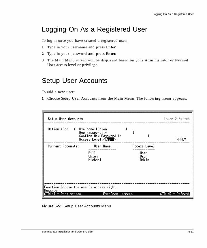
Summit24e2 Installation and User’s Guide 6-11
Logging On As a Registered User
Logging On As a Registered User
To log in once you have created a registered user:
1 Type in your username and press Enter.
2 Type in your password and press Enter.
3 The Main Menu screen will be displayed based on your Administrator or NormalUser access level or privilege.
Setup User Accounts
To add a new user:
1 Choose Setup User Accounts from the Main Menu. The following menu appears:
Figure 6-5: Setup User Accounts Menu

6-12 Summit24e2 Installation and User’s Guide
Using the Console Interface
2 Toggle the Action:<Add> field using the space bar to choose Add, Update, or Delete.
3 Type in the Username for the user account you wish to add.
4 Enter the New Password for that user account.
5 Enter the same password again in Confirm New Password to confirm the choice ofpassword.
6 Choose the privilege level by toggling the Access Level:<Root> field until theappropriate level is displayed - Root, User+ or User.
7 Highlight APPLY and press enter to make the change effective.
8 You must enter the configuration changes into the non-volatile RAM (NV-RAM)using Save Changes from the Main Menu if you want the configuration to be usedafter a switch reboot.
9 Press Esc to return to the previous screen or Ctrl+T to go to the root screenType inyour Username and press Enter.
Modifying user names and password for user accounts can only be done by a Root-leveluser.
Update/Delete User Accounts
Access to the console, whether using the console port or via TELNET, is controlledusing a user name and password. Up to eight of these user names can be defined. Theconsole interface will not let you delete the current logged-in user, however, in order toprevent accidentally deleting all of the users with Root privileges.
Only users with the Root privilege can delete users.
To view a user account:
Choose Setup User Accounts from the Main menu. The following screen appears:

Summit24e2 Installation and User’s Guide 6-13
Setting Up the switch
Figure 6-6: View/Delete User Accounts Menu
To delete a user:
1 Toggle the Action:<Delete> field using the space bar to choose Add, Update, orDelete.
2 Type in the Username for the user account you wish to delete.
3 Select APPLY and press Enter to let the user deletion take effect.
Setting Up the switch
switch management functions are grouped into two major groups in the console, BasicSetup and Advanced functions. The remaining sections of this chapter deal with howyou can use the console to setup these functions to implement an efficient networkmanagement strategy.

6-14 Summit24e2 Installation and User’s Guide
Using the Console Interface
Basic Setup
This section will help prepare the switch user by describing the following menus andtheir sub-menus:
• Switch Information
• Basic Network Setup
• Serial Port Settings
• Configure Ports
• Setup User Account
• Network Management Setup
— SNMP Configuration
— Management Station IP Setup
• Utilities
— Download Firmware from TFTP Server
— Download Configuration from TFTP Server
— Upload Settings to TFTP Server
— Upload History Log to TFTP Server
— Ping Test
• Network Monitoring
— Port Utilization
— Port Error Packets
— Port Packet Analysis
— Browse MAC Address
— Browse ARP Table
— Browse Routing Table
— Browse Router Port
— IGMP Snooping
— switch History
• Save Changes
• System Reboot

Summit24e2 Installation and User’s Guide 6-15
Basic Setup
• Logout
Switch Information
Choose switch Information to access the first item on the Summit24e2 Main Menu. Thefollowing menu appears:
Figure 6-7: Switch Information Menu
The switch Information menu displays the type of switch (Summit24e2), which (if any)external modules are installed, and the switch's MAC address (assigned by the factoryand unchangeable). In addition, the Boot PROM and Firmware Version numbers areshown. This information is helpful to keep track of PROM and Firmware updates andto obtain the switch's MAC address for entry into another network device's addresstable - if necessary.
You can also enter the name of the system, its location, and the name and telephonenumber of the System Administrator. It is recommended that the person responsible forthe maintenance of the network system that this switch is installed on be listed here.

6-16 Summit24e2 Installation and User’s Guide
Using the Console Interface
Basic Network Setup
Some settings such as the switch IP address and subnet mask must be entered to allowthe switch to be managed from an SNMP-based Network Management System or to beable to access the switch using the TELNET protocol.
The Basic Network Setup menu lets you specify how the switch will be assigned an IPaddress to allow the switch to be identified on the network. In addition, you mayspecify a subnet mask and default gateway.
Highlight Basic Network Setup to access the first item on the Configuration menu. Thefollowing screen appears:
Figure 6-8: Basic Network Setup Menu
The fields listed under the New switch Settings heading are those that are currentlybeing used by the switch. Those fields listed under the Restart Settings heading arethose which will be used after the switch has been reset. Fields that can be set are:

Summit24e2 Installation and User’s Guide 6-17
Basic Setup
Get IP AddressFrom
Determines whether the switch should get its IP addresssettings from the user (Manual), a BOOTP server, or aDHCP server. If Manual is chosen, the switch will use theIP address, Subnet Mask and Default Gateway settingsdefined in this screen after saving the changes andrebooting. If BOOTP is chosen, the switch will send out aBOOTP broadcast request when it is powered up. TheBOOTP protocol allows IP addresses, network masks, anddefault gateways to be assigned by a central BOOTPserver. If this option is set, the switch will get its IPsettings from the BOOTP server upon being rebooted. IfDHCP is chosen, a Dynamic Host Configuration Protocolrequest will be sent when the switch is rebooted.
IP Address Determines the IP address used by the switch forreceiving SNMP and TELNET communications. Thesefields should be of the form xxx.xxx.xxx.xxx, where eachxxx is a number (represented in decimal) between 0 and255. This address should be a unique address on anetwork assigned to you by the central Internetauthorities.
Subnet Mask Bitmask that determines the extent of the subnet that theswitch is on. Should be of the form xxx.xxx.xxx.xxx,where each xxx is a number (represented in decimal)between 0 and 255. If no subnetting is being done, thevalue should be 255.0.0.0 for a Class A network,255.255.0.0 for a Class B network, and 255.255.255.0 for aClass C network.
Default Gateway IP address that determines where frames with adestination outside the current IP subnet should be sent.This is usually the address of a router or a host acting asan IP gateway. If your network is not part of aninter-network, or you do not want the switch to beaccessible outside your local network, you can leave thisfield unchanged.
ManagementVLAN Name
Allows a management VLAN Name to be entered. Thisallows switch management from a host within that VLANto use either TELNET or an SNMP-based networkmanager. The default VLAN Name is default whichincludes the entire switch until VLANs are configured.

6-18 Summit24e2 Installation and User’s Guide
Using the Console Interface
Configuring the Serial Port
You can use the Serial Port Settings screen to enter settings for the switch’s RS-232Cserial port for console management.
To configure the serial port, highlight Serial Port Settings from the Main Menu andpress Enter. The following screen appears:
Figure 6-9: Serial Port Settings Screen
The following fields can then be set:
Baud Rate Displays the serial bit rate that will be used tocommunicate with the management host. The defaultsetting is 9600, and cannot be changed.
Data Bits Displays the number of bits in the data stream that willrepresent data. The default is 8 data bits and cannot bechanged.

Summit24e2 Installation and User’s Guide 6-19
Basic Setup
Flow Control:<None>
Sets the flow control scheme for the switch’s RS-232Cport. Can be set to None, or XOn/XOff. This setting mustmatch the setting on the host computer’s RS-232C port,and is set to None by default.
Auto-Logout Sets the time the interface can be idle before the switchautomatically logs-out the user. The options are 2 mins, 5mins, 10 mins, 15 mins, or Never.
Configure Ports
The Configure Ports screen allows you to change port state, the speed/duplexcombination and flow control of all ports. If you are configuring Gigabit Ethernet ports,use the same screen. The options for configuring Gigabit Ethernet ports differ from the10/100 Mbps ports, therefore instructions for configuring the Gigabit ports arepresented in a separate section below. To configure the 10/100 Mbps ports, highlightPort Configuration on the Main Menu and the following screen will appear:
Figure 6-10: Configure Ports Screen

6-20 Summit24e2 Installation and User’s Guide
Using the Console Interface
Configure the ports by selecting options in the following fields:
View Ports Toggle the View Ports:< > field, using the space bar, toview the configuration of ports 1-12, ports 13-24 orSlot-1. To configure the Slot Module ports, see theinstructions below.
Configure Portsfrom [ ] to [ ]
To configure a specific port, or a sequential group of portswithin the range defined in the View Ports field, use theConfigure Port from [ ] to [ ] field. To configure a singleport, type the port number in both the upper and lowerlimit of the range.
State Toggle the State:< > field to either Enable or Disable thespecified port or sequential port group.
Speed/Duplex Toggle the Speed/Duplex:< > field to select the speed andduplex state of the port. Auto - auto-negotiation,negotiates settings for operation with 10 and 100 Mbpsdevices, in full- or half-duplex modes. The Auto settingallows the port to automatically determine the fastestsettings of the device to which the port is connected, andthen to use those settings. For the 24 copper ports chooseAuto, 100M/Full, 100M/Half, 10M/Full, 10M/Half.There is no automatic adjustment of port settings withany option other than Auto.
Flow Control For 10/100 Mbps ports configured as half-duplex,backpressure is always enabled.
For 10/100 Mbps ports configured as full-duplex, no flowcontrol is supported.
Configure the Gigabit Ethernet Ports
You can configure the Gigabit Ethernet ports using the Configure Ports Screen. Thenature of Gigabit Ethernet requires that additional factors be considered duringconfiguration In addition, the type of port will effect how these settings function.
Configure the Gigabit Ethernet ports using the same fields in the Configure Ports screenwith the following considerations:
View Ports Toggle the View Ports:< > field to select Slot-1.

Summit24e2 Installation and User’s Guide 6-21
Basic Setup
Configure Portsfrom [ ] to [ ]
Use the Configure Port from [ ] to [ ] field to configureone or both of the Slot 1 ports. Enter 1 for Slot ModulePort 1 (S1P1), and 2 for Slot Module Port 2 (S1P2).
State Toggle the State:< > field to either Enable or Disable thespecified port or ports.
Speed/Duplex For most circumstances, the default setting Auto will beappropriate. However, if the switch is used on a networkthat employs certain older Gigabit Ethernet devices, itmay be necessary to force 1000 Mbps full-duplexoperation. Consult the specifications of these olderdevices for more information. In addition, the type of porteffects how the Auto setting functions. 1000BASE-TXports are capable of true Auto-negotiation in that they canoperate at 10, 100 or 1000 Mbps and in full- or half-duplexmode. GBIC ports will only operate at 1000 Mbps infull-duplex mode. Toggle the Speed/Duplex:< > field toeither select the either Auto or 1000MFULL.
Flow Control For 1000 Mbps ports, flow control can be disabled. If theFlow Control:<Off> field is toggled to “Rx”, then theSummit24e2 switch will not transmit 802.3x PAUSEframes when it becomes congested, but will honor PAUSEframes it receives from another switch’s connected port.

6-22 Summit24e2 Installation and User’s Guide
Using the Console Interface
Network Management Setup
Highlight Network Management Setup from the Main Menu and press Enter.
Figure 6-11: Network Management Setup
SNMP Configuration
Highlight SNMP Configuration from the Network Management Setup Menu andpress Enter.

Summit24e2 Installation and User’s Guide 6-23
Basic Setup
Figure 6-12: SNMP Configuration
Setting Trap Receivers
The Setup Trap Receivers feature allows the switch to send traps (messages abouterrors, etc.) to management stations on the network. Highlight Setup Trap Receiversand press Enter. The trap recipients can be setup from the following screen:

6-24 Summit24e2 Installation and User’s Guide
Using the Console Interface
Figure 6-13: Setup SNMP Trap Recievers Menu
Fields that can be set in the Setup Trap Recipients menu include:
IP Address The IP address of a management station (usually acomputer) that is configured to receive the SNMP trapsfrom the switch.
SNMP CommunityString
Similar to a password in that stations that do not knowthe correct string cannot receive or request SNMPinformation from the switch.
Status Toggle between Enabled and Disabled to enable or disablethe receipt of SNMP traps by the listed managementstations.
Up to four SNMP trap recipients can be entered.

Summit24e2 Installation and User’s Guide 6-25
Basic Setup
Management Station IP Address Setup
The switch allows you to specify up to four IP addresses that are allowed to manage theswitch via in-band SNMP or TELNET based management software. These IP addressesmust be members of the Management VLAN.
If no IP addresses are specified, then there is nothing to prevent any IP address fromaccessing the switch, provided the user knows the Username and Password.
Highlight Management Station IP Setup from the SNMP Configuration Menu and pressEnter.
Figure 6-14: Management Station IP Setup
Switch Utilities
When it is necessary to upgrade firmware or use a saved switch configuration filelocated on a TFTP (Trivial File Transfer Protocol) server, use the switch Utilities menu toperform these operations. Additionally, you can save switch configuration files andswitch history logs to a TFTP server. The switch Utilities menu is also where you canperform a Ping test to confirm connectivity and communication with other devices onthe network.
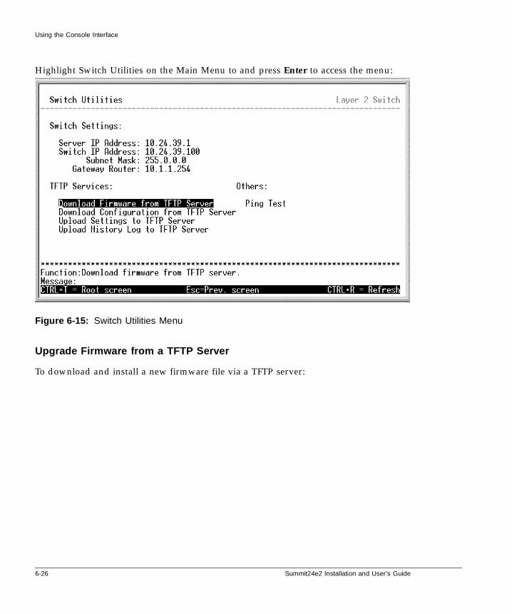
6-26 Summit24e2 Installation and User’s Guide
Using the Console Interface
Highlight Switch Utilities on the Main Menu to and press Enter to access the menu:
Figure 6-15: Switch Utilities Menu
Upgrade Firmware from a TFTP Server
To download and install a new firmware file via a TFTP server:

Summit24e2 Installation and User’s Guide 6-27
Basic Setup
Highlight Upgrade Firmware from TFTP Server on the switch Utilities Menu and pressEnter to see the Upgrade Firmware screen:
Figure 6-16: Download Firmware from TFTP Server
Trivial File Transfer Protocol (TFTP) services allow the switch firmware to beupgraded by transferring a new firmware file from a TFTP server to the switch.A configuration file can also be loaded into the switch from a TFTP server,switch settings can be saved to the TFTP server, and a history log can beuploaded from the switch to the TFTP server.
Enter the IP address of the TFTP server in the Server IP address:[ ] field.
The TFTP server must be on the same IP subnet as the switch.
Enter the path and the filename to the firmware file on the TFTP server in thePath\Filename: [ ] field. In the above example, the firmware file is in the rootdirectory of the C drive of the TFTP server.

6-28 Summit24e2 Installation and User’s Guide
Using the Console Interface
The TFTP server must be running TFTP server software to perform the filetransfer. TFTP server software is a part of many network management softwarepackages, or can be obtained as a separate program.
4 Highlight APPLY and press Enter to record the IP address of the TFTP server.
5 Highlight START and press Enter to initiate the file transfer.
Download a Configuration File From a TFTP Server
Downloading a configuration file from a TFTP server is a procedure similar toupgrading firmware via a TFTP server. To download a switch configuration file from aTFTP server:
1 Highlight Use Configuration File on TFTP Server on the switch Utilities Menu andpress Enter.
Figure 6-17: Download Configuration from TFTP Server

Summit24e2 Installation and User’s Guide 6-29
Basic Setup
2 Enter the IP address of the TFTP server in the Server IP address:[ ] field
3 Specify the location of the switch configuration file on the TFTP server in thePath\Filename:[ ] field.
4 Highlight APPLY and press Enter to record the IP address of the TFTP server.
5 Highlight START and press enter to initiate the file transfer.
Save Configuration File to a TFTP Server
If you wish to save the current switch configuration settings, you have two options. Youcan save the settings to a defined section as described in Configure Section Settings, oryou can upload the settings to a file on a TFTP server.
Note: uploading the current configuration settings will upload the settings that arenow defined on the switch even if they have not been saved to NV-RAM.
To upload the current switch settings:
Highlight Save Settings to TFTP Server on the switch Utilities Menu and press Enter.
Figure 6-18: Upload Settings to TFTP Server Menu

6-30 Summit24e2 Installation and User’s Guide
Using the Console Interface
6 Enter the IP address of the TFTP server in the Server IP address:[ ] field.
7 Specify the location for the switch configuration file on the TFTP server in thePath\Filename:[ ] field.
8 Highlight APPLY and press Enter to record the IP address of the TFTP server.
9 Highlight START and press enter to initiate the file transfer.
Save switch History to TFTP Server
If you wish to save the a switch history log to a TFTP server:
1 Highlight Save History Log to TFTP Server on the switch Utilities Menu and pressEnter.
Figure 6-19: Upload History Log to TFTP Server
2 Enter the IP address of the TFTP server in the Server IP Address:[ ] field.
3 Specify the location for the switch configuration file on the TFTP server in thePath\Filename:[ ] field.

Summit24e2 Installation and User’s Guide 6-31
Basic Setup
4 Highlight APPLY and press Enter to record the IP address of the TFTP server.
5 Highlight START and press enter to initiate the file transfer.
Ping Test
The switch can be used to test conduct Ping tests. To perform a Ping test:
1 Highlight Ping Test on the switch Utilities Menu and press Enter.
Figure 6-20: Ping Test
2 In the Ping test screen, enter the IP address of the network device to be pinged in theIP Address: [ ] field.
3 Enter the number of test packets to be sent (3 is usually enough).
4 Highlight START and press enter to initiate the ping program.
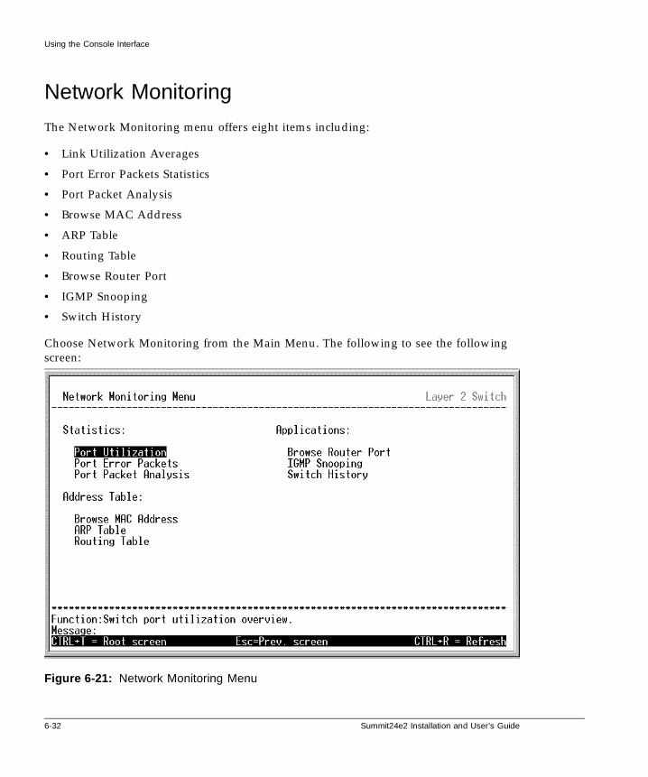
6-32 Summit24e2 Installation and User’s Guide
Using the Console Interface
Network Monitoring
The Network Monitoring menu offers eight items including:
• Link Utilization Averages
• Port Error Packets Statistics
• Port Packet Analysis
• Browse MAC Address
• ARP Table
• Routing Table
• Browse Router Port
• IGMP Snooping
• Switch History
Choose Network Monitoring from the Main Menu. The following to see the followingscreen:
Figure 6-21: Network Monitoring Menu

Summit24e2 Installation and User’s Guide 6-33
Network Monitoring
Link Utilization Averages
To view the link utilization averages, highlight Link Utilization Averages on theNetwork Monitoring menu and press Enter.
Figure 6-22: Link Utilization Averages
The Link Utilization Averages screen displays the number of packets transmitted andreceived per second and calculates the percentage of the total available bandwidthbeing used on the port (displayed under %Util.).
The Interval at which the displayed statistics are refreshed may be changed byhighlighting Interval: < > and toggling to select <2 sec>, <5 sec>, <15 sec>, <30 sec>,<1 min> and <Suspend>.

6-34 Summit24e2 Installation and User’s Guide
Using the Console Interface
Port Error Statistics
To view the error statistics for a port, highlight Port Error Packets on the NetworkMonitoring menu and press Enter.
Figure 6-23: Port Error Statistics
Use the Module:<Base Unit> field to toggle either Base Unit or Slot-1 to select whichgroup of ports will be displayed. The Gigabit Ethernet ports are in Slot-1.
Enter the port number of the port to be viewed in the Port: [ ] field. The Interval:< >field can be toggled from 2 seconds to 1 minute, or suspend. This sets the interval atwhich the error statistics are updated.
The following are definitions of the terms used in the Port Error Statistics menu:
Interval:<2 sec> The interval (in seconds) that the table is updated. Thedefault is 2 seconds.
RX Frames The number of packets recieved.

Summit24e2 Installation and User’s Guide 6-35
Network Monitoring
CRC Error For 10 Mbps ports, the counter records CRC errors (FCSor alignment errors), for 100 Mbps ports, the counterrecords the sum of CRC errors and code errors (framesreceived with rxerror signal).
Undersize The total number of frames received that were less than 64octets long (excluding framing bits, but including FCSoctets) and were otherwise well formed.
Oversize The total number of frames received that were longer than1518 octets (excluding framing bits, but including FCSoctets) and were otherwise well formed.
Fragments The total number of frames recieved that were less than 64octets in length (excluding framing bits, but includingFCS octets) and had either an FCS or an alignment error.
Jabber The total number of frames received that were longer than1518 octets (excluding framing bits, but including FCSoctets), and had either an FCS or an alignment error.
Drop Pkts The total number of frames for which the firsttransmission attempt on a particular interface wasdelayed because the medium was busy.
CRC Error For 10 Mbps ports, the counter records CRC errors (FCSor alignment errors). For 100 Mbps ports, the counterrecords the sum of CRC errors and code errors (framesreceived with rxerror signal).
Late Coll. Late Collisions — the number of times that a collision isdetected later than 512 bit-times into the transmission of apacket.
Ex. Coll. Excessive Collisions — the number of frames for whichtransmission failed due to excessive collisions.
Single Coll. Single Collision Frames — the number of successfullytransmitted frames for which transmission is inhibited bymore than one collision.
Coll. An estimate of the total number of collisions on thisnetwork segment.

6-36 Summit24e2 Installation and User’s Guide
Using the Console Interface
Port Packet Analysis
The Port Packet Analysis table displays the size of packets received or transmitted by agiven switch port. In addition, statistics on the number and rate of unicast, multicast,and broadcast packets received by the switch are displayed.
To view the Port Packet Analysis Screen, highlight Port Packet Analysis on the NetworkMonitoring Menu.
Figure 6-24: Port Packet Analysis
In addition to the size of packets received or transmitted by the selected port, statisticson the number of unicast, multicast, and broadcast packets are displayed. Toggle toselect the Base Unit or Slot-1 in the Module field. Choose the Port number for whichyou wish to view statistics and Interval to refresh the screen.
The following are definitions of the terms used in the Port Packet Analysis menu:
Interval:<2 sec> The interval (in seconds) that the table is updated. Thedefault is 2 seconds.

Summit24e2 Installation and User’s Guide 6-37
Network Monitoring
Frames Displays the number of frames received or transmitted bythe switch with the size, in octets, given by the column onthe right.
Frames/sec The number of frames transmitted or received, persecond, by the switch.
Unicast RX The number of unicast packets received by the switch intotal number (under Frames) and by rate (underFrames/sec).
Multicast RX The number of multicast packets received by the switch intotal number and by rate.
Broadcast RX The number of broadcast frames received by the switch intotal number and by rate.
RX Bytes The number of bytes (octets) received by the switch intotal number and by rate.
RX Frames The number of frames received by the switch in totalnumber and by rate.
TX Bytes The number of bytes (octets) transmitted by the switch intotal number and by rate.
TX Frames The number of frames transmitted by the switch in totalnumber and by rate.
MAC Address Forwarding Table
To view the MAC address forwarding table, highlight Browse MAC Address on theNetwork Monitoring menu and press Enter.

6-38 Summit24e2 Installation and User’s Guide
Using the Console Interface
Figure 6-25: Browse MAC Address
The Browse By:<ALL> field can be toggled between ALL, MAC Address, Port, andVLAN. This sets a filter to determine which MAC addresses from the forwarding tableare displayed. ALL specifies no filter.
To search for a particular MAC address:
Toggle the Browse By:<ALL> field to MAC Address. A MAC Address:[000000000000]field will appear. Enter the MAC address in the field and press Enter.
Browse the ARP Table
To view the switch’s Address Resolution Protocol (ARP) table, highlight ARP Table onthe Network Monitoring menu and press Enter.

Summit24e2 Installation and User’s Guide 6-39
Network Monitoring
Figure 6-26: Browse ARP Table
To display a particular IP address, enter the IP address in the Jump to IPAddress:[0.0.0.0] field, highlight GO and press Enter.
Browse the Routing Table
To view the contents of the switch’s routing table, highlight Routing Table on theNetwork Monitoring menu and press Enter.

6-40 Summit24e2 Installation and User’s Guide
Using the Console Interface
Figure 6-27: Browse Routing Table
To display a particular destination IP address, enter the IP address in the Jump toDestination Address:[0.0.0.0], the corresponding subnet mask in the Mask:[0.0.0.0] field,and the gateway address in the Gateway:[0.0.0.0] field, highlight GO and press Enter.
Browse Router Port
This displays which of the switch’s ports are currently configured as router ports. Arouter port configured by a user (using the management console) is designated as astatic router port, displayed using an “S”. A router port that has been dynamicallyconfigured by the switch is displayed using a “D”.
To view the router port table, highlight Browse Router Port from the NetworkMonitoring menu and press Enter.
A router port is simply a port that has a multicast router connected to it. Generally, thisrouter would have a connection to a WAN or to the Internet.

Summit24e2 Installation and User’s Guide 6-41
Network Monitoring
Figure 6-28: Browse Router Port
The Jump to VLAN Name:[default] field allows the entry of a VLAN name for anyVLAN configured on the switch. Enter the name of the VLAN, highlight GO and pressEnter.
All of the ports that have been designated as router ports, for the specified VLAN, willbe indicated with an “S” — for staticly configured router ports, or a “D” — for routerports that are dynamically configured by the switch.
IGMP Snooping Status
This allows the switch’s IGMP snooping table to be viewed. IGMP snooping allows theswitch to read the multicast group address from IGMP packets that pass through theswitch. The ports where the IGMP packets were snooped are displayed using an “M”.the number of IGMP reports that were snooped are also displayed in the Reports: field.
To view the IGMP snooping table, highlight IGMP Snooping Status from the NetworkMonitoring menu and press Enter.

6-42 Summit24e2 Installation and User’s Guide
Using the Console Interface
Figure 6-29: IGMP Snooping Status
The IGMP settings for the switch are also displayed.
Switch History Log
This allows the switch history log to be viewed. The switch records all traps, insequence, that identify events on the switch since the last cold boot of the switch. Acold boot (power down and restart) erases the switch’s history log.
To view the switch history log, highlight switch History from the Network Monitoringmenu and press Enter.

Summit24e2 Installation and User’s Guide 6-43
Reboot
Figure 6-30: Switch History
Reboot
The Summit24e2 switch offers several options to reboot the switch. The switch can berebooted without entering the current configuration into NV-RAM, in which case allsettings not saved with the Save Changes command will be lost. Or the switch can enterthe current configuration into NV-RAM and then reboot.
In addition, there are two options to return the switch’s configuration to the defaultvalues entered at the factory. The full factory default values (including the default IPaddress and subnet mask) can be loaded into NV-RAM, or the factory default valuesexcept the user-defined IP address can be loaded.
The factory defaults are listed in Appendix B of this manual.
The System Reboot menu is shown in Figure 6-31 below.
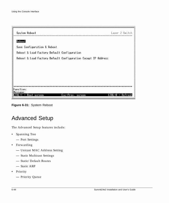
6-44 Summit24e2 Installation and User’s Guide
Using the Console Interface
Figure 6-31: System Reboot
Advanced Setup
The Advanced Setup features include:
• Spanning Tree
— Port Settings
• Forwarding
— Unicast MAC Address Setting
— Static Multicast Settings
— Static/Default Routes
— Static ARP
• Priority
— Priority Queue

Summit24e2 Installation and User’s Guide 6-45
Advanced Setup
— Setup MAC Address Priority
• Mirroring
— Target Port Selection
— Port Mirroring Settings
• IGMP Configuration
— switch IGMP Snooping
— IGMP Snooping Settings
— Static Router Port Settings
• VLANs
— Edit VLANs
• Link Aggregation
• Exception Handling
Configuring the Spanning Tree Protocol
The Spanning Tree protocol is used to prevent loops in a network in which alternativeconnections exist between switches. The Protocol Parameters allow you to change thebehind the scene parameters of the Spanning Tree Protocol at the bridge level. Theparameters for this section have been fully explained in “STA Operation Levels” onpage 5-9 and “User-Changeable STA Parameters” on page 5-11. It is recommended thatyou read these sections, as well as “Spanning Tree Algorithm” on page 5-8 beforechanging any of the parameters.
The factory default settings should cover the majority of installations. However, itis advisable to keep the default settings as set at the factory; unless, it isabsolutely necessary.
STP Parameter Settings
To globally configure the Protocol Parameters:
Choose Spanning Tree from the Main Menu appearing under Advanced Setup. Thefollowing Configure Spanning Tree Protocol menu will be displayed:

6-46 Summit24e2 Installation and User’s Guide
Using the Console Interface
Figure 6-32: Configure Spanning Tree Menu
The user-changeable parameters in the switch are as follows:
Status Allows the spanning tree algorithm to be Disabled orEnabled, globally for the switch.
Max Age The Max. Age can be set from 6 to 40 seconds. At the endof the Max. Age, if a BPDU has still not been receivedfrom the Root Bridge, your switch will start sending itsown BPDU to all other switches for permission to becomethe Root Bridge. If it turns out that your switch has thelowest Bridge Identifier, it will become the Root Bridge.
Hello Time Hello Time:[ ] The Hello Time can be set from 1 to 10seconds. This is the interval between two transmissionsof BPDU packets sent by the Root Bridge to tell all otherswitches that it is indeed the Root Bridge. If you set aHello Time for your switch, and it is not the Root Bridge,the set Hello Time will be used if and when your switchbecomes the Root Bridge.

Summit24e2 Installation and User’s Guide 6-47
Advanced Setup
Forward Delay Forward Delay:[ ] The Forward Delay can be from 4 to 30seconds. This is the time any port on the switch spends inthe listening state while moving from the blocking state tothe forwarding state.
Priority Priority:[ ] A Priority for the switch can be set from 0 to65535. 0 is equal to the highest Priority. This number isused in the voting process between switches on thenetwork to determine which switch will be the rootswitch. A low number indicates a high priority, and ahigh probability that this switch will be elected as the rootswitch.
Observe the following formulas when setting theSpanning Tree parameters:
Max. Age = 2 x (Forward Delay - 1 second)
Max. Age = 2 x (Hello Time + 1 second)
The Hello Time cannot be longer than the Max. Age.Otherwise, a configuration error will occur.
Port Spanning Tree Settings
To configure STP port settings, toggle the View Ports:< > field to the range of portsto be configured. The Fast Ethernet ports displayed for configuration in groups of 12and the two Gigabit Ethernet ports are displayed together. Select the port(s) to beconfigured in the Configure Port from [ ] to [ ] field.

6-48 Summit24e2 Installation and User’s Guide
Using the Console Interface
Figure 6-33: Spanning Tree Port Settings Menu
The Port Group STP parameters that can be configured are:
Port Cost A Port Cost can be set from 1 to 65535. The lower thenumber, the greater the probability the port will be chosento forward packets.
Priority A Port Priority can be from 0 to 255. The lower thenumber, the greater the probability the port will be chosenas the Root Port.
State:<Disabled> Allows the spanning tree protocol to be Disabled orEnabled for an individual port, or a group of ports, asselected above.
Forwarding
When an incoming packet is processed in the switch, the forwarding table is consultedin order to decide how to handle the packet. Specifically, the switch must decide to

Summit24e2 Installation and User’s Guide 6-49
Advanced Setup
either filter the packet off the network or to forward it through the port and VLAN (ifenabled) on which its destination lies.
Dynamic MAC forwarding and MAC filtering are functions of the Learning Process, orthe process of observing network traffic. The Learning Process is an automatic andcontinuous function of the switch, the only variable that can be configured for thisprocess is the MAC address age out time. Static MAC forwarding uses static entries thatmay be added and removed from the database by the user. They are not automaticallyremoved by any age-out mechanism.
The MAC Forwarding and IP Forwarding screens allow you to stop or start addresslearning for specified MAC addresses and change the way the switch treats MACaddress table entries.
MAC Address Aging Time
Highlight Forwarding Menu from the Main Menu and press Enter.
Figure 6-34: Forwarding Menu

6-50 Summit24e2 Installation and User’s Guide
Using the Console Interface
The following fields can then be set:
MAC AddressAging
Time(sec):[300]
This field specifies the length of time a learned MACAddress will remain in the forwarding table withoutbeing accessed (that is, how long a learned MAC Addressis allowed to remain idle). The Aging Time can be set toany value between 10 and 1,000,000 seconds. The defaultis 300 seconds
Note: a very long Aging Time can result with the out-of-date Dynamic Entriesthat may cause incorrect packet filtering/forwarding decisions. A very shortaging time may cause entries to be aged out to soon, resulting in a highpercentage of received packets whose source addresses cannot be found in theaddress table, in which case the switch will broadcast the packet to all ports,negating many of the benefits of having a switch.
Broadcast/Multicast Storm Control
Highlight Broadcast/Multicast Storm Control from the Forwarding menu and pressEnter.
Figure 6-35: Broadcast/Multicast Storm Control Menu

Summit24e2 Installation and User’s Guide 6-51
Advanced Setup
Use the entry fields described below for the parameters that control how the switch willreact to broadcast and multicast storms.
The switch ports are grouped in the following groups:
• Group 1 - ports 1 through 8
• Group 2 - ports 9 through 16
• Group 3 - ports 17 through 24
• Group 4 - Gigabit port 25
• Group 5 - Gigabit port 26
The following fields can be set:
Upper Threshold(Kbp):[128]
This is the number of Broadcast/Multicast in Kbsreceived by the switch that will trigger the switch'sreaction to a Broadcast/Multicast storm.
Broadcast StormMode:<Disabled>
Toggle to select Enabled or Disabled using the space barto globally enable or disable the switch's reaction toBroadcast storms, triggered at the threshold set above.
Multicast StormMode:<Disabled>
This field can be toggled between Enabled and Disabledusing the space bar. This enables or disables, globally, theswitch's reaction to Multicast storms, triggered at thethreshold set above.
Highlight APPLY and press Enter to apply the Multicast Forwarding settings. Use theSave Changes menu to save the settings to NV-RAM.
Unicast MAC Address Forwarding
Highlight Unicast MAC Address Setting from the Forwarding Menu and press Enter.

6-52 Summit24e2 Installation and User’s Guide
Using the Console Interface
Figure 6-36: Unicast MAC Address Setting Menu
The following fields can be set:
Action:<Add/Modify>
Toggle to choose Add/Modify or Delete to add, change ordelete an entry.
VLAN Name: [ ] The name of the VLAN on which the MAC addressresides.
MAC Address:[000000000000]
The MAC address to be added to the static forwardingtable. Below the entry fields in the menu, a display of atotal of ten destination addresses per page can be seen.The switch can hold up to 256 entries.
Port:[ ] The port number corresponding to the MAC destinationaddress. The switch will always forward traffic to thespecified device through this port.

Summit24e2 Installation and User’s Guide 6-53
Advanced Setup
Type:<Static> Can be toggled between Static, and BlackHole using thespace bar. Static enters the MAC address into the switch’sunicast forwarding table. BlackHole causes all packetswith the specified MAC address as their destingation tobe dropped.
Highlight APPLY and press Enter to apply the Multicast Forwarding settings. Use theSave Changes menu to save the settings to NV-RAM.
Multicast MAC Address Forwarding
Highlight Static Multicasting Forwarding from the Forwarding Menu and press Enter.
Figure 6-37: Static Multicast Settings Menu
The following fields can be set:
Action:<Add/Modify>
Toggle to choose Add/Modify or Delete to add, change ordelete an entry.

6-54 Summit24e2 Installation and User’s Guide
Using the Console Interface
VLAN Name: [ ] The name of the VLAN on which the MAC addressresides.
Multicast MACAddress:
[000000000000]
The multicast MAC address to be added to the staticforwarding table. Below the entry fields in the menu, adisplay of a total of ten destination addresses per pagecan be seen. The switch can hold up to 256 entries.
Port:(E/-):[ ][ ][ ] A port number should be chosen for each correspondingdestination address. The switch will always forwardtraffic to the specified device through this port.
Each port can be an Egress, Forbidden, or a Non-memberof the multicast group, on a per-VLAN basis.
To set a port's multicast group membership status,highlight the first field of Port:(E/-): [ ][ ][ ]. Each port'smulticast group membership can be set individually byhighlighting the port's entry using the arrow keys, andthen toggling between E, F, or - using the space bar. Usethe following definitions to guide you:
E — Egress membership specifies the port as being a staticmember of the multicast group. Egress Member Ports areports that will be transmitting traffic for the multicastgroup.
- — Non-member status specifies the port as not being amember of the multicast group, but the port can become amember of the multicast group dynamically.
Type:<Dynamic> Can be toggled between Dynamic, Static, and BlackHoleusing the space bar.
Highlight APPLY and press Enter to apply the Multicast Forwarding settings. Use theSave Changes menu to save the settings to NV-RAM.

Summit24e2 Installation and User’s Guide 6-55
Advanced Setup
Priority
Highlight Priority from the Main Menu and press Enter.
Figure 6-38: Priority Menu
Priority Queue Configuration
The Summit24e2 switch has 4 priority queues. These priority queues are numberedfrom Q0 — the lowest priority queue — to Q3 — the highest priority queue. The eightpriority queues specified in IEEE 802.1p (Q0 to Q7) are mapped to the switch’s priorityqueues as follows:
• Q1 and Q0 are assigned to the switch’s Q0 queue.
• Q3 and Q2 are assigned to the switch’s Q1 queue.
• Q5 and Q4 are assigned to the switch’s Q2 queue.
• Q7 and Q6 are assigned to the switch’s Q3 queue.

6-56 Summit24e2 Installation and User’s Guide
Using the Console Interface
The switch’s four priority queues are emptied in a round-robin fashion — begining withthe highest priority queue, and proceeding to the lowest priority queue before returningto the highest priority queue.
To configure the switch’s priority queing, highlight Priority Queue from the PriorityMenu and press Enter.
Figure 6-39: Priority Queue Configuration Menu
The priority queues are numbered in the order of the lowest priority queue — Q0 — tothe highest priority queue — Q3.
The MAX. Packets field specifies the number of packets that a que will transmit beforesurrendering the transmit buffer to the next lower priority queue in a round-robinfashion.
The MAX. Latency field specifies the maximum amount of time — in multiples of 16microseconds — that a queue will have to wait before being given access to the transmitbuffer. The MAX. Latency is a priority que timer. When it expires, it overides theround-robin and gives the priority que that it was set for access to the transmit buffer.

Summit24e2 Installation and User’s Guide 6-57
Advanced Setup
There is a small amount of additional latency introduced because the priority que that istransmitting at the time the MAX. Latency time expires will finish transmitting itscurrent packet before giving up the transmit buffer.
The following fields can be set:
Queue Number Allows the selection of any one of the four priority queuesavailable on the switch. Q0 is the lowest priority que. Q3is the highest priority que.
MAX. Packets(Packet)
Allows the specification of between 0 and 255 packets thatwill be transmitted by the specified que before the nextlower priority que is allowed to transmit packets.
MAX. Latency (+16microseconds)
Allows the specification of the maximum latency ofbetween 0 and 255 multiples of 16 microseconds. Thisestablishes a priority que timer that overides theround-robin and allows the priority que (for which thetimer was set) the next access to the transmit buffer.
If all of the MAX. Packets and MAX Latency fields — for all four priority queues — areset to zero, then the priority queues are emptied in a strict priority round-robin. Q3 (thehighest priority que) will transmit all of the packets it has accumulated before Q2 isallowed to transmit. Q2 will then transmit all of the packets it has accumulated beforeQ1 is allowed to transmit, and so on. Finally, when Q0 has transmitted all of the packetsit has accumulated, Q3 will again be allowed to transmit packets.
A strict priority round-robin priority scheme is recommended for most installations thatdo not have specific priority or latency requirments.
The MAX. Packets fields can be configured to provide control over the maximumnumber of packets that can be transmitted before a given priority que will be allowed totransmit its accumulated packets.
The resulting priority scheme is best illustrated using an example:
If the MAX. Packets fields for Q0, Q1, Q2, and Q3 are set to 2, 4, 8, and 12 respectively,then the priority queues are emptied as follows:
(assuming all queues have many packets to transmit)
1 The first 12 packets from Q3 will be sent.
2 8 packets from Q2 will be sent.

6-58 Summit24e2 Installation and User’s Guide
Using the Console Interface
3 4 packets from Q1 will be sent.
4 2 packets from Q0 will be sent.
5 12 more packets from Q3 will be sent, ... and so on.
In this example, Q2 will transmit 8 packets and then have a maximum of 18 packetstransmitted by the other queues before it can send 8 more packets.
The MAX. Packets fields should be either all zeros (strict priority) or non-zero forall priority queues.
If the MAX. Latency field for Q2 (in the above example) is set to 1, then a 16microsecond timer is set for Q2. When Q2 finishes sending its alloted 8 packets, thetimer starts. If 16 microseconds elapse before Q2 is again allowed to send 8 packets, thecurrently transmitting que is allowed to completly finish transmitting its current packet,and then the transmit buffer is given to Q2. Q2 can then transmit its next 8 packets.When Q2 is finished transmitting its alloted 8 packets, Q1 is then allowed to transmit itsalloted 4 packets, and so on.
The MAX. Latency should be set to a non-zero value for only one priority que.All other priority queues should have this field set to zero.
If a MAX. Latency timer is established for more than one priority que, it is possible thatthe timer will expire and overide the round-robin repeatadly such that only the two (ormore) queues for which a MAX. Latency timer has been defined are allowed to transmitpackets — leaving the other queues unable to send their full allotment of packets oreven unable to send any packets at all.
MAC Address Priority
The Summit24e2 switch allows packets sent to (or received from) specific MACaddresses to be assigned to one of the four priority queues configured above.
Highlight MAC Address Priority from the Priority Menu and press Enter.

Summit24e2 Installation and User’s Guide 6-59
Advanced Setup
Figure 6-40: Setup MAC Address Priority Menu
Action:<Add/Modify>
Toggle to choose Add/Modify or Delete to add, modify ordelete an entry.
VLANName:[default]
The name of the VLAN the MAC address entered belowbelongs to.
MAC Address:[000000000000]
The MAC address for which priority is to be set.
Priority Level:<1> Allows the selection of which of the four priority queuespackets with the above MAC address as their destinationaddress will be put in.
Source/Destination:<Src.>
Can be toggled between Scr. (Source), Dst. (Destination),and Either. This specifies the above MAC address as asource of packets to forward (packets coming into theswitch from this MAC address), a destination (packetsflowing out of the switch to this destination, or either(both a source and a destination.

6-60 Summit24e2 Installation and User’s Guide
Using the Console Interface
PriorityReplacement:
<Off>
Can be toggled between On and Off using the space bar.This specifies whether the switch should replace apacket’s existing priority tag with the priority specifiedabove. The priority specified above is used by the switchinternally, but the packet’s priority tag will remainunchanged (perhaps for use by a subsequent networkdevice) if Priority Replacement is set to Off. The packet’spriority tag will be changed to the priority set above, ifPriority Replacement is set to On.
Port Mirroring
The switch allows you to copy frames transmitted and received on a port and redirectthe copies to another port. You can attach a monitoring device to the mirrored port,such as a sniffer or an RMON probe to view details about the packets passing throughthe first port. This is useful for network monitoring and troubleshooting purposes.
Choose Mirroring Configuration on the Main Menu under Advanced Setup to accessthe following screen:
Figure 6-41: Port Mirroring Menu

Summit24e2 Installation and User’s Guide 6-61
Advanced Setup
The target port is the port chosen to receive duplicated packets used for analysis. Thisport is where a monitoring/troubleshooting device such as a sniffer or an RMON probeis connected for such analysis. Only one target port can be chosen and the target port isdisplayed with an “X” corresponding to the target port’s number. To select the mirroredport(s) and the target port for mirroring:
1 Enter the target port number in the Target Port [ ] field.
2 Use the arrow keys to highlight the port(s) to be mirrored in the fields below theMirrored Port (R/T/B/-) field.
3 Toggle the field corresponding the the port number of the port to be mirrored. Thefield can be toggled between R — mirror packets leaving the port, T — mirrorpackets coming into the port, B — mirror packets either leaving or coming into theport (both directions), or - — designating the port as one not being mirrored.
4 Highlight APPLY and press Enter.
5 The Screen will now list the port that has just been selected as the mirror target port.After selecting the target port, press Esc to return to the previous screen (MirroringMenu).
Note: you should not mirror a fast port onto a slower port. For example, if you tryto mirror the traffic from a 100 Mbps port onto a 10 Mbps port, this can causethroughput problems. The port you are copying frames to should always supportan equal or higher speed than the port from which you are sending the copiesto. Also, the target port cannot be a member of a trunk group.
IGMP Configuration
Highlight IGMP Configuration from the Main Menu and press Enter.

6-62 Summit24e2 Installation and User’s Guide
Using the Console Interface
Figure 6-42: IGMP Configuration Menu
The following fields can be set:
Switch IGMPSnooping:
<Disabled>
Can be toggled between Disabled and Enabled using thespace bar. This allows IGMP to be disabled or Enabled,globally, on the switch.
IGMP Snooping Settings
Highlight IGMP Snooping Settings from the IGMP Configuration Menu and pressEnter.

Summit24e2 Installation and User’s Guide 6-63
Advanced Setup
Figure 6-43: IGMP Snooping Settings Menu
Use the following fields to edit the settings for IGMP Snooping:
Action:<Add/Modify>
Toggle either Add/Modify or Delete to add, change ordelete an entry.
VLAN Name:[default]
For port based VLANs only. Enter the name of the VLANnumber for which you wish to enable, disable or modifyIGMP snooping settings
State: <Enabled> Toggle to enable or disable IGMP snooping for the chosenVLAN.
Querier State:<Non-Querier>
Can be toggled between Non-Querier and Querier. Thisallows the switch to be specified as a IGMP Querier(sends IGMP query packets) or a Non-Querier (does notsend IGMP query packets).

6-64 Summit24e2 Installation and User’s Guide
Using the Console Interface
RobustnessVariable: [2 ]
The Robustness Variable field allows an entry between 1and 255 that defines the maximum time (in seconds)between the receipt of IGMP queries. If this timer expireswithout the receipt of another IGMP query, the switchassumes the querier is no longer present.
Query Interval:[125]
The Query field allows an entry between 1 and 9,999seconds and defines the time between transmitting IGMPqueries.
Max Response: [10] The Max-Response field allows an entry between 1 and254 and defines the maximum time allowed beforesending a response report to a query measured in units of1/10 of a second. This is used to adjust the "leavelatency", the time internal between the moment the lasthost leaves a group and when the routing protocol isnotified there are no more members.
Highlight APPLY and press Enter to apply the IGMP Snooping settings. Use the SaveChanges menu to save the settings to NV-RAM.
Static Router Port Settings
A router port allows UDP multicast and IGMP packets to be forwarded to a designatedport on the switch regardless of VLAN configuration.
A static router port is a port that has a multicast router attached to it. Generally, thisrouter would have a connection to a WAN or to the Internet. Establishing a router portwill allow multicast packets coming from the router to be propagated through thenetwork, as well as allowing multicast messages coming from the network to bepropagated to the router.
The purpose of a router port is to enable UDP multicast packets, and IGMP multicastgroup membership messages to reach a multicast router attached to the switch. Routersdo not implement IGMP snooping or transmit/forward IGMP report packets. Thus,forwarding all IP UDP multicast packets to a static router port on the switch guaranteesthat all multicast routers can reach all multicast group members.

Summit24e2 Installation and User’s Guide 6-65
Advanced Setup
To setup a static router port, highlight Static Router Port Settings from the IGMPConfiguration Menu and press Enter.
Figure 6-44: Static Router Port Settings Menu
All IGMP Report packets will be forwarded to the router port.
IGMP queries (from the router port) will be flooded to all ports.
A router port will be dynamically configured when IGMP query packets, RIPv2multicast, DVMRP multicast, PIM-DM multicast packets are detected flowing into aport.
Action:<Add/Modify>
Can be toggled between Add/Modify and Delete to allowthe addition or the deletion of a static router port to theswitch’s static router port table.
VLAN Name:[default ]
Allows the entry of the name of the VLAN the staticrouter port will be a member of. The default VLAN Nameis default.
6-66 Summit24e2 Installation and User’s Guide
Using the Console Interface
Router Port(M/-): [ ][ ][ ]
Highlight the first field of Router Port (M/-):[ ][ ][ ]. Eachport can be set individually as a router port byhighlighting the port’s entry using the arrow keys, andthen toggling between M and – using the space bar. Mdefines the port as a member of the static router port table(that is, the port is a static router port), while the dash (-)defines the port as a non-member (the port is not a staticrouter port). The dash (-) allows the port to bedynamically assigned as a router port by the switch.
Highlight APPLY and press enter to make the changes current. Use Save Changes fromthe Main Menu to enter the changes into NV-RAM.
To delete an entry, select Delete and enter the VLAN Name of the VLAN for which therouter port table entry is to be deleted. Highlight APPLY and press enter. The entry forthe VLAN will be deleted. Use Save Changes from the Main Menu to enter the changesinto NV-RAM.
VLANs
The switch supports IEEE 802.1Q and Port-based VLANs. The VLAN configurationmenus are accessed from VLANs on the Main Menu.
Configure VLANs
The switch reserves one VLAN, VID = 1, called ‘default’ for internal use. The factorydefault setting assigns all ports on the switch to the ‘default’. As new VLANs areconfigured, their respective member ports are removed from the ‘default’ VLAN. If the‘default’ VLAN is reconfigured, all ports are again assigned to it.
If you are unsure about your knowledge of VLANs, please review the VLANs section ofChapter 5 before configuring the switch for VLANs.
Note: the switch can only support either 802.1Q or Port-based VLANs at anygiven time; it cannot support more than one type of VLAN at the same time.
To create a new 802.1Q VLAN, or to delete or modify an existing 802.1Q VLAN:
Highlight VLANs from the Main Menu and press Enter.

Summit24e2 Installation and User’s Guide 6-67
Advanced Setup
Figure 6-45: VLANs Menu
Highlight Edit VLANs from the VLAN Menu and press Enter.

6-68 Summit24e2 Installation and User’s Guide
Using the Console Interface
Figure 6-46: Edit VLANs Menu
The following fields can be set:
To create, change or delete an 802.1Q VLAN, use the following fields of the Edit VLANsMenu:
Action:<Add/Modify>
Toggle to select Add/Modify or Delete to add, change ordelete a VLAN.
VLAN Name: [ ] Type in a name for the VLAN to be added, modified ordeleted.
VLAN Type:<PortBased VLAN>
Toggle to select <802.1Q VLAN> or <Port Based VLAN>according to the type of VLAN used. To configure portbased VLANs see the next section.
Membership (M/ ):[ ][ ][ ]
Assign a VLAN ID number for the VLAN group.

Summit24e2 Installation and User’s Guide 6-69
Advanced Setup
VLAN membership can be set individually for each port. At the same time, a port canbe Tagged or Untagged. To set a port's VLAN membership and its status as being atagged or untagged port, highlight the first field of (U/T/-):[ ][ ][ ]. Use the arrowkeys to move the cursor to the selected ports, then toggle between U, T, or - using thespace bar. The status of each port is defined as follows:
U Specifies the port as being an Untagged static member ofthe VLAN. When an untagged packet is transmitted bythe port, the packet header remains unchanged. When atagged packet exits the port, the tag is stripped and thepacket is changed to an untagged packet.
T Specifies the port as a Tagged member of the VLAN.When an untagged packet is transmitted by the port, thepacket header is changed to include the 32-bit tagassociated with the PVID (Port VLAN Identifier). When atagged packet exits the port, the packet header isunchanged.
- Specifies the port as not being a member of the VLAN, butthe port can become a member of the VLAN dynamically.
When port VLAN membership and its tagging function have been determined for theVLAN group, highlight APPLY and press Enter to perform the chosen action (i.e. add,modify or delete a VLAN). Save the changes into NV-RAM using the Save Changesmenu.
Note: if the port is attached to a device that is not IEEE 802.1Q VLAN compliant(VLAN-tag unaware), then the port should be set to U - Untagged. If the port isattached to a device that is IEEE 802.1Q VLAN compliant, (VLAN-tag aware),then the port should be set to T - Tagged.
Configuring Port-Based VLANs
To configure port-based VLANs:
1. Highlight VLANs from the Main Menu and press Enter.
2. Highlight Edit VLANs and press Enter

6-70 Summit24e2 Installation and User’s Guide
Using the Console Interface
Figure 6-47: Edit VLANs Menu
To create, change or delete a Port-Based VLAN, use the following fields of the EditVLANs Menu:
Action:<Add/Modify>
Toggle to select <Add/Modify> or <Delete> to add,change or delete a VLAN.
VLAN Name: [ ] Type in a name for the VLAN to be added, modified ordeleted.
VLAN Type: <PortBased VLAN>
Toggle to select <Port Based VLAN>.
VLAN membership is set individually for each port. To set a port's VLANmembership, highlight the first field of (M/-):[ ][ ][ ]. Use the arrow keys to movethe cursor to the selected ports, then toggle between M or - using the space bar. Thestatus of each port is defined as follows:
M Assigns membership status to the port. Each port may beassigned to only one VLAN.
- Indicates non-member status of the port.

Summit24e2 Installation and User’s Guide 6-71
Advanced Setup
Highlight APPLY and press Enter to for the Port-based VLAN settings to go intoeffect. Use the Save Changes menu to save the settings to NV-RAM.
Link Aggregation
Link aggregation allows several ports to be grouped together and to act as a single link.This gives a bandwidth that is a multiple of a single link's bandwidth.
Link aggregation is most commonly used to link a bandwidth intensive network deviceor devices — such as a server or server farm — to the backbone of a network.
Note: the switch allows the creation of up to 6 link aggregation groups, eachgroup consisting of up of up to 8 links (ports). The aggregated links must becontiguous (they must have sequential port numbers) and each group must fallwithin an 8 port boundary (groups may be within ports 1 to 8, ports 9 to 16, andports 17 to 24), except the two Gigabit ports - which can only belong to a singlelink aggregation group. A link aggregation group may not cross an 8 portboundary, starting with port 1 (a group may not contain ports 8 and 9, forexample) and all of the ports in the group must be members of the same VLAN.Further, the linked ports must all be of the same speed and should be configuredas full-duplex.
The configuration of the lowest numbered port in the group becomes the configurationfor all of the ports in the aggregation group. This port is called the base port of thegroup, and all configuration options - including the VLAN configuration - that can beapplied to the base port are applied to the entire link aggregation group.
Load balancing is automatically applied to the links in the aggregation group, and alink failure within the group causes the network traffic to be directed to the remaininglinks in the group.
The Spanning Tree Protocol will treat a link aggregation group as a single link,on the switch level. On the port level, the STP will use the port parameters ofthe base port in the calculation of port cost and in determining the state of thelink aggregation group. If two redundant link aggregation groups are configuredon the switch, STP will block one entire group — in the same way STP will blocka single port that has a redundant link.

6-72 Summit24e2 Installation and User’s Guide
Using the Console Interface
To configure a link aggregation group follow these steps:
Highlight Link Aggregation on the Main Menu and press Enter. The following menuappears:
Figure 6-48: Link Aggregation Settings Menu
1 Type an port group identification number in the Group ID:[1] field, up to six groupscan be configured, allowable Group ID entries numbers 1 - 6.
2 Toggle the Master Module:<Base Unit> field to configure a group either on the BaseUnit (the 24 Fast Ethernet ports) or on the Slot-1 module (the 2 Gigabit Ethernetports).
The two Gigabit ports can only be grouped together as a link aggregation group.They cannot be combined with Fast Ethernet ports in a link aggregation group.
3 Specify the Group Width:[2]. This is the number of ports, in sequential order fromthe base port, that will be included in the link aggregation group.
4 Toggle the Method:<Disabled> field to select Enabled or Disabled —this is used toturn a link aggregation group on or off. This is useful for diagnostics, to quickly

Summit24e2 Installation and User’s Guide 6-73
Advanced Setup
isolate a bandwidth intensive network device or to have an absolute backupaggregation group that is not under automatic control.
5 Highlight Apply and press Enter to make the link aggregation group configurationactive. Use Save Changes from the Main Menu to enter the configuration intoNV-RAM.

6-74 Summit24e2 Installation and User’s Guide
Using the Console Interface

Summit 24e2 Installation and User’s Guide A-1
A Appendix A - TechnicalSpecfications
Table A-1: General Specifications
General
Network Cables:
10BaseT:
100BaseTX:
1000BaseTX:
Fiber Optic:
2-pair UTP Cat. 3,4,5 (100 m max.)
EIA/TIA-568 100-ohm STP (100 m max.)
2-pair UTP Cat. 5 (100 m max.)
EIA/TIA-568 100-ohm STP (100 m max.)
4-pair UTP Cat. 5+ (100 m max.)
IEC 793-2:1992
Type A1a - 50/125um multimode
Type A1b - 62.5/125um multimode
Both types use MTRJ or SC optical connector
Number of Ports: 24 x 10/100 Mbps ports
2 Gigabit Ethernet

A-2 Summit 24e2 Installation and User’s Guide
Appendix A - Technical Specfications
Table A-3: Performance Specifications
Table A-2: Physical and Environmental Specifications
Physical and Environmental
AC inputs: 100 - 240 VAC, 50/60 Hz (internal universal powersupply)
PowerConsumption:
400 watts maximum
DC fans: 4 built-in 40 x 40 x 10mm fans + 2 built-in 40 x 40 x20mm fans in power supply
OperatingTemperature:
0 to 60 degrees Celsius
StorageTemperature:
-25 to 70 degrees Celsius
Humidity: Operating: 10% to 90% RH non-condensing;
Storage: 5% to 95% RH non-condensing
Dimensions: 441 mm x 367 mm x 44 mm (1U), 19 inch rack-mountwidth
Weight: 7 kg
EMI: FCC Class A, CE Class A, VCCI Class A, BSMIClass A, C-Tick Class A
Safety: UL, UL/CUL, CE Mark, TUV/GS
Performance
Transmission Method: Store-and-forward
RAM Buffer: 16 MB per device
Forwarding Address Table: 8K MAC address max. per device
Packet Filtering/ ForwardingRate:
Full-wire speed for all connections. 148,800pps per port (for 100Mbps)
MAC Address Learning: Automatic update.
Forwarding Table Age Time: Max age:10–1,000,000 seconds.
Default = 300.

Summit 24e2 Installation and User’s Guide B-1
B Appendix B - Runtime SwitchingSoftware Defaults
Table 2-1: Runtime Switching Software Default Settings
Load Mode Network Ethernet
Configuration update Disabled
Firmware update Disabled
Configuration file name No Default
Firmware file name No Default
Out-of-band baud rate 9600
Rs232 mode Console
Ip address 10.0.0.0
Subnet mask 255.0.0.0
Default router 0.0.0.0
Bootp service Disabled
TFTP server IP address 0.0.0.0
IGMP time out 260 secs
IGMP snooping state Disabled
Console time out 15 min
User name “admin”
Password “admin”

B-2 Summit 24e2 Installation and User’s Guide
Device STP Disabled
Port STP Enabled
Port enable Enabled
Bridge max age 20 secs
Bridge hello time 2 sec
Bridge forward delay 15 sec
Bridge priority 32768
Port STP cost 10Mbps = 100100Mbps = 19
1000Mbps = 4
Port STP priority 128
Forwarding table aging time 300 secs
Auto-negotiation Enabled
Flow control No flow control for10/100 Mbps ports infull-duplex mode.
Gigabit ports will reactto “PAUSE” framesreceived, but will notsend “PAUSE” frameswhen congested.
Backpressure Always Enabled for10/100 Mbps ports inhalf-duplex mode.
Port priority Normal
Broadcast storm rising action Do nothing
Upper threshold for base ports 128 Kbps
Upper threshold for module ports 128 Kbps
Community string “public”, “private”
SNMP VLAN(802.1Q) 1
Default port VID 1
Ingress rule checking Disabled
Table 2-1: Runtime Switching Software Default Settings

Summit 24e2 Installation and User’s Guide B-3

B-4 Summit 24e2 Installation and User’s Guide

Summit 24e2 Installation and User’s Guide - Index 1
Index
A AC inputs 126AC power cord 7Accessory pack 7Administrator 57APPLY 55
B Boot Screen 24Bridge Priority 32
C Changing the Protocol Parameters 95Changing your Password 61Configuration 65Configure IP Address 66Configure Port Mirroring 111Configure Ports 69Configure VLAN 117connecting 17Connections
Switch to End Node 17Switch to Hub or Switch 18
Console 16console 54console port 12

2 Summit 24e2 Installation and User’s Guide - Index
Console port (RS-232 DCE) 22Console port settings 22Create/Modify User Accounts 61
D Default Gateway 67Dimensions 126
E End Node 17
F factory reset 60figure equipment rack 9figure mouting brackets 9Figure Rubber Feet 8Forwarding 29Front Panel 11
G GBIC 20General User 59
H Humidity 126
I Identifying 11IP address 67
L LED Indicators 15Link/Act 16log in 61Logging on 55
M MAC Address Learning 126

Summit 24e2 Installation and User’s Guide - Index 3
Main Menu 57, 58Management 21MIBs 27module 12Modules 13
N Network ClassesClass A, B, C for Subnet Mask 67
Network Monitoring 82NV-RAM 60
O Operating Temperature 126Out-of-band management and console settings 68Out-of-Band/Console Setting menu 68
P password 56Port Mirroring 112Port-based VLANs 41Power 15Power Consumption 126
R RAM 59RAM Buffer 126Rear Panel 13refresh 55Remote Management Setup Menu 26Root Port 32Routers 4
S Save Changes 55Save Switch History to TFTP Server 80Saving Changes 59Segments, Network 4

4 Summit 24e2 Installation and User’s Guide - Index
Setting Up The Switch 64Setup 8Spanning Tree Algorithm Parameters 95
Protocol Parameters 95STA Operation Levels 31Storage Temperature 126Subnet Mask 67Super User 59switch 4Switch Information Screen 25Switching Technology 4
T Transmission Methods 126Trap Type
Authentication Failure 27New Root 27Warm Start 27
Traps 25
U unauthorized users 55Unpacking 7Uplink 12User Accounts Management 61username 56
V View/Delete User Accounts 62VLAN 39VLANs
Sharing Resources Across VLANs 40
W Weight 126