INSTALLATION & USER’S GUIDE - RevZilla
55
©2017 Rekluse Motor Sports Rekluse Motor Sports, Inc. [email protected] INSTALLATION & USER’S GUIDE RadiusCX Clutch for cable-actuated Hondas Doc ID: 191-7903A Revision: 102617
Transcript of INSTALLATION & USER’S GUIDE - RevZilla

©2017 Rekluse Motor Sports Rekluse Motor Sports, Inc.
INSTALLATION & USER’S GUIDE
RadiusCX Clutch for cable-actuated Hondas
Doc ID: 191-7903A Revision: 102617

Pg. 2 Doc ID: 191-7903A Doc Rev: 102617
Table of Contents OVERVIEW ................................................................................... 3
INSTALLATION TIPS .................................................................... 3
TOOLS ........................................................................................... 4
INCLUDED PARTS ....................................................................... 5
DISASSEMBLE CLUTCH .............................................................. 7
INSTALL THE HUB ..................................................................... 13
INSTALL THE CLUTCH PACK ................................................... 14
ADJUSTMENT PREFERENCE ................................................... 18
Internal adjustment ring ........................................................... 19
Set the installed gap internally ................................................ 20
INSTALL THE CLUTCH COVER ................................................ 26
CHECK FREE PLAY GAIN ......................................................... 28
Step 1: Learn how to check Free Play Gain ........................... 28
Two Ways to Check for Free Play Gain .................................. 30
The Rubber Band Method ....................................................... 30
The Hand Method .................................................................... 33
Step 2: Adjust Free Play Gain ................................................. 35
Step 3: Break in the new clutch ............................................... 37
MAINTENANCE........................................................................... 40
Disk inspection examples ........................................................ 41
TROUBLESHOOTING ................................................................ 43
Performance issues ................................................................. 43
Clutch noise ............................................................................. 43
Locking pin O-ring ................................................................... 44
EXP TUNING OPTIONS ............................................................. 44
Changing the EXP springs ...................................................... 45
BUMP-STARTING: Internally Adjusted ....................................... 47
CLUTCH LEVER OPTIMIZATION ............................................... 48
Optimization with OE Perch Adjuster ...................................... 48
Optimization with Rekluse Adjustable Reach Lever ............... 49
APPENDIX A ............................................................................... 50

Doc ID: 191-7903A Doc Rev: 102617
Pg. 3
Set the installed gap externally ............................................... 50
BUMP-STARTING: Externally Adjusted ...................................... 54
NEED ADDITIONAL HELP? ........................................................ 55
OVERVIEW This kit replaces many of the OE (Original Equipment) clutch parts. The following is a summary of what is replaced:
• This kit will replace all the OE frictions and drive plates with a Rekluse thin friction EXP clutch pack.
• The OE pressure plate springs will also be replaced with high quality Rekluse springs.
• OE center clutch and pressure plate components will be replaced with Rekluse Core components.
• OE basket can be re-used if tang and damper are in good condition
• OE Judder spring will be re-used. OE judder spring plate and OE narrow friction will be removed
INSTALLATION TIPS • Read the separate included Safety
Information document before operating the vehicle with the product installed.
• Read this entire document before performing any steps.
• If you install this product for a customer or another person, instruct them to read the Safety Information document and the Installation and User Guide before operating the bike with the product.
• The RadiusCX clutch can be adjusted in 2 ways, internally or externally. Both ways have advantages. See the section on adjusting the installed gap for more information.
• Protect eyes and skin – wear safety glasses and work gloves.

Pg. 4 Doc ID: 191-7903A Doc Rev: 102617
• Lay the motorcycle on its left side when replacing the clutch. This makes the clutch work easier and eliminates the need to drain the oil. Catch any fuel that may drain from the bike.
• Use the torque values listed in the instructions. Otherwise, use the torque specifications found in your OE service manual.
• Use clean, quality oil with the JASO-MA or JASO-MA2 certification for motorcycles for best performance.
• Inspect your OE cable for fraying and replace if needed.
• Rekluse recommends installing the judder spring to reduce clutch noise on Honda 450s. If your bike did not come with a stock judder spring, it can be purchased separately from a Honda dealer.
Honda part number: • Judder Spring: # 22402-MBN-670
TOOLS
10 mm socket 8 mm socket Metric Wrench Torque Wrench
Pick Flat blade screwdriver
Marker Channel lock pliers
Socket to remove clutch
nut 5 mm Hex key Hammer
5 mm

Doc ID: 191-7903A Doc Rev: 102617
Pg. 5
INCLUDED PARTS
Item Description Qty.
13 EXP 3.0 base 2 23 Clutch cover 1 96 Hub adjuster ring 1 27 Center clutch hub - RadiusCX/Core 1 30 Core center clutch tab lock washer 1 51 Quarter turn pin, EXP 6 51.1 Quarter turn pin, CX hub 1 53 Viton O-ring 1 40 CX hub coil spring 1 67.1 Steel drive plate with curvy edge 1 67 Steel drive plate 9 69.1 Wider diameter judder friction disk 1 69 TorqDrive® friction disk 7 70 Basket sleeves – Dirt bikes 12 5 Pressure plate assembly - RadiusCX 1

Pg. 6 Doc ID: 191-7903A Doc Rev: 102617
88 Core clutch spring kit 1 31 Screw sleeve 6 47 Socket head cap screw 6
60.2 Pressure plate spring – Medium 6 85 EXP 3.0 wedge assembly - Medium 6 60 EXP adjustment spring 3 60.1 EXP adjustment spring 3 Not Shown EXP adjustment spring 3 Not Shown EXP adjustment spring 3 Not Shown Velcro Strap 1 Not Shown Black rubber band for Free Play Gain 1 Not Shown Extra Viton O-ring 1 Not Shown Extra quarter turn pin, EXP 2 Not Shown Perch adjuster bolt** 1 Not Shown Permanent Marker: for initial adjustment 1 Not Shown Clutch cover O-ring cord** 1
**Some models only Visit www.rekluse.com/support for
a full parts fiche illustration and part numbers.

Doc ID: 191-7903A Doc Rev: 102617
Pg. 7
DISASSEMBLE CLUTCH 1. If your bike is carbureted, turn the fuel petcock to
“OFF.” 2. Shift the transmission into 5th gear.
3. Lay the bike on its left side. Catch any fuel that might drain in a suitable container.
4. If your clutch cover has an oil fill plug and/or an engine inspection plug, loosen them before removing the clutch cover.

Pg. 8 Doc ID: 191-7903A Doc Rev: 102617
Clean and set aside the OE cover gasket. The cover gasket will be reused except in kits where a new O-ring gasket is provided.
5. Using an 8 mm socket, remove the OE clutch cover. Pay close attention to the length and location of the OE screws so they can be returned to their same location.
6. Using a socket, remove the pressure plate screws and springs, then remove the pressure plate.
7. Remove the OE clutch pack, then set aside all the plates. Use a pick if necessary to help remove all of the plates.

Doc ID: 191-7903A Doc Rev: 102617
Pg. 9
Some models have a clutch judder (boss) spring located in the bottom of the OE friction pack. This consists of a judder spring, spring seat, and narrow friction. If your bike is equipped with these parts, remove them and set them aside. The judder spring will be reused.
8. Inspect the clutch basket for damper/cushion play or notching. Do not install sleeves or use product with a notched basket. Notched basket tang faces or worn dampers can cause the sleeves to break.
Failure to inspect the basket and replace if necessary could result in death, serious injury, and/or property damage.

Pg. 10 Doc ID: 191-7903A Doc Rev: 102617
If the basket is notched or worn, Rekluse recommends replacing it with a Rekluse Billet Clutch Basket (available for most models).
9. Remove the throw-out assembly, bearing, and washer. Set
these aside. These will be reused. The throw-out assembly may look different depending on the bike.
2017 or newer Honda 450 owners: The throw-out is one piece, with no washer or bearing. Instead, the bearing is preassembled and contained within the pressure plate.

Doc ID: 191-7903A Doc Rev: 102617
Pg. 11
10. Use a hammer and large screwdriver to bend down the edges of the washer tab until it clears the clutch nut. The washer may look different depending on the bike.
11. Remove the center clutch nut with an impact wrench or breaker bar, and socket. Set aside. The OE clutch nut will be reused.
Placing the bike in the highest gear and holding the rear wheel by applying the rear brake keeps the shaft from rotating when removing the nut.
12. Remove the washer(s) located under the center clutch nut.
(Some Hondas have 2 washers. Remove them both.) The OE washer(s) will be replaced with a Rekluse tab lock washer.

Pg. 12 Doc ID: 191-7903A Doc Rev: 102617
13. Remove the center hub from the clutch basket while leaving the underneath thrust washer on the main shaft.
Check that the OE thrust washer is still on the main shaft and not stuck to the bottom of the center hub assembly. The thrust washer must be installed or clutch performance issues will result.

Doc ID: 191-7903A Doc Rev: 102617
Pg. 13
INSTALL THE HUB 1. Install the new Rekluse center hub into the clutch basket.
Check to make sure the OE thrust washer is still on the main shaft before you install the hub.
2. Install the new Rekluse tab washer with the bent tabs facing down, aligning with the holes in the hub.
3. Install the OE clutch nut.
Rekluse tab lock washer - Align small tabs into hub
Center clutch hub
OE clutch nut

Pg. 14 Doc ID: 191-7903A Doc Rev: 102617
4. Using the socket and torque wrench, torque the center clutch nut to 50 ft-lb (68 N-m).
Placing the bike in the highest gear and holding the rear wheel by applying the rear brake keeps the shaft from rotating when tightening the nut.
5. Using the channel-lock pliers, bend up both tabs of the tab washer tightly around the nut. The tabs can be bent on the straight sides or around the corners.
INSTALL THE CLUTCH PACK Each clutch pack comes with a set of steel plates, a set of friction disks, and an EXP disk. The specifics of the clutch pack depend on the bike. The height of the assembled clutch pack and specific information for each bike can be found on the Setup sheet.
1. Soak the EXP disk and TorqDrive® friction disks in engine oil for 5 minutes. Make sure the EXP and friction disks are coated in oil on both sides.

Doc ID: 191-7903A Doc Rev: 102617
Pg. 15
2. Install all the Rekluse basket sleeves into the basket slots. Make sure the bottom of the sleeves are facing down, and the sleeve tabs sit against the inside of the basket. (See pictures for reference.)
When seated in the basket, the sleeves may stick above or below flush with the top of the basket depending on the bike model. This is normal.
Install all the basket sleeves
Sleeve tabs sit inside the basket

Pg. 16 Doc ID: 191-7903A Doc Rev: 102617
Before starting the install of the clutch pack, remove the curved outer edge steel drive plate, the wide internal friction and one of the steel drive plates from the Rekluse kit. These will be located on top of the drive plate stack.
3. Install one steel drive plate onto the center hub first, followed
by the EXP disk.
4. Add another steel drive plate on top of the EXP disk, then add a friction disk.
5. Continue alternating the steel drive plates with the friction disks for the entire Rekluse clutch pack, ending with the steel drive plate that has the curved outer edge. (If the basket sleeves fall forward while installing the clutch pack, use a pick to push the basket sleeves back into place.)
The number of friction disks and steel plates that make up the clutch pack can be found on the Setup Sheet. Some friction disks are marked with colored markings. These marks are used for processing and can be ignored. 6. Install the friction disk with the wider internal diameter, then
install the OE judder spring with cupped side up. Do not re-install the OE judder spring seat or OE narrow friction. The judder spring will fit inside this special friction disk. Reinstalling the judder spring will help reduce the clutch noise during engagement.
7. Add the last steel drive plate to finish installing the clutch pack. See the following figure for reference.

Doc ID: 191-7903A Doc Rev: 102617
Pg. 17
Alternate friction disks and steel drive plates
Steel drive plate
EXP disk
Steel drive plate
Curved outer edge steel drive plate
Wider internal diameter friction disk
Steel drive plate
OE judder spring cupped side up

Pg. 18 Doc ID: 191-7903A Doc Rev: 102617
ADJUSTMENT PREFERENCE The installed gap for the RadiusCX clutch can be adjusted in two ways. It can be adjusted internally by turning the adjuster ring, or externally by adjusting the dial at the perch. Choose the way you adjust the installed gap based on your riding preference. If you want to maintain stock lever feel and stock lever free play, then adjust the gap internally. If you would like the advantage of adjusting at the perch, then adjust the gap externally. Rekluse recommends beginning with the internal adjustment using the adjustment ring to produce an experience close to stock. To adjust the gap externally, see APPENDIX A for instructions. Adjustment Comparison Internal External
Stock lever feel
*
Stock lever reach *
Maintains lever free play (slack) like stock
Eliminates lever freeplay (slack), delivering a quick and responsive lever feel
Quick install gap adjustment at the perch
Allows external removal of installed gap for bump starting
Lever override less sensitive to gap setting
*An adjustable reach lever allows the lever starting point to be tuned much like the way lever free play is often used for this with a stock clutch.

Doc ID: 191-7903A Doc Rev: 102617
Pg. 19
Internal adjustment ring The internal adjustment ring comes installed in the Rekluse hub. The adjustment ring has detents and notches to help with the adjustment. Adjustment notches are smaller, and are cut halfway down the ring. They are used to help turn the ring during the adjustment. Circle detents are larger, and cut to position the locking pin for unlocking and locking the adjustment ring.
Adjustment notches
Circle detents

Pg. 20 Doc ID: 191-7903A Doc Rev: 102617
Set the installed gap internally 1. Install the pressure plate onto the clutch pack.
Do not install the throw-out for this step. In order to successfully set the gap internally, we do not use the throw-out for the initial setting. It will be installed in a later step.
2. Insert the pressure plate springs and screw sleeves, then insert
the pressure plate springs bolts into the screw sleeves.
Use all 6 springs to fully compress the judder spring for the proper initial adjustment

Doc ID: 191-7903A Doc Rev: 102617
Pg. 21
3. Tighten the bolts until snug. They will be removed in a later step.
4. Locate the red quarter-turn locking pin in the center hub. This spring-loaded pin is used to lock the adjuster ring in place.
Keep steady pressure when locking or unlocking the locking pin. The pin is spring-loaded and can fly out suddenly if released quickly. 5. Using a flat blade screwdriver, push the ¼-turn pin down, then
turn it a quarter of a turn and slowly release pressure on the pin, allowing the spring to push it up. In this “up” position, the adjuster ring will be able to move freely without having to remove the pin from the hub.
Locked Unlocked

Pg. 22 Doc ID: 191-7903A Doc Rev: 102617
6. Using the adjustment notches, use a screwdriver or your fingers to turn the adjustment ring counterclockwise until it comes to a stop under the pressure plate. This is your starting point for adjusting the installed gap.
7. Once you find the starting point, remove the pressure plate by
removing the pressure plate bolts, screw sleeves, and springs, then remove the pressure plate.

Doc ID: 191-7903A Doc Rev: 102617
Pg. 23
8. Choose a circle detent on the hub. Use a permanent marker (supplied) to draw a mark across the middle of a circle detent on the adjustment ring and hub.
It does not matter where you draw the mark as long as it is over one of the circle detents on the adjustment ring. You may need to wipe the oil off the adjustment ring and hub before marking the ring.
9. Place the tip of a flat blade screwdriver in the adjustment notch next to the mark (or use your fingers) to turn the inner adjustment ring ONE FULL TURN COUNTERCLOCKWISE, ending at the starting mark on the hub.

Pg. 24 Doc ID: 191-7903A Doc Rev: 102617
10. Start at the reference mark, then turn the adjustment ring CLOCKWISE 2 circle detents passed your mark on the hub.
11. Lock the adjustment ring. Use a flat blade screwdriver to push
the locking pin down, then turn it a quarter-turn. The pin will spring back into place when it is released.
Be sure to line up the locking pin with the circle detent before turning. Don’t force the pin down. This can cause the pin to break. The pin should insert easily. Forcing the pin down can also tear the attached O-ring.
The pin can get wedged if not lined up in the correct position. If it becomes wedged, GENTLY apply leverage with a screwdriver under the locking pin head while covering the pin with your hand to prevent losing the pin when released.
2 1
Locked Unlocked

Doc ID: 191-7903A Doc Rev: 102617
Pg. 25
12. Reinstall the OE throw-out assembly, bearing, and washer. If the washer is missing, check to see if it is stuck to the underside of the pressure plate.
13. Reinstall the pressure plate. Insert all the pressure plate springs, then insert the screw sleeves. Insert the pressure plate bolts into the screw sleeves.
Do not reuse the OE springs or bolts. They will cause interference with the clutch cover!
2017 or newer Honda 450 owners: The throw-out is one piece, with no washer or bearing.

Pg. 26 Doc ID: 191-7903A Doc Rev: 102617
Be sure to alternate springs if you are using two different color springs to keep even pressure on the clutch. Heavier springs are available for purchase from Rekluse for high horse-power applications. 14. Using a torque wrench, tighten the pressure plate bolts to 9 ft-
lb (12-N-m).
15. Adjust the clutch lever at the perch per the OE recommendation.
INSTALL THE CLUTCH COVER 1. Reinstall the OE cover gasket unless provided a Rekluse
gasket in the kit.
2. Place the Rekluse clutch cover onto the bike. Reinstall the OE bolts into the clutch cover. Be sure to return the bolts in the same location they were removed.
Failure to install the OE clutch cover bolts back in their proper location can result in damage to your motorcycle.
Readjust lever free play to OE spec

Doc ID: 191-7903A Doc Rev: 102617
Pg. 27
3. If your bike has an OE oil fill plug and/or an engine inspection plug, transfer the plug(s) to the new Rekluse clutch cover. Tighten the plug(s).
4. Finish the installation by checking Free Play Gain and breaking
in the new Rekluse clutch.

Pg. 28 Doc ID: 191-7903A Doc Rev: 102617
CHECK FREE PLAY GAIN It is very important that you understand how to verify the correct installed gap by checking Free Play Gain. Setup, break-in, and rechecking the installed gap is CRUCIAL. Failure to properly maintain your installed gap can result in premature wear or failure of your clutch. The “installed gap” is the free space in the clutch pack when the EXP disk is disengaged (collapsed). This gap allows the clutch to spin freely until the engagement RPM is reached and the EXP disk expands to close the gap and apply pressure to the pressure plate, which in turn drives the motorcycle forward. The installed gap is what allows the auto function of the product to perform properly. Use the following steps to set the installed gap and check the Free Play Gain.
Failure to check and verify Free Play Gain can cause failure or damage to this product. Setting the correct installed gap is critical for clutch performance.
Do not ride your bike without adjusting the installed gap. You will not be able to disengage the clutch until you set the installed gap.
Step 1: Learn how to check Free Play Gain If you are familiar with checking Free Play Gain, you can skip to Step 2, “Step 2: Adjust Free Play Gain.” If Free Play Gain is new to you, follow the instructions below to help you learn this important step. You can also view the video

Doc ID: 191-7903A Doc Rev: 102617
Pg. 29
entitled “How to Check Free Play Gain” on our website at www.rekluse.com/support/videos. Free Play Gain is different from the “normal” free play (slack) you are used to with your stock clutch. With the Rekluse auto clutch, Free Play Gain is the result of the EXP disk expanding and lifting the pressure plate to engage the clutch. Free Play Gain happens when the engine’s RPM increases from idle to above approximately 5,000 RPM and the EXP closes the installed gap. The amount of Free Play Gain you feel in the lever corresponds to the amount the pressure plate has been lifted by the EXP disk expansion. Checking Free Play Gain allows you to externally monitor the installed gap so you can know when to make an adjustment if the installed gap is too large or too small. The correct installed gap is verified by observing and feeling the increased free play movement in the clutch lever. This extra movement is called “Free Play Gain.”
If there is too much Free Play Gain, the installed gap is too small. The bike may drag and stall because it has difficulty disengaging the clutch. It may also be difficult to shift. Too much Free Play Gain will not hurt the clutch, but it will negatively affect clutch performance. With too little or no Free Play Gain, the installed gap is too large. This means when the EXP is fully expanded it does not lift the

Pg. 30 Doc ID: 191-7903A Doc Rev: 102617
pressure plate. The clutch may slip and make the bike seem like it is losing power. The bike may not move forward even though the engine RPM increases as if the clutch lever is slightly pulled. Too little Free Play Gain will cause the clutch system to burn up. Optimal Free Play Gain yields 1/8” (3 mm) of clutch lever movement, measured at the ball end of the lever. This measurement at the lever correlates to achieving the ideal installed gap.
Two Ways to Check for Free Play Gain The following steps explain 2 ways to check Free Play Gain. One way uses the rubber band Rekluse includes in the clutch kit, and one uses your hand. You can use either method to check for Free Play Gain.
Rekluse recommends that you begin with the rubber band method first to check for Free Play Gain and then learn the hand method. The rubber band will help you learn how to recognize Free Play Gain until you are comfortable with the hand method. Learning to check Free Play Gain by hand effectively and comfortably can make it easy to check Free Play Gain every time you ride.
The Rubber Band Method Use the rubber band method for the initial set up. It can also be used before each ride until you feel comfortable checking the Free Play Gain using the hand method.
BEFORE YOU BEGIN, verify that the bike is in NEUTRAL before checking Free Play Gain. Failure to do so may result in the bike lurching forward, and loss of control and/or injury may result.

Doc ID: 191-7903A Doc Rev: 102617
Pg. 31
A Rekluse auto-clutch can make your motorcycle appear to be in neutral when in gear, even when the engine is running and clutch lever released. Motorcycles equipped with a Rekluse auto-clutch can move suddenly and unexpectedly and cause riders to lose control. To avoid death, serious injury, and/or property damage, always sit on the motorcycle to start it.
a) Before you begin, place the bike in NEUTRAL, start the
engine and let it warm up for 2-3 minutes to idle down and warm the engine oil.
b) Stretch the included rubber band between your thumbs, then place the top end of the rubber band on the outer end of the left handlebar grip.
c) While holding the top end of the rubber band against the handlebar, stretch the band downward, then loop it through itself.

Pg. 32 Doc ID: 191-7903A Doc Rev: 102617
d) Pull the band through the loop, then attach it to the outside end of the clutch lever. This will take up the initial free play (slack) and put the lever in a position to detect the Free Play Gain.
e) While still in NEUTRAL, quickly rev the engine between 5,000-7,000 RPM (1/2 to ¾ throttle), then let it return to idle. Notice the movement in the clutch lever when the engine is revved. This is your Free Play Gain.

Doc ID: 191-7903A Doc Rev: 102617
Pg. 33
It is very important the motor returns to idle before revving the engine again or Free Play Gain will not be correct.
f) When the bike returns to idle, rest your hand across the clutch lever. Rev the engine again to 5,000-7,000 RPM so you can observe the movement while feeling for Free Play Gain with your hand.
The Hand Method Use the hand method to check Free Play Gain before the start of every ride for optimum performance and longevity of your new clutch.
BEFORE YOU BEGIN, verify that the bike is in NEUTRAL before checking Free Play Gain. Failure to do so may result in the bike lurching forward, and loss of control and/or injury may result. A Rekluse auto-clutch can make your motorcycle appear to be in neutral when in gear, even when the engine is running and clutch lever released. Motorcycles equipped with a Rekluse auto-clutch can move suddenly and unexpectedly and cause riders to lose control. To avoid death, serious injury, and/or property damage, always sit on the motorcycle to start it.

Pg. 34 Doc ID: 191-7903A Doc Rev: 102617
a) Before you begin, place the bike in NEUTRAL, start the engine and let it warm up for 2-3 minutes to idle down and warm up the engine oil.
b) With the bike at idle, apply enough pressure to the clutch lever to take up the initial free play (slack) in the clutch lever.
c) While still in NEUTRAL, continue to apply light pressure and
quickly rev the engine between 5,000-7,000 RPM (1/2 to ¾ throttle), then let it return to idle. Notice the movement in the clutch lever when the engine is revved. This is your Free Play Gain.
d) When the bike returns to idle, rev the engine between 5,000-
7,000 RPM a second time to verify the Free Play Gain again.

Doc ID: 191-7903A Doc Rev: 102617
Pg. 35
Step 2: Adjust Free Play Gain If Free Play Gain is optimal, continue to step 3, “Step 3: Break in the new clutch.” If Free Play Gain is not optimal, the installed gap needs to be adjusted.
Use the internal adjuster ring to achieve the correct amount. The installed gap should be fine-tuned in small increments and then recheck Free Play Gain.
Refer to the table below to set the proper installed gap based on your Free Play Gain. Directions for the adjusting the gap internally are explained in section below the table.
Adjust the Installed Gap with Internal Adjuster Ring
Symptom Reason Solution
• Clutch lever moves in too far (too much Free Play Gain)
• Clutch has excessive drag or stalls
• It is difficult to fully
override the clutch with the lever
Installed gap is too small
Turn the internal adjustment ring 1 circle detent counterclockwise to increase the installed gap and decrease Free Play Gain. Recheck Free Play Gain.

Pg. 36 Doc ID: 191-7903A Doc Rev: 102617
• Clutch lever only
moves slightly or does not move at all (too little Free Play Gain)
• Clutch slips
• Bike seems to lose power
Installed gap is too large
Turn the internal adjustment ring 1 circle detent clockwise to reduce the installed gap and increase Free Play Gain. Recheck Free Play Gain.
• Cable lever has free play (slack) but no Free Play Gain
Installed gap is too large
Starting point may be incorrect. Return to the section “Set the installed gap internally” to re-find the starting point and begin with the initial adjustment.
To adjust the installed gap internally:
If the bike is hot, wear gloves or wait until clutch cover has cooled before making the adjustments to avoid burns.
1. Remove the clutch cover according to the directions in “DISASSEMBLE CLUTCH,” page 7.
2. Lift the pressure off the adjustment ring by pulling the clutch lever toward the handlebar and securing it with a Velcro strap provided.

Doc ID: 191-7903A Doc Rev: 102617
Pg. 37
3. Unlock the adjuster ring by pushing the locking pin down and turning it a quarter turn to release it.
Keep steady pressure when locking or unlocking the locking pin. The pin is spring-loaded and can fly out suddenly if released quickly. 4. On either side of the locking pin, place the tip of a flat blade
screwdriver into an adjustment notch and turn ONE CIRCLE DETENT clockwise or counterclockwise according to the table.
5. Lock the adjuster ring by pushing the locking pin down and turning it a quarter turn to release it.
Be sure to line up the locking pin with the circle detent before turning. Don’t force the pin down. This can cause the pin to break. The pin should insert easily. Forcing the pin down can also tear the attached O-ring. 6. Reinstall the clutch cover according to the directions in
“INSTALL THE CLUTCH COVER,” page 26.
7. Release the Velcro strap and recheck Free Play Gain.
8. When Free Play Gain is optimal, continue with step 3, “Step 3: Break in the new clutch.”
Step 3: Break in the new clutch Once you install your new clutch, it is important to break it in. A series of roll-on starts are used to break in the clutch. Follow these procedures for breaking in your clutch and any time new friction disks, EXP bases, Teflon pads, or wedges are installed.
Failure to follow the break-in procedure and oil screen inspection process could cause motor oil delivery failure, which can result in motor failure, serious injury, or death.
Pg. 38 Doc ID: 191-7903A Doc Rev: 102617
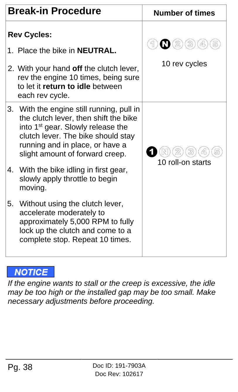
Break-in Procedure Number of times Rev Cycles:
1. Place the bike in NEUTRAL. 2. With your hand off the clutch lever,
rev the engine 10 times, being sure to let it return to idle between each rev cycle.
10 rev cycles
3. With the engine still running, pull in the clutch lever, then shift the bike into 1st gear. Slowly release the clutch lever. The bike should stay running and in place, or have a slight amount of forward creep.
4. With the bike idling in first gear, slowly apply throttle to begin moving.
5. Without using the clutch lever, accelerate moderately to approximately 5,000 RPM to fully lock up the clutch and come to a complete stop. Repeat 10 times.
10 roll-on starts
If the engine wants to stall or the creep is excessive, the idle may be too high or the installed gap may be too small. Make necessary adjustments before proceeding.

Doc ID: 191-7903A Doc Rev: 102617
Pg. 39
6. Without using the clutch lever, start in 2nd gear, then accelerate moderately to approximately 5,000 RPM and come to a complete stop. Repeat 10 times.
10 roll-on starts
7. Place the bike in NEUTRAL and recheck Free Play Gain and adjust the installed gap until the clutch lever is 1/8” (3 mm).
Recheck Free Play Gain and adjust the
installed gap
Your clutch pack will expand with heat, so final adjustment to Free Play Gain should be made when the bike is warm. Remember not to ride without sufficient Free Play Gain.
4 strokes only: It is normal for some clutch debris to be produced during break in. Following break-in, remove and inspect the OE oil filter. Clean or replace it if necessary. Remove and inspect any additional oil screens for clutch debris and clean or replace if necessary.
Do not perform 3rd gear starts with this product. Starting in 3rd gear will burn up the clutch and decrease the performance of this product in a short amount of time.

Pg. 40 Doc ID: 191-7903A Doc Rev: 102617
MAINTENANCE To keep your clutch performing at its best, perform regular maintenance on your bike and clutch.
• Keep up with regular oil changes according to the bike manufacturer’s recommendations. Clutch performance and longevity depend on oil quality.
• Oil recommendations can also be viewed under Tech Tips on our website at www.rekluse.com/support/videos/atv-mc-support-videos.
• Inspect all of your clutch parts for signs of wear or excessive heat, and replace components as necessary. This includes your basket sleeves and dampers. Clutch wear is dependent on the riders use. See the Setup Sheet for additional information.

Doc ID: 191-7903A Doc Rev: 102617
Pg. 41
Maintenance Protocol Maintenance Intervals
Check and verify Free Play Gain Every ride
Inspect all clutch parts for excessive wear or heat. Replace as needed.
Refer to OE service manual
Change oil, inspect and clean oil screen
Refer to OE service manual
• Measuring the clutch pack and/or the EXP disk can help determine if the components need replacing. See the Setup Sheet for the specific clutch pack measurements.
• Maintain adequate Free Play Gain. Check before every ride and adjust if necessary.
• Repeat the break-in procedure anytime you replace the EXP bases, Teflon pads, EXP wedges, or frictions disks. Always soak friction disks or EXP bases in oil for at least 5 minutes before installing.
• Replace friction disks if they measure below specifications listed on the attached Setup Sheet or if the disks are glazed and/or burnt.
• Replace the drive plates if they show signs of excessive heat.
Disk inspection examples When inspecting the clutch pack, the following pictures can be used as a reference. These are best viewed in color by viewing this install document from www.rekluse.com/support. Drive Plates – If the clutch pack is getting high amounts of heat, purple, blue, or black color can be seen on the drive plate teeth. See pictures below. Not all drive plates look the same and may look different than pictured.

Pg. 42 Doc ID: 191-7903A Doc Rev: 102617
Normal Heat High Heat Excessive Heat (Blue) (Black)
Friction Disks – Due to the dark color of the friction material, the friction disks will appear almost black as soon as they are put in oil. During inspection, look for glazing of the friction material. Glazing will appear shiny and feel like glass, even after oil is cleaned from the friction disk. Not all friction disks look the same and may look different than pictured.
Normal Friction Glazed Friction

Doc ID: 191-7903A Doc Rev: 102617
Pg. 43
TROUBLESHOOTING Performance issues If you find yourself constantly adjusting Free Play Gain or adjusting for drag, the clutch disks might be worn. Excessive heat or clutch slip can cause premature clutch failure as well. Once extreme temperatures are reached, irreversible damage will occur. • Inspect all of your clutch parts for signs of wear or excessive
heat, and replace components as necessary. Clutch wear is dependent on the riders use.
• Measuring the clutch pack and/or the EXP disk can help determine if the components need replacing. See the attached Setup Sheet for the specific clutch pack measurements.
Clutch noise Although it is harmless, some bike models may have noise coming from the clutch at low RPM as it engages. Clutch noise is caused by the clutch components vibrating as the clutch engages and can become more audible as the clutch gets hot. Adjusting the installed gap will NOT affect clutch squeal or chatter. For bike models that have noise, here are some recommendations to reduce or eliminate it: • Change the oil: Rekluse recommends that you have fresh,
clean JASO-MA or JASO-MA2 rated oil for best clutch performance. Dirty or old oil can make the clutch more likely to squeal or chatter.
• Some bikes are more prone to clutch squeal and chatter than others. You can convert to from internal to external adjustment to reduce noise if desired.

Pg. 44 Doc ID: 191-7903A Doc Rev: 102617
Locking pin O-ring The RadiusCX comes with an O-ring installed on the locking pin. It acts as a damper between the clutch and the adjustment ring to prevent clutch noise. A missing O-ring will not affect how the clutch functions or damage the internal adjustment ring. An extra O-ring comes in the kit in case you need to replace it.
EXP TUNING OPTIONS Adjusting the engine idle speed to match your engagement setting is important and greatly affects the overall feel of how the EXP disk engages.
You can tune the engagement RPM of the EXP disk by changing the spring configuration. The EXP disk comes set with the recommended “Medium” setting from Rekluse. For other EXP tuning options, see the Setup sheet. To prevent freewheeling and maximize engine braking, set the idle so there is a slight amount of drag while the bike is idling in gear and warmed up. The idle should not be so high as to move the bike forward in gear with the throttle closed. With correct Free Play Gain and the bike in gear, the bike should move forward under slight opening of the throttle. If not, one of the following symptoms is likely: • HIGH IDLE: The bike moves forward with the throttle fully
closed. Solution: reduce idle RPM.
• LOW IDLE: The bike moves forward after engine RPM becomes noticeably higher than idle RPM. Solution: increase idle RPM.

Doc ID: 191-7903A Doc Rev: 102617
Pg. 45
Changing the EXP springs Use the following steps to change the EXP spring configuration. It is NOT necessary to disassemble the EXP halves to change springs!
1. Using a flat-blade screwdriver, push the ¼ turn pin in far enough to clear the opposite side of the EXP to unlock the pin.
2. With the pin still pushed past the base, turn 90° to remove the pin and spring.
3. Remove the remaining 2 pins and springs from the same side of the EXP base.
4. Drop a new spring into the spring slot on the base, then add the ¼ turn pin.
5. Push the turn pin in far enough to clear the base, then turn 90° and release the pin. The pin should sit almost flush with the EXP base.
6. Flip the EXP friction disk over, and repeat on the other side depending on engagement preference.
7. If you need to disassemble the EXP disk, you can watch the video on our website under Tech Tips at www.rekluse.com/support/videos/atv-mc-support-videos.

Pg. 46 Doc ID: 191-7903A Doc Rev: 102617
To maintain even pressure, when using two different color spring sets, install one set of 3 on one side of the EXP and the remaining set of 3 on the other side.
If you disassemble the EXP, the Teflon pads may fall out or be stuck to the ramp surfaces of the EXP bases. Take care to ensure all pads are correctly placed into wedge pockets using gentle pressure to avoid damage to the pad surfaces before reassembling the EXP. Properly seated pads will be secured in place once the EXP is reassembled. Operating the clutch without the pads in place will cause part damage or failure.

Doc ID: 191-7903A Doc Rev: 102617
Pg. 47
BUMP-STARTING: Internally Adjusted FOR INTERNALLY ADJUSTED CLUTCHES ONLY. See the “BUMP-STARTING: External” section in Appendix A for instructions on how to bump start with the external adjustment method.
1. Remove the clutch cover.
2. Pull the clutch lever to lift the pressure plate, and secure the lever to the handlebar using the Velcro strap provided.
3. Unlock the red locking pin, and turn the adjuster ring clockwise until it bottoms out in the center hub.
4. Lock the locking pin to secure the ring in place.
5. Release the clutch lever, and use the perch adjuster to remove cable tension until you have lever free play (slack).
6. Install the clutch cover and bump-start the bike. The clutch will function like a manual clutch at this point, but the clutch will not be fully over-rideable at high RPM.
It is not recommended to ride any further than necessary with the clutch’s installed gap collapsed.
7. When able, reset the installed gap using either the internal or external adjustment method before riding again.

Pg. 48 Doc ID: 191-7903A Doc Rev: 102617
CLUTCH LEVER OPTIMIZATION If your bike model is not equipped with a perch adjuster bolt (as seen below), you may purchase, as an option, a Rekluse Adjustable Reach Lever.
Adding this accessory maximizes your clutch lever feel during operation. If you opt to continue installation without the Rekluse Adjustable Reach Lever and your bike is not equipped with an OE perch adjuster bolt, continue with the sections on “Set the installed gap internally,” or Appendix A “Set the installed gap externally.”
Optimization with OE Perch Adjuster Kits for Kits for Honda CRF 450 and CRF 250 include a new perch adjuster bolt. Replace your OE perch adjuster bolt with the one included in your kit. These bolts will not be used on the CRF450RX. Set the clutch lever to the desired reach point while maintaining clutch lever slack.
• Turning your adjuster bolt farther in will bring the lever closer to the bar and allow for a closer reach point.
• Backing your adjuster bolt farther out will push the lever farther from the bar and allow for a further reach point.

Doc ID: 191-7903A Doc Rev: 102617
Pg. 49
Optimization with Rekluse Adjustable Reach Lever Set the clutch lever to the desired reach point while maintaining clutch lever slack. • Turing your adjuster bolt farther in will push the lever farther
from the bar and allow for a further reach point.
• Backing your adjuster bolt farther out will bring the lever closer to the bar and allow for a closer reach point.

Pg. 50 Doc ID: 191-7903A Doc Rev: 102617
APPENDIX A Set the installed gap externally The adjustment ring comes in the proper position for external adjustment. No adjustment is needed.
If you are switching from internal adjustment to external adjustment, turn the ring clockwise until it bottoms out in the hub.
1. Reinstall the OE throw-out assembly (throw-out, bearing, and washer). If the washer is missing, check to see if it is stuck to the underside of the pressure plate.
2. Reinstall the pressure plate, followed by the pressure plate springs, screw sleeves, and bolts.
Do not reuse the OE springs or bolts. They will cause interference with the clutch cover!
2017 or newer Honda 450 owners: The throw-out is one piece, with no washer or bearing.

Doc ID: 191-7903A Doc Rev: 102617
Pg. 51
Be sure to alternate springs if you are using two different color springs to keep even pressure on the clutch. Heavier springs are available for purchase from Rekluse for high horse-power applications. 3. Using a torque wrench, tighten the pressure plate bolts to 9 ft-lb
(12-N-m). 4. Reinstall the OE cover gasket.
5. Place the Rekluse clutch cover onto the bike. Reinstall the OE
bolts into the clutch cover. Be sure to return the bolts in the same location they were removed.
Failure to install the OE clutch cover bolts back in their proper location can result in damage to your motorcycle.
6. If your bike has an OE oil fill plug and/or an engine inspection
plug, transfer the plugs to the new Rekluse clutch cover. Tighten the plugs.
7. Stand the bike upright.

Pg. 52 Doc ID: 191-7903A Doc Rev: 102617
8. Use a wrench to loosen the jam nut and completely collapse the in-line cable adjuster allowing for plenty of clutch cable and lever slack.
9. At the in-line cable adjuster, tighten the clutch cable tension
to the point where there is no lever freeplay (the clutch lever is tight against its perch). At this point, there should be no cable slack.
10. Expand the in-line cable adjuster housing 5 turns to lift pressure plate. This is not your final setting. It is your starting point for setting the installed gap. This will vary by bike.
CLUTCH LEVER TIGHT AGAINST PERCH (ADJUST SLACK INTO CABLE)

Doc ID: 191-7903A Doc Rev: 102617
Pg. 53
11. To set the final install gap, check Free Play Gain. Refer to the to the section titled “CHECK FREE PLAY GAIN” on page 28 for the directions.
12. When Free Play Gain is optimal, continue to the section titled, “Step 3: Break in the new clutch,” on page 37.
If Free Play Gain is not optimal, the installed gap needs to be adjusted.
Adjust the installed gap by adjusting the cable at the clutch lever perch or in-line cable to achieve the correct amount. The installed gap should be fine-tuned in small increments and then recheck Free Play Gain.
Refer to the table below to set the proper installed gap based on your Free Play Gain.
Adjust Installed Gap Externally at the Perch
Symptom Reason Solution
• Clutch lever moves in too far (too much Free Play Gain)
• Clutch has excessive drag or stalls
• It is difficult to fully
override the clutch with the lever
Installed gap is too small
Tighten the cable; increase the length of the in-line cable adjuster housing and/or the lever perch adjuster (extend the adjusters) until the correct amount of Free Play Gain is achieved. Recheck Free Play Gain.

Pg. 54 Doc ID: 191-7903A Doc Rev: 102617
• Clutch lever only
moves slightly or does not move at all (too little Free Play Gain)
• Clutch slips
• Bike seems to lose power
Installed gap is too large
Reduce the length of the cable housing (collapse the adjusters) until the correct amount of freeplay gain is achieved. Recheck Free Play Gain.
BUMP-STARTING: Externally Adjusted FOR EXTERNALLY-ADJUSTED CLUTCHES ONLY. See the “BUMP-STARTING: Internally Adjusted” section for instructions on how to bump start with the internal adjustment method.
1. Use the perch adjuster or in-line cable adjuster to remove cable tension until you have lever free play (slack).
2. Bump-start the bike. The clutch will function like a manual clutch at this point, but the clutch will not be fully over-rideable at high RPM.
It is not recommended to ride any further than necessary with the clutch’s installed gap collapsed.
3. Once the vehicle is running, readjust the cable tension to properly set the installed gap using Free Play Gain.

Doc ID: 191-7903A Doc Rev: 102617
Pg. 55
NEED ADDITIONAL HELP?
Website www.rekluse.com/support
Frequently asked questions www.rekluse.com/faq
Support Videos www.rekluse.com/support/videos Phone (208) 426-0659 Technical Support Contact Technical Support for questions related to product installation, tuning, and performance.
Technical Support hours: Monday thru Friday: 8:00 a.m. - 5:00 p.m. Mountain Time zone Email: [email protected] Customer Service Contact Customer Service for additional product information, orders, and returns.
Customer Service hours: Monday thru Friday: 8:00 a.m. - 5:00 p.m. Mountain Time zone Email: [email protected]