INSTALLATION & USER’S - Rekluse
24
©2018 Rekluse Motor Sports Rekluse Motor Sports, Inc. customerservice@rekluse.com INSTALLATION & USER’S GUIDE RadiusX Clutch for Cable Actuated Bikes and ATVs Doc ID: 191-6300A Revision: 040919
Transcript of INSTALLATION & USER’S - Rekluse

©2018 Rekluse Motor Sports Rekluse Motor Sports, Inc.
INSTALLATION & USER’S
GUIDE
RadiusX Clutch for Cable Actuated Bikes and ATVs
Doc ID: 191-6300A Revision: 040919

Pg. 2 Doc ID: 191-6300A
Doc Rev: 040919
TABLE OF CONTENTS
OVERVIEW ........................................................................... 2
INSTALLATION TIPS ............................................................ 3
TOOLS NEEDED ................................................................... 4
INCLUDED PARTS ............................................................... 4
DISASSEMBLE THE CLUTCH ............................................. 4
CLUTCH PACK INSTALLATION ........................................... 7
Notes for clutch pack installation ....................................... 7
Install Clutch Pack .............................................................. 9
SET THE INSTALLED GAP ................................................ 12
CHECK FREE PLAY GAin .................................................. 12
Learn how to check Free Play Gain ................................. 13
Two Ways to Check for Free Play Gain ........................... 13
The Rubber Band Method ................................................ 13
The Hand Method ............................................................ 15
ADJUST THE INSTALLED GAP ......................................... 16
BREAK-IN THE NEW CLUTCH .......................................... 18
CLUTCH LEVER OPTIMIZATION ....................................... 20
Optimization with OE Perch Adjuster ............................... 20
Optimization with Rekluse Adjustable Reach Lever ........ 21
MAINTENANCE ................................................................... 21
Clutch wear ...................................................................... 21
Clutch parts ...................................................................... 22
Basket .............................................................................. 22
Disk inspection examples ................................................ 23
NEED ADDITIONAL HELP? ................................................ 24
OVERVIEW
This kit replaces many of the OE (Original Equipment) or “stock” clutch parts. These parts are designed specifically for your motorcycle to ensure optimal performance. The following is a summary of what is replaced:

Doc ID: 191-6300A
Doc Rev: 040919
Pg. 3
• This kit will replace all the OE friction disks and drive plates with a Rekluse thin friction EXP clutch pack.
• The OE pressure plate springs are replaced with high quality Rekluse springs.
INSTALLATION TIPS
• Read the separate included Safety Information document before operating the vehicle with the product installed.
• Read this entire document before performing any steps.
• If you install this product for a customer or another person, instruct them to read the Safety Information document and the Installation and User Guide before operating the vehicle with the product.
• Protect eyes and skin – wear safety glasses and work gloves.
• Lay the motorcycle on its left side when replacing the clutch. This makes working on the clutch easier and eliminates the need to drain the oil. Catch any fuel that may drain from the bike.
• Drain the oil from an ATV before installing the clutch.
• Use the torque specifications found in your OE service manual.
• For optimal clutch performance Rekluse recommends using fresh, clean oil that meets JASO-MA oil rating requirements. Rekluse offers Factory Formulated Oil™ developed specifically for Rekluse products. Rekluse Factory Formulated Oil is a perfect complement to any OEM or aftermarket wet clutch. Visit www.rekluse.com to learn more.
• This clutch pack is not legal to race with in the AMA Limited or Stock class.

Pg. 4 Doc ID: 191-6300A
Doc Rev: 040919
TOOLS NEEDED
INCLUDED PARTS
The parts included in the kit depend on the bike or ATV model. See the Setup Sheet at the back of this manual for a list of included parts and illustration.
You can also visit our website at www.rekluse.com/support for a full parts fiche illustration and part numbers.
DISASSEMBLE THE CLUTCH
1. Soak the Rekluse friction disks in new oil for at least 5 minutes. Make sure the friction disks are coated on both sides.
10 mm socket
8 mm socket Metric
Wrench Torque Wrench
Pick Fluid Catch Container
4 mm Hex
key
4 mm

Doc ID: 191-6300A
Doc Rev: 040919
Pg. 5
2. If applicable, turn the fuel petcock to “OFF.”
3. For bikes, lay the bike on its left side. Catch any fluids that might drain into a suitable container. For ATVs, drain the oil into a suitable container before disassembly.
4. Remove the OE clutch access cover. Set aside. It will be
reused. 5. Remove the OE pressure plate bolts, springs, and
pressure plate.

Pg. 6 Doc ID: 191-6300A
Doc Rev: 040919
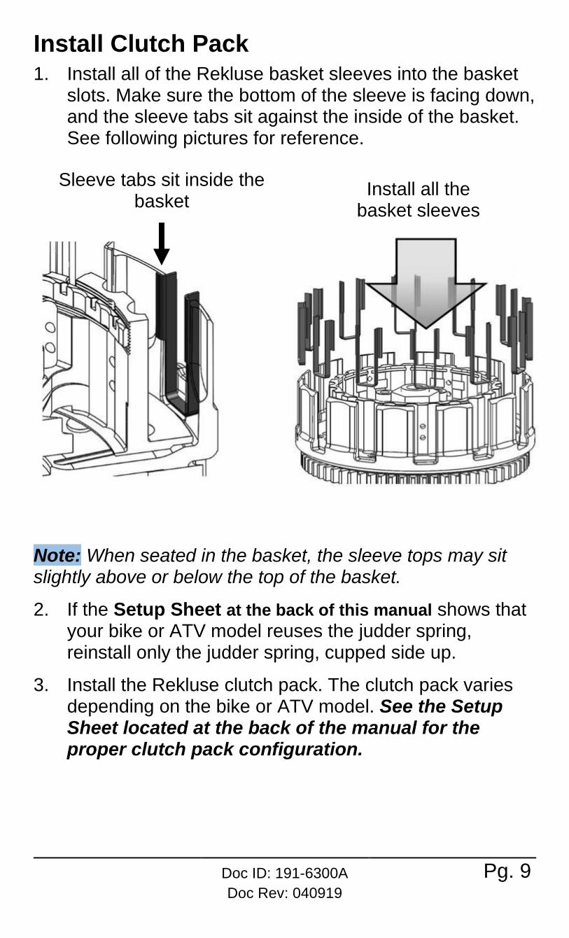
Note: Throw-out washers can stick to the back of the pressure plate. Be sure to reinstall any throw-out washers back onto the throw-out. 6. Remove the clutch pack.
Note: Some models have a clutch boss spring located in the bottom of the OE friction pack. This consists of a spring, seat and narrow friction. If your model is equipped with these parts, remove them and set the spring aside. Only some models will reuse the spring. Refer to the Setup Sheet at the
back of this manual to see if your model reuses these parts.

Doc ID: 191-6300A
Doc Rev: 040919
Pg. 7
CLUTCH PACK INSTALLATION
Notes for clutch pack installation
• Some friction disks are marked with a small colored dot. This mark is used for processing and can be ignored.
• Some OE baskets have “half slots” at the top of the basket tangs. Rekluse products require the entire clutch pack be installed into the MAIN (deeper) basket slots. Do not use the “half slots.” See the following picture for reference.
• Inspect the clutch basket for damper and/or spring play. Inspect the clutch basket for notching. Do not install sleeves or use product with a notched basket. Notched basket tang faces can cause the sleeves to break. Do not use baskets that have been filed, machined, or modified on the tangs. Replace basket if necessary.
Pg. 8 Doc ID: 191-6300A
Doc Rev: 040919
Failure to inspect the basket and replace if necessary could result in death, serious injury, and/or property damage.
Note: If the basket is notched or
worn, Rekluse recommends
replacing it with a Rekluse Billet
Clutch Basket (available for most
models).
• Inspect your OE center hub and pressure plate flanges for
excess wear. If wear is visible use a drop gauge to verify
that the wear across the flange does not exceed .005”
(.12mm).
Doc ID: 191-6300A
Doc Rev: 040919
Pg. 9
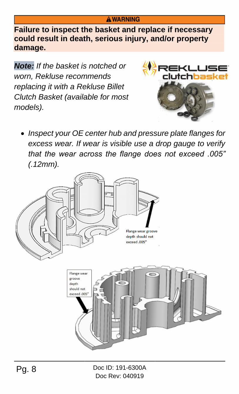
Install Clutch Pack 1. Install all of the Rekluse basket sleeves into the basket
slots. Make sure the bottom of the sleeve is facing down, and the sleeve tabs sit against the inside of the basket. See following pictures for reference.
Note: When seated in the basket, the sleeve tops may sit slightly above or below the top of the basket.
2. If the Setup Sheet at the back of this manual shows that your bike or ATV model reuses the judder spring, reinstall only the judder spring, cupped side up.
3. Install the Rekluse clutch pack. The clutch pack varies depending on the bike or ATV model. See the Setup Sheet located at the back of the manual for the proper clutch pack configuration.
Sleeve tabs sit inside the basket
Install all the basket sleeves
Pg. 10 Doc ID: 191-6300A
Doc Rev: 040919
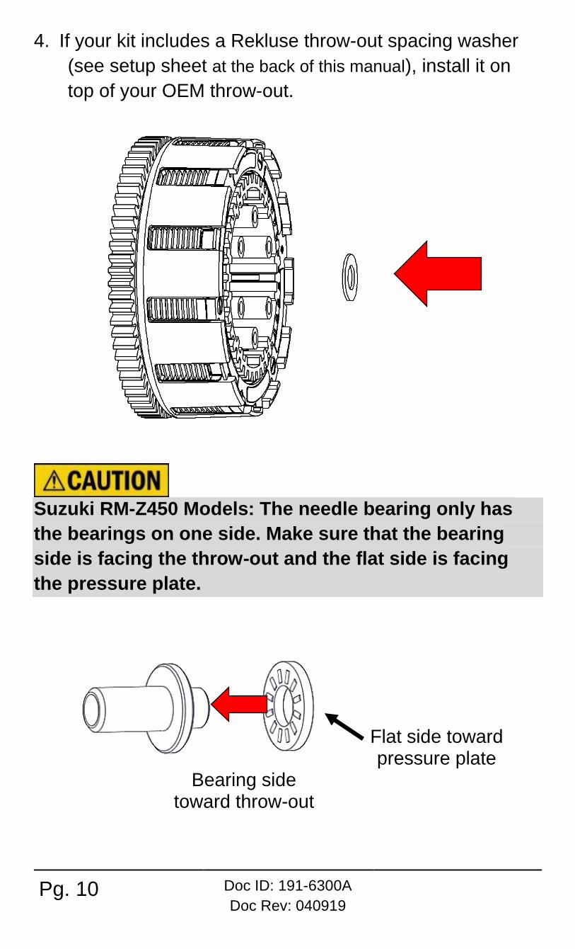
4. If your kit includes a Rekluse throw-out spacing washer
(see setup sheet at the back of this manual), install it on
top of your OEM throw-out.
Suzuki RM-Z450 Models: The needle bearing only has
the bearings on one side. Make sure that the bearing
side is facing the throw-out and the flat side is facing
the pressure plate.
Flat side toward pressure plate
Bearing side toward throw-out

Doc ID: 191-6300A
Doc Rev: 040919
Pg. 11
5. Reinstall the pressure plate, then install the Rekluse pressure plate springs and bolts.
Note: DRZ 400, KLX 400, KX 500 bike models:
If your kit includes Rekluse screw sleeves or spring bolts, install them in place of the OE components. DRZ 400 and KLX 400 models will utilize the supplied Rekluse screw sleeves and OE bolts, and KX 500 models will utilize supplied Rekluse screw sleeves and Rekluse bolts.
Rekluse springs
OE Bolts
Rekluse springs
Rekluse Bolts
Rekluse Screw Sleeves

Pg. 12 Doc ID: 191-6300A
Doc Rev: 040919
Note: If the clutch kit includes 2 different colors of springs, be sure to alternate the springs. This will ensure even pressure on the clutch.
6. Torque the pressure plate bolts in small increments in a star pattern to OE specifications.
7. Install the clutch cover gasket based on your bike or ATV model.
8. Reinstall the clutch cover, then reinstall the cover bolts.
9. Lightly tightening the cover bolts in a star pattern. Torque the bolts in small increments in a star pattern before tightening the bolts to OE specifications.
SET THE INSTALLED GAP
1. The clutch lever should be tight against the perch. If not, adjust the cable so that the lever is tight against the perch.
2. Turn the cable and/or perch adjuster 3-5 turns tighter. Tightening beyond the initial perch adjustment creates the installed gap.
3. Continue the installation by checking for Free Play Gain.
CHECK FREE PLAY GAIN
The proper installed gap is verified by checking Free Play Gain.
Correct Free Play Gain = Correct installed gap
Setup, break-in, and rechecking the installed gap is CRUCIAL. Failure to properly maintain your installed gap can result in premature wear or failure of your clutch.
Failure to check and verify Free Play Gain can cause
failure or damage to this product. Setting the correct
installed gap is critical for clutch performance.

Doc ID: 191-6300A
Doc Rev: 040919
Pg. 13
Learn how to check Free Play Gain If you are familiar with checking Free Play Gain, check for Free Play Gain then skip to the “Adjust the Installed Gap” section.
If Free Play Gain is new to you, follow the instructions below to help you learn this important step. You can also view the video entitled “How to Check Free Play Gain” on our website at www.rekluse.com/support/videos.
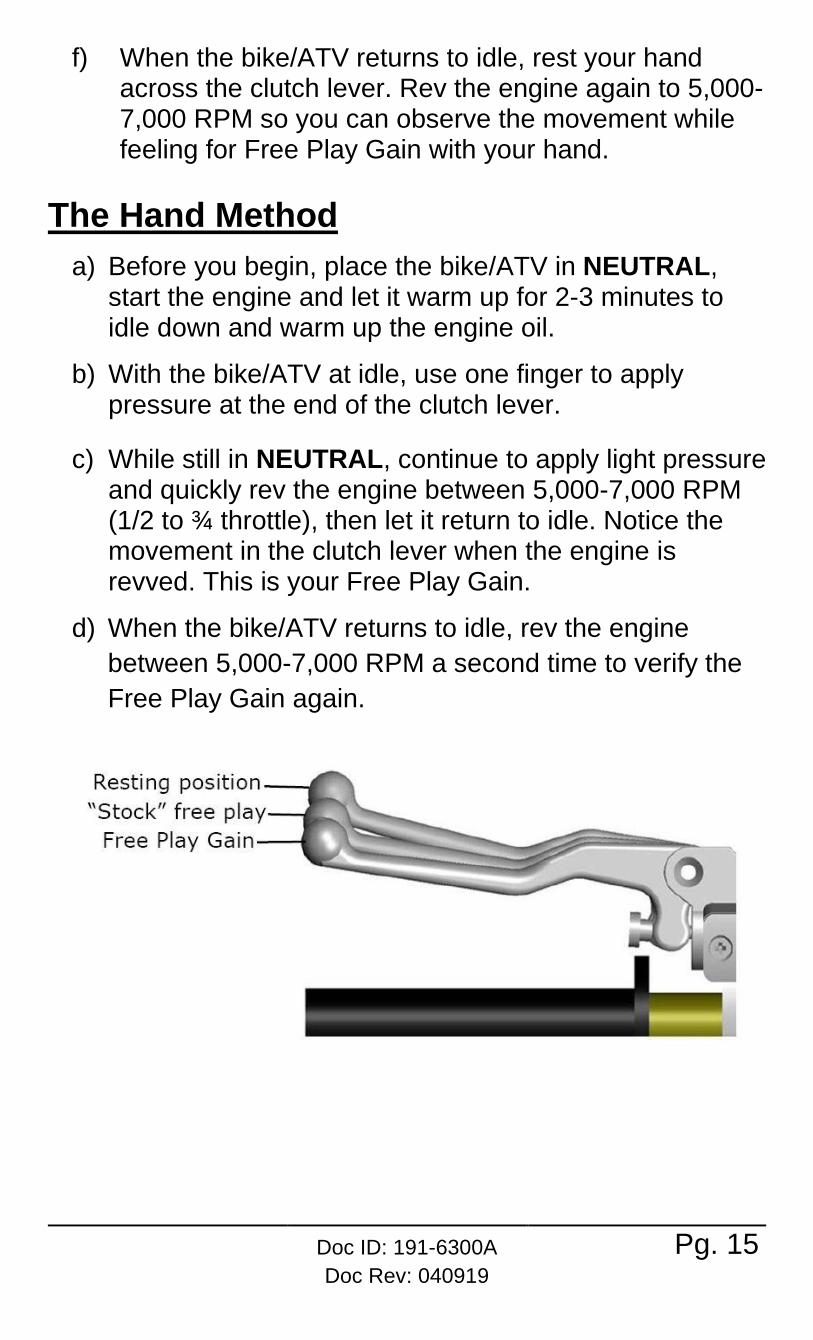
Optimal Free Play Gain yields 1/8”-1/4” (3 mm-6 mm) of clutch lever movement, measured at the ball end of the lever. This measurement at the lever correlates to achieving the ideal installed gap.
Two Ways to Check for Free Play Gain There are two ways to check for Free Play Gain. One way uses the rubber band Rekluse includes in the clutch kit, and one uses your hand. You can use either method to check for Free Play Gain.
The Rubber Band Method Use the rubber band method for the initial set up. It can also be used before each ride until you feel comfortable checking the Free Play Gain using the hand method.
BEFORE YOU BEGIN, verify that the bike or vehicle is in NEUTRAL before checking Free Play Gain. Failure to do so may result in the bike or vehicle lurching forward, and loss of control and/or injury may result. A Rekluse auto-clutch can make your motorcycle or vehicle appear to be in neutral when in gear, even when the engine is running and clutch lever released. Motorcycles or vehicle equipped with a Rekluse auto-clutch can move suddenly and unexpectedly and cause riders to lose control. To avoid death, serious injury,
Pg. 14 Doc ID: 191-6300A
Doc Rev: 040919
and/or property damage, always sit on the motorcycle or ATV to start it.
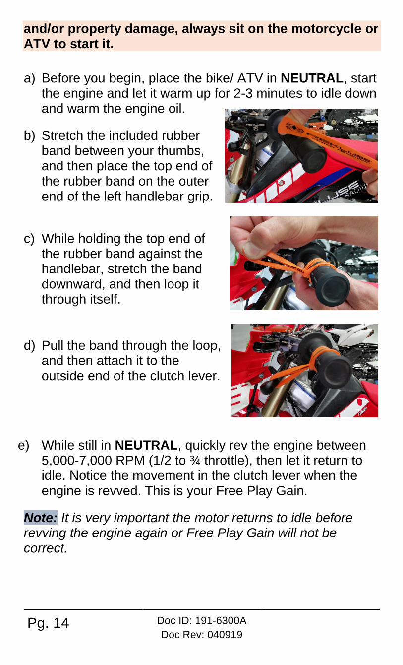
a) Before you begin, place the bike/ ATV in NEUTRAL, start the engine and let it warm up for 2-3 minutes to idle down and warm the engine oil.
b) Stretch the included rubber band between your thumbs, and then place the top end of the rubber band on the outer end of the left handlebar grip.
c) While holding the top end of the rubber band against the handlebar, stretch the band downward, and then loop it through itself.
d) Pull the band through the loop, and then attach it to the outside end of the clutch lever.
e) While still in NEUTRAL, quickly rev the engine between 5,000-7,000 RPM (1/2 to ¾ throttle), then let it return to idle. Notice the movement in the clutch lever when the engine is revved. This is your Free Play Gain.
Note: It is very important the motor returns to idle before revving the engine again or Free Play Gain will not be correct.
Doc ID: 191-6300A
Doc Rev: 040919
Pg. 15
f) When the bike/ATV returns to idle, rest your hand across the clutch lever. Rev the engine again to 5,000-7,000 RPM so you can observe the movement while feeling for Free Play Gain with your hand.
The Hand Method
a) Before you begin, place the bike/ATV in NEUTRAL, start the engine and let it warm up for 2-3 minutes to idle down and warm up the engine oil.
b) With the bike/ATV at idle, use one finger to apply pressure at the end of the clutch lever.
c) While still in NEUTRAL, continue to apply light pressure and quickly rev the engine between 5,000-7,000 RPM (1/2 to ¾ throttle), then let it return to idle. Notice the movement in the clutch lever when the engine is revved. This is your Free Play Gain.
d) When the bike/ATV returns to idle, rev the engine
between 5,000-7,000 RPM a second time to verify the
Free Play Gain again.

Pg. 16 Doc ID: 191-6300A
Doc Rev: 040919
ADJUST THE INSTALLED GAP
After checking for Free Play Gain, you may need to adjust the installed gap. If Free Play Gain is optimal, continue to “Break In The New Clutch”. If Free Play Gain is not optimal, the installed gap needs to be adjusted.
The installed gap should be fine-tuned in small increments and then recheck Free Play Gain. Refer to the table below to set the proper installed gap based on your Free Play Gain.
Notes: If you are unable to obtain the correct Free Play Gain or you are nearly out of cable adjustment after performing the adjustment, your cable may be worn or stretched from wear or use. If this is the case, purchasing a new cable should provide the necessary performance.
Adjust the Installed Gap
Symptom Reason Solution
• Clutch lever moves in too far (too much Free Play Gain)
• Clutch has excessive drag or stalls
• It is difficult to fully override the clutch with the lever
Installed gap is too small
Tighten the cable: increase the length of the in-line cable adjuster housing until the correct amount of Free Play Gain is achieved. Recheck Free Play Gain.

Doc ID: 191-6300A
Doc Rev: 040919
Pg. 17
• Clutch lever only moves slightly or does not move at all (too little Free Play Gain)
• Clutch slips
• Bike/ATV seems to lose power
Installed gap is too large
Loosen the cable: Reduce the length of the cable housing (collapse the adjusters) until the correct amount of Free Play Gain is achieved. Recheck Free Play Gain.

Pg. 18 Doc ID: 191-6300A
Doc Rev: 040919
BREAK-IN THE NEW CLUTCH
Once you install your new clutch, it is important to break it in. A series of roll-on starts are used to break in the clutch. Follow these procedures for breaking in your clutch and any time new friction disks, EXP bases, Teflon pads, or wedges are installed.
Failure to follow the break-in procedure and oil screen inspection process could cause motor oil delivery failure, which can result in motor failure, serious injury, or death.
Break-in Procedure Number of times
Rev Cycles:
1. Place the bike or ATV in NEUTRAL.
2. With your hand off the clutch
lever, rev the engine 10 times, being sure to let it return to idle between each rev cycle.
10 rev cycles
3. With the engine still running, pull in the clutch lever, then click the bike/ATV into 1st gear. Slowly release the clutch lever. The bike/ATV should stay in place or have a slight amount of forward creep.
4. With the bike/ATV idling in first gear, slowly apply throttle to begin moving.
Continued on next page

Doc ID: 191-6300A
Doc Rev: 040919
Pg. 19
5. Without using the clutch lever, accelerate moderately to approximately 5,000 RPM to fully lock up the clutch and come to a complete stop. Repeat 10 times.
Note: If the engine wants to stall or the creep is excessive, the idle may be too high or the installed gap may be too small. Make necessary adjustments before proceeding.
10 roll-on starts
6. Without using the clutch lever, start in 2nd gear, then accelerate moderately to approximately 5,000 RPM and come to a complete stop. Repeat 10 times.
10 roll-on starts
7. Place the bike or ATV in NEUTRAL and recheck Free Play Gain.
8. Continue to step 4 to adjust the installed gap until the Free Play Gain of the clutch lever is 1/8” to ¼” (3 mm-6 mm).
Recheck Free Play
Gain and adjust the
installed gap
Note: Your clutch pack will expand with heat, so final adjustment to Free Play Gain should be made when the bike or ATV is warm. Remember not to ride without sufficient Free Play Gain.
Do not perform 3rd gear starts with this product. Starting in 3rd gear will burn up the clutch and decrease the performance of this product in a short amount of time.

Pg. 20 Doc ID: 191-6300A
Doc Rev: 040919
CLUTCH LEVER OPTIMIZATION
If your bike model is not equipped with a perch adjuster bolt,
you may purchase, as an option, a Rekluse Adjustable
Reach Lever.
Optimization with OE Perch Adjuster Kits for Honda CRF 450 and CRF 250 include a new perch
adjuster bolt. Replace your OE perch adjuster bolt with the
one included in your kit. These bolts will not be used on the
CRF450RX.
Kits for Yamaha YZ450F and YZ250F include a new perch
adjuster bolt. Replace your OE perch adjuster bolt with the
one included in your kit. These bolts will not be used on the
YZ450FX and YZ250FX.
Adjust the lever:
• Set the clutch lever to the desired reach point while
maintaining clutch lever slack.
• Turning your adjuster bolt farther in will bring the lever closer to the bar and allow for a closer reach point.
• Backing your adjuster bolt farther out will push the lever farther from the bar and allow for a further reach point.

Doc ID: 191-6300A
Doc Rev: 040919
Pg. 21
Optimization with Rekluse Adjustable Reach Lever Set the clutch lever to the desired reach point while
maintaining clutch lever slack.
• Turning your adjuster bolt farther in will push the lever farther from the bar and allow for a further reach point.
• Backing your adjuster bolt farther out will bring the lever closer to the bar and allow for a closer reach point.
MAINTENANCE
To keep your clutch performing at its best, perform regular maintenance on your bike or ATV and clutch.
Clutch wear Rekluse clutches are built using high quality materials but do wear based on the rider’s use, type of terrain, and natural wear and tear. To keep your clutch performing at its best, perform regular maintenance on your bike/ATV and clutch based on your riding style.
• Maintain adequate Free Play Gain. Check before every ride and adjust as necessary.
• Repeat the break-in procedure anytime you replace any components of the EXP disk or frictions disks. Always soak new friction disks in fresh oil before installing.
Pg. 22 Doc ID: 191-6300A
Doc Rev: 040919
Clutch parts • Inspect all of your clutch parts at regular intervals for
signs of wear or excessive heat, and replace
components as necessary. Rekluse recommends
inspecting after the first 10 hours of use, then every 20
hours after that.
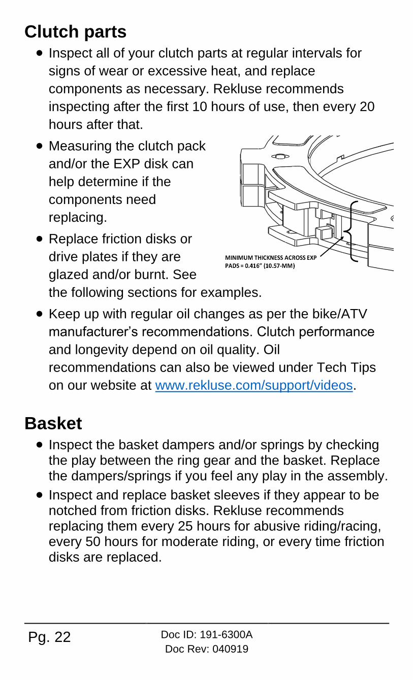
• Measuring the clutch pack
and/or the EXP disk can
help determine if the
components need
replacing.
• Replace friction disks or
drive plates if they are
glazed and/or burnt. See
the following sections for examples.
• Keep up with regular oil changes as per the bike/ATV
manufacturer’s recommendations. Clutch performance
and longevity depend on oil quality. Oil
recommendations can also be viewed under Tech Tips
on our website at www.rekluse.com/support/videos.
Basket • Inspect the basket dampers and/or springs by checking
the play between the ring gear and the basket. Replace the dampers/springs if you feel any play in the assembly.
• Inspect and replace basket sleeves if they appear to be notched from friction disks. Rekluse recommends replacing them every 25 hours for abusive riding/racing, every 50 hours for moderate riding, or every time friction disks are replaced.

Doc ID: 191-6300A
Doc Rev: 040919
Pg. 23
Disk inspection examples When inspecting the clutch pack, the following pictures can be used as a reference. These are best viewed in color by viewing this install document at www.rekluse.com/support.
Drive Plates – If the clutch pack is getting high amounts
of heat, purple, blue, or black color can be seen on the drive plate teeth. See pictures below. Not all drive plates look the same and may look different than pictured.
Normal Heat High Heat Excessive Heat (Blue) (Black)
Friction Disks – Due to the dark color of the friction
material, the friction disks will appear almost black as soon as they are put in oil. During inspection, look for glazing of the friction material. Glazing will appear shiny and feel like glass, even after oil is cleaned from the friction disk. Not all friction disks look the same and may look different than pictured.
Normal Friction
Glazed Friction

Pg. 24 Doc ID: 191-6300A
Doc Rev: 040919
NEED ADDITIONAL HELP?
Website
www.rekluse.com/support
Frequently asked questions
www.rekluse.com/faq
Support Videos
www.rekluse.com/support/videos
Phone
(208) 426-0659
Technical Support
Contact Technical Support for questions related to product installation, tuning, and performance.
Hours: Monday thru Friday: 8:00 a.m. - 5:00 p.m. Mountain Time zone
Email: [email protected]
Customer Service
Contact Customer Service for additional product information, orders, and returns.
Hours: Monday thru Friday: 8:00 a.m. - 5:00 p.m. Mountain Time zone
Email: [email protected]