Steering Geometry
23
STEERING CONTENTS: 1 STEERING GEOMETRY 2 STEERING SYSTEM 3 FRONT WHEEL DRIVE 4 REAR WHEEL DRIVE 5 STEERING MECHANISM
description
Automobile is fragmentary without the steering system as it gives the vehicle a directional stability. Steering enables the driver to easily maneuver the vehicle according to the path. It doesn’t mean that automotive, when developed, included steering mechanism. So, how the steering wheel which we see on today’s car was invented? The automotive freaks, during those days, got the idea of steer the vehicle from boats which used tilters that helped them to turn left or right. The idea was implemented on automobiles too, but didn’t last longer as it required more effort and the steering ability was almost poor. The ultimate discovery of the steering wheel was seen in the Panhard model which was tested in the Paris-Rouen race. This innovation was then seen in every car model that followed and as such the round steering wheel became important and compulsory element of the car.
Transcript of Steering Geometry

STEERINGCONTENTS:
1 STEERING GEOMETRY2 STEERING SYSTEM3 FRONT WHEEL DRIVE4 REAR WHEEL DRIVE5 STEERING MECHANISM

Front and Rear Wheel Drive

Manual Steering
Rack & Pinion housing of a manual steering system.
Yoke plug is used to support the rack bar.
Steering gear is a constant gear ratio type. The pinion gear is supported by the two upper and lower ball bearings

Front Wheel Drive:
In this type of drive, front wheel of the vehicle is a driven wheel; that means the power from the engine is transmit
As the engine and driven wheel is located on the same side of the vehicle, there is no need for a propeller shaft in between the engines and wheelsted to this wheel.
There are three types of Front wheel Drive layout:
1. Front mid engine Front wheel drive: In this type of arrangement, the engine is mounted longitudinally behind the wheels and transmission and the differential is located at the front of the vehicle
2. Front engine Front wheel drive (Longitudinal mounted engine): In this type of arrangement, the engine is mounted longitudinally in front of the front wheels and the engine is located ahead of the transmission
3. Front engine Front wheel drive (Transversely mounted engine): In this type of arrangement, the engine is mounted transversely and the transmission is located below the engine crankshaft

Rear Wheel Drive Layout:
In this type of drive the engine is placed at the front and the power produced by engine is transmitted to the rear wheel through transmission, propeller shaft and axle.
There are four types of Rear wheel layout:
Front Mid engine Rear wheel drive: In this type of layout, the engine is mounted at the front mid and the power is transmitted to the rear wheel
Rear Mid engine Rear wheel drive:In this type of layout, the engine is mounted at the rear mid and the power is transmitted to the rear wheel
Front engine Rear wheel drive: In this type of layout, the engine is mounted at the front of the vehicle and the power is transmitted to the rear wheel.
Rear engine rear wheel drive:In this type of layout, the engine is mounted at the rear of the vehicle and the power is transmitted to the rear wheel.

Steering Geometry
Camber: Caster:
The inward or outward tilt of a wheel from the vertical, when viewed from the front of the vehicle, is called as camber
The tops of wheels of a car, tilt inward when the camber is negative and outward when it is positive
The camber is measured in degrees the wheel suspension is set to
provide slight outward tilt; means positive camber
Any camber, either positive or negative, can cause uneven and rapid tire wear
The caster is defined as a tilt of the steering axis towards the front or rear of the vehicle. If the tilt is towards the front, the wheel has negative caster and the tilt is towards the rear, the wheel has positive caster.
caster is provided in vehicle because of :
To maintain directional stability and control.
To reduce steering effort. To increase steering return
ability

CASTER AND CAMBER:

TOE AND INCLINATION
Toe:Steering-axis inclination :
Toe is the measurement of how much the wheels point in or out from the straight-ahead positionThe measurement of toe is to be done in millimeters, inches or degrees.
the wheels point inward is toe in, at this time toe is positive
the wheels point outward is toe-out, at this time toe is negative.
It is defined as the inclination of the ball joint axis from the vertical. SAI is not adjustable. It would change only; if the wheel spindle or steering knuckle is bent
SAI helps the straight ahead recovery and providing directional stability

TOE AND SAI:


Scrub radius or Steering offset:
1. It is the distance between the steering axis and the tire contact area center line at their intersection with the road surface
2. If king pin inclination center line and wheel center line meets on the same point, it is called zero scrub radius
3. If king pin inclination center line is outside from the wheel center line, it is called negative scrub radius
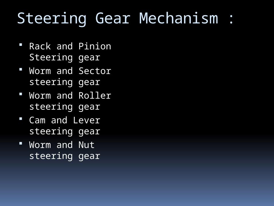
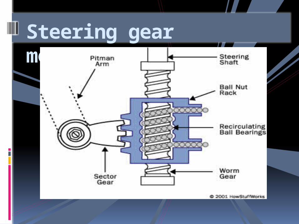
Steering Gear Mechanism :
Rack and Pinion Steering gear
Worm and Sector steering gear
Worm and Roller steering gear
Cam and Lever steering gear
Worm and Nut steering gear


New Technologies and Innovations in the Steering System:
Many new innovations in steering system are available today that gives best possible directional stability to the cars with extreme comfort levels. Some of the improvements include; 4-wheel steering which assists in steering all the four wheels of the car. This helps in maneuvering the car at high speeds. Some of the cars today, also include a system known as speed sensitive steering, which uses a concept that during high speed steering requirements are less and as such the power assistance is reduced. It is increased during low speeds as more steering effort is needed. Future developments in the steering system are being done and experts have come up with an idea of steer-by-wire mechanism in which the steering will be achieved completely using electronics. The main aim of the system, is to eliminate the complex system of linkages and joints giving more space for engine and interior designing aspects.


Kingpin (automotive part)
The kingpin is set at an angle relative to the true vertical line, as viewed from the front or back of the vehicle. This is the kingpin inclination or KPI (also called steering axis inclination, or SAI).SAI is non-adjustable, since it would change only if the wheel spindle or steering knuckles are bent.

Ackerman Steering Geometry
The Ackerman Steering Principle defines the geometry that is applied to all vehicles (two or four wheel drive) to enable the correct turning angle of the steering wheels to be generated when negotiating a corner or a curve.
The intention of Ackermann geometry is to avoid the need for tyres to slip sideways when following the path around a curve
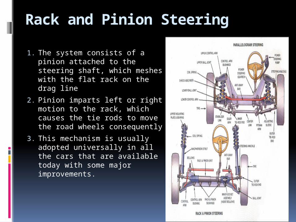
Rack and Pinion Steering
1. The system consists of a pinion attached to the steering shaft, which meshes with the flat rack on the drag line
2. Pinion imparts left or right motion to the rack, which causes the tie rods to move the road wheels consequently
3. This mechanism is usually adopted universally in all the cars that are available today with some major improvements.
Steering gear mechanism

steering gear mechanism
Worm and Sector steering gear Worm and Roller steering gear
In this type of steering mechanism, worm is connected at the end of steering shaft and sector is mounted on a sector shaft
The sector looks like a ball and worm looks like a gear.
The teeth of the worm mesh with the teeth of the sector
To provide free play, worm is mounted on a bearing. It is also known as “Pitman arm shaft
Worm and roller is similar to the worm and sector type of steering mechanism
A toothed roller is mounted on a roller shaft and worm gear is mounted on a steering shaft
Gear tooth of worm gear meshes with that of the roller and motion is transmitted.
. This mechanism has low friction compared to Worm and Sector mechanism and is widely used on American passenger cars.

Steering Gear Mechanism
Cam and lever is similar to the worm and sector gear mechanism
The worm is replaced with cam and sector is replaced with a lever.
Cam is engaged by a bearing and lever, carries two studs that are mounted on bearing
As the driver turns the steering wheel, studs move up and down on the cam so lever and pitman arm shaft rotates.
Cam and Lever steering gear:

THANK YOU !
Happiness is when you win a race against
yourself.