Case Study Continued. Steering Consideration To design the steering system we must consider the...
25
Case Study Continued
-
Upload
margaret-charles -
Category
Documents
-
view
218 -
download
0
Transcript of Case Study Continued. Steering Consideration To design the steering system we must consider the...

Case Study Continued

Steering Consideration
• To design the steering system we must consider the 3-Dimensional geometry of the system

Steering Axis
• Imaginary line from the upper and lower outboard A-Arm pivots
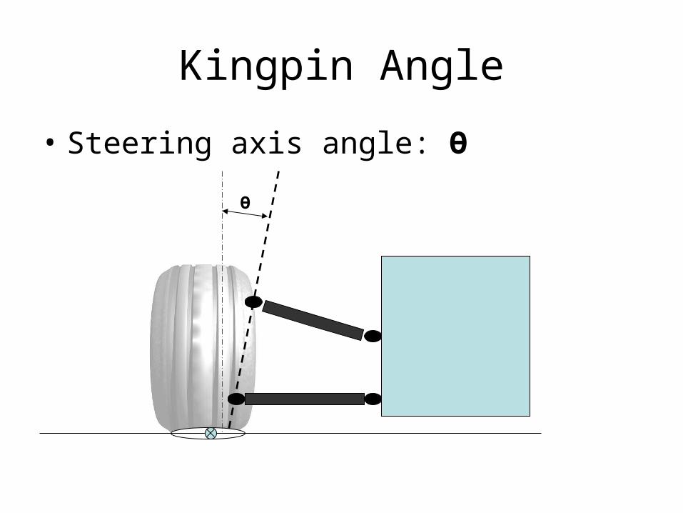
Kingpin Angle
• Steering axis angle: Ө
Ө

Effect of Kingpin Angle
– Typically the is kingpin angled toward the center of the car
– In this case, any turning of the wheel forces the tire to arc toward the ground
– This causes this corner of the vehicle to be raised, providing a self centering force on the steering system

Caster
• The angle of the steering axis as viewed from a side view
Front of Car
Positive Negative

Positive Caster
• When the wheel is turned the cornering force acts perpendicular to the wheel through the contact patch.– creates a torque about the steering axis
that acts to center the steering system
Positive
Front of Car

Negative Caster
• This has the opposite effect as positive caster– As the tires are turned a torque is created that
cause the tire to turn farther
Front of Car
Negative

Caster
• The torque created by caster is a large factor in providing feedback for a driver.
• These aligning torques are responsible for allowing a driver to recover form a spin.
• These forces are present any time the wheel is turned at an angle to the vehicle trajectory
Trajectory

Effects of Caster Dynamic Camber
• From a performance standpoint the caster can be used to achieve the desired camber for a given situation.
• Positive Caster: Adds negative to outside tire in a cornering situation, Optimal for traction

Bump Steer• Steer angle generated any time the suspension travels up or down• Created any time the steering rod inboard pivot is not located on the instant
center• Causes tires to toe in or out with steer angle
CHASSIS
Instant Center
Ground
Steering Rod (Toe Rod)
Steering Rod Inboard Pivot

Bump Steer• Can be used for performance tuning
• Can be used on the rear suspension to create passive rear steer
CHASSIS
Instant Center
Ground

Passive Rear Steer
• Relies on the vehicle roll angle during a cornering situation to steer the rear wheels
CHASSIS
Ground
Toe Rod

Steering Ackerman
• Steering Ackerman describes the angle difference between the outside and inside tire of a vehicle
• The steering sensitivity of the vehicle is greatly affected by the amount of Ackerman designed into the suspension

Corner Conditions
• When the vehicle negotiates a turn the two front wheels must carve different arc, the outside wheel travels a further distance than the inner

Parallel Steering
• Parallel steering means that both front tires are turned the same amount to navigate a given corner
• This will work but it reduces the effectiveness of the steering system
• If both the wheels were turned by the same amount, the inside wheel would scrub (effectively sliding sideways)
• So to eliminate this scrubbing of the inside tire, the tire needs to be steered more to carve the same arc

Drawing out Ackerman• To visualize Ackerman
steering geometry you can draw it out on the vehicle lay out– First draw a vehicle
center line – Draw a line down the
center of the rear axle– Then draw a line
intersecting the outer steering point and the kingpin axis
• The intersection of the two dotted lines defines the Ackerman characteristics of the vehicle

True Ackerman
• For a vehicle to have true Ackerman all of the wheels must pivot around the same point
• This ensures that no tire is unnecessarily scrubbing, so this means that both tires are traveling tangent to the circle the vehicle is traveling on.
• When the outer steering attachment falls anywhere on the pink line the vehicle will have the same true Ackerman

Over True Ackerman
• Over Ackerman refers to the inside tire turning more then the amount required to travel the desired arc
• This case shows how the intersection point falls in front of the rear axle center line, thus increasing the angle difference between the two tires
• So it could be described as have toe out in relation to the turning circle
• In most cases this is done for low speed cars that require nimble quick turning, the vehicle will have increased steering response at low speeds

Under True Ackerman• In this setup the
intersection point falls behind the axle center
• This causes the steering response of the vehicle to decrease slightly
• So it could be described as have toe in in relation to the turning circle
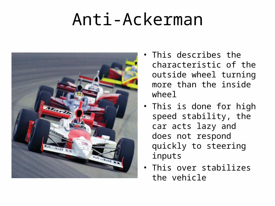
Anti-Ackerman
• This describes the characteristic of the outside wheel turning more than the inside wheel
• This is done for high speed stability, the car acts lazy and does not respond quickly to steering inputs
• This over stabilizes the vehicle

Drawing Anti-Ackerman
• When drawing out Anti-Ackerman, imagine the Ackerman drawing just mirrored around the front axle centerline
• The steering angle difference would be the same as normal Ackerman, just that the outside tire is now turning more then the inside

Steering Ratio
• The steering ratio can be adjusted by moving the outer steering pickup point along the Ackerman Axis (dotted line), and still maintain the Ackerman geometry
• This action will decrease the steering effort required, but it will also slow the steering

Roll Gradient
• Relationship between vehicle roll angle (body roll) and lateral acceleration.
• Units: Degrees / G
• This is usually a design target that a designer will use while designing the suspension

Roll Stiffness
• If you know the roll stiffness of a car and the CG and roll center height, you can calculate the roll gradient
b = roll moment
)(deg/GR
bxR
stiffness
lateralgrad