Static and dynamic simulations for automotive interiors components using · PDF...
12
2012 SIMULIA Community Conference 1 Static and dynamic simulations for automotive interiors components using ABAQUS Mauro Olivero, Vincenzo Puleo, Massimo Barbi, Fabrizio Urbinati, Benedetta Peyron Fiat Research Centre Giancarlo Luciani, Alberto Novarese Fiat Group Automobiles S.p.A. Abstract: Over the last years the car manufacturers have been working intensively to improve the quality of the interiors since it is extremely important to the customer’s perception of the car. The numerical simulation can help the development of the interiors components design in order to guarantee better structural performances and to increase the quality of the products and therefore it is important to develop new calculation methodologies. In this paper, we will present two methodologies developed to improve the quality and efficiency of dashboards. The first one concerns the dynamic simulation of the passenger air bag cover opening: the key points of the activity are the characterization of a polymeric material with a high elongation at break, the development of a simplified model of the airbag’s tear seams and the setup of a process that can be included into an optimization loop. The second one concerns the simulation of the opening and the closure of the glove box: in this case the key point are the development of a functional model of the locking mechanism and of the interactions between the glove box and the various components that affect the opening and closing minimum load, like the rubber bumpers and the internal light switch. Both the methodologies have been validated by means of a series of experimental tests and therefore it can be used during the design development process. Keywords: Air-bag, Collapse, Connectors, Damage, Dashboard, Fracture & Failure, Glove box, Mechanisms, Polymer. 1. Introduction In the last years, current market request to reduce the time and cost development. In order to achieve this result, virtual simulations play an important role since they allow to minimize the number of experimental tests. The two numerical methodologies that we are going to show can help the development of the interiors components design in order to improve the structural performances and to increase the quality of dashboards. The simulation of the passenger air bag cover opening is a dynamic simulation made with Abaqus/Explicit: a rigid impactor hits a portion of the dashboard containing the passenger air bag
Transcript of Static and dynamic simulations for automotive interiors components using · PDF...

2012 SIMULIA Community Conference 1
Static and dynamic simulations for automotive interiors components using ABAQUS
Mauro Olivero, Vincenzo Puleo, Massimo Barbi,
Fabrizio Urbinati, Benedetta Peyron
Fiat Research Centre
Giancarlo Luciani, Alberto Novarese
Fiat Group Automobiles S.p.A.
Abstract: Over the last years the car manufacturers have been working intensively to improve the
quality of the interiors since it is extremely important to the customer’s perception of the car.
The numerical simulation can help the development of the interiors components design in order to
guarantee better structural performances and to increase the quality of the products and therefore
it is important to develop new calculation methodologies.
In this paper, we will present two methodologies developed to improve the quality and efficiency
of dashboards.
The first one concerns the dynamic simulation of the passenger air bag cover opening: the key
points of the activity are the characterization of a polymeric material with a high elongation at
break, the development of a simplified model of the airbag’s tear seams and the setup of a process
that can be included into an optimization loop.
The second one concerns the simulation of the opening and the closure of the glove box: in this
case the key point are the development of a functional model of the locking mechanism and of the
interactions between the glove box and the various components that affect the opening and closing
minimum load, like the rubber bumpers and the internal light switch.
Both the methodologies have been validated by means of a series of experimental tests and
therefore it can be used during the design development process.
Keywords: Air-bag, Collapse, Connectors, Damage, Dashboard, Fracture & Failure, Glove box,
Mechanisms, Polymer.
1. Introduction
In the last years, current market request to reduce the time and cost development. In order to
achieve this result, virtual simulations play an important role since they allow to minimize the
number of experimental tests.
The two numerical methodologies that we are going to show can help the development of the
interiors components design in order to improve the structural performances and to increase the
quality of dashboards.
The simulation of the passenger air bag cover opening is a dynamic simulation made with
Abaqus/Explicit: a rigid impactor hits a portion of the dashboard containing the passenger air bag

2 2012 SIMULIA Community Conference
module. In order to correctly evaluate the opening force of the cover bag it is necessary to
implement a simplified model of the airbag’s tear seams.
The simulation of the opening and the closure of the glove box is a static simulation made with
Abaqus/Standard: in order to correctly evaluate the opening and closing force it is very important
to implement a correct model of the locking mechanism and to simulate the interactions between
the glove box and all the various components involved during the closure and the opening.
2. Cover bag collapse simulation
The starting point of this work is to understand the complexity related to the designing phase of
interiors components and, in particular, the zone of the dashboard under witch is placed the
passenger airbag system.
During the development of the component, the designer has a lot of task to take into account:
• guarantee the correct opening of the cover under the pyrotechnical load coming from the
airbag system;
• avoid tears during the deployment of the air bag (Figure 1);
• avoid sharp corners on the area interested by the head impact;
• avoid unexpected failure in the dashboard due to the airbag inflation (Figure 1).
Figure 1. Examples of problems related to incorrect air bag deployment
The setup of this component is very complex, since there is a lot of technical requests that have to
be fulfilled and the physical problem is guided by many designing parameters that are related one
to each other by very complex relationships.
Up today, the development of the component is made by a huge number of experimental tests,
made to calibrate the designing parameters, like the distance between the holes, the residual
thickness and the shape of the opening line of the cover. This generates a big amount of work
made in conjunction by the car maker and the supplier: this is why CRF and Fiat decided to
develop a methodology to virtually simulate this kind of phenomena: once the methodology will
be ready to be used into the designing phase of the cover bag, this could reduce the amount of
experimental test to calibrate the component and reduce the development cost of the component
itself.

2012 SIMULIA Community Conference 3
2.1 Numerical model of the cover bag material
Polymeric materials show a very complex mechanical behavior that could be resumed in few
point:
• they show a mechanical behavior which is strongly dependent from the temperature and
from the strain rate;
• the elastic modulus is a function of strain rate and plastic strain;
• polymers have different hardening behavior in tension, compression and shear;
• the volume is not constant during the plastic deformation, since during the plastic
deformation, polymers show a phenomena called crazing, which is basically the
nucleation of voids inside the material that generate an increase of the volume during the
deformation.
In order to calibrate our numerical model of the material, we started from experimental tensile test
made at different value of strain rate and at different values of temperatures.
Another important issue that we included in our numerical simulation is the possibility to take into
account of yielding criteria related with the pressure and the volumetric variation during the plastic
deformation. We developed a numerical model of material which has the following characteristics:
• the yielding shows a linear variation with respect to the pressure;
• the plastic deformation is not isochoric;
That could be done by an optical measurement made during the tensile test: starting from the
measurement of the transversal and the longitudinal strains on the specimen during the tensile load
and by some considerations about the trough the thickness strain, we obtained the experimental
curve of the volume variation over the strain.
Starting from this curve, we implemented our numerical model of the material in order to fit this
behavior and we could fit quite well the experimental results: in Figure 2 we can see the
comparison between experimental (orange) and the numerical test (blue).
Figure 2. Volume variation (correlation between numerical and experimental results)

4 2012 SIMULIA Community Conference
To complete the description of the numerical modeling of polymeric material we have to show the
correlation of the stress – strain curve in the tensile test between numeric model and experimental
test: in Figure 3 we can see that the behavior of the numerical model (red line) is very similar to
the experimental test (blue line).
Figure 3. Tensile test (correlation between numerical and experimental results)
2.2 Characterization and modeling of airbag’s tear seams
In Figure 4 there are some picture showing the process of creation of the micro holes in the cover
bag: a laser is guided by a robot over rear part of the cover bag to create micro holes: this
operation makes the section weaker to force the opening of the cover bag along the tear lines
during the deployment. On the front part of the cover, a residual wall thickness is kept to hide the
tear line to the eyes of the passenger; the parameter design are the diameter of the hole, the
residual wall thickness (the hole penetration) and the distance between the holes.
Figure 4. Micro holes created by a laser machine

2012 SIMULIA Community Conference 5
From a numerical point of view the problem is how to simulate in a simple way these micro holes
in a FEM analysis, since the dimensions of the holes are so small that the discretization of the
finite element should be so accurate to become computationally unmanageable.
The strategy is to simulate a small portion of the cover with a detailed model of the holes using the
material model calibrated in the previous step: this kind of simulation is quite expensive in term of
computational time and has to be reduce to a small part of the component but, at the end you can
get information about the failure of the section in which are placed the micro holes. The same
simulation is repeated with a simplified model with shell elements (which are more suitable for
large scale model because they are easier to model and less expensive in terms of computational
time): obviously, the zone of the hole has been modeled with a material that has to be calibrated,
starting from the base material, to obtain the same behavior of the detailed model (Figure 5).
Since we have to find a way to scale the material of the simplified model in order to match the
behavior of the detailed one, the main idea is to scale it according to the geometric parameters of
the two sections.
Figure 5. Calibration of a simplified shell model of the micro holes
In order to validate the simplified model, we compared the behavior of the numerical models
under bending load (Figure 6): the maximum force is quite the same for the two model and the
displacement at which the failure occurs is pretty the same.
Figure 6. Comparison between detailed and simplified model
6 2012 SIMULIA Community Conference
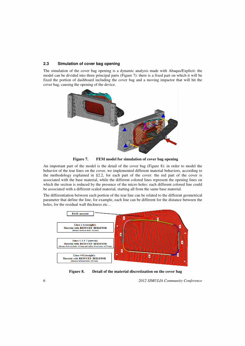
2.3 Simulation of cover bag opening
The simulation of the cover bag opening is a dynamic analysis made with Abaqus/Explicit: the
model can be divided into three principal parts (Figure 7): there is a fixed part on which it will be
fixed the portion of dashboard including the cover bag and a moving impactor that will hit the
cover bag, causing the opening of the device.
Figure 7. FEM model for simulation of cover bag opening
An important part of the model is the detail of the cover bag (Figure 8): in order to model the
behavior of the tear lines on the cover, we implemented different material behaviors, according to
the methodology explained in §2.2, for each part of the cover: the red part of the cover is
associated with the base material, while the different colored lines represent the opening lines on
which the section is reduced by the presence of the micro holes: each different colored line could
be associated with a different scaled material, starting all from the same base material.
The differentiation between each portion of the tear line can be related to the different geometrical
parameter that define the line, for example, each line can be different for the distance between the
holes, for the residual wall thickness etc…
Figure 8. Detail of the material discretization on the cover bag

2012 SIMULIA Community Conference 7
2.4 Results
Finally, we can show the comparison with the experimental test in order to validate the numerical
methodology: the actuator of the real testing machine is a pneumatic cylinder; at the head of the
cylinder is placed a force transducer and, after that we have the impactor that will hit the cover
bag.
In Figure 9 we can see the comparison between experimental and numerical results: the blue curve
represents the experimental result, while in red we have the numerical result.
The correlation is quite good: on the X axis ha have the displacement of the impactor and we can
see that the displacement on which the failure occurs in the numeric model causing the opening of
the cover bag is really similar to the experimental result.
On the Y axis we have the opening force: here we can see that the numerical model shows a little
overestimation of the opening force (about 10%), but we can say at the end that the model is
predictive of the phenomena and could be used to help the designers in the development phase of a
new dashboard.
Figure 9. Comparison between experimental and numerical results
Certainly, the model could also be improved and we are working on it in order to reduce the
distance between experimental and numerical results: for example we are working on the
possibility of take into account for the different behavior in compression and shear and we are also
thinking about the possibility of taking into account of the molding process: in fact, we usually
consider this kind of polymers like a isotropic materials but the molding process could create big
differences in the mechanical behavior of a polymeric component, depending on the flow direction
during molding process.
8 2012 SIMULIA Community Conference
3. Glove box opening and closure simulation
The second part of this work concerns the design of glove boxes. During the development of this
component, the designer has to take into account for a lot of different tasks:
• guarantee the correct opening and closure of the device;
• limit the opening and closing forces under a certain threshold;
• avoid unexpected gaps that can reduce the quality perception of the dashboard in the zone
of the glove box;
• guarantee all the structural performances in terms of stiffness, strength and safety
behavior.
Sometimes it happens that, during the designing phase, there could be some problems related to
the closure of the glove box, since in some cases the closure cannot be reached correctly. The
designing parameters involved in this particular are different: the stiffness of the entire module is
important, but also the behavior of the springs and the configuration of the locking device play an
important role.
Up today, the experimental tests are very important to help the designer to develop the component,
but the numerical simulation could reduce the amount of experimental tests during the designing
phase, therefore CRF and Fiat decided to develop a methodology to simulate the opening and
closure of glove boxes.
3.1 Finite element model of the glove box
The simulation of the closure and opening of the glove box is a static analysis made with
Abaqus/Standard: starting from a complete model of the dashboard, we created a reduced model
including the glove box module, the rubber bumpers and the light switch. All the possible contacts
between the parts were considered.
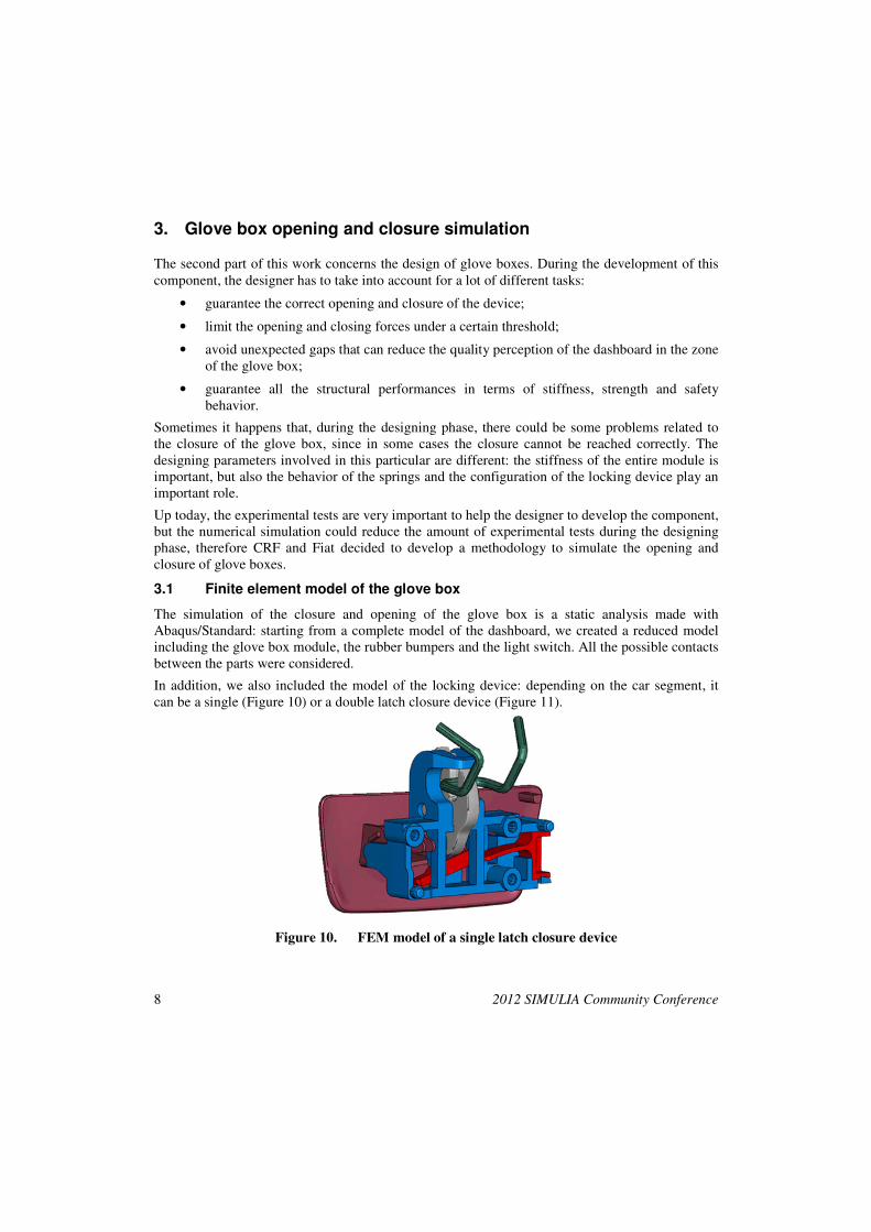
In addition, we also included the model of the locking device: depending on the car segment, it
can be a single (Figure 10) or a double latch closure device (Figure 11).
Figure 10. FEM model of a single latch closure device

2012 SIMULIA Community Conference 9
Figure 11. FEM model of a double latch closure device
The modeling of the locking device is very important to achieve an accurate evaluation of the
closing and opening forces of the glove box: both the two types of device are a mixture of
deformable, rigid and connector element: all the parts involved in contact were modeled like
deformable parts; hinges, springs, bumpers and mechanisms (like the double rack and pinion in
Figure 11) were modeled with connector elements (CONN3D2); all the remaining parts were
defined as rigid.
3.2 Closure simulation
Starting from the glove box model described in §3.1, to complete the closure simulation we first
rotated the door with a rigid rotation around the hinges removing the contact on the locking
device.
Once the minimum opening condition were reached, we started pushing on the door with a
pushing device until the complete closure of the glove box is reached (Figure 12): during the
simulation, the reaction force on the pushing device is recorded and therefore it is possible to see
the different contribution of the part in contact (latch, rubber bumpers, light switch) to the overall
closing force.
Figure 12. Closure simulation on double latch glove box

10 2012 SIMULIA Community Conference
The simulation were repeated putting the pushing device in difference position, in order to
evaluate if the closure could be reached in every position.
3.3 Opening simulation
Starting from the closure condition of the glove box described in §3.2, we implemented the model
for the opening simulation by connecting a connector element to the handle and then by using a
*CONNECTOR MOTION to pull the handle until the opening is reached (Figure 13).
Figure 13. Opening simulation on single latch glove box
During the simulation, the internal forces of the connector element are stored and therefore it is
possible to see the different contribution of the parts (latch, rubber bumpers, light switch) to the
overall opening force.
3.4 Results
In order to validate the methodology, we have to compare the numerical results with the
experimental test.
For the closure, the experimental test was made by putting the dashboard on a fixed support and
trying to close the glove box by pushing on seven different positions (Figure 14): for each
position, the relative closing force was recorded.

2012 SIMULIA Community Conference 11
Figure 14. Glove box closure experimental test
The same type of analysis was repeated by the numerical simulation and the comparison between
the results is shown in Figure 15: the correlation is very good from point 1 to 6. On point 7, it was
not possible to reach the closure of the glove box during the experimental test, while in the
numerical test we couldn’t reach the convergence due the excessive deformation of the right
rubber bumper.
Also if the comparison on point 7 available, the numerical closing force at the end of the
simulation (if convergence could be reached) should be very high and that could generate a
warning on the real possibility of closing the glove box by pushing on this point.
Figure 15. Closure (comparison between numerical and experimental results)
For the opening, the experimental test was made by connecting a wire to the handle and then by
pulling the wire until the opening is reached.

12 2012 SIMULIA Community Conference
In Figure 16 we have a plot of the reaction force on the handle during the displacement of the
pulling point: the numerical opening force is quite similar to the result of the experimental test.
The numerical opening force underestimates the experimental value but the reason can be related
to the fact that on the opening device there is a stopper that limits the rotation of the handle; this
device starts to operate immediately after the geometrical opening condition and therefore even a
little additional rotation can generate a big increase on the recorded opening force.
Figure 16. Opening (comparison between numerical and experimental results)
4. Conclusions
In recent years, a big effort has been made to increase the capability of simulating interiors
components. Fundamentals parts of the methods developed are the numerical characterization of
polymeric materials, the development of criteria for failure of element during dynamic simulations
and the capability to model complex mechanisms to simulate locking devices.
Comparisons between experimental tests and numerical results have been done and the
correlation is good: the new methodologies can be used into the designing phase of components
and this could reduce the amount of experimental and therefore the development cost of the
components.
5. References
1. Abaqus User’s manual 2011
2. Spingler G., Drazetic P., Markiewicz E., “Dynamic Characterization of Polymers to Improve
Numerical Simulations for Passive Safety”, International Journal of Crashworthiness Vol. X
n°1, 2005
3. Trantina G., Nimmer R., “Structural Analysis of Thermoplastic Components”, MacGraw-Hill
International Editions, 1994