SMA MINUTO rev00 EN
52
All parts of this document are the property of Saeco International Group. All rights reserved. is document and all the information herein is provided without liability deriving from any errors or omissions. Furthermore, no part may be reproduced, used or collected, except where express authorisation has been provided in writing or through a contractual agreement. Published by Saeco International Group Subject to modification EN 4219 400 00020 Service Service Service Service Coffee Machine Minuto Table of contents Page 1. Introduction 1.1. Documentation required 1 1.2. Tools and equipment required 1 1.3. Material 1 1.4. Safety warnings 1 1.5 Service Policy 2 1.6.1. External machine parts 3 1.6.2. Internal machine parts 4 2. Technical specifications 2.1. Technical specifications 1 2.2.1 Specification for the measurement of the coffee products temperature 2 2.2.2. Specification for the measurement of the milk products temperature 3 2.3. Machine parameters and performance 5 3. User instructions 3.1. Customer menu in the Minuto Class and Focus 1 3.2 Operation, cleaning and maintenance 3 4. Operating logic 4.1. Water circuit 1 4.2. Coffee cycle 2 4.3. Single microswitch 3 4.4. Temperature sensor 3 4.5. Coffee grinder 4 4.6. Low bean level detection, dose quantity adjustment, coffee grinder blocked 4 2013-April-30 Table of contents Page 4.7. Dose self-learning (SAS) 5 4.8. Water level detection (water tank) 6 4.9. Descaling request 6 4.10. Water filter 7 5. Troubleshooting 5.1.1. Minuto test mode 1 5.1.2. SteamOut 7 5.2. Error messages 8 6. Standard checks 6.1. Repair schedule 1 6.2. Service schedule 1 6.3. Final test 2 7. Disassembly 7.1. Outer Shell 1 7.2. Coffee grinder 1 7.3. Grinder blades 2 7.4. Coffee grinder adjustment 3 7.5. Two-way solenoid valve 3 7.6. Pin boiler 4 7.7. Gear motor 4 7.8. Central plate 5 7.9. Pump 5 7.10. Flow-meter 6 7.11. Boiler 6 7.12. CPU board 7 Service Service Manual Manual Rev. 00 April 2013
Transcript of SMA MINUTO rev00 EN
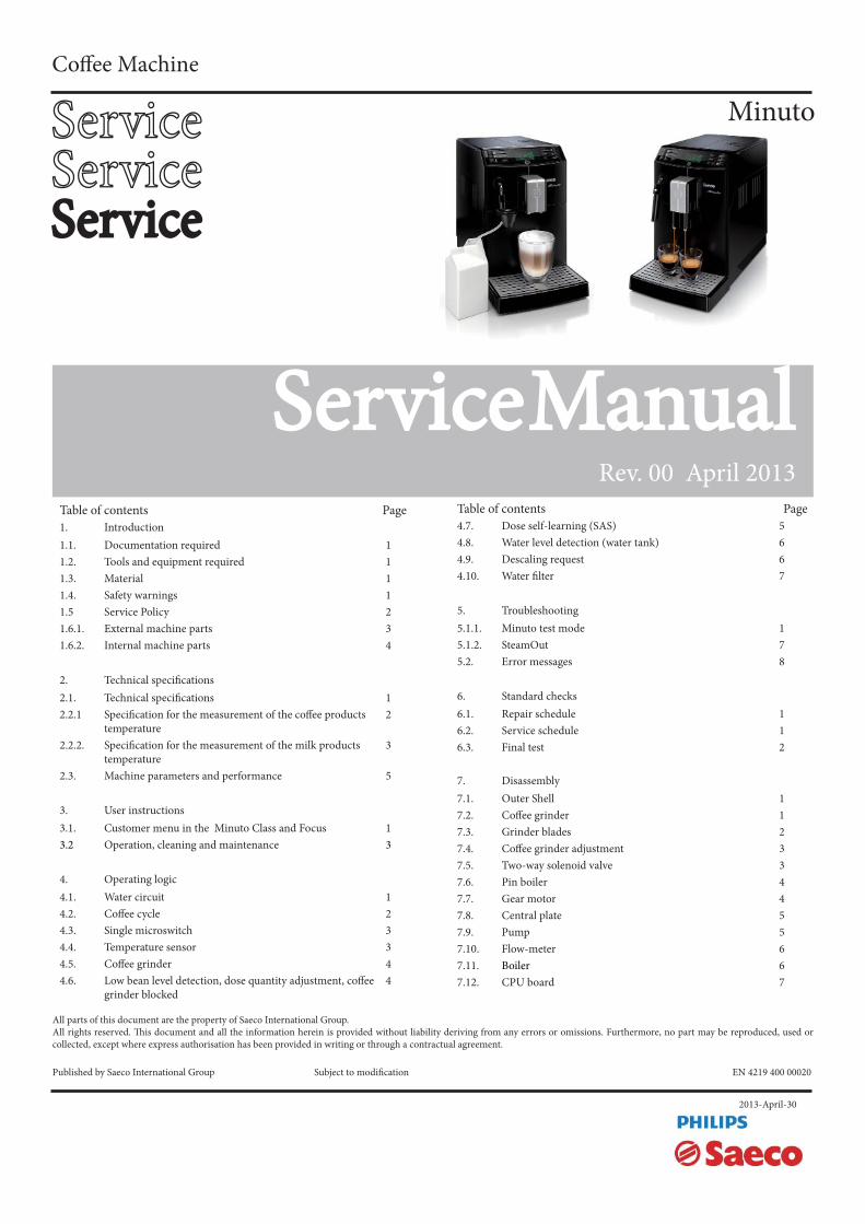
All parts of this document are the property of Saeco International Group.All rights reserved. Th is document and all the information herein is provided without liability deriving from any errors or omissions. Furthermore, no part may be reproduced, used or collected, except where express authorisation has been provided in writing or through a contractual agreement.
Published by Saeco International Group Subject to modifi cation EN 4219 400 00020
ServiceServiceServiceService
Coff ee Machine
Minuto
Table of contents Page1. Introduction1.1. Documentation required 11.2. Tools and equipment required 11.3. Material 11.4. Safety warnings 11.5 Service Policy 21.6.1. External machine parts 31.6.2. Internal machine parts 4
2. Technical specifi cations2.1. Technical specifi cations 12.2.1 Specifi cation for the measurement of the coff ee products
temperature2
2.2.2. Specifi cation for the measurement of the milk products temperature
3
2.3. Machine parameters and performance 5
3. User instructions 3.1. Customer menu in the Minuto Class and Focus 13.2 Operation, cleaning and maintenance 3
4. Operating logic4.1. Water circuit 14.2. Coff ee cycle 24.3. Single microswitch 34.4. Temperature sensor 34.5. Coff ee grinder 44.6. Low bean level detection, dose quantity adjustment, coff ee
grinder blocked4
2013-April-30
Table of contents Page4.7. Dose self-learning (SAS) 54.8. Water level detection (water tank) 64.9. Descaling request 64.10. Water fi lter 7
5. Troubleshooting5.1.1. Minuto test mode 15.1.2. SteamOut 75.2. Error messages 8
6. Standard checks 6.1. Repair schedule 16.2. Service schedule 16.3. Final test 2
7. Disassembly7.1. Outer Shell 17.2. Coff ee grinder 17.3. Grinder blades 27.4. Coff ee grinder adjustment 37.5. Two-way solenoid valve 37.6. Pin boiler 47.7. Gear motor 47.8. Central plate 57.9. Pump 57.10. Flow-meter 67.11. Boiler 67.12. CPU board 7
Service Service ManualManual
Rev. 00 April 2013
MINUTO
Table of contents Page
7.13 Programming access for SSC (Saeco Service Center) 7
7.14. KYB interface and display 7
7.15. Fitting and removing Oetiker clamps 8
8. Notes
9. Water circuit diagram
10 Electrical diagram
MINUTO
CHAPTER 1
INTRODUCTION
MINUTO 01 INTRODUCTION
Page / 04
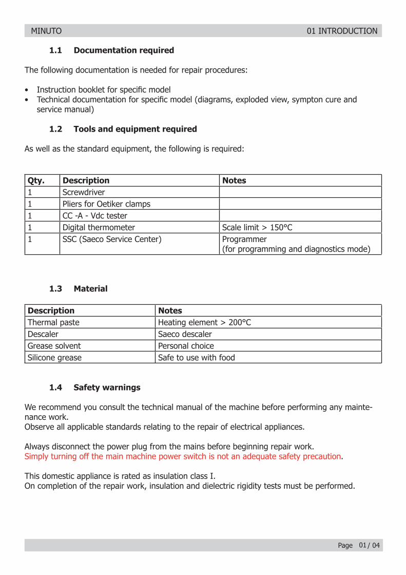
1.1 Documentation required
The following documentation is needed for repair procedures:
• Instruction booklet for specifi c model• Technical documentation for specifi c model (diagrams, exploded view, sympton cure and
service manual)
1.2 Tools and equipment required
As well as the standard equipment, the following is required:
Qty. Description Notes1 Screwdriver1 Pliers for Oetiker clamps 1 CC -A - Vdc tester1 Digital thermometer Scale limit > 150°C1 SSC (Saeco Service Center) Programmer
(for programming and diagnostics mode)
1.3 Material
Description NotesThermal paste Heating element > 200°CDescaler Saeco descalerGrease solvent Personal choiceSilicone grease Safe to use with food
1.4 Safety warnings
We recommend you consult the technical manual of the machine before performing any mainte-nance work.Observe all applicable standards relating to the repair of electrical appliances.
Always disconnect the power plug from the mains before beginning repair work.Simply turning off the main machine power switch is not an adequate safety precaution.
This domestic appliance is rated as insulation class I.On completion of the repair work, insulation and dielectric rigidity tests must be performed.
01
MINUTO 01 INTRODUCTION
Page / 0402
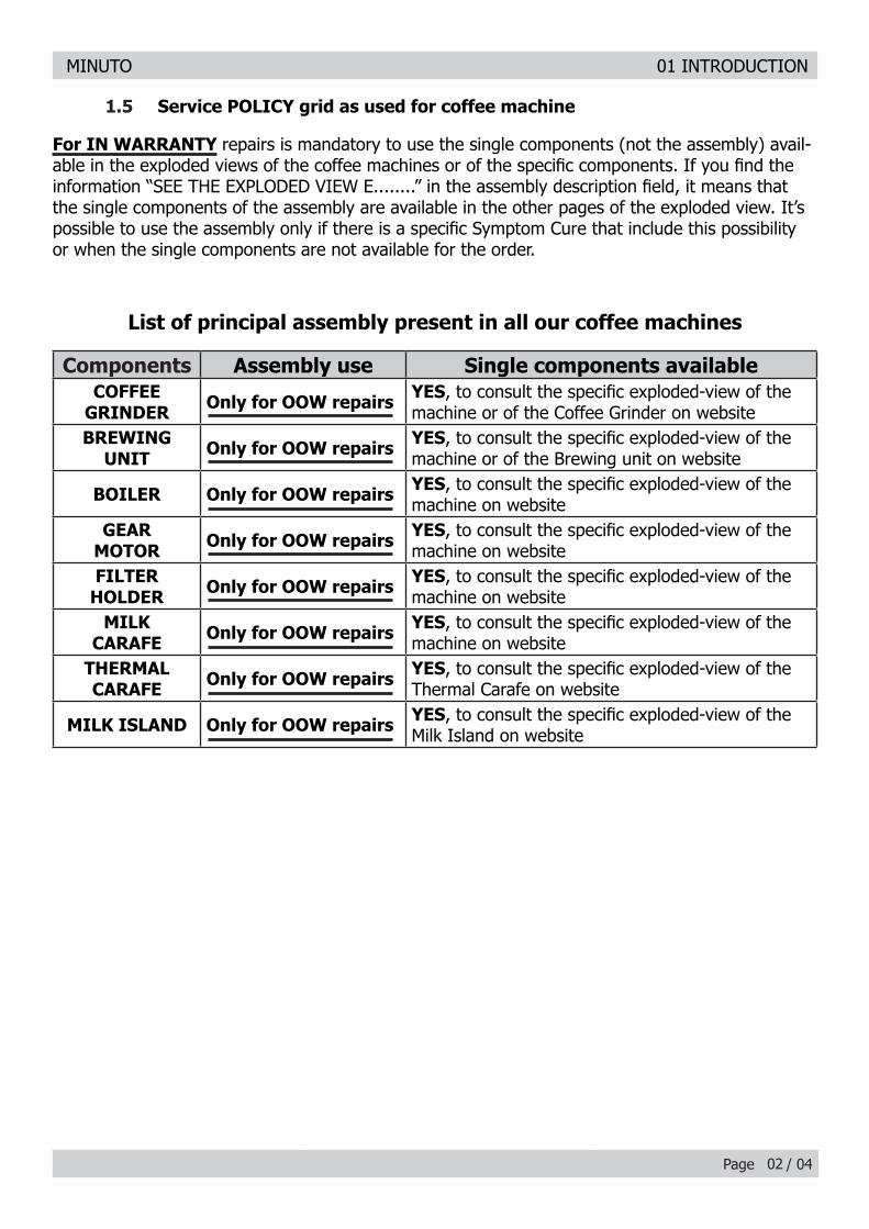
1.5 Service POLICY grid as used for coffee machine
Components Assembly use Single components availableCOFFEE
GRINDER Only for OOW repairs YES, to consult the specifi c exploded-view of the machine or of the Coffee Grinder on website
BREWING UNIT Only for OOW repairs YES, to consult the specifi c exploded-view of the
machine or of the Brewing unit on website
BOILER Only for OOW repairs YES, to consult the specifi c exploded-view of the machine on website
GEAR MOTOR Only for OOW repairs YES, to consult the specifi c exploded-view of the
machine on websiteFILTER
HOLDER Only for OOW repairs YES, to consult the specifi c exploded-view of the machine on website
MILK CARAFE Only for OOW repairs YES, to consult the specifi c exploded-view of the
machine on websiteTHERMAL CARAFE Only for OOW repairs YES, to consult the specifi c exploded-view of the
Thermal Carafe on website
MILK ISLAND Only for OOW repairs YES, to consult the specifi c exploded-view of the Milk Island on website
List of principal assembly present in all our coffee machines
For IN WARRANTY repairs is mandatory to use the single components (not the assembly) avail-able in the exploded views of the coffee machines or of the specifi c components. If you fi nd the information “SEE THE EXPLODED VIEW E........” in the assembly description fi eld, it means that the single components of the assembly are available in the other pages of the exploded view. It’s possible to use the assembly only if there is a specifi c Symptom Cure that include this possibility or when the single components are not available for the order.
MINUTO 01 INTRODUCTION
Page / 04
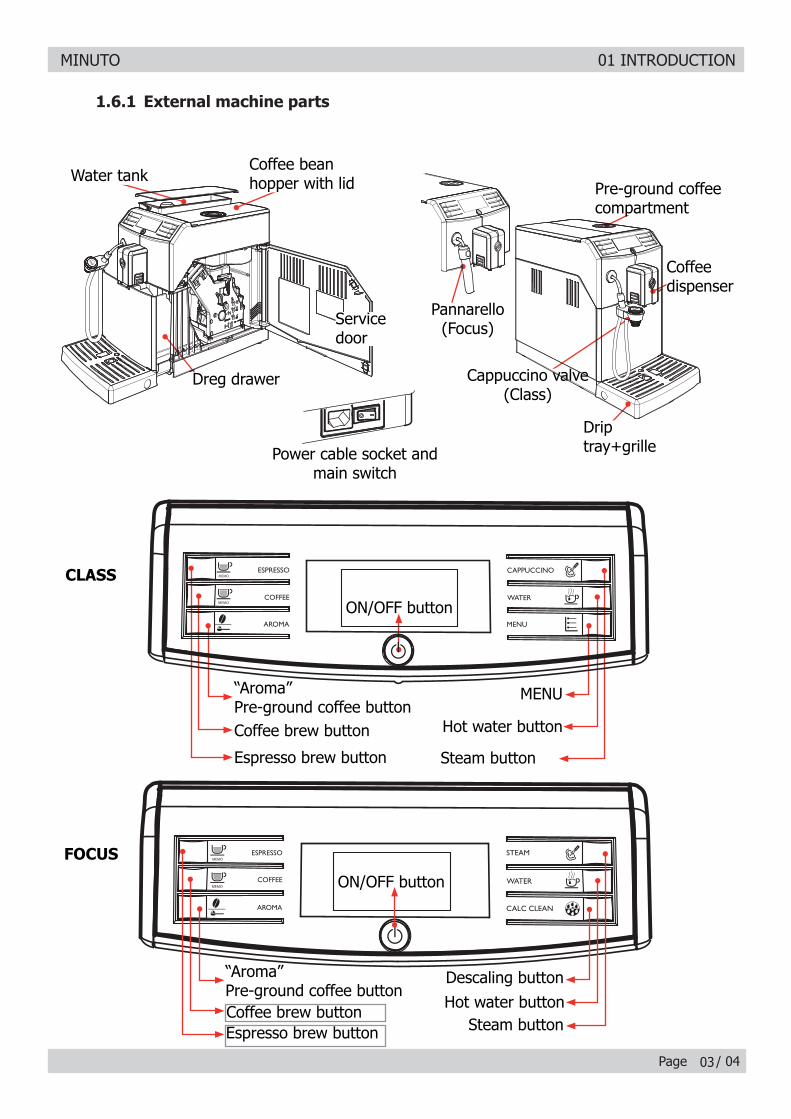
Pannarello(Focus)
Cappuccino valve (Class)
Dreg drawer
Drip tray+grille
1.6.1 External machine parts
Power cable socket and main switch
Coffee dispenser
Water tankPre-ground coffee compartment
03
FOCUS
Descaling button
ON/OFF button
Hot water buttonSteam buttonEspresso brew button
Coffee brew button
“Aroma”Pre-ground coffee button
CLASS
Steam button
ON/OFF button
Hot water button
MENU
Espresso brew button
Coffee brew button
“Aroma”Pre-ground coffee button
Service door
Coffee bean hopper with lid
MINUTO 01 INTRODUCTION
Page / 04
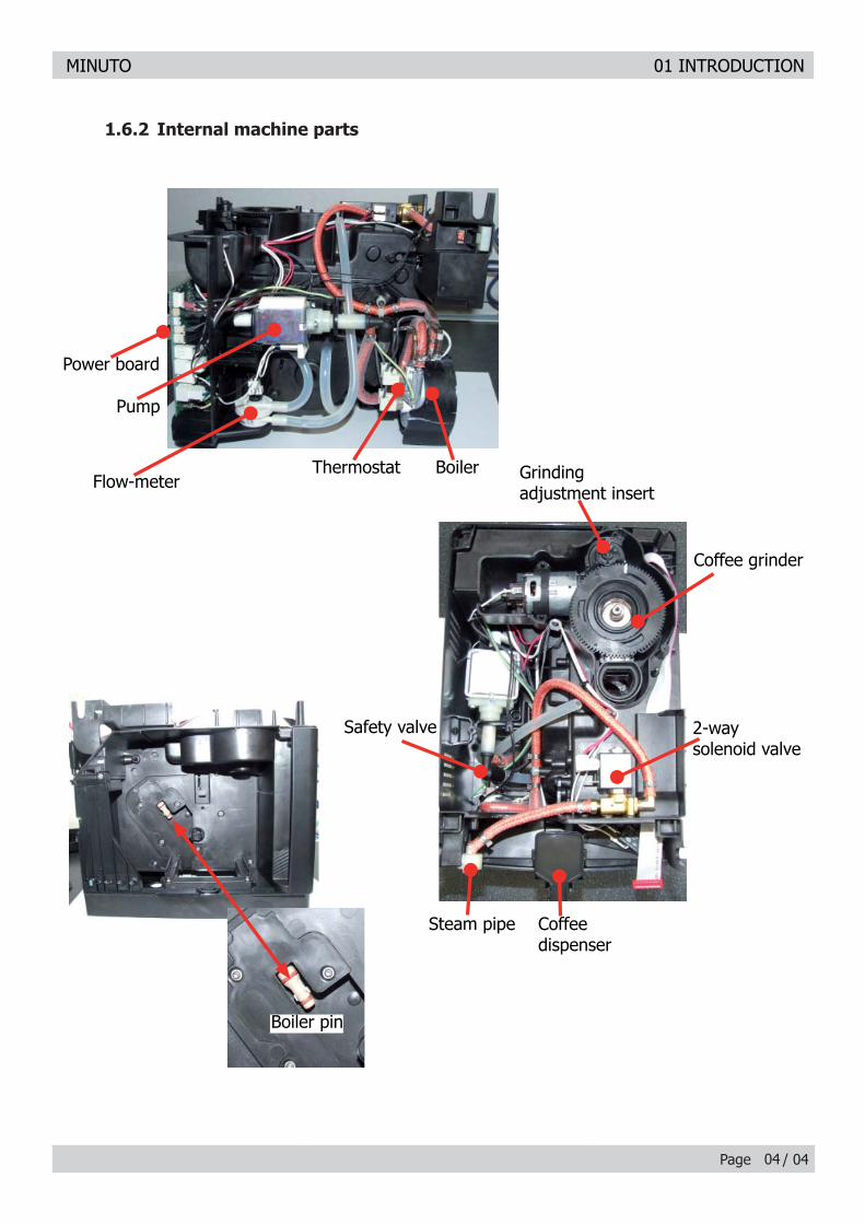
1.6.2 Internal machine parts
04
Safety valve
Coffee dispenser
Grinding adjustment insert
Steam pipe
2-way solenoid valve
Coffee grinder
Flow-meter
Power board
BoilerThermostat
Pump
Boiler pin
MINUTO
CHAPTER 2 TECHNICAL
SPECIFICATIONS
MINUTO 02 TECHNICAL SPECIFICATIONS
Page / 05
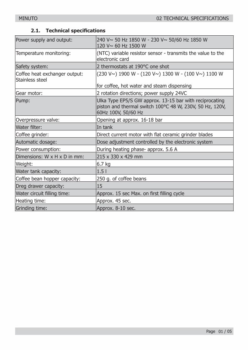
2.1. Technical specifi cations
Power supply and output: 240 V~ 50 Hz 1850 W - 230 V~ 50/60 Hz 1850 W 120 V~ 60 Hz 1500 W
Temperature monitoring: (NTC) variable resistor sensor - transmits the value to the electronic card
Safety system: 2 thermostats at 190°C one shotCoffee heat exchanger output: Stainless steel
(230 V~) 1900 W - (120 V~) 1300 W - (100 V~) 1100 W
for coffee, hot water and steam dispensingGear motor: 2 rotation directions; power supply 24VCPump: Ulka Type EP5/S GW approx. 13-15 bar with reciprocating
piston and thermal switch 100°C 48 W, 230V, 50 Hz, 120V, 60Hz 100V, 50/60 Hz
Overpressure valve: Opening at approx. 16-18 barWater fi lter: In tank Coffee grinder: Direct current motor with fl at ceramic grinder blades Automatic dosage: Dose adjustment controlled by the electronic system Power consumption: During heating phase- approx. 5.6 ADimensions: W x H x D in mm: 215 x 330 x 429 mmWeight: 6.7 kg Water tank capacity: 1.5 lCoffee bean hopper capacity: 250 g. of coffee beansDreg drawer capacity: 15Water circuit fi lling time: Approx. 15 sec Max. on fi rst fi lling cycleHeating time: Approx. 45 sec.Grinding time: Approx. 8-10 sec.
01
MINUTO 02 TECHNICAL SPECIFICATIONS
Page / 0502
2.2.1. Specifi cation for the measurement of the coffee products temperature.
The temperature is infl uenced by the fl ow from the dispenser and stratifi cation of temperatures in the glass. In order to consider these phenomena and to introduce measures that allow compari-sons in controlled conditions, below guidelines must be followed:
Conditions:a) Water temperature in tank: 23°C (+/-2°C).
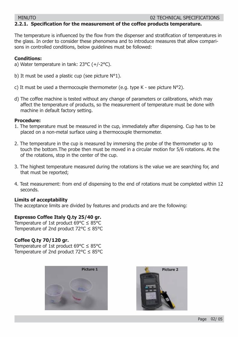
b) It must be used a plastic cup (see picture N°1).
c) It must be used a thermocouple thermometer (e.g. type K - see picture N°2).
d) The coffee machine is tested without any change of parameters or calibrations, which may affect the temperature of products, so the measurement of temperature must be done with machine in default factory setting.
Procedure:1. The temperature must be measured in the cup, immediately after dispensing. Cup has to be placed on a non-metal surface using a thermocouple thermometer.
2. The temperature in the cup is measured by immersing the probe of the thermometer up to touch the bottom.The probe then must be moved in a circular motion for 5/6 rotations. At the of the rotations, stop in the center of the cup.
3. The highest temperature measured during the rotations is the value we are searching for, and that must be reported;
4. Test measurement: from end of dispensing to the end of rotations must be completed within 12 seconds.
Limits of acceptabilityThe acceptance limits are divided by features and products and are the following:
Espresso Coffee Italy Q.ty 25/40 gr.Temperature of 1st product 69°C ≤ 85°CTemperature of 2nd product 72°C ≤ 85°C
Coffee Q.ty 70/120 gr.Temperature of 1st product 69°C ≤ 85°CTemperature of 2nd product 72°C ≤ 85°C
Picture 1 Picture 2
MINUTO 02 TECHNICAL SPECIFICATIONS
Page / 0503
2.2.2. Specifi cation for the measurement of the Milk products temperature.
Milk evaluationTo carry out the test, a partially skimmed UHT milk with a percentage of grease between 1.5-1.8% at a refrigerator temperature Trefr. (between 4 to 10°C) must be used.The milk product must be checked on a beaker of 250 ml of capability and with an inner diameter of 70mm, brewing 100gr of product.
Parameters to be respected:The parameters to be respected are: milk temperature and height of the cream. Each of these parameters, however, must be evaluated depending on the type of system used for the production of hot milk.Actually three types of devices are present on the appliances: - Manual system (pannarello)- Semi-Automatic system (cappuccinatore)- Automatic system (carafe, Pinless wonder system, etc.)
Milk temperature in the beaker:System without Pinless Wonder: e.g. Xelsis, Exprelia, Syntia, Intelia. With milk at Trefr. (about 4-10 °C): ≥ 36
System with Pinless Wonder: New royal, Energica Pure, Intelia EVO Latte. With milk at Trefr. (about 4-10 °C): ≥ 45
Height of the milk cream in the beaker:Manual system (pannarello) ≥ 15mm on 100gr. of brewed product
Semi-automatic system (cappuccinatore) ≥ 20mm on 100gr. of brewed product
Automatic system: carafe, cappuccinatore, Pinless wonder (New Royal, Energica Pure, Intelia EVO latte) ≥ 20mm on 100gr. of brewed product
How to measure the temperature of the milk.1) The measurement is carried out in the beaker, immediately after the end of milk brew, positioned on a non-metallic surface, using a thermocouple thermometer (eg. Type K). Stop the preparation of mixed product: at the end of milk brewing, where “One Touch product” function is present.
2) The temperature is measured by immersing the probe of the thermometer, positioning the probe inside the beaker at about 10mm from the bottom of the container, then the probe moves in a circular motion for 3-5 turns, stopping at the end, at the center of the beaker. It detects the maximum temperature reached in a time of relief between 3 to 5 seconds. It is important the mixing of milk before the measurement at 10mm from the bottom of the beaker. If the mixing is correct, temperature, for a few fractions of a second, during the measurement should not oscillate.
MINUTO 02 TECHNICAL SPECIFICATIONS
Page / 05
How to measure the milk cream.The temperature (Trefr or Tamb) of the milk doesn’t affect as much the test result on measuring the milk cream; by convection is assumed to always use milk at refrigerator temperature Trefr..
Manual systems (Pannarello)Pour 100cc. of milk at Trefr. in a beaker of 250 ml of capacity and with a inner diameter of 70 mm; with machine in steam mode:
1. Open the steam knob to discharger water circuit for 4 sec, then close the knob. 2. Place the beaker with the frother dipped in milk, open the steam knob to maximum and start the chronometer.3. After about 30 to 60 seconds, close the knob and check the result on milk.
Semi-automatic systems (cappuccino)Pours milk at Trefr. in a container ; with the machine in steam mode:
1. Open the steam knob to discharge water circuit for 4 sec. then close the knob. 2. Insert the silicone tube in the milk container, placing a beaker of 250 ml capacity and with an inner diameter of 70 mm under the cappuccino maker and open the steam knob. 3. After having provided 100gr. of product, close the knob and check the result obtained on milk. Note: The same applies to machines which have a steam key on the user interface and a solenoid valve in place of the steam tap.
Automatic: Carafe, Cappuccino Pinless wonder (New Royal, Energica Pure, Intelia EVO Latte), etc..After setting the machine to delivery of 100gr. of product:
1. Launch the “hot milk” function. 2. Collect the product in a beaker with a 250ml of capacity and with an inner diameter of 70 mm, and verify the result obtained on milk. Carry out the test using milk at a Trefr..
In case the machine allows modify of the emulsion through the menu, use the machine with the emulsion set to the default value.
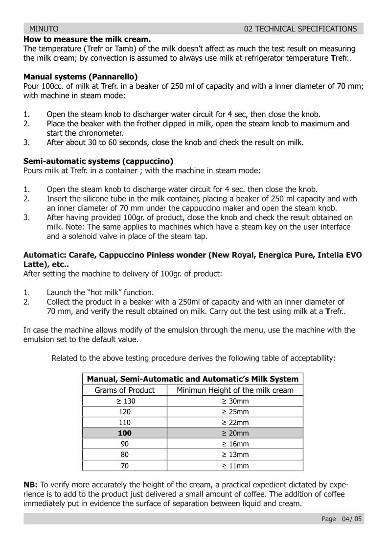
Related to the above testing procedure derives the following table of acceptability:
Manual, Semi-Automatic and Automatic’s Milk SystemGrams of Product Minimun Height of the milk cream
≥ 130 ≥ 30mm120 ≥ 25mm110 ≥ 22mm100 ≥ 20mm90 ≥ 16mm80 ≥ 13mm
70 ≥ 11mm
NB: To verify more accurately the height of the cream, a practical expedient dictated by expe-rience is to add to the product just delivered a small amount of coffee. The addition of coffee immediately put in evidence the surface of separation between liquid and cream.
04
MINUTO 02 TECHNICAL SPECIFICATIONS
Page / 05
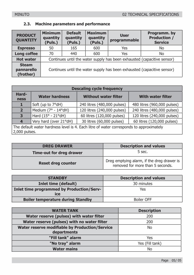
2.3. Machine parameters and performance
PRODUCT QUANTITY
Minimum quantity(Puls.)
Default quantity(Puls.)
Maximum quantity(Puls.)
User programmable
Programm. by Production /
ServiceEspresso 50 165 600 Yes No
Long coffee 70 440 600 Yes NoHot water Continues until the water supply has been exhausted (capacitive sensor)
Steam pannarello (frother)
Continues until the water supply has been exhausted (capacitive sensor)
05
Descaling cycle frequencyHard-ness Water hardness Without water fi lter With water fi lter
1 Soft (up to 7°dH) 240 litres (480,000 pulses) 480 litres (960,000 pulses)2 Medium (7° - 14°dH) 120 litres (240,000 pulses) 240 litres (480,000 pulses)3 Hard (15° - 21°dH) 60 litres (120,000 pulses) 120 litres (240,000 pulses)4 Very hard (over 21°dH) 30 litres (60,000 pulses) 60 litres (120,000 pulses)
The default water hardness level is 4. Each litre of water corresponds to approximately 2,000 pulses.
WATER TANK DescriptionWater reserve (pulses) with water fi lter 200
Water reserve (pulses) with no water fi lter 200Water reserve modifi able by Production/Service
departmentsNo
"Fill tank" alarm Yes"No tray" alarm Yes (Fill tank)
Water mains No
DREG DRAWER Description and values
Time-out for dreg drawer 5 sec.
Reset dreg counter Dreg emptying alarm, if the dreg drawer is removed for more than 5 seconds.
STANDBY Description and valuesInlet time (default) 30 minutes
Inlet time programmed by Production/Serv-ice
Yes
Boiler temperature during Standby Boiler OFF
MINUTO
CHAPTER 3 USER INSTRUCTIONS
MINUTO 03 USER INSTRUCTIONS
Page / 03
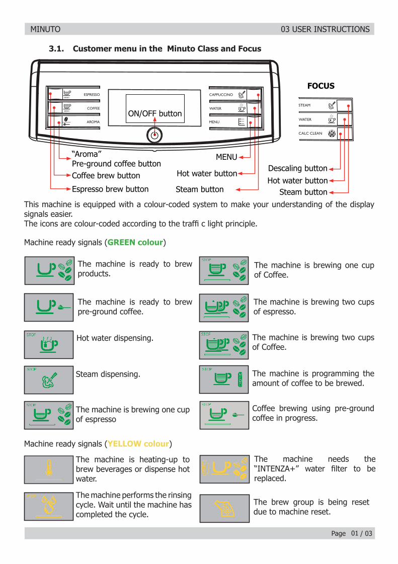
3.1. Customer menu in the Minuto Class and Focus
01
This machine is equipped with a colour-coded system to make your understanding of the display signals easier. The icons are colour-coded according to the traffi c light principle.
The machine is ready to brew products.
The machine is ready to brew pre-ground coffee.
Hot water dispensing.
Steam dispensing.
The machine is brewing one cup of espresso
The machine is heating-up to brew beverages or dispense hot water.
The machine performs the rinsing cycle. Wait until the machine has completed the cycle.
The brew group is being reset due to machine reset.
The machine needs the “INTENZA+” water fi lter to be replaced.
The machine is brewing one cup of Coffee.
The machine is brewing two cups of espresso.
The machine is brewing two cups of Coffee.
The machine is programming the amount of coffee to be brewed.
Coffee brewing using pre-ground coffee in progress.
Machine ready signals (GREEN colour)
Machine ready signals (YELLOW colour)
Steam button
ON/OFF button
Hot water button
MENU
Espresso brew button
Coffee brew button
“Aroma”Pre-ground coffee button
FOCUS
Descaling buttonHot water button
Steam button
MINUTO 03 USER INSTRUCTIONS
Page / 03
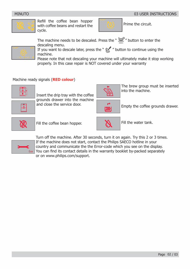
Refi ll the coffee bean hopper with coffee beans and restart the cycle.
Prime the circuit.
Insert the drip tray with the coffee grounds drawer into the machine and close the service door.
Turn off the machine. After 30 seconds, turn it on again. Try this 2 or 3 times.If the machine does not start, contact the Philips SAECO hotline in yourcountry and communicate the the Error-code which you see on the display.You can fi nd its contact details in the warranty booklet by-packed separatelyor on www.philips.com/support.
The brew group must be inserted into the machine.
Empty the coffee grounds drawer.
Fill the water tank.Fill the coffee bean hopper.
Machine ready signals (RED colour)
02
The machine needs to be descaled. Press the “ ” button to enter thedescaling menu. If you want to descale later, press the “ ” button to continue using themachine.Please note that not descaling your machine will ultimately make it stop workingproperly. In this case repair is NOT covered under your warranty
Exx
MINUTO 03 USER INSTRUCTIONS
Page / 03
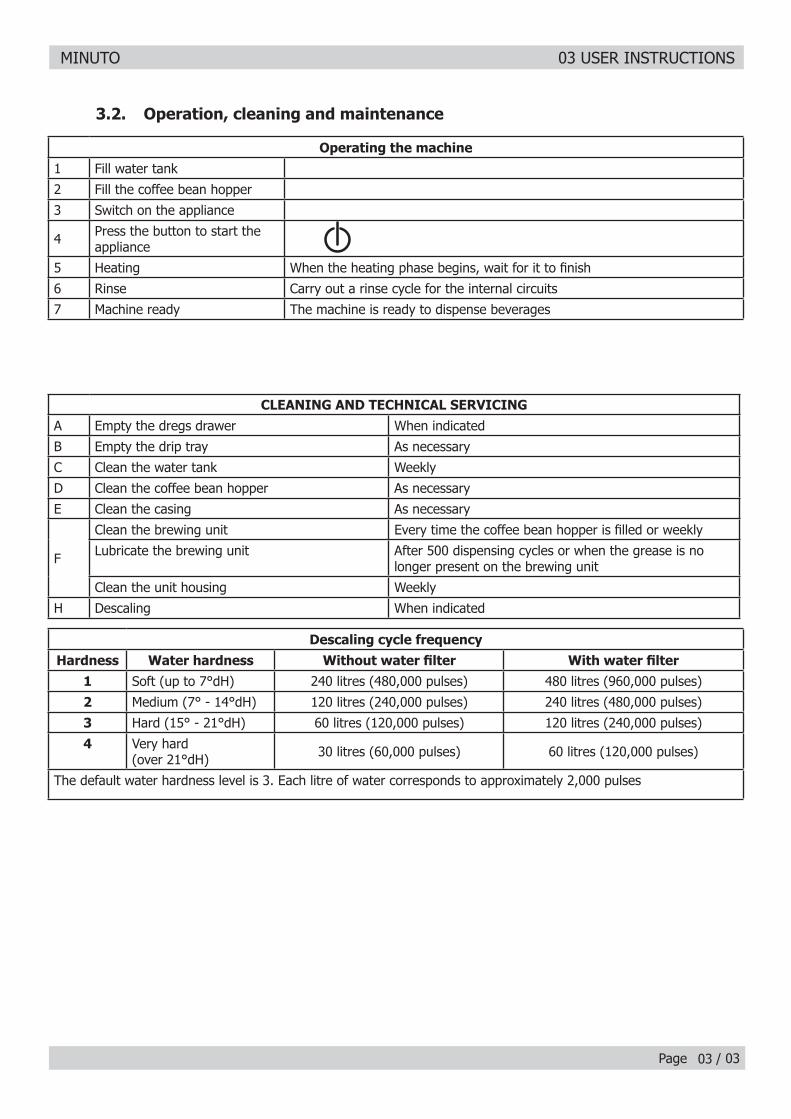
CLEANING AND TECHNICAL SERVICINGA Empty the dregs drawer When indicated
B Empty the drip tray As necessary
C Clean the water tank Weekly
D Clean the coffee bean hopper As necessary
E Clean the casing As necessary
F
Clean the brewing unit Every time the coffee bean hopper is fi lled or weekly
Lubricate the brewing unit After 500 dispensing cycles or when the grease is no longer present on the brewing unit
Clean the unit housing Weekly
H Descaling When indicated
Descaling cycle frequencyHardness Water hardness Without water fi lter With water fi lter
1 Soft (up to 7°dH) 240 litres (480,000 pulses) 480 litres (960,000 pulses)
2 Medium (7° - 14°dH) 120 litres (240,000 pulses) 240 litres (480,000 pulses)
3 Hard (15° - 21°dH) 60 litres (120,000 pulses) 120 litres (240,000 pulses)
4 Very hard (over 21°dH) 30 litres (60,000 pulses) 60 litres (120,000 pulses)
The default water hardness level is 3. Each litre of water corresponds to approximately 2,000 pulses
3.2. Operation, cleaning and maintenance
Operating the machine1 Fill water tank
2 Fill the coffee bean hopper
3 Switch on the appliance
4 Press the button to start the appliance
5 Heating When the heating phase begins, wait for it to fi nish
6 Rinse Carry out a rinse cycle for the internal circuits
7 Machine ready The machine is ready to dispense beverages
03
MINUTO
CHAPTER 4 OPERATING LOGIC
MINUTO 04 OPERATING LOGIC
Page / 0701
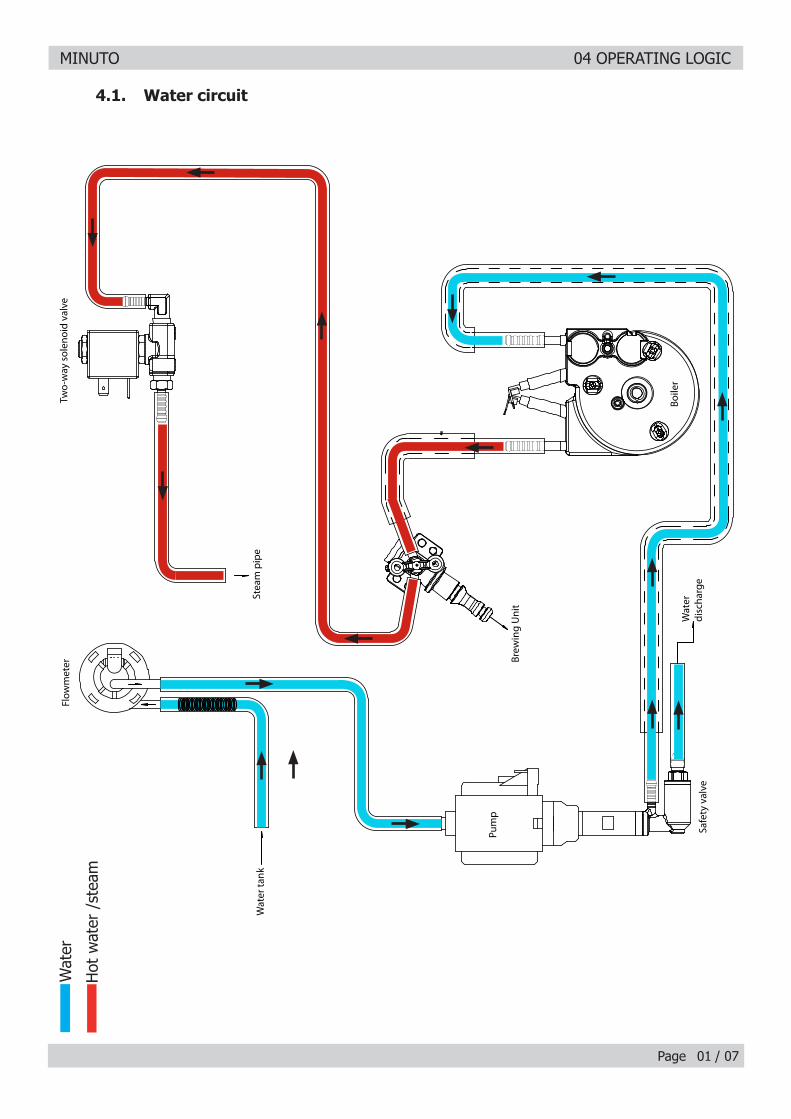
4.1. Water circuit
Wat
er
Hot
wat
er /
stea
m
Pu
mp
Sa
fety
va
lve
Wa
ter
dis
cha
rge
Ste
am
pip
eW
ate
r ta
nk
Tw
o-w
ay
so
len
oid
va
lve
Bre
win
g U
nit
Flo
wm
ete
r
Bo
ile
r
MINUTO 04 OPERATING LOGIC
Page / 07
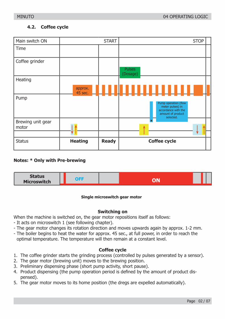
Notes: * Only with Pre-brewing
4.2. Coffee cycle
Switching onWhen the machine is switched on, the gear motor repositions itself as follows:- It acts on microswitch 1 (see following chapter).- The gear motor changes its rotation direction and moves upwards again by approx. 1-2 mm.- The boiler begins to heat the water for approx. 45 sec., at full power, in order to reach the
optimal temperature. The temperature will then remain at a constant level.
Coffee cycle1. The coffee grinder starts the grinding process (controlled by pulses generated by a sensor).2. The gear motor (brewing unit) moves to the brewing position.3. Preliminary dispensing phase (short pump activity, short pause).4. Product dispensing (the pump operation period is defi ned by the amount of product dis-
pensed).5. The gear motor moves to its home position (the dregs are expelled automatically).
Main switch ON START STOP
Time
Coffee grinder
Heating
Pump
Brewing unit gear motor
Status Heating Ready Coffee cycle
Pulses (Dosage)
Pump operation (fl ow meter pulses) in
accordance with the amount of product
selected.
approx. 45 sec.
*
02
Single microswitch gear motor
StatusMicroswitch OFF ON
MINUTO 04 OPERATING LOGIC
Page / 07
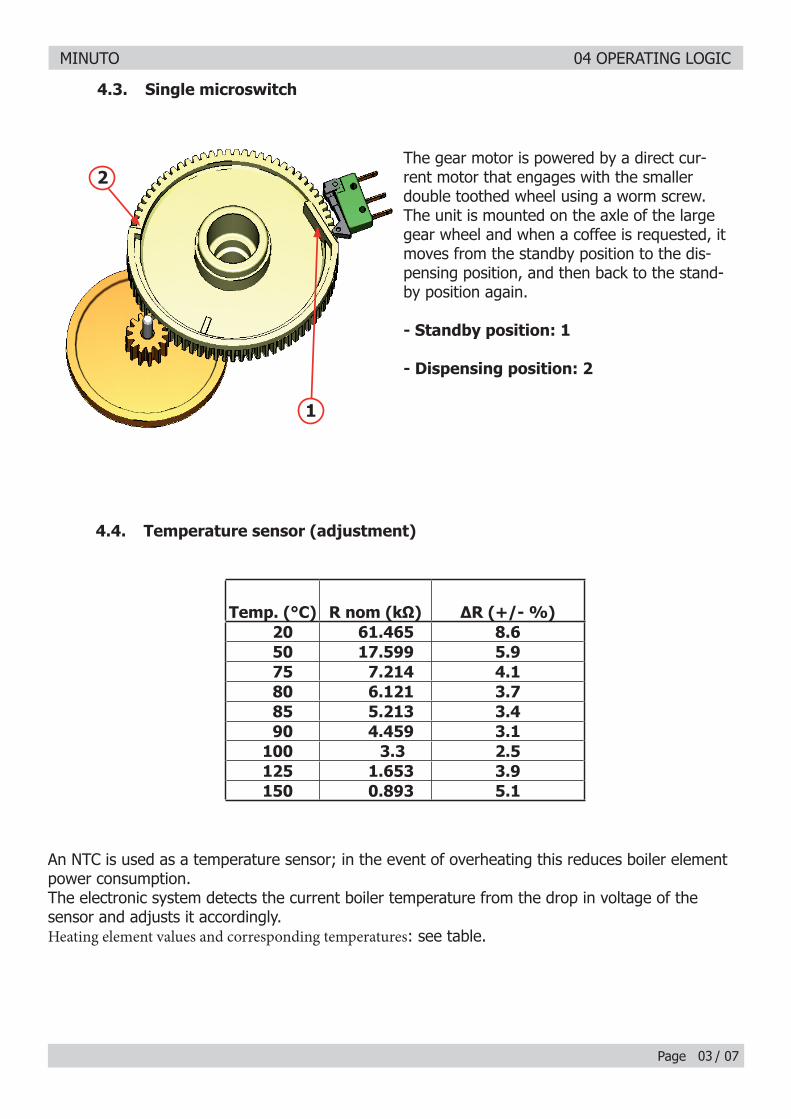
An NTC is used as a temperature sensor; in the event of overheating this reduces boiler element power consumption.The electronic system detects the current boiler temperature from the drop in voltage of the sensor and adjusts it accordingly.Heating element values and corresponding temperatures: see table.
4.4. Temperature sensor (adjustment)
Temp. (°C) R nom (kΩ) ΔR (+/- %)20 61.465 8.650 17.599 5.975 7.214 4.180 6.121 3.785 5.213 3.490 4.459 3.1
100 3.3 2.5125 1.653 3.9150 0.893 5.1
4.3. Single microswitch
The gear motor is powered by a direct cur-rent motor that engages with the smaller double toothed wheel using a worm screw. The unit is mounted on the axle of the large gear wheel and when a coffee is requested, it moves from the standby position to the dis-pensing position, and then back to the stand-by position again.
- Standby position: 1
- Dispensing position: 2
2
1
03

MINUTO 04 OPERATING LOGIC
Page / 07
4.5. Coffee grinder
23
4
5
6
1
4.6. Low bean level detection, dose quantity adjustment, coffee grinder blocked
t1V
t2
t3
t4
t
Without beans n=100%
With beans n=100%
Without beans n=50%
With beans n=50%
The coffee grinder is driven by a direct current motor (1) using a worm screw helicoidal wheel transmission (2).The worm screw (2) drives a plastic gear wheel (3), which turns the lower grinder (4) and the increment pin (5) There are two magnets (6) in the gear wheel; at every rotation these induce two pulses to a Hall sensor, which in turn transmits them to the electronic system.
No coffeeA low coffee bean level is detected by the Hall sensor, after variations in the pulse frequency (with or without coffee). If there are no coffee beans (operation while empty), the number of rotations – and therefore the number of pulses – will be greater.t1 = no coffee indication
If, however, there are coffee beans, the number of rotations will be lower due to the force created by the grinding.t2 = no indication
t3 and t4 = this measurement is performed at the end of each grinding process
Dose quantity adjustmentThe dose quantity is adjusted in accordance with the pulses detected (number of rotations proportional to the selected fl avor – mild, medium or strong).Coffee grinder blockageIf the coffee grinder becomes blocked for any reason, pulses will no longer be transmitted to the electronic system and the grinder will come to a stop.
04
MINUTO 04 OPERATING LOGIC
Page / 07
4.7. Dose self-learning (SAS)
05
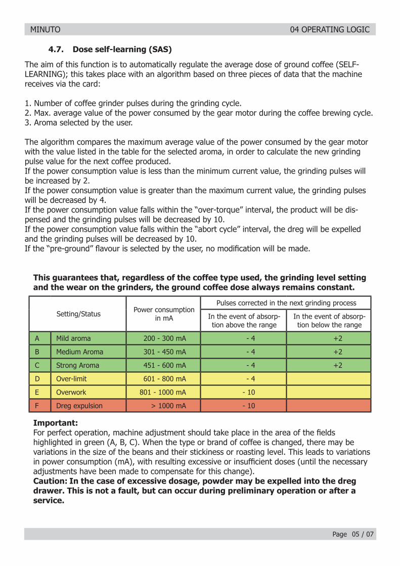
The aim of this function is to automatically regulate the average dose of ground coffee (SELF-LEARNING); this takes place with an algorithm based on three pieces of data that the machine receives via the card:
1. Number of coffee grinder pulses during the grinding cycle.2. Max. average value of the power consumed by the gear motor during the coffee brewing cycle.3. Aroma selected by the user.
The algorithm compares the maximum average value of the power consumed by the gear motor with the value listed in the table for the selected aroma, in order to calculate the new grinding pulse value for the next coffee produced.If the power consumption value is less than the minimum current value, the grinding pulses will be increased by 2.If the power consumption value is greater than the maximum current value, the grinding pulses will be decreased by 4.If the power consumption value falls within the “over-torque” interval, the product will be dis-pensed and the grinding pulses will be decreased by 10.If the power consumption value falls within the “abort cycle” interval, the dreg will be expelled and the grinding pulses will be decreased by 10.If the “pre-ground” fl avour is selected by the user, no modifi cation will be made.
This guarantees that, regardless of the coffee type used, the grinding level setting and the wear on the grinders, the ground coffee dose always remains constant.
Important:For perfect operation, machine adjustment should take place in the area of the fi elds highlighted in green (A, B, C). When the type or brand of coffee is changed, there may be variations in the size of the beans and their stickiness or roasting level. This leads to variations in power consumption (mA), with resulting excessive or insuffi cient doses (until the necessary adjustments have been made to compensate for this change).Caution: In the case of excessive dosage, powder may be expelled into the dreg drawer. This is not a fault, but can occur during preliminary operation or after a service.
Setting/Status Power consumption in mA
Pulses corrected in the next grinding process
In the event of absorp-tion above the range
In the event of absorp-tion below the range
A Mild aroma 200 - 300 mA - 4 +2
B Medium Aroma 301 - 450 mA - 4 +2
C Strong Aroma 451 - 600 mA - 4 +2
D Over-limit 601 - 800 mA - 4
E Overwork 801 - 1000 mA - 10
F Dreg expulsion > 1000 mA - 10
MINUTO 04 OPERATING LOGIC
Page / 07
4.8. Water level detection (water tank)
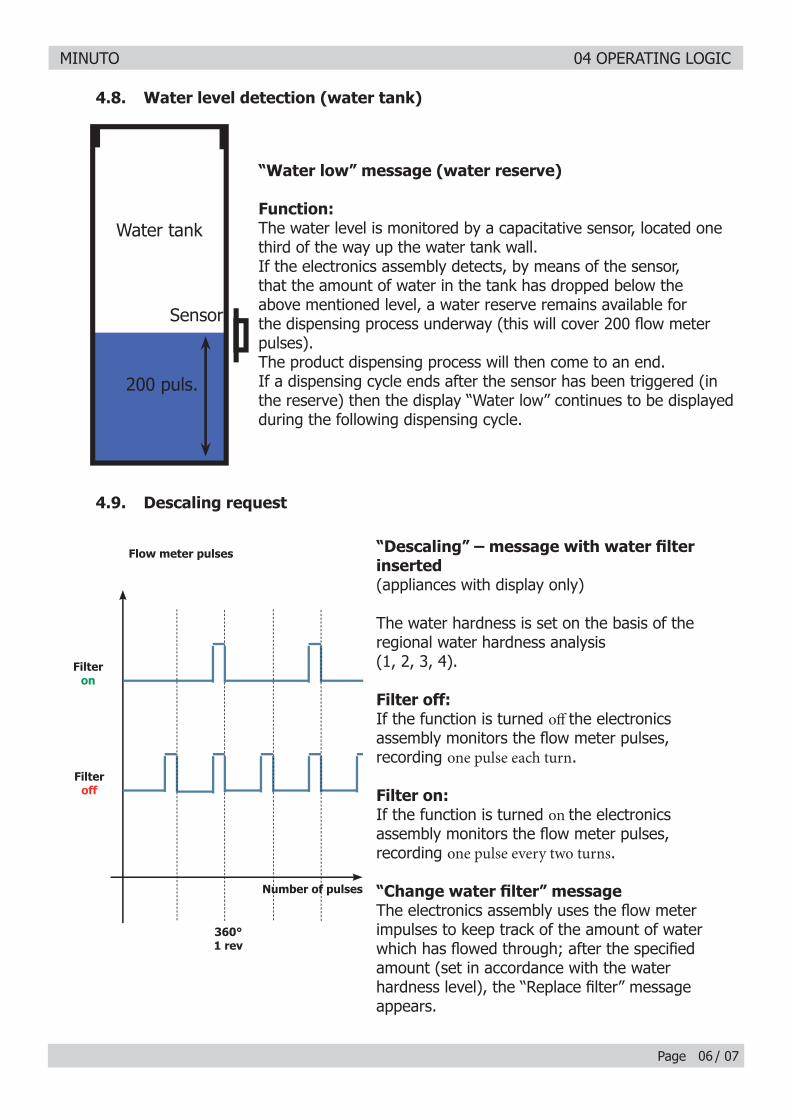
“Water low” message (water reserve)
Function:The water level is monitored by a capacitative sensor, located one third of the way up the water tank wall.If the electronics assembly detects, by means of the sensor, that the amount of water in the tank has dropped below the above mentioned level, a water reserve remains available for the dispensing process underway (this will cover 200 fl ow meter pulses).The product dispensing process will then come to an end.If a dispensing cycle ends after the sensor has been triggered (in the reserve) then the display “Water low” continues to be displayed during the following dispensing cycle.
200 puls.
Sensor
Water tank
06
“Descaling” – message with water fi lter inserted(appliances with display only)
The water hardness is set on the basis of the regional water hardness analysis (1, 2, 3, 4).
Filter off:If the function is turned off the electronics assembly monitors the fl ow meter pulses, recording one pulse each turn.
Filter on:If the function is turned on the electronics assembly monitors the fl ow meter pulses, recording one pulse every two turns.
“Change water fi lter” message The electronics assembly uses the fl ow meter impulses to keep track of the amount of water which has fl owed through; after the specifi ed amount (set in accordance with the water hardness level), the “Replace fi lter” message appears.
4.9. Descaling request
360°1 rev
Number of pulses
Filteron
Filteroff
Flow meter pulses
MINUTO 04 OPERATING LOGIC
Page / 07
Bypass
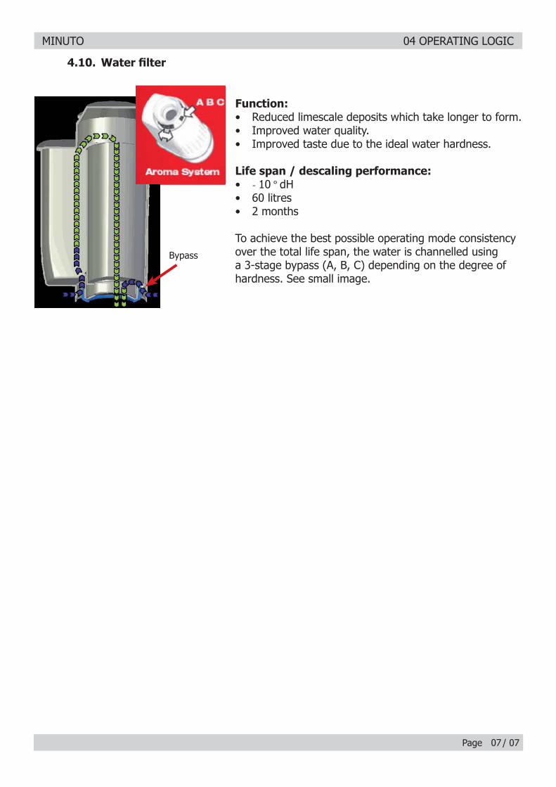
4.10. Water fi lter
07
Function:• Reduced limescale deposits which take longer to form.• Improved water quality.• Improved taste due to the ideal water hardness.
Life span / descaling performance:• - 10 ° dH• 60 litres• 2 months
To achieve the best possible operating mode consistency over the total life span, the water is channelled using a 3-stage bypass (A, B, C) depending on the degree of hardness. See small image.

MINUTO
CHAPTER 5 TROUBLESHOOTING
MINUTO 05 TROUBLESHOOTING
Page / 08
5.1.1. Minuto test mode
01
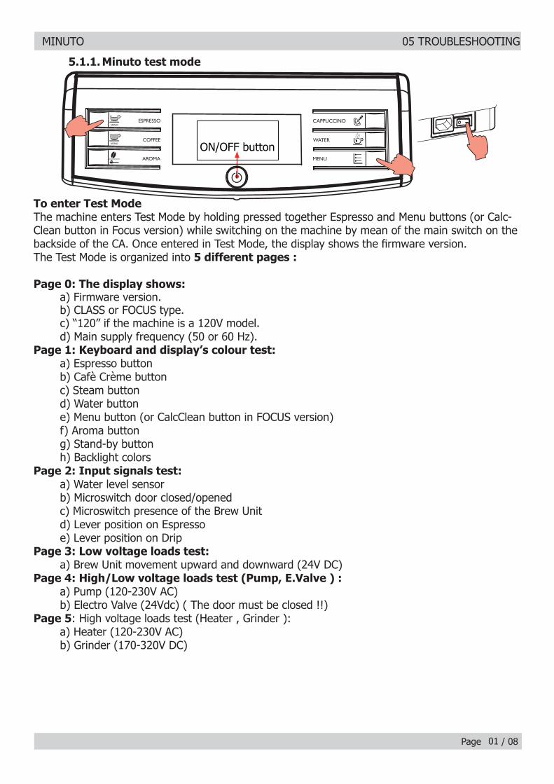
To enter Test Mode The machine enters Test Mode by holding pressed together Espresso and Menu buttons (or Calc-Clean button in Focus version) while switching on the machine by mean of the main switch on the backside of the CA. Once entered in Test Mode, the display shows the fi rmware version.The Test Mode is organized into 5 different pages :
Page 0: The display shows:a) Firmware version.b) CLASS or FOCUS type.c) “120” if the machine is a 120V model.d) Main supply frequency (50 or 60 Hz).
Page 1: Keyboard and display’s colour test:a) Espresso buttonb) Cafè Crème buttonc) Steam buttond) Water buttone) Menu button (or CalcClean button in FOCUS version)f) Aroma buttong) Stand-by buttonh) Backlight colors
Page 2: Input signals test:a) Water level sensorb) Microswitch door closed/openedc) Microswitch presence of the Brew Unitd) Lever position on Espressoe) Lever position on Drip
Page 3: Low voltage loads test:a) Brew Unit movement upward and downward (24V DC)
Page 4: High/Low voltage loads test (Pump, E.Valve ) :a) Pump (120-230V AC)b) Electro Valve (24Vdc) ( The door must be closed !!)
Page 5: High voltage loads test (Heater , Grinder ):a) Heater (120-230V AC)b) Grinder (170-320V DC)
ON/OFF button
MINUTO 05 TROUBLESHOOTING
Page / 0802
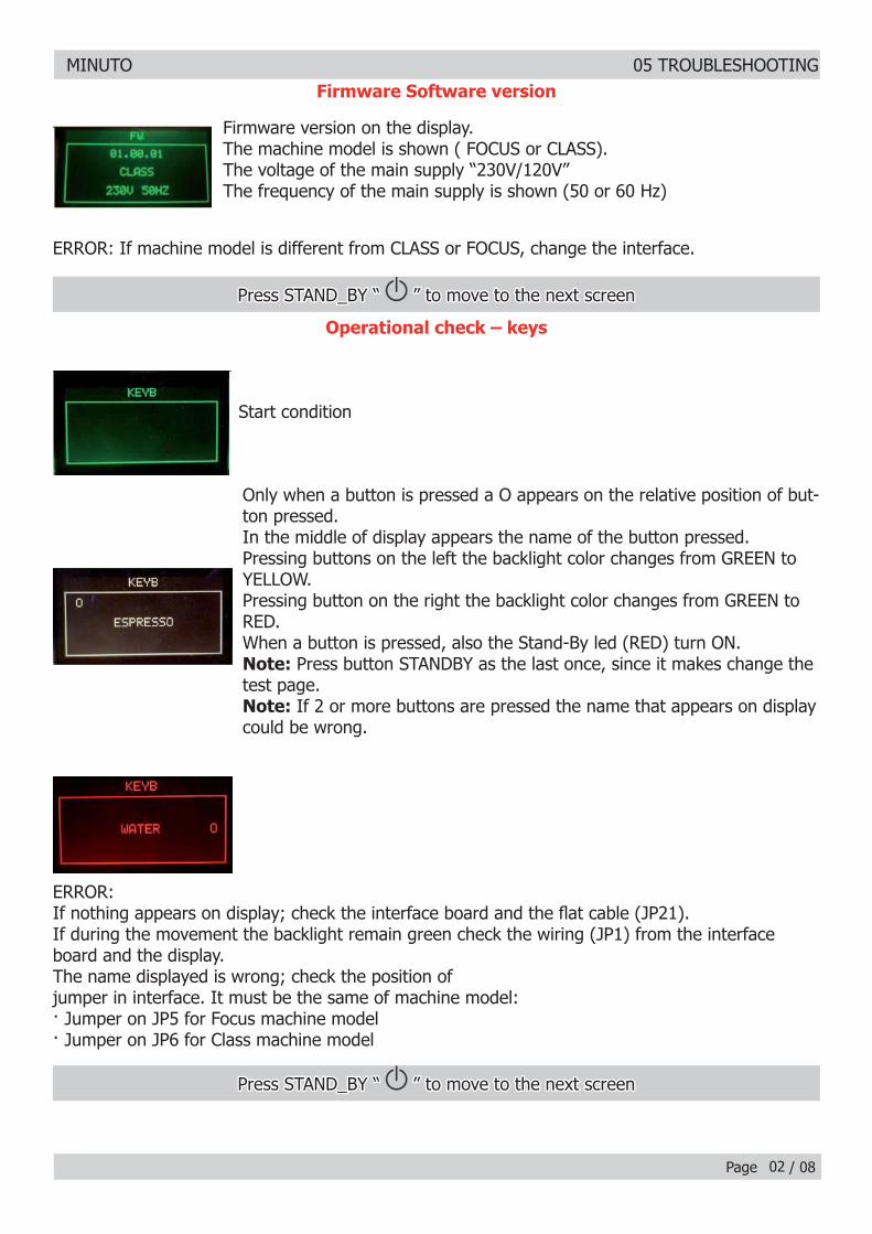
Firmware Software versionFirmware Software version
Firmware version on the display.Firmware version on the display.The machine model is shown ( FOCUS or CLASS).The machine model is shown ( FOCUS or CLASS).The voltage of the main supply “230V/120V”The voltage of the main supply “230V/120V”The frequency of the main supply is shown (50 or 60 Hz)The frequency of the main supply is shown (50 or 60 Hz)
ERROR: If machine model is different from CLASS or FOCUS, change the interface.ERROR: If machine model is different from CLASS or FOCUS, change the interface.
Only when a button is pressed a O appears on the relative position of but-Only when a button is pressed a O appears on the relative position of but-ton pressed.ton pressed.In the middle of display appears the name of the button pressed.In the middle of display appears the name of the button pressed.Pressing buttons on the left the backlight color changes from GREEN to Pressing buttons on the left the backlight color changes from GREEN to YELLOW.YELLOW.Pressing button on the right the backlight color changes from GREEN to Pressing button on the right the backlight color changes from GREEN to RED.RED.When a button is pressed, also the Stand-By led (RED) turn ON.When a button is pressed, also the Stand-By led (RED) turn ON.Note:Note: Press button STANDBY as the last once, since it makes change the Press button STANDBY as the last once, since it makes change the test page.test page.Note:Note: If 2 or more buttons are pressed the name that appears on display If 2 or more buttons are pressed the name that appears on display could be wrong.could be wrong.
ERROR: ERROR: If nothing appears on display; check the interface board and the fl at cable (JP21).If nothing appears on display; check the interface board and the fl at cable (JP21).If during the movement the backlight remain green check the wiring (JP1) from the interface board and the display.The name displayed is wrong; check the position ofjumper in interface. It must be the same of machine model:· Jumper on JP5 for Focus machine model· Jumper on JP6 for Class machine model
Start conditionStart condition
Operational check – keysOperational check – keys
Press STAND_BY “ Press STAND_BY “ ” to move to the next screen ” to move to the next screen
Press STAND_BY “ Press STAND_BY “ ” to move to the next screen ” to move to the next screen
MINUTO 05 TROUBLESHOOTING
Page / 0803
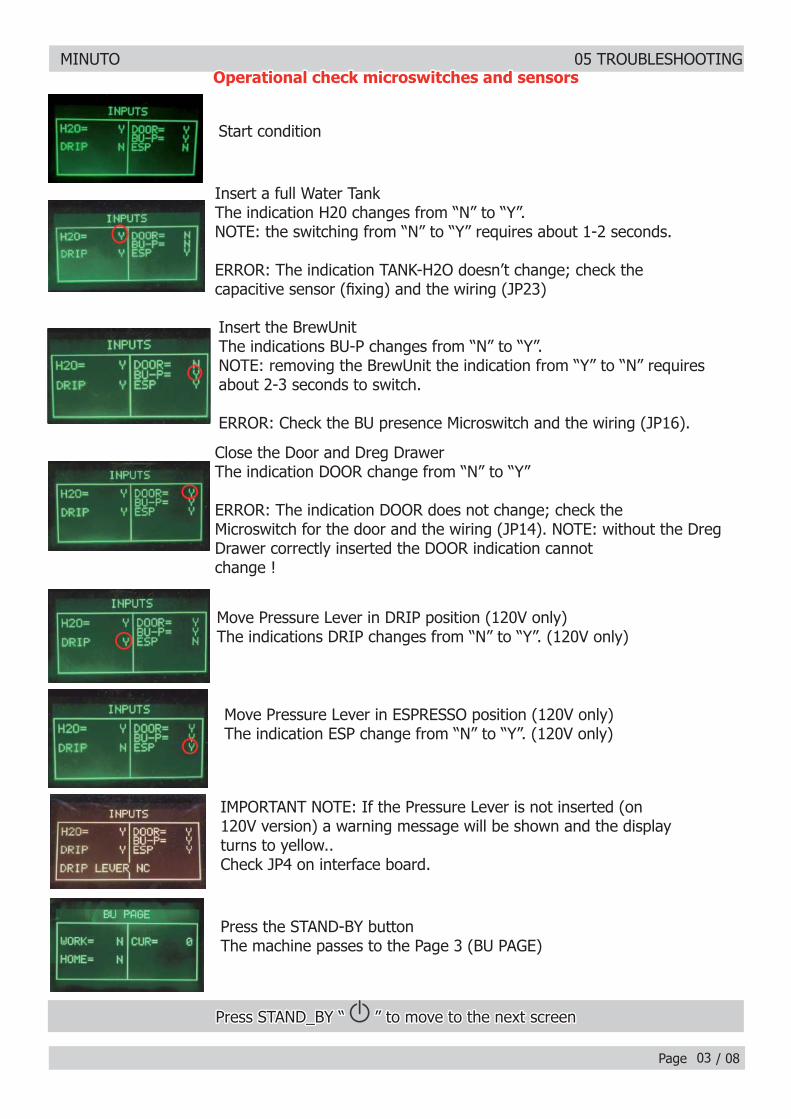
Insert a full Water TankInsert a full Water TankThe indication H20 changes from “N” to “Y”.NOTE: the switching from “N” to “Y” requires about 1-2 seconds.
ERROR: The indication TANK-H2O doesn’t change; check thecapacitive sensor (fi xing) and the wiring (JP23)
Insert the BrewUnitInsert the BrewUnitThe indications BU-P changes from “N” to “Y”.The indications BU-P changes from “N” to “Y”.NOTE: removing the BrewUnit the indication from “Y” to “N” requires NOTE: removing the BrewUnit the indication from “Y” to “N” requires about 2-3 seconds to switch.about 2-3 seconds to switch.
ERROR: Check the BU presence Microswitch and the wiring (JP16).ERROR: Check the BU presence Microswitch and the wiring (JP16).
Close the Door and Dreg DrawerClose the Door and Dreg DrawerThe indication DOOR change from “N” to “Y”The indication DOOR change from “N” to “Y”
ERROR: The indication DOOR does not change; check theERROR: The indication DOOR does not change; check theMicroswitch for the door and the wiring (JP14). NOTE: without the Dreg Microswitch for the door and the wiring (JP14). NOTE: without the Dreg Drawer correctly inserted the DOOR indication cannotDrawer correctly inserted the DOOR indication cannotchange !change !
Move Pressure Lever in DRIP position (120V only)Move Pressure Lever in DRIP position (120V only)The indications DRIP changes from “N” to “Y”. (120V only)The indications DRIP changes from “N” to “Y”. (120V only)
Move Pressure Lever in ESPRESSO position (120V only)Move Pressure Lever in ESPRESSO position (120V only)The indication ESP change from “N” to “Y”. (120V only)The indication ESP change from “N” to “Y”. (120V only)
IMPORTANT NOTE: If the Pressure Lever is not inserted (onIMPORTANT NOTE: If the Pressure Lever is not inserted (on120V version) a warning message will be shown and the display120V version) a warning message will be shown and the displayturns to yellow..turns to yellow..Check JP4 on interface board.Check JP4 on interface board.
Press the STAND-BY button Press the STAND-BY button The machine passes to the Page 3 (BU PAGE)
Start conditionStart condition
Press STAND_BY “ Press STAND_BY “ ” to move to the next screen ” to move to the next screen
Operational check microswitches and sensorsOperational check microswitches and sensors
MINUTO 05 TROUBLESHOOTING
Page / 0804
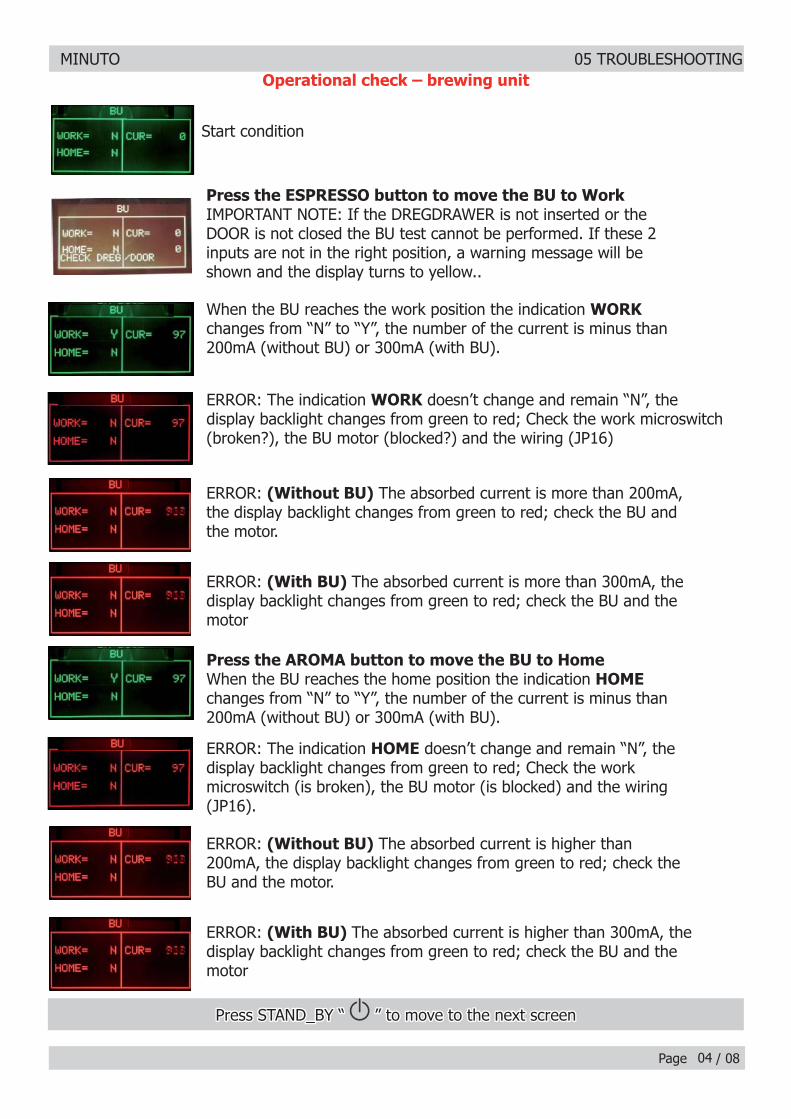
Start conditionStart condition
Press the ESPRESSO button to move the BU to Work Press the ESPRESSO button to move the BU to Work IMPORTANT NOTE: If the DREGDRAWER is not inserted or theIMPORTANT NOTE: If the DREGDRAWER is not inserted or theDOOR is not closed the BU test cannot be performed. If these 2DOOR is not closed the BU test cannot be performed. If these 2inputs are not in the right position, a warning message will beinputs are not in the right position, a warning message will beshown and the display turns to yellow..shown and the display turns to yellow..
When the BU reaches the work position the indication When the BU reaches the work position the indication WORKWORKchanges from “N” to “Y”, the number of the current is minus thanchanges from “N” to “Y”, the number of the current is minus than200mA (without BU) or 300mA (with BU).200mA (without BU) or 300mA (with BU).
ERROR: The indication ERROR: The indication WORKWORK doesn’t change and remain “N”, the doesn’t change and remain “N”, thedisplay backlight changes from green to red; Check the work microswitch display backlight changes from green to red; Check the work microswitch (broken?), the BU motor (blocked?) and the wiring (JP16)(broken?), the BU motor (blocked?) and the wiring (JP16)
ERROR: ERROR: (Without BU)(Without BU) The absorbed current is more than 200mA, The absorbed current is more than 200mA,the display backlight changes from green to red; check the BU andthe display backlight changes from green to red; check the BU andthe motor.the motor.
ERROR: ERROR: (With BU) (With BU) The absorbed current is more than 300mA, theThe absorbed current is more than 300mA, thedisplay backlight changes from green to red; check the BU and thedisplay backlight changes from green to red; check the BU and themotormotor
Press the AROMA button to move the BU to HomePress the AROMA button to move the BU to Home When the BU reaches the home position the indication When the BU reaches the home position the indication HOMEHOMEchanges from “N” to “Y”, the number of the current is minus thanchanges from “N” to “Y”, the number of the current is minus than200mA (without BU) or 300mA (with BU). 200mA (without BU) or 300mA (with BU).
ERROR: The indication ERROR: The indication HOMEHOME doesn’t change and remain “N”, the doesn’t change and remain “N”, thedisplay backlight changes from green to red; Check the workdisplay backlight changes from green to red; Check the workmicroswitch (is broken), the BU motor (is blocked) and the wiringmicroswitch (is broken), the BU motor (is blocked) and the wiring(JP16).(JP16).
ERROR: ERROR: (Without BU)(Without BU) The absorbed current is higher than The absorbed current is higher than200mA, the display backlight changes from green to red; check the200mA, the display backlight changes from green to red; check theBU and the motor.BU and the motor.
ERROR: ERROR: (With BU) (With BU) The absorbed current is higher than 300mA, theThe absorbed current is higher than 300mA, thedisplay backlight changes from green to red; check the BU and thedisplay backlight changes from green to red; check the BU and themotormotor
Operational check – brewing unit
Press STAND_BY “ Press STAND_BY “ ” to move to the next screen ” to move to the next screen
MINUTO 05 TROUBLESHOOTING
Page / 08
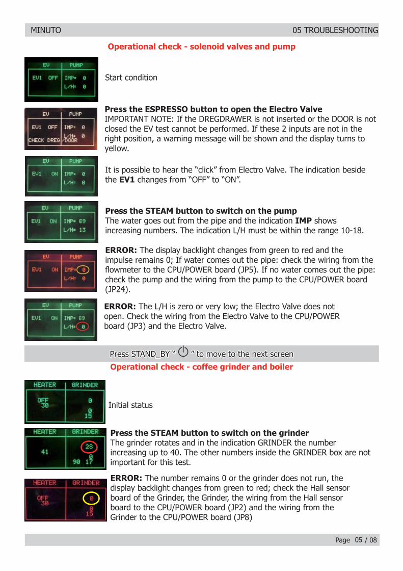
Start conditionStart condition
Press the ESPRESSO button to open the Electro ValvePress the ESPRESSO button to open the Electro Valve IMPORTANT NOTE: If the DREGDRAWER is not inserted or the DOOR is not IMPORTANT NOTE: If the DREGDRAWER is not inserted or the DOOR is not closed the EV test cannot be performed. If these 2 inputs are not in the closed the EV test cannot be performed. If these 2 inputs are not in the right position, a warning message will be shown and the display turns to right position, a warning message will be shown and the display turns to yellow.yellow.
Press the STEAM button to switch on the pumpPress the STEAM button to switch on the pumpThe water goes out from the pipe and the indication The water goes out from the pipe and the indication IMPIMP shows showsincreasing numbers. The indication L/H must be within the range 10-18.increasing numbers. The indication L/H must be within the range 10-18.
It is possible to hear the “click” from Electro Valve. The indication beside It is possible to hear the “click” from Electro Valve. The indication beside the the EV1EV1 changes from “OFF” to “ON”. changes from “OFF” to “ON”.
ERROR:ERROR: The display backlight changes from green to red and the The display backlight changes from green to red and the impulse remains 0; If water comes out the pipe: check the wiring from the impulse remains 0; If water comes out the pipe: check the wiring from the fl owmeter to the CPU/POWER board (JP5). If no water comes out the pipe: fl owmeter to the CPU/POWER board (JP5). If no water comes out the pipe: check the pump and the wiring from the pump to the CPU/POWER board check the pump and the wiring from the pump to the CPU/POWER board (JP24).(JP24).
ERROR:ERROR: The L/H is zero or very low; the Electro Valve does not The L/H is zero or very low; the Electro Valve does notopen. Check the wiring from the Electro Valve to the CPU/POWERopen. Check the wiring from the Electro Valve to the CPU/POWERboard (JP3) and the Electro Valve.board (JP3) and the Electro Valve.
Press the STEAM button to switch on the grinderPress the STEAM button to switch on the grinderThe grinder rotates and in the indication GRINDER the numberincreasing up to 40. The other numbers inside the GRINDER box are not important for this test.
ERROR:ERROR: The number remains 0 or the grinder does not run, the The number remains 0 or the grinder does not run, thedisplay backlight changes from green to red; check the Hall sensordisplay backlight changes from green to red; check the Hall sensorboard of the Grinder, the Grinder, the wiring from the Hall sensorboard of the Grinder, the Grinder, the wiring from the Hall sensorboard to the CPU/POWER board (JP2) and the wiring from theboard to the CPU/POWER board (JP2) and the wiring from theGrinder to the CPU/POWER board (JP8)Grinder to the CPU/POWER board (JP8)
Initial statusInitial status
05
Operational check - solenoid valves and pump
Press STAND_BY “ Press STAND_BY “ ” to move to the next screen ” to move to the next screen
Operational check - coffee grinder and boiler
MINUTO 05 TROUBLESHOOTING
Page / 0806
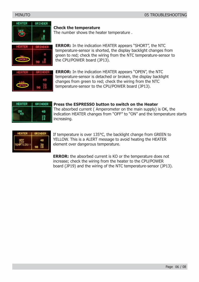
Check the temperatureCheck the temperatureThe number shows the heater temperature .The number shows the heater temperature .
ERROR:ERROR: In the indication HEATER appears “SHORT”, the NTC In the indication HEATER appears “SHORT”, the NTCtemperature-sensor is shorted, the display backlight changes fromtemperature-sensor is shorted, the display backlight changes fromgreen to red; check the wiring from the NTC temperature-sensor togreen to red; check the wiring from the NTC temperature-sensor tothe CPU/POWER board (JP13).the CPU/POWER board (JP13).
ERROR:ERROR: In the indication HEATER appears “OPEN”, the NTC In the indication HEATER appears “OPEN”, the NTCtemperature-sensor is detached or broken, the display backlighttemperature-sensor is detached or broken, the display backlightchanges from green to red; check the wiring from the NTCchanges from green to red; check the wiring from the NTCtemperature-sensor to the CPU/POWER board (JP13).temperature-sensor to the CPU/POWER board (JP13).
Press the ESPRESSO button to switch on the HeaterPress the ESPRESSO button to switch on the HeaterThe absorbed current ( Amperometer on the main supply) is OK, theThe absorbed current ( Amperometer on the main supply) is OK, theindication HEATER changes from “OFF” to “ON” and the temperature starts indication HEATER changes from “OFF” to “ON” and the temperature starts increasing.increasing.
If temperature is over 135°C, the backlight change from GREEN toIf temperature is over 135°C, the backlight change from GREEN toYELLOW. This is a ALERT message to avoid heating the HEATERYELLOW. This is a ALERT message to avoid heating the HEATERelement over dangerous temperature.element over dangerous temperature.
ERROR:ERROR: the absorbed current is KO or the temperature does not the absorbed current is KO or the temperature does notincrease; check the wiring from the heater to the CPU/POWERincrease; check the wiring from the heater to the CPU/POWERboard (JP19) and the wiring of the NTC temperature-sensor (JP13).board (JP19) and the wiring of the NTC temperature-sensor (JP13).
MINUTO 05 TROUBLESHOOTING
Page / 08
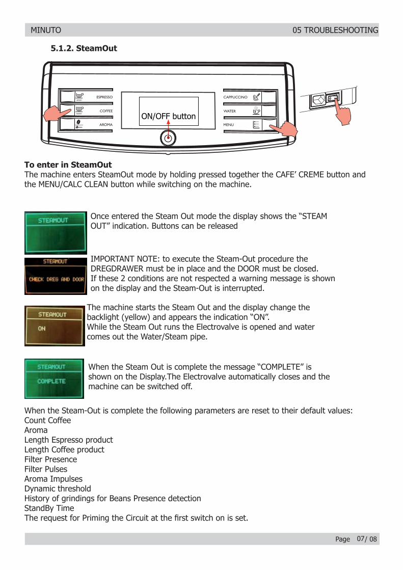
Once entered the Steam Out mode the display shows the “STEAMOnce entered the Steam Out mode the display shows the “STEAMOUT” indication. Buttons can be releasedOUT” indication. Buttons can be released
IMPORTANT NOTE: to execute the Steam-Out procedure theIMPORTANT NOTE: to execute the Steam-Out procedure theDREGDRAWER must be in place and the DOOR must be closed.DREGDRAWER must be in place and the DOOR must be closed.If these 2 conditions are not respected a warning message is shownIf these 2 conditions are not respected a warning message is shownon the display and the Steam-Out is interrupted.on the display and the Steam-Out is interrupted.
The machine starts the Steam Out and the display change theThe machine starts the Steam Out and the display change thebacklight (yellow) and appears the indication “ON”.backlight (yellow) and appears the indication “ON”.While the Steam Out runs the Electrovalve is opened and waterWhile the Steam Out runs the Electrovalve is opened and watercomes out the Water/Steam pipe.comes out the Water/Steam pipe.
When the Steam Out is complete the message “COMPLETE” isWhen the Steam Out is complete the message “COMPLETE” isshown on the Display.The Electrovalve automatically closes and theshown on the Display.The Electrovalve automatically closes and themachine can be switched off.machine can be switched off.
When the Steam-Out is complete the following parameters are reset to their default values:When the Steam-Out is complete the following parameters are reset to their default values:Count CoffeeCount CoffeeAromaAromaLength Espresso productLength Espresso productLength Coffee productLength Coffee productFilter PresenceFilter PresenceFilter PulsesFilter PulsesAroma ImpulsesAroma ImpulsesDynamic thresholdDynamic thresholdHistory of grindings for Beans Presence detectionHistory of grindings for Beans Presence detectionStandBy TimeStandBy TimeThe request for Priming the Circuit at the fi rst switch on is set.The request for Priming the Circuit at the fi rst switch on is set.
5.1.2. SteamOut
To enter in SteamOutThe machine enters SteamOut mode by holding pressed together the CAFE’ CREME button and the MENU/CALC CLEAN button while switching on the machine.
ON/OFF button
07
MINUTO 05 TROUBLESHOOTING
Page / 08
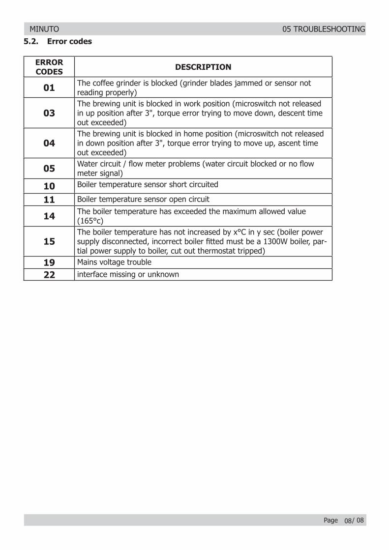
ERROR ERROR CODESCODES DESCRIPTIONDESCRIPTION
0101 The coffee grinder is blocked (grinder blades jammed or sensor not reading properly)
0303The brewing unit is blocked in work position (microswitch not released in up position after 3", torque error trying to move down, descent time out exceeded)
0404The brewing unit is blocked in home position (microswitch not released in down position after 3", torque error trying to move up, ascent time out exceeded)
0505 Water circuit / fl ow meter problems (water circuit blocked or no fl ow meter signal)
1010 Boiler temperature sensor short circuited
1111 Boiler temperature sensor open circuit
1414 The boiler temperature has exceeded the maximum allowed value (165°c)
1515The boiler temperature has not increased by x°C in y sec (boiler power supply disconnected, incorrect boiler fi tted must be a 1300W boiler, par-tial power supply to boiler, cut out thermostat tripped)
1919 Mains voltage trouble
2222 interface missing or unknown
5.2. Error codes
08
MINUTO
CHAPTER 6 STANDARD CHECKS
MINUTO 06 STANDARD CHECKS
Page / 0201
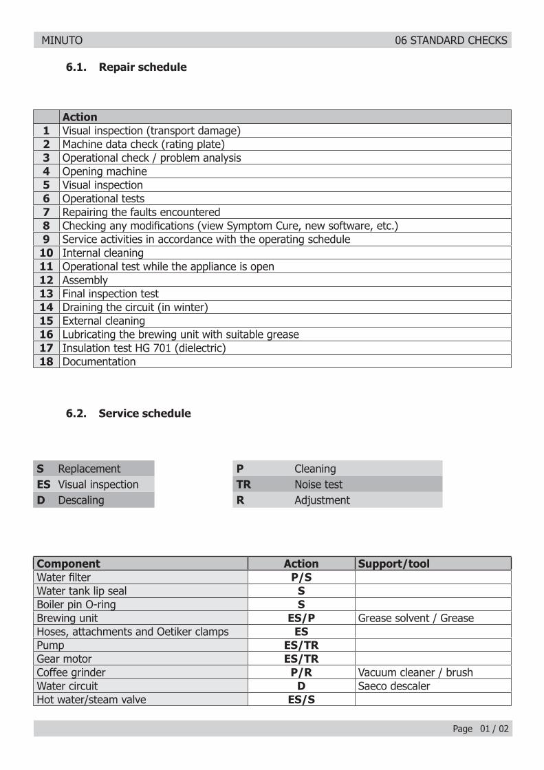
Action1 Visual inspection (transport damage)2 Machine data check (rating plate)3 Operational check / problem analysis4 Opening machine5 Visual inspection6 Operational tests7 Repairing the faults encountered8 Checking any modifi cations (view Symptom Cure, new software, etc.)9 Service activities in accordance with the operating schedule
10 Internal cleaning11 Operational test while the appliance is open12 Assembly13 Final inspection test14 Draining the circuit (in winter)15 External cleaning16 Lubricating the brewing unit with suitable grease17 Insulation test HG 701 (dielectric)18 Documentation
S Replacement P CleaningES Visual inspection TR Noise testD Descaling R Adjustment
Component Action Support/toolWater fi lter P/SWater tank lip seal SBoiler pin O-ring SBrewing unit ES/P Grease solvent / GreaseHoses, attachments and Oetiker clamps ESPump ES/TRGear motor ES/TRCoffee grinder P/R Vacuum cleaner / brushWater circuit D Saeco descalerHot water/steam valve ES/S
6.2. Service schedule
6.1. Repair schedule
MINUTO 06 STANDARD CHECKS
Page / 0202
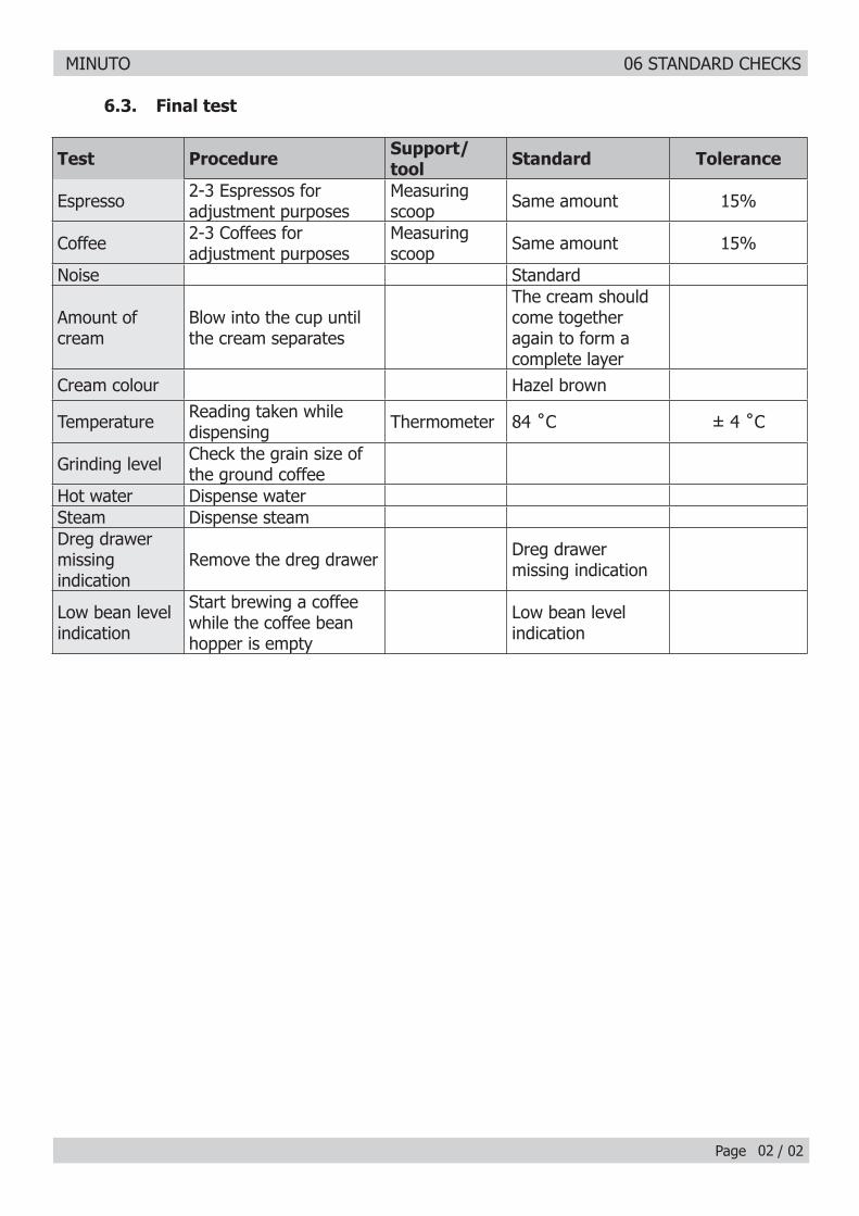
Test Procedure Support/tool Standard Tolerance
Espresso 2-3 Espressos for adjustment purposes
Measuring scoop Same amount 15%
Coffee 2-3 Coffees for adjustment purposes
Measuring scoop Same amount 15%
Noise Standard
Amount of cream
Blow into the cup until the cream separates
The cream should come together again to form a complete layer
Cream colour Hazel brown
Temperature Reading taken while dispensing Thermometer 84 ˚C ± 4 ˚C
Grinding level Check the grain size of the ground coffee
Hot water Dispense waterSteam Dispense steamDreg drawer missing indication
Remove the dreg drawer Dreg drawer missing indication
Low bean level indication
Start brewing a coffee while the coffee bean hopper is empty
Low bean level indication
6.3. Final test

MINUTO
CHAPTER 7 DISASSEMBLY
MINUTO 07 DISASSEMBLY
Page / 11
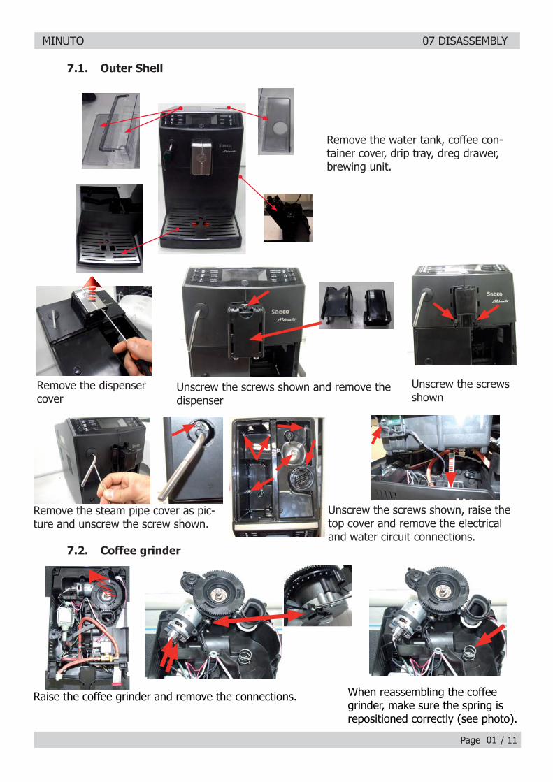
7.1. Outer Shell
Remove the water tank, coffee con-tainer cover, drip tray, dreg drawer, brewing unit.
Unscrew the screws shown and remove the dispenser
Unscrew the screws shown
Unscrew the screws shown, raise the top cover and remove the electrical and water circuit connections.
Remove the dispenser cover
Remove the steam pipe cover as pic-ture and unscrew the screw shown.
01
7.2. Coffee grinder
Raise the coffee grinder and remove the connections. When reassembling the coffee grinder, make sure the spring is repositioned correctly (see photo).
MINUTO 07 DISASSEMBLY
Page / 1102
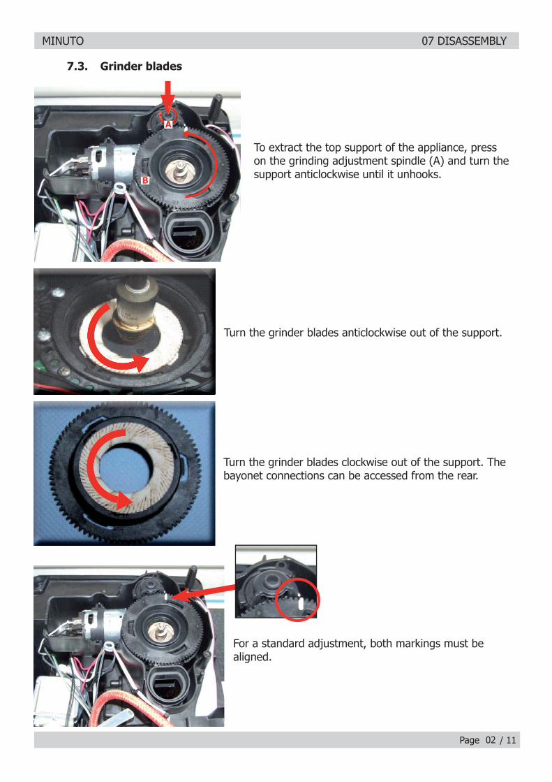
To extract the top support of the appliance, press on the grinding adjustment spindle (A) and turn the support anticlockwise until it unhooks.
Turn the grinder blades anticlockwise out of the support.
Turn the grinder blades clockwise out of the support. The bayonet connections can be accessed from the rear.
For a standard adjustment, both markings must be aligned.
7.3. Grinder blades
A
B
MINUTO 07 DISASSEMBLY
Page / 1103
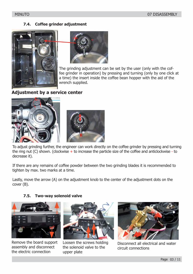
7.4. Coffee grinder adjustment
The grinding adjustment can be set by the user (only with the cof-fee grinder in operation) by pressing and turning (only by one click at a time) the insert inside the coffee bean hopper with the aid of the wrench supplied.
+
-
Adjustment by a service center
To adjust grinding further, the engineer can work directly on the coffee grinder by pressing and turning the ring nut (C) shown. (clockwise + to increase the particle size of the coffee and anticlockwise - to decrease it).
If there are any remains of coffee powder between the two grinding blades it is recommended to tighten by max. two marks at a time.
Lastly, move the arrow (A) on the adjustment knob to the center of the adjustment dots on the cover (B).
+-
C
A
B
Remove the board support assembly and disconnect the electric connection
Loosen the screws holding the solenoid valve to the upper plate
Disconnect all electrical and water circuit connections
7.5. Two-way solenoid valve
MINUTO 07 DISASSEMBLY
Page / 1104
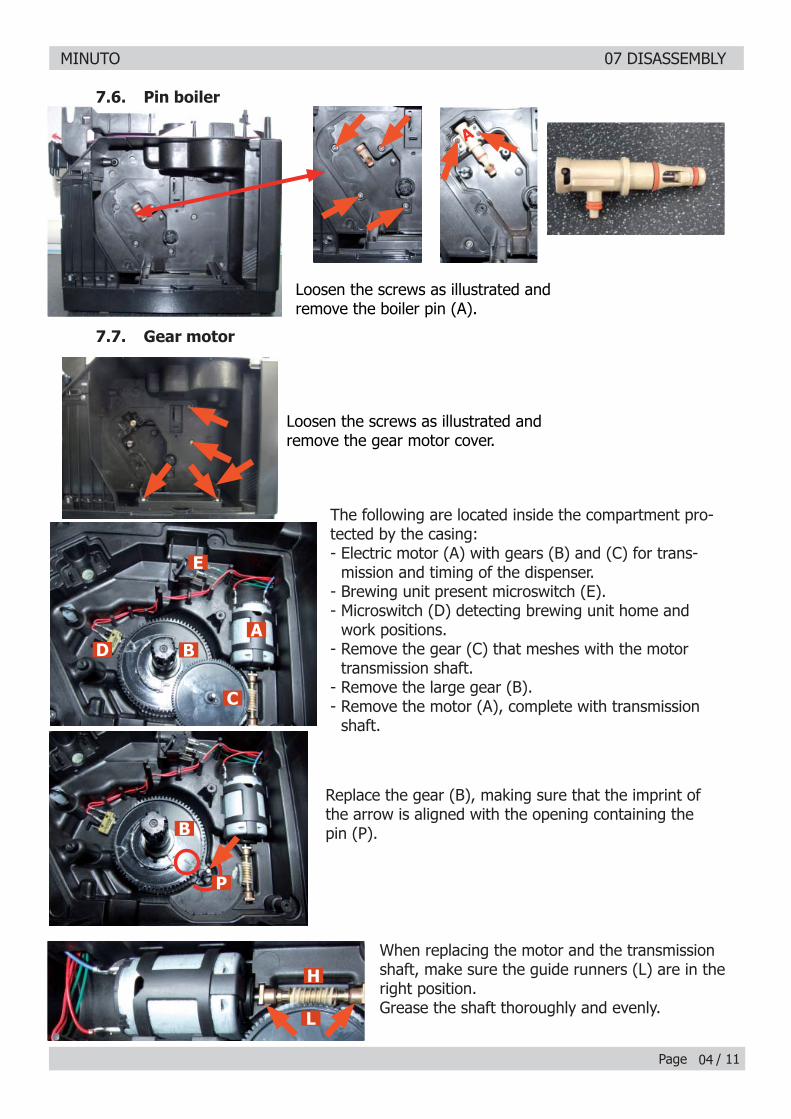
7.6. Pin boiler
7.7. Gear motor
Loosen the screws as illustrated and remove the boiler pin (A).
Loosen the screws as illustrated and remove the gear motor cover.
A
The following are located inside the compartment pro-tected by the casing:- Electric motor (A) with gears (B) and (C) for trans-
mission and timing of the dispenser.- Brewing unit present microswitch (E).- Microswitch (D) detecting brewing unit home and
work positions.- Remove the gear (C) that meshes with the motor
transmission shaft.- Remove the large gear (B).- Remove the motor (A), complete with transmission
shaft.
Replace the gear (B), making sure that the imprint of the arrow is aligned with the opening containing the pin (P).
When replacing the motor and the transmission shaft, make sure the guide runners (L) are in the right position.Grease the shaft thoroughly and evenly.
E
AB
C
D
B
P
H
L
MINUTO 07 DISASSEMBLY
Page / 1105
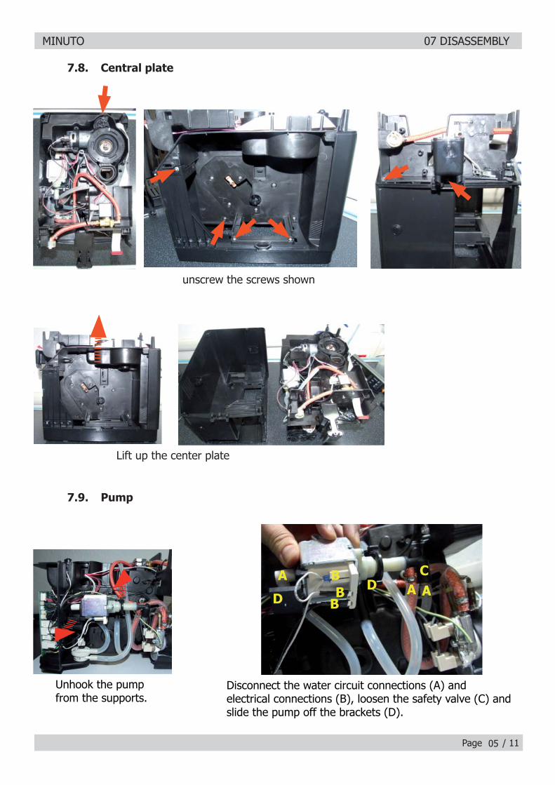
7.9. Pump
Disconnect the water circuit connections (A) and electrical connections (B), loosen the safety valve (C) and slide the pump off the brackets (D).
Unhook the pump from the supports.
C
DD A
AA
BB
B
7.8. Central plate
unscrew the screws shown
Lift up the center plate
MINUTO 07 DISASSEMBLY
Page / 11
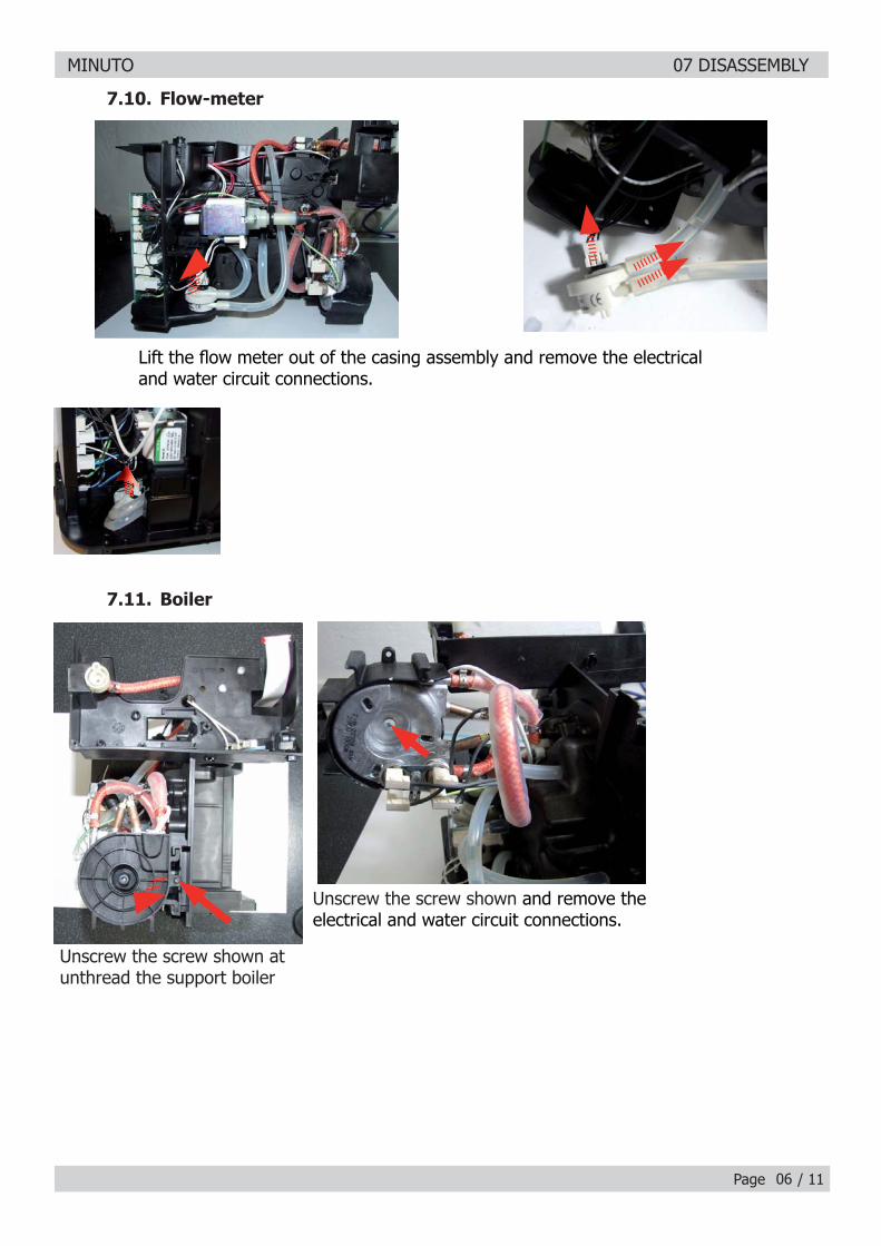
7.10. Flow-meter
Lift the fl ow meter out of the casing assembly and remove the electrical and water circuit connections.
Unscrew the screw shown and remove the electrical and water circuit connections.
06
Unscrew the screw shown at unthread the support boiler
7.11. Boiler
MINUTO 07 DISASSEMBLY
Page / 1107
7.14. KYB interface and display
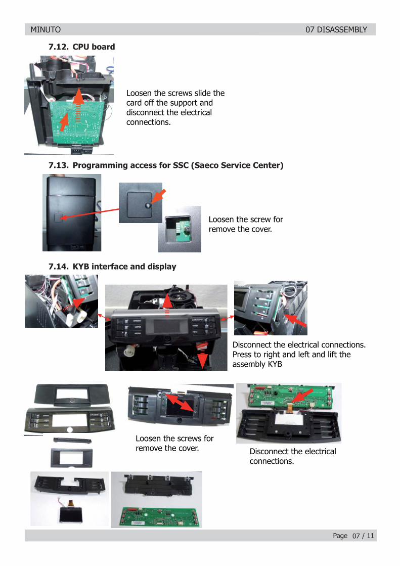
Disconnect the electrical connections.Press to right and left and lift the assembly KYB
Loosen the screws slide the card off the support and disconnect the electrical connections.
Loosen the screw for remove the cover.
7.12. CPU board
7.13. Programming access for SSC (Saeco Service Center)
Disconnect the electrical connections.
Loosen the screws for remove the cover.
MINUTO 07 DISASSEMBLY
Page / 11
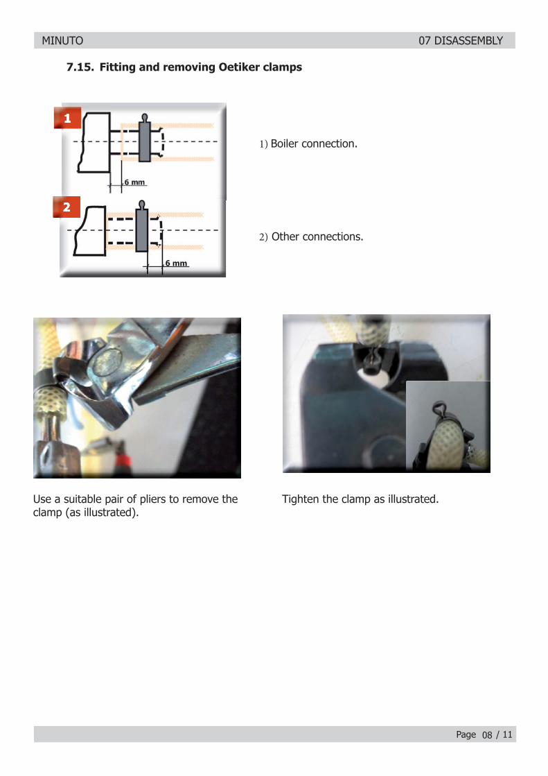
Use a suitable pair of pliers to remove the clamp (as illustrated).
Tighten the clamp as illustrated.
1) Boiler connection.
2) Other connections.
7.15. Fitting and removing Oetiker clamps
08

MINUTO
CHAPTER 8
NOTES

MINUTO 08 NOTES
Page / 0101
MINUTO
CHAPTER 9
WATER CIRCUIT DIAGRAM
MINUTO 09 WATER CIRCUIT DIAGRAM
Page / 0101
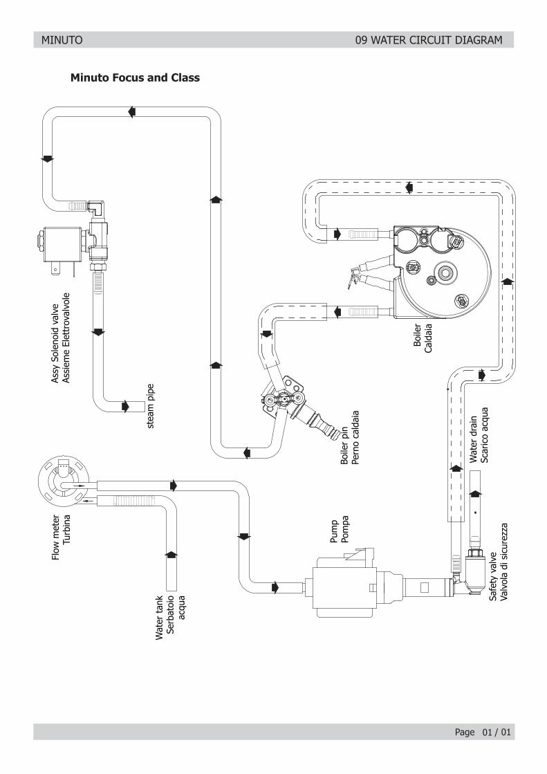
Flow
met
erTu
rbin
a
Wat
er t
ank
Serb
atoi
o ac
qua
Assy
Sol
enoi
d va
lve
Assi
eme
Elet
trov
alvo
le
stea
m p
ipe
Wat
er d
rain
Scar
ico
acqu
a
Pum
pPo
mpa
Boile
rCa
ldai
a
Safe
ty v
alve
Valv
ola
di s
icur
ezza
Boile
r pi
nPe
rno
cald
aia
Minuto Focus and Class
MINUTO
CHAPTER 10 ELECTRICAL DIAGRAM
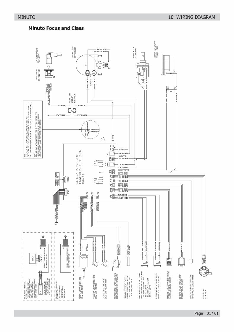
MINUTO 10 WIRING DIAGRAM
Page / 0101
Minuto Focus and Class