SERVICE MANUAL - Canon Globaldownloads.canon.com/color_imagerunner/Super_G3_Fax_Board_AB1_… ·...
52
SERVICE MANUAL Super G3 FAX Board-AB1 COPYRIGHT © 2010 CANON INC. CANON Super G3 Fax Board-AB1 REV. 1 PRINTED IN U.S.A. October 29, 2010 Rev. 1
-
Upload
trinhduong -
Category
Documents
-
view
215 -
download
0
Transcript of SERVICE MANUAL - Canon Globaldownloads.canon.com/color_imagerunner/Super_G3_Fax_Board_AB1_… ·...

SERVICEMANUAL
Super G3 FAX Board-AB1
COPYRIGHT © 2010 CANON INC. CANON Super G3 Fax Board-AB1 REV. 1 PRINTED IN U.S.A.
October 29, 2010
Rev. 1

ApplicationThis manual has been issued by Canon Inc. for qualified persons to learn technical theory, installation, maintenance, and repair
of products. This manual covers all localities where the products are sold. For this reason, there may be information in this
manual that does not apply to your locality.
CorrectionsThis manual may contain technical inaccuracies or typographical errors due to improvements or changes in products. When
changes occur in applicable products or in the contents of this manual, Canon will release technical information as the need
arises. In the event of major changes in the contents of this manual over a long or short period, Canon will issue a new edition
of this manual.
The following paragraph does not apply to any countries where such provisions are inconsistent with local law.
TrademarksThe product names and company names used in this manual are the registered trademarks of the individual companies.
CopyrightThis manual is copyrighted with all rights reserved. Under the copyright laws, this manual may not be copied, reproduced or
translated into another language, in whole or in part, without the written consent of Canon Inc.
COPYRIGHT © 2001 CANON INC.Printed in Japan
CautionUse of this manual should be strictly supervised to avoid disclosure of confidential information.
Introduction
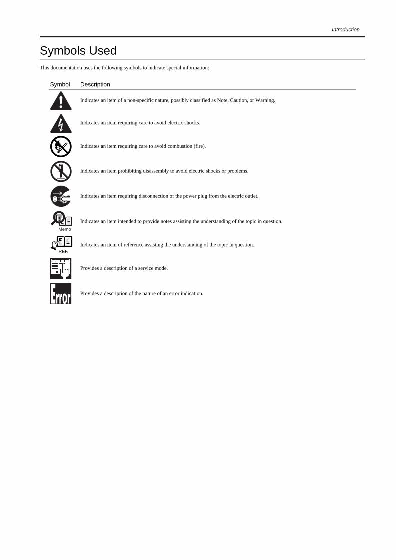
Symbols UsedThis documentation uses the following symbols to indicate special information:
Symbol Description
Indicates an item of a non-specific nature, possibly classified as Note, Caution, or Warning.
Indicates an item requiring care to avoid electric shocks.
Indicates an item requiring care to avoid combustion (fire).
Indicates an item prohibiting disassembly to avoid electric shocks or problems.
Indicates an item requiring disconnection of the power plug from the electric outlet.
Indicates an item intended to provide notes assisting the understanding of the topic in question.
Indicates an item of reference assisting the understanding of the topic in question.
Provides a description of a service mode.
Provides a description of the nature of an error indication.
Memo
REF.

Introduction
The following rules apply throughout this Service Manual:1. Each chapter contains sections explaining the purpose of specific functions and the relationship between electrical and mechanical systems with refer-
ence to the timing of operation.In the diagrams, represents the path of mechanical drive; where a signal name accompanies the symbol , the arrow indicates thedirection of the electric signal.The expression "turn on the power" means flipping on the power switch, closing the front door, and closing the delivery unit door, which results insupplying the machine with power.
2. In the digital circuits, '1'is used to indicate that the voltage level of a given signal is "High", while '0' is used to indicate "Low".(The voltage value, how-ever, differs from circuit to circuit.) In addition, the asterisk (*) as in "DRMD*" indicates that the DRMD signal goes on when '0'.In practically all cases, the internal mechanisms of a microprocessor cannot be checked in the field. Therefore, the operations of the microprocessorsused in the machines are not discussed: they are explained in terms of from sensors to the input of the DC controller PCB and from the output of theDC controller PCB to the loads.
The descriptions in this Service Manual are subject to change without notice for product improvement or other purposes, and major changes will be com-municated in the form of Service Information bulletins.All service persons are expected to have a good understanding of the contents of this Service Manual and all relevant Service Information bulletins and beable to identify and isolate faults in the machine."


Contents
Contents
Chapter 1 Specifications
1.1 Product Specifications ................................................................................................................................1- 11.1.1 FAX Specifications ..................................................................................................................................................1- 1
Chapter 2 Installation
2.1 Unpacking and Checking the Components ................................................................................................2- 12.1.1 Checking Contents ..................................................................................................................................................2- 1
2.2 Installation Procedure.................................................................................................................................2- 12.2.1 Turning OFF Power .................................................................................................................................................2- 12.2.2 Installation Procedure..............................................................................................................................................2- 12.2.3 After Installation.......................................................................................................................................................2- 5
2.3 Attaching the Labels etc. ............................................................................................................................2- 52.3.1 Putting Labels..........................................................................................................................................................2- 5
2.4 Checking the Operation..............................................................................................................................2- 52.4.1 Type Settings...........................................................................................................................................................2- 52.4.2 Line Type Setting.....................................................................................................................................................2- 52.4.3 FAX Communication Test........................................................................................................................................2- 5
Chapter 3 Functions
3.1 Basic Construction......................................................................................................................................3- 13.1.1 Overview..................................................................................................................................................................3- 1
Chapter 4 Parts Replacement Procedure
4.1 Removing from the Host Machine ..............................................................................................................4- 14.1.1 FAX Unit ..................................................................................................................................................................4- 1
4.1.1.1 Pre-operation ........................................................................................................................................................................... 4- 14.1.1.2 Removing the NCU PCB.......................................................................................................................................................... 4- 34.1.1.3 Removing the Off Hook PCB ................................................................................................................................................... 4- 3
Chapter 5 Service Mode
5.1 Outline ........................................................................................................................................................5- 15.1.1 Service Mode Configuration ....................................................................................................................................5- 15.1.2 Exiting Service Mode...............................................................................................................................................5- 35.1.3 Service Mode Backup..............................................................................................................................................5- 35.1.4 Service Mode Backup..............................................................................................................................................5- 4
5.2 Setting of Bit Switch (SSSW)......................................................................................................................5- 65.2.1 Outline .....................................................................................................................................................................5- 6
5.2.1.1 SSSW List................................................................................................................................................................................ 5- 65.3 Setting of Menu Switch (MENU).................................................................................................................5- 7
5.3.1 MENU List ...............................................................................................................................................................5- 75.4 Setting of Numeric Parameter (NUMERIC Param.)....................................................................................5- 7
5.4.1 NUM List..................................................................................................................................................................5- 7

Contents

Chapter 1 Specifications


Contents
Contents
1.1 Product Specifications....................................................................................................................................................1-11.1.1 FAX Specifications ...................................................................................................................................................................... 1-1


Chapter 1
1-1
1.1 Product Specifications
1.1.1 FAX Specifications0021-1613
T-1-1
Model Super G3 Fax Board-AB1
Applicable lines Public Switched Telephone Network (PSTN)* PSTN currently supports the modem speed of up to 28.8Kbps. It, however, differs depending on the telephone line condition.
Number of lines connected: 1Transmission method G3
Modulation method Image modulation: V.34/V.17/V.29/V.27terTransmission procedure: V.21
Transmission speed Transmission speed:Approx. 3 sec per page ECM-JBIG, Transmitted from memory at 33.6Kbps* Based on the JBIG standard mode with ITU-T standard chart No. 1
Modem speed:33,600bps, Automatic fallback
Coding Compression method: JBIG, MMR, MR, MH
Error correction ECM
Scanning line density Reading: 8x 3.85/7.7/15.4 16x15.4Recording: 600 x 600dpi
Scanning density adjustment 9 levels, manual adjustment
Half tone 256 gradation
Printing resolution Resolution conversion: Provided
<200 x 100dpi>: 8 pixels/mm x 3.85 lines/mm<200 x 200dpi>: 8 pixels/mm x 7.7 lines/mm<200 x 400dpi>: 8 pixels/mm x 15.4 lines/mm<400 x 400dpi>: 16 pixels/mm x 15.4 lines/mm
Reduction for reception Automatic reduction of an image received: 75 to 100% (incremented by 1%)
FAX/TEL switching Provided
Remote reception Provided
Memory reception Send/Receive memory: More than 1000 pages (Total number of sent/received pages)*Based on the JBIG standard mode with ITU-T standard chart No. 1
Memory reception: ProvidedOthers Dialing method
- Address book (300 destinations)Group dialing (299 destinations)(incl. One-touch button (200 destinations))- Regular dialing (by numeric keys)- Automatic redialing, manual redialing (specified from the calling record)- Broadcast transmission (301 destinations)
Output of reports- Communication management report (Automatically printed for every 40 calls)- Transmission result report / Reception result report
Reception method- Automatic reception- Remote reception by a telephone set (Initial setting ID: 25)
Redial Automatic redialing: Provided
Memory backup Number of memories which can be accumulated: 1236 sheetsMemory backup time: 1 hour
Time Within 60 sec per month (Zone A)Within 90 sec per month (Zone B)


Chapter 2 Installation


Contents
Contents
2.1 Unpacking and Checking the Components ....................................................................................................................2-12.1.1 Checking Contents ....................................................................................................................................................................... 2-1
2.2 Installation Procedure ....................................................................................................................................................2-12.2.1 Turning OFF Power ..................................................................................................................................................................... 2-12.2.2 Installation Procedure .................................................................................................................................................................. 2-12.2.3 After Installation .......................................................................................................................................................................... 2-5
2.3 Attaching the Labels etc.................................................................................................................................................2-52.3.1 Putting Labels .............................................................................................................................................................................. 2-5
2.4 Checking the Operation .................................................................................................................................................2-52.4.1 Type Settings ............................................................................................................................................................................... 2-52.4.2 Line Type Setting......................................................................................................................................................................... 2-52.4.3 FAX Communication Test ........................................................................................................................................................... 2-5


Chapter 2
2-1
2.1 Unpacking and Checking the Components
2.1.1 Checking Contents0020-1952
F-2-1
2.2 Installation Procedure
2.2.1 Turning OFF Power0020-1325
1) Turn OFF the main power switch.2) Remove the power plug (for outlet).
2.2.2 Installation Procedure0020-1805
1) Remove the reader hinge cover [1].- 4 claws [2]
F-2-22) Remove the rear cover unit [1].
- 2 screws [2]- 9 claws [3]
[2] [3]
[8] [9] [10]
[1] NCU board 1pc [2] OFF HOOK unit 1pc
[3] Flat cable 1pc [4] NCU cable 1pc
[5] NCU-modular cable 1pc [6] NCU-OFF-HOOK cable 1pc
[7] OFF HOOK cable 1pc [8] Edge saddle 2pc
[9] Wire saddle 2pc [10] Screw (TP; M3X6) 5pc
[11]* Telephone cord 1pc [12] Approval label(For USA/AUS/EUR product only)
1pc
* Connector shape differs depending on destinations
4 pieces are included in the EUR products.
3 pieces are included in the KOR products.
NOTE:Since the host machine is not equipped with the hard disk, shut-down sequence is not required to turn OFF the main power switch.
[2]
[2]
[1]

Chapter 2
2-2
F-2-33) Remove the 3 screws[1].
F-2-44) Move the left cover [2] to the position where the 2 screws [1] of the power
unit cover can be removed.
F-2-55) Remove the power unit cover [1].
- 12 screws [2]- 1 terminal [3]
CAUTION:When the cassette pedestal is installed, rotate the cassette pedestal fixing member [1] in the direction of the arrow and remove the cassette pedestal connecting member [2].
[3]
[2]
[3]
[3]
[3]
[1]
[1]
[2]
[1]
[2][1]
[2]
[1][1]

Chapter 2
2-3
F-2-66) Connect the flat cable connector [1] and the NCU cable connector [2].
F-2-77) Install the NCU board [1].
- 2 hooks [2]- 2 screws (TP; M3X6) [3]
F-2-88) Connect the flat cable connector [1] and the NCU cable connector [2].
F-2-99) Install the edge saddle [1] and the 2 wire saddles [2].
F-2-1010) Connect the 2 NCU-modular cable connectors [1] and path them through
the edge saddle [2].
[3][1]
[2]
[2]
[1][2]
[1]
[2]
[3]
[1]
[2]
[1] [2]

Chapter 2
2-4
F-2-1111) Install the edge saddle [1].
F-2-1212) HOOK the claw [1] of the OFF HOOK unit onto the plate hole [2].
Insert the OFF HOOK unit [3] in the direction of the arrow and engage the hook [4] with the cut-off [5].
F-2-1313) Fix the OFF HOOK unit [1].
- 3 screws (TP; M3X6) [2]
F-2-1414) Put the NCU-OFF HOOK cable through the edge saddle [1] and connect
the 2 NCU-OFF HOOK cable connectors [2].15) Secure the cable with 2 wire saddles [3] and put it through the harness
guide [4].
F-2-15
[1]
[1]
[2]
[1]
[3]
[4]
[1]
[2]
[5]
[1]
[2]
[2]
[1] [4] [2][2] [3]

Chapter 2
2-5
16) Connect the 2 OFF HOOK cable connectors [1] and secure them with the2 edge saddles [2].
F-2-1617) Install the removed parts.
- Power unit cover- Left cover- Rear cover unit- Reader hinge cover
18) Remove the blanking sheet [1].
F-2-17
2.2.3 After Installation0020-1327
1) Connect the telephone cord to the modular jack on the wall and connectthe other side to the modular jack (for lines) of the host machine.
2) If using an extensional phone, connect the modular jack of extensionalphone to the modular jack ' ' of this equipment.
3) Connect the power plug of the host machine into outlet and turn ON themain power switch.
2.3 Attaching the Labels etc.
2.3.1 Putting Labels0020-1723
1) Put the approval label [1] on the indicated position as below.
F-2-18
2.4 Checking the Operation
2.4.1 Type Settings0020-1796
Specify the parameter corresponding to the communication standard of eachcountry/area.1) Specify the country/area settings of the FAX board in service mode.Enter the service mode (Main Menu > 2 > 8 > Main Menu)
COPIER > FUNCTION > CLEAR > TYPE
2) Exit the service mode.3) If changing the setting in step 1), turn OFF/ON the main power switch.
2.4.2 Line Type Setting0020-2619
Specify the setting of connected phone line.1) Select the line types (manual) in additional function mode.
[Additional Func.] > [Communications Settings] > [FAX Settings] >[User Settings] > [Tel. Line Type Selection] > [Manual]
2) Specify the phone line to either dial Pulse (20PPS/10PPS) or Tone.
2.4.3 FAX Communication Test0020-1743
Perform a communication test to check whether the FAX function workscorrectly.1) Shift the control panel to the [Send/FAX] screen.2) Send the test data from the host machine to other party that can accept the
transmission test to check that the machine can send a data correctly.3) Send the test data from other party to the host machine to check that the
machine can receive a data correctly.
[1]
[2]
[1]
NOTE:When this operation is made, it takes approx 1 min for parameter setting.Key operations are disabled during the time.
[1]


Chapter 3 Functions


Contents
Contents
3.1 Basic Construction .........................................................................................................................................................3-13.1.1 Overview...................................................................................................................................................................................... 3-1


Chapter 3
3-1
3.1 Basic Construction
3.1.1 Overview0021-0516
The board is designed to enable a digital copier to serve as a high-performance multi-functional machine (image processing functions and communication functionsover the telephone line).It is capable of communicating at a maximum rate of 33.6 kbps, thanks to the presence of a V.34-compliant modem (ITU-T).
F-3-1[1] Main controller PCB[2] NCU PCB[3] Off hook PCB
[1] [2]
[3]


Chapter 4 Parts Replacement Procedure


Contents
Contents
4.1 Removing from the Host Machine.................................................................................................................................4-14.1.1 FAX Unit ..................................................................................................................................................................................... 4-1
4.1.1.1 Pre-operation ...................................................................................................................................................................................................4-14.1.1.2 Removing the NCU PCB ................................................................................................................................................................................4-34.1.1.3 Removing the Off Hook PCB .........................................................................................................................................................................4-3


Chapter 4
4-1
4.1 Removing from the Host Machine
4.1.1 FAX Unit
4.1.1.1 Pre-operation0021-1624
1) Open the front cover [1].
F-4-12) While pushing the ETB lock lever [1] (2 points at left and right), remove
the ETB unit [2].
F-4-2
3) Remove the reader hinge cover [1].- 4 claws [2]
F-4-34) Remove the rear cover unit [1].
- 2 screws [2]- 9 claws [3]
Points to Note At HandlingBe careful not to touch the surface of the ETB belt or damage it.Dirts or small cuts on the belt may cause image faults.
[1]
[1]
[1]
[2]
When closing the front cover with the ETB unit removed and then and opening it, the drawer connector [1] faces upward. The drawer connector facing upward may cause the following symptoms; and therefore, be sure to put down the 2 drawer connectors [1] if necessary.
- When the toner cartridge is not removedThe shutter of the toner cartridge is opened, resulting in deteriorated sensitivity of the photosensitive drum.- When the toner cartridge is removedThe coupling [2] and lock mechanism [3] of the toner cartridge works together and the toner cartridge cannot be installed.
[1]
[1]
[2]
[3]
[2]
[2]
[1]
Chapter 4
4-2
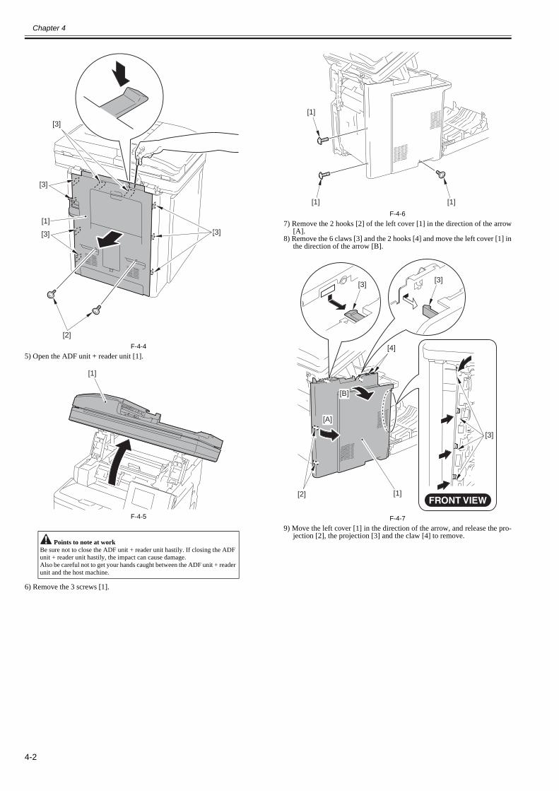
F-4-45) Open the ADF unit + reader unit [1].
F-4-5
6) Remove the 3 screws [1].
F-4-67) Remove the 2 hooks [2] of the left cover [1] in the direction of the arrow
[A].8) Remove the 6 claws [3] and the 2 hooks [4] and move the left cover [1] in
the direction of the arrow [B].
F-4-79) Move the left cover [1] in the direction of the arrow, and release the pro-
jection [2], the projection [3] and the claw [4] to remove. Points to note at work
Be sure not to close the ADF unit + reader unit hastily. If closing the ADF unit + reader unit hastily, the impact can cause damage.Also be careful not to get your hands caught between the ADF unit + reader unit and the host machine.
[3]
[2]
[3]
[3]
[3]
[1]
[1]
[1]
[1]
[1]
[4]
[2] [1]
[A]
[B]
[3][3]
[3]

Chapter 4
4-3
F-4-8
10) Remove the electrical components cover [1].- 12 screws [2]- 1 terminal [3]
F-4-9
4.1.1.2 Removing the NCU PCB0021-1629
1) Remove the NCU PCB.- 1 flat cable [2]- 3 connectors [3]- 2 screws [4]
F-4-10
4.1.1.3 Removing the Off Hook PCB0021-1631
1) Remove the the Off Hook PCB unit [1].
Point to Note at InstallationBe sure to install the left cover by fitting the boss [1] and the projection [2] of the left cover with the harness guide hole [3] and the groove [4] of the host machine.
[2]
[1]
[3]
[4]
[3] [4]
[1]
[2]
[1]
[2]
[3]
[2]
[2]
[1]
[2]
[3]
[3]
[4]
[4]

Chapter 4
4-4
- 2 connectors [2]- 3 screws [3]- 1 hook [4]
F-4-11
[2][1]
[4]
[3]
[3][2]

Chapter 5 Service Mode


Contents
Contents
5.1 Outline............................................................................................................................................................................5-15.1.1 Service Mode Configuration........................................................................................................................................................ 5-15.1.2 Exiting Service Mode .................................................................................................................................................................. 5-35.1.3 Service Mode Backup .................................................................................................................................................................. 5-35.1.4 Service Mode Backup .................................................................................................................................................................. 5-4
5.2 Setting of Bit Switch (SSSW)........................................................................................................................................5-65.2.1 Outline.......................................................................................................................................................................................... 5-6
5.2.1.1 SSSW List .......................................................................................................................................................................................................5-65.3 Setting of Menu Switch (MENU) ..................................................................................................................................5-7
5.3.1 MENU List................................................................................................................................................................................... 5-75.4 Setting of Numeric Parameter (NUMERIC Param.) .....................................................................................................5-7
5.4.1 NUM List ..................................................................................................................................................................................... 5-7


Chapter 5
5-1
5.1 Outline
5.1.1 Service Mode Configuration0021-1636
The service mode screen transition is shown below.
F-5-1
1) Main menu key2) 2 key3) 8 key4) Main menu key
Back key
Back key
Back key
OK key or Back key
User screen
Initial screen
Main item screen
Intermediateitem screen
Sub item screen
Main item screen
Intermediateitem screen
Sub item screen
Settings screen
Back key

Chapter 5
5-2
The machine's service mode is categorized in to the following modes.
F-5-2
COPIER
FEEDER
ADJUST
FUNCTION
Adjustment mode
Service mode for ADF
Operation/Checking mode
FAX
DISPLAY
I/O
ADJUST
FUNCTION
OPTION
COUNTER
Status display mode
Service mode for a copier machine
I/O display mode
Adjustment mode
Operation/Checking mode
Machine settings mode
Counter mode
SSSW
MENU
NUM
NCU
Bit switch registration mode
Service mode for FAX (Displayed only when FAX is installed)
TESTMODE Service mode used to perform test print or operation check
Menu switch registration mode
Numeric value parameter settings mode
NCU parameter settings mode
Service mode
SYSTEM
SCAN
FAX
PANEL
System test mode
Scan test mode
Print test mode
FAX test mode
Control panel test mode

Chapter 5
5-3
5.1.2 Exiting Service Mode0021-1639
Every time the Return key is pressed in a screen other than the initial screen, the screen goes back to the previous one.When the Return key is pressed in the initial screen, the screen goes back to the main menu screen.
5.1.3 Service Mode Backup0021-1641
Since there is no service label in the machine, printing in the service mode setting value is not available either.Hence, adjustment in the market is being performed. Please note that when the value service mode is modified, be sure to record the modified value.
When using the service mode (ADJUST, FUNCTION, OPTION), be sure to turn the main power switch OFF/ON after exiting the service mode.
MEMO:When PCB is replaced or RAM clearing is performed, the adjusted ADJUST and OPTION value will return to default value.

Chapter 5
5-4
5.1.4 Service Mode Backup0021-1642
Initial/Main/Intermediate screenTo select the item: / key or scroll wheelTo display the items on the lower layer: OK keyTo display the items on the upper layer: Back key
Sub screen 1To select the item: / key or scroll wheelTo display the each setting screen: OK keyTo display the intermediate screen: Back keySetting value: [1]Setting range: [2]
ON/OFF selection screenTo select the setting: / key or scroll wheelTo change the setting: OK keyNot change the setting: Back key
Numeric value entry screen 1To enter the setting value: Numeric keysTo increase the setting value by 1: key or scroll wheel (clockwise)To decrease the setting value by 1: key or scroll wheel (counterclockwise)To enter the negative setting value: Right any key (if displayed), key or scroll wheel
(counterclockwise) (continue to operate until the value smaller than 0 is displayed)
To change the setting: OK keyNot change the setting: Back key
Switch selection screenTo select the switch: / key or scroll wheelTo display the entry screen of switch setting value: OK keyTo display the small screen: Back key
C O P I E R
F E E D E R
F A X
T E S T M O D E
[2][1]
0

Chapter 5
5-5
Entry screen of switch setting valueTo select the setting item: / keyTo switch the setting value: Right any key (0 or 1 can be selected)To change the setting: OK keyNot change the setting: Back key
Small screen 2To select the item: / key or scroll wheelTo display the each setting screen: OK keyTo display the previous screen: Back keySetting value: [1]
Item selection screenTo select the setting: / key or scroll wheelTo change the setting: OK keyNot change the setting: Back key
Numeric value entry screen 2To enter the setting value: Numeric keysTo change the setting: OK keyNot change the setting: Back key
[1]
Chapter 5
5-6
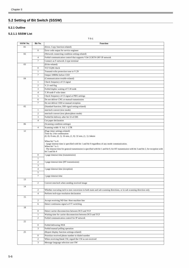
5.2 Setting of Bit Switch (SSSW)
5.2.1 Outline
5.2.1.1 SSSW List0021-1880
T-5-1
SSSW No. Bit No. Function01 (Error, Copy function-related)
0 Error code output for service engineer02 (Network connecting condition setting-related)
4 Forbid communication control that supports V34 CCRTN OFF IP network7 Connect as F-network 2-type terminal
03 (Echo-related)0 TCF EQM check1 Transmit echo protection tone to V.297 Output 1080Hz before CED
04 (Communication trouble-related)1 Check frequency of CI signal2 V.21 end flag3 Forbid duplex waiting of T.30 node4 T.30 node F echo timer5 Check frequency of CI signal at PBX settings6 Do not deliver CNG at manual transmission7 Do not deliver CED at manual reception
05 (Standard function, DIS signal setting-related)1 mm/inch convert (text mode)2 mm/inch convert (text photo/photo mode)3 Forbid bit delivery after bit 33 of DIS4 Cut paper declaration
06 (Scanning condition settings)4 Scanning width 0: A4, 1: LTR
12 (Page timer settings-related) Time by 2-bit combination(0, 0): 8 min, (0, 1): 16 min, (1, 0): 32 min, (1, 1): 64min
When bit 7 is 0:- 1page timeout time is specified with bit 1 and bit 0 regardless of any mode communication.When bit 7 is 1:- The timeout time for general transmission is specified with bit 1 and bit 0, for HT transmission with bit 3 and bit 2, for reception with bit 5 and bit 4
0 1 page timeout time (transmission)12 1 page timeout time (HT transmission)34 1 page timeout time (reception)57 1 page timeout time
132 Convert mm/inch when sending received image
142 Whether executing inch to mm conversion in both main and sub scanning directions, or in sub scanning direction only4 Perform inch-type resolution declaration
152 Accept receiving ND line: Host machine line6 Detect continuous signal at F/T switching
180 Detect carrier disconnection between DCS and TCF1 Waiting time for carrier disconnection between DCS and TCF2 Forbid communication control for IP network
220 Forbid delivering NSX3 Forbid manual polling operation
25 (Report display function settings-related)0 Prioritize received phone number to dialed number2 When receiving blank CSI, regard the CSI as not-received3 Message language selection user SW

Chapter 5
5-7
5.3 Setting of Menu Switch (MENU)
5.3.1 MENU List0021-1873
T-5-2
5.4 Setting of Numeric Parameter (NUMERIC Param.)
5.4.1 NUM List0021-1874
T-5-3
280 Forbid V8 procedure at calling side1 Forbid V8 procedure at receiving side2 Forbid V8 late start at calling side3 Forbid V8 late start at receiving side4 Forbid fallback start from V.34 receiving side5 Forbid fallback start from V.34 sending side
305 New dial tone detection method
325 0: NCU2004, 1: NCU2002
330 (Record) whether to count B4 size as large size or not2 (Scan) whether to count B4 size as large size or not5 Display toner replacement counter
350 e-RDS function (0: OFF/1: ON)
Registration mode of menu switchNumber Parameter Description of the selection
05 ON/OFF of NL equalizer 0: OFF, 1: ON06 Telephone line monitor 0: DIAL, 1: SERVICEMAN1, 2: SERVICEMAN2, 3: OFF07 Delivery level (ATT) 0-1508 Upper limit of V.34 modulating speed 0: 3429BAUD, 1: 3200BAUD, 2: 3000BAUD,
3: 2800BAUD, 4: 2743BAUD, 5: 2400BAUD09 Upper limit of V. 34 data speed (Unit: kbps)
0: 33.6, 1: 31.2, 2: 28.8, 3: 26.4, 4: 24.0, 5: 21.6, 6: 19.2, 7: 16.8, 8: 14.4, 9: 12.0, 10: 9.6, 11: 7.2, 12: 4.8, 13: 2.4
10 Frequency of pseudo CI signal 0: 50 Hz, 1: 25 Hz, 2: 17 Hz
Numeric parameter setting modeNumber Parameter Available setting range
02 RTN delivery condition X 1 to 99%03 RTN delivery condition n 2 to 99 times04 RTN delivery condition m 1 to 99 lines05 NCC pause time (before ID code) 1 to 60 s06 NCC pause time (after ID code) 1 to 60 s10 T.30 T0 timer Generally 55s11 T.30 T1 timer (for receiving) 0 to 9999 (France = 3500, Others = 3000)12 Maximum number of receiving lines 0 to 65535 (lines) Unlimited for 013 T.30 EOL timer 500 to 3000 (Default: 55s)15 Threshold for hooking and on-hook 0 to 99916 Time to temporarily response at FAX/TEL switching 0 to 917 Pseudo RBT cadence ON time 0 to 99918 Pseudo RBT cadence OFF time (short) 0 to 99919 Pseudo RBT cadence OFF time (long) 0 to 99920 Pseudo ring tone cadence ON time 0 to 99921 Pseudo CI cadence OFF time (short) 0 to 99922 Pseudo CI cadence OFF time (long) 0 to 99923 CNG detection level at FAX/TEL switching 0 to 724 Pseudo RBT delivery level at FAX/TEL switching 10 to 20 (100V),
0 to 20 (120/ 230V)25 CNG monitoring time when answer phone is used 0 to 99926 Level to detect no-sound when answer phone is used 0 to 727 Preamble detection time of V21 low-speed flag 20 (* 10ms)51 Threshold value of hook detection 10 to
SSSW No. Bit No. Function

Chapter 5
5-8
53 Set the number of DTMF ringing times at FAX remote reception 10 to (Default: 25)54 Set the transmission time of BusyTone when the handset is used55 Cycle to obtain data of environment log 0 to 480 min (Default: 60min) (No data is obtained with 0)56 Select counter type to be displayed at counter 1 10157 Select counter type to be displayed at counter 2 0 to 99958 Select counter type to be displayed at counter 3 0 to 99959 Select counter type to be displayed at counter 4 0 to 99960 Select counter type to be displayed at counter 5 0 to 99961 Select counter type to be displayed at counter 6 0 to 99974 Port number of e-RDS RGW75 Transmission interval of e-RDS for 3rd party
Numeric parameter setting modeNumber Parameter Available setting range

Oct 29 2010