
Sequential System Synthesis -- Introduction. ENEE 6442 Outline > Combinational Circuits vs....
22
Sequential System Synthesis Sequential System Synthesis -- Introduction -- Introduction
-
date post
21-Dec-2015 -
Category
Documents
-
view
216 -
download
1
Transcript of Sequential System Synthesis -- Introduction. ENEE 6442 Outline > Combinational Circuits vs....

Sequential System SynthesisSequential System Synthesis-- Introduction-- Introduction
ENEE 644 2
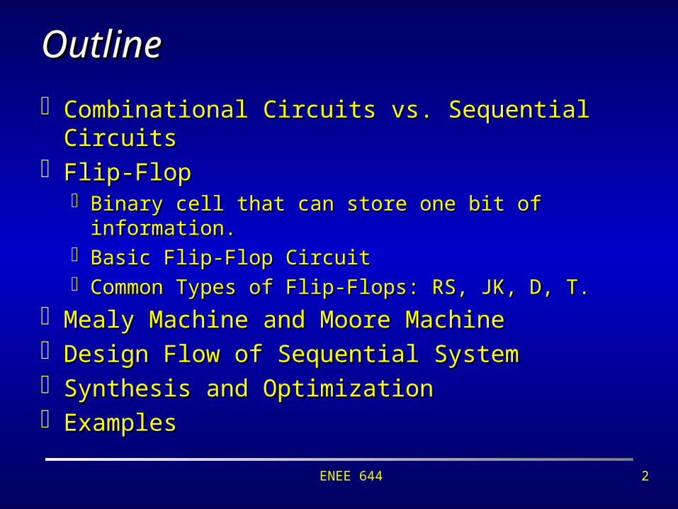
OutlineOutline
Combinational Circuits vs. Sequential CircuitsCombinational Circuits vs. Sequential Circuits Flip-FlopFlip-Flop
Binary cell that can store one bit of information.Binary cell that can store one bit of information. Basic Flip-Flop CircuitBasic Flip-Flop Circuit Common Types of Flip-Flops: RS, JK, D, T.Common Types of Flip-Flops: RS, JK, D, T.
Mealy Machine and Moore MachineMealy Machine and Moore Machine Design Flow of Sequential SystemDesign Flow of Sequential System Synthesis and Optimization Synthesis and Optimization ExamplesExamples

ENEE 644 3
Combinational CircuitsCombinational Circuits
A circuit is A circuit is combinationalcombinational if it computes a function if it computes a function which depends only on the current inputs applied which depends only on the current inputs applied to the circuit; to the circuit; for every input set of values, there is a unique output set of values. Acyclic circuits are necessarily combinationalAcyclic circuits are necessarily combinational Cyclic circuits can be combinational Cyclic circuits can be combinational
• in fact, there are combinational circuits whose in fact, there are combinational circuits whose minimal implementation must have cycles [Kautz minimal implementation must have cycles [Kautz 1970]1970]

ENEE 644 4
Sequential CircuitsSequential Circuits
In a In a sequential sequential circuit, the output values may be circuit, the output values may be different for the same set of input values; the different for the same set of input values; the output depends on the current contents of output depends on the current contents of memory elements as well.memory elements as well. Feedback (cyclic) is a necessary condition for a circuit Feedback (cyclic) is a necessary condition for a circuit
to be sequential.to be sequential. Synthesis of sequential circuits is not as well Synthesis of sequential circuits is not as well
developed as combinational. (only small circuits)developed as combinational. (only small circuits) Sequential synthesis techniques are not really used in Sequential synthesis techniques are not really used in
commercial software (except maybe retiming). commercial software (except maybe retiming).

ENEE 644 5
CombinationalCombinational
SequentialSequential
Combinational Logic Circuit
x0x1
xn
z0z1
zm
Combinational Logic Circuit
Memory Elements
inputsoutputs
Logic CircuitsLogic Circuits
Sequential Logic Circuit

ENEE 644 6
Two Output (Q and Q’)Two Output (Q and Q’) Various Ways to Feed Flip-FlopsVarious Ways to Feed Flip-Flops NOR Gate Flip-FlopsNOR Gate Flip-Flops
Basic Flip-FlopBasic Flip-Flop
QR
Q’S
1
2
S R Q Q’
1 0 1 0
0 0 1 0
0 1 0 1
0 0 0 1
S R Q Q’
1 0 0 1
1 1 0 1
0 1 1 0
1 1 1 0
QS
Q’R
1
2
NAND Gate Flip-FlopsNAND Gate Flip-Flops

ENEE 644 7
RS Flip-FlopRS Flip-Flop
Three Inputs: Three Inputs: Clock Pulse: additional input to control when state is changing.Clock Pulse: additional input to control when state is changing. S(et) inputS(et) input R(eset) inputR(eset) input
Four States:Four States: Set state: Set state: S=1, R=0, CP=1S=1, R=0, CP=1 (Q=1, Q’=0)(Q=1, Q’=0) Reset state: Reset state: S=0, R=1, CP=1S=0, R=1, CP=1 (Q=0, Q’=1)(Q=0, Q’=1) Indetermined:Indetermined: S=1, R=1, CP=1S=1, R=1, CP=1 (Q=1, Q’=1)(Q=1, Q’=1) No change:No change: S=0, R=0, CP=1S=0, R=0, CP=1
S
R
Q
Q’
1
2
3
4
CPS>R
QQ’

ENEE 644 8
RS Flip-Flop (cont’d)RS Flip-Flop (cont’d)
Characteristic Equation:Characteristic Equation:Q(t+1) = F(Q(t), S(t+1), R(t+1))Q(t+1) = F(Q(t), S(t+1), R(t+1))
= = S + R’Q
SR = 0
Characteristic Table:Characteristic Table:
SS RR QQ Q(t+1)Q(t+1)
00 00 00 00
00 00 11 11
00 11 00 00
00 11 11 00
11 00 00 11
11 00 11 11
11 11 00 i.d.i.d.
11 11 11 i.d.i.d.

ENEE 644 9
JK Flip-FlopJK Flip-Flop
Three Inputs: Three Inputs: CP: Clock PulseCP: Clock Pulse J: Set inputJ: Set input K:Reset inputK:Reset input
J>
K
Q
Q’
K
J
Q
Q’
CP
1
2
3
4
Four States:Four States: Set state: Set state: J=1, K=0, CP=1J=1, K=0, CP=1 Reset state: Reset state: J=0, K=1, CP=1J=0, K=1, CP=1 No change:No change: J=0, K=0, CP=1 J=0, K=0, CP=1 Complement:Complement:J=1, K=1, CP=1J=1, K=1, CP=1
ENEE 644 10
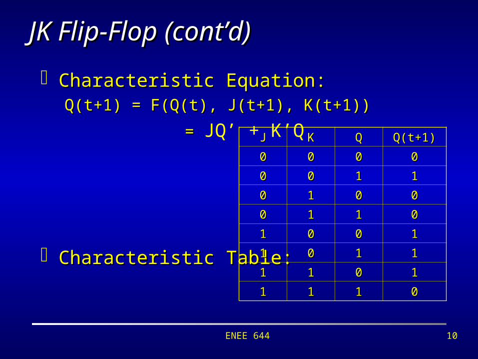
JK Flip-Flop (cont’d)JK Flip-Flop (cont’d)
Characteristic Equation:Characteristic Equation:Q(t+1) = F(Q(t), J(t+1), K(t+1))Q(t+1) = F(Q(t), J(t+1), K(t+1))
= = JQ’ + K’Q
Characteristic Table:Characteristic Table:
JJ KK QQ Q(t+1)Q(t+1)
00 00 00 00
00 00 11 11
00 11 00 00
00 11 11 00
11 00 00 11
11 00 11 11
11 11 00 11
11 11 11 00

ENEE 644 11
D Flip-FlopD Flip-Flop
Two Inputs: Two Inputs: CP: Clock PulseCP: Clock Pulse D: Set inputD: Set input
D’: Reset inputD’: Reset input
DQ
Q’
CP D> Q
Q’
1
2
3
4
Two States:Two States: Set state: Set state: D=1, CP=1D=1, CP=1 Reset state: Reset state: D=0, CP=1D=0, CP=1
Characteristic Equation:Characteristic Equation:Q(t+1) = F(Q(t), D(t+1)) = DQ(t+1) = F(Q(t), D(t+1)) = D

ENEE 644 12
T Flip-FlopT Flip-Flop
One input JK flip-flopOne input JK flip-flop Two States:Two States:
No Change:No Change: T=0, CP=1T=0, CP=1 Complement:Complement:T=1, CP=1T=1, CP=1
Characteristic Equation:Characteristic Equation: Q(t+1) = F(Q(t), T(t+1)) = TQ’+T’QQ(t+1) = F(Q(t), T(t+1)) = TQ’+T’Q
T Q
Q’
CPT> Q
Q’
1
2
3
4

ENEE 644 13
Excitation table: Excitation table: the reverse of characteristic table, the reverse of characteristic table, indicates how we should change flip-flop inputs to indicates how we should change flip-flop inputs to make the required state transition.make the required state transition.
SS RR QQ Q(t+1)Q(t+1)
00 00 00 00
00 00 11 11
00 11 00 00
00 11 11 00
11 00 00 11
11 00 11 11
11 11 00 i.d.i.d.
11 11 11 i.d.i.d.characteristic table
Q(t)Q(t) Q(t+1)Q(t+1) SS RR
00 00 00 xx
00 11 11 00
11 00 00 11
11 11 xx 00
excitation table
Excitation TableExcitation Table

ENEE 644 14
Q(t)Q(t) Q(t+1)Q(t+1) SS RR
00 00 00 xx
00 11 11 00
11 00 00 11
11 11 xx 00
Q(t)Q(t) Q(t+1)Q(t+1) JJ KK
00 00 00 xx
00 11 11 xx
11 00 xx 11
11 11 xx 00
Q(t)Q(t) Q(t+1)Q(t+1) DD
00 00 00
00 11 11
11 00 00
11 11 11
Q(t)Q(t) Q(t+1)Q(t+1) TT
00 00 00
00 11 11
11 00 11
11 11 00
Flip-Flop Excitation TablesFlip-Flop Excitation Tables

ENEE 644 15
State, State Reduction and AssignmentState, State Reduction and Assignment
A A statestate of a sequential circuit is defined by the binary of a sequential circuit is defined by the binary information stored in the memory elements (e.g. flip-flop).information stored in the memory elements (e.g. flip-flop). One flip-flop stores one bit, so m flip-flops can define at most 2One flip-flop stores one bit, so m flip-flops can define at most 2mm
states.states. Two states are Two states are equivalentequivalent if for any input, they produce the same if for any input, they produce the same
outputs and move to the same or equivalent states.outputs and move to the same or equivalent states.
State Reduction problemState Reduction problem: reduce the number of flip-flops : reduce the number of flip-flops in a sequential circuit.in a sequential circuit.
State Assignment problemState Assignment problem: assign binary values to states : assign binary values to states such that the cost of the flip-flop input functions is such that the cost of the flip-flop input functions is reduced.reduced.

ENEE 644 16
Mealy and Moore ModelsMealy and Moore Models A sequential system is of A sequential system is of Mealy typeMealy type if output if output
values depend on both present states and values depend on both present states and inputs.inputs. Recall that a state is a combination of the memory Recall that a state is a combination of the memory
element’s content.element’s content.
A sequential system is of A sequential system is of Moore typeMoore type if output if output values depend only on the present states. values depend only on the present states. This does not mean that output is independent of the This does not mean that output is independent of the
inputs. Instead, the impact is through memory units.inputs. Instead, the impact is through memory units.

ENEE 644 17
Sequential Circuit DesignSequential Circuit Design
Given: system descriptionGiven: system description Goal: logic diagram, Boolean function expressionGoal: logic diagram, Boolean function expression
1.1. System specificationSystem specification
2.2. State table/transition graph constructionState table/transition graph construction
3.3. State reduction/minimization State reduction/minimization
4.4. State assignment/encodingState assignment/encoding
5.5. Flip-flop selectionFlip-flop selection
6.6. Excitation/output table derivationExcitation/output table derivation
7.7. Logic simplification/minimizationLogic simplification/minimization
8.8. Logic diagram drawingLogic diagram drawing

ENEE 644 18
Example: Example: Sequential System DesignSequential System Design
System spec. System spec. → state transition table/graph→ state transition table/graph Design a circuit with one input x and three outputs A,B,C. Design a circuit with one input x and three outputs A,B,C.
An external source feeds x one bit per clock cycle, when An external source feeds x one bit per clock cycle, when x=0, the outputs remain no change; otherwise, they x=0, the outputs remain no change; otherwise, they repeat the binary sequence: 0,1,3,7,6,4, one at a time.repeat the binary sequence: 0,1,3,7,6,4, one at a time.
AA BB CC AA BB CC AA BB CC
00 00 00 00 00 00 00 00 11
00 00 11 00 00 11 00 11 11
00 11 11 00 11 11 11 11 11
11 11 11 11 11 11 11 11 00
11 11 00 11 11 00 11 00 00
11 00 00 11 00 00 00 00 00
current state next statex=0 x=1 0/000
1/001SS11 SS22 SS33
SS44SS55SS66
1/011
1/111
1/1101/100
1/000
0/001 0/011
0/100 0/110 0/111

ENEE 644 19
Example: Example: Sequential System DesignSequential System Design
State Minimization/ReductionState Minimization/Reduction Recall that two states are Recall that two states are equivalentequivalent if for any input, they produce if for any input, they produce
the same outputs and move to the same or equivalent states. We the same outputs and move to the same or equivalent states. We need only one state for all its equivalent states. Therefore, redundant need only one state for all its equivalent states. Therefore, redundant states can be removed and hardware (e.g. flip-flops) can be saved.states can be removed and hardware (e.g. flip-flops) can be saved.
00 10
1101
1/1
0/00/1
1/0
1/1 1/00/1
0/0
00
1101
1/1
0/0
0/1
1/0
0/01/1
1001 ==

ENEE 644 20
Example: Example: Sequential System DesignSequential System Design
State Assignment/EncodingState Assignment/Encoding The goal is to assign binary values, each bit will be implemented by The goal is to assign binary values, each bit will be implemented by
one flip-flop, to states.one flip-flop, to states. Sequential binary assignmentSequential binary assignment::
SS11=001, S=001, S22=010, S=010, S33=011=011
SS44=100, S=100, S55=101, S=101, S66=110=110
Average bits to be changed:Average bits to be changed:
[(0+2)+(0+1)+(0+3)+(0+1)+[(0+2)+(0+1)+(0+3)+(0+1)+(0+2)+(0+3)]/12 = 1(0+2)+(0+3)]/12 = 1
Ad hoc binary assignmentAd hoc binary assignment:: SS11=000, S=000, S22=001, S=001, S33=011=011
SS44=111, S=111, S55=110, S=110, S66=100=100
Average bits to be changed:Average bits to be changed:
[(0+1)+(0+1)+(0+1)+(0+1)+(0+1)+(0+1)]/12 = 0.5[(0+1)+(0+1)+(0+1)+(0+1)+(0+1)+(0+1)]/12 = 0.5
0/000
1/001SS11 SS22 SS33
SS44SS55SS66
1/011
1/111
1/1101/100
1/000
0/001 0/011
0/100 0/110 0/111

ENEE 644 21
Example: Example: Sequential System DesignSequential System Design
System spec. System spec. → state transition table/graph → state transition table/graph
→ → state minimization/encoding state minimization/encoding
→ → flip-flop selection flip-flop selection
→ → excitation/output table derivationexcitation/output table derivationInIn OutOut
AA BB xx AA BB TATA TBTB yy
00 00 00 00 11 00 11 00
00 00 11 00 00 00 00 11
00 11 00 11 00 11 11 11
00 11 11 11 11 11 00 00
11 00 00 00 00 11 00 11
11 00 11 00 11 11 11 00
11 11 00 11 11 00 00 00
11 11 11 11 00 00 11 11
CurrentState
NextState
00 10
1101
1/1
0/00/1
1/0
1/11/0
0/1
0/0
Flip-flop inputs
Q(t)Q(t) Q(t+1)Q(t+1) TT
00 00 00
00 11 11
11 00 11
11 11 00

ENEE 644 22
Example: Example: Sequential System DesignSequential System Design
System spec. System spec. → state transition table/graph → state transition table/graph
→ → state minimization/encoding state minimization/encoding
→ → flip-flop selection flip-flop selection
→ → excitation/output table derivationexcitation/output table derivation
→ → logic simplification/minimizationlogic simplification/minimization
→ → logic diagram drawinglogic diagram drawing
Flip-flop input functions:Flip-flop input functions: TA = ATA = A B B TB = (ATB = (Ax)’x)’
Output:Output: y = Ay = ABBxx
T>
Q
Q’
T>
Q
Q’BACP
xy
00 10
1101
1/1
0/00/1
1/0
1/11/0
0/1
0/0