Sentry™ Closed-Loop Separation System for Air...
15
© 2012 Weatherford. All rights reserved. © 2012 Weatherford. All rights reserved. Sentry™ Closed-Loop Separation System for Air Drilling David Vieraitis, Craig Lagrandeur, R. K. Bansal Drilling Engineers Association Meeting September 27, 2012
Transcript of Sentry™ Closed-Loop Separation System for Air...

© 2012 Weatherford. All rights reserved. © 2012 Weatherford. All rights reserved.
Sentry™ Closed-Loop Separation System for Air Drilling
David Vieraitis, Craig Lagrandeur, R. K. Bansal
Drilling Engineers Association Meeting
September 27, 2012

© 2012 Weatherford. All rights reserved. © 2012 Weatherford. All rights reserved.
Agenda
• Why Design Sentry?
• Sentry Features
• System Specifications
• MP600 Solids Control
• Process Flow Diagram
• Field Trial Results
2

© 2012 Weatherford. All rights reserved. © 2012 Weatherford. All rights reserved.
Why Design Sentry?
• Current Air Drilling Practices
– Use earth pits to catch drill cuttings
– Methods are now a focus of environmental scrutiny
– Operators and regulators cite a need for a system to separate gas, solids, and liquids from
the returning wellhead stream and dispose of them safely, while minimizing haul off costs.
• Mud-Gas Separators
– Designed for single phase drilling
– Insufficient dust suppression
– Discharge fluid leg plugs, causing eventual discharge of fluids and cuttings to the flare
• Atmospheric tank systems
– Deflagration explosions
• Open Top Tanks
– Spills from overflow or overspray
– Cold venting, causing potential safety risk.
– Added disposal problems.
3

© 2012 Weatherford. All rights reserved. © 2012 Weatherford. All rights reserved.
Dust Drilling Operation
© 2012 Weatherford. All rights reserved. © 2012 Weatherford. All rights reserved.
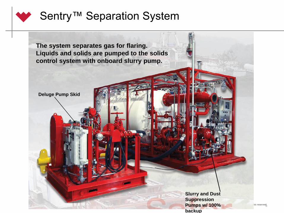
Sentry™ Separation System
5
The system separates gas for flaring.
Liquids and solids are pumped to the solids
control system with onboard slurry pump.
Slurry and Dust
Suppression
Pumps w/ 100%
backup
Deluge Pump Skid
© 2012 Weatherford. All rights reserved. © 2012 Weatherford. All rights reserved.
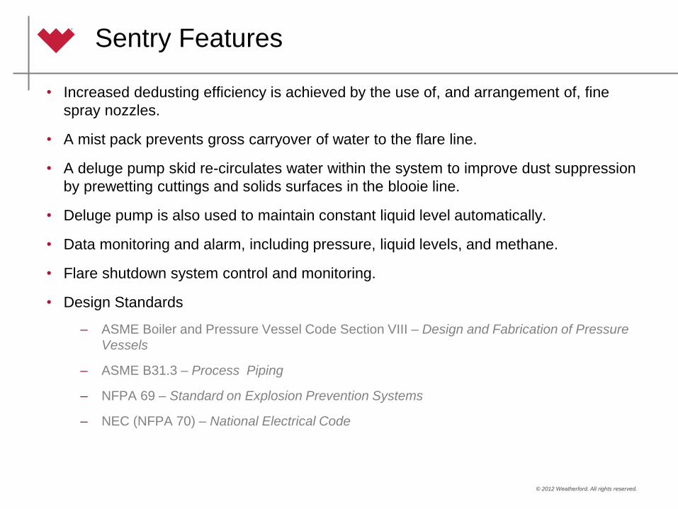
Sentry Features
• Increased dedusting efficiency is achieved by the use of, and arrangement of, fine
spray nozzles.
• A mist pack prevents gross carryover of water to the flare line.
• A deluge pump skid re-circulates water within the system to improve dust suppression
by prewetting cuttings and solids surfaces in the blooie line.
• Deluge pump is also used to maintain constant liquid level automatically.
• Data monitoring and alarm, including pressure, liquid levels, and methane.
• Flare shutdown system control and monitoring.
• Design Standards
– ASME Boiler and Pressure Vessel Code Section VIII – Design and Fabrication of Pressure
Vessels
– ASME B31.3 – Process Piping
– NFPA 69 – Standard on Explosion Prevention Systems
– NEC (NFPA 70) – National Electrical Code

© 2012 Weatherford. All rights reserved.
7
• Bore Volume: 250 ft3/hr
• Slurry Volume: 1445 ft3/hr (180 gpm)
• Total Gas Returns: 6000 scfm
• Unload rate: 550 gpm (785 bbl/hr)*
• Surge capacity: 32 bbl
*350 gpm if sparge is active.
Performance Specifications
© 2012 Weatherford. All rights reserved.
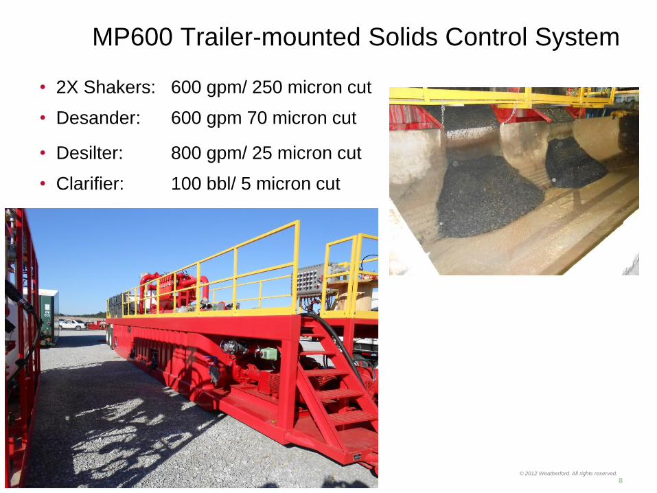
• 2X Shakers: 600 gpm/ 250 micron cut
• Desander: 600 gpm 70 micron cut
• Desilter: 800 gpm/ 25 micron cut
• Clarifier: 100 bbl/ 5 micron cut
8
MP600 Trailer-mounted Solids Control System
© 2012 Weatherford. All rights reserved. © 2012 Weatherford. All rights reserved.
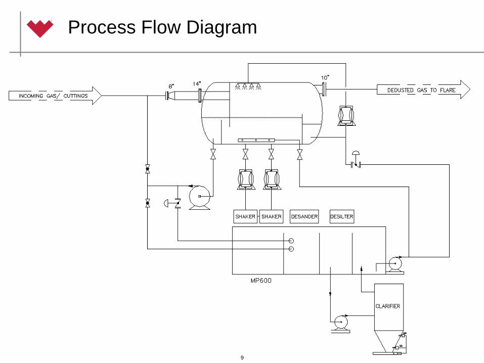
Process Flow Diagram
9

© 2012 Weatherford. All rights reserved. © 2012 Weatherford. All rights reserved.
Field Trials
• 18550’ of hole drilled to date (mist and dust)
• Three wells in Fayetteville Shale
– 1@ 8-7/8” from 1050’ to 3900’
– 2@ 12.45 to 1050’
• Two wells in Marcellus Shale (mobilizing for third)
– 20” to 325’, 15” to 530’, 10-7/8” to 2280’, 7-7/8” to 6800’
• Typical rates of 125 ft^3/hr with some stands as high as 220 ft^3/hr
bore rate.
• Met contractual KPI’s with minor challenges leading to lessons
learned.
10

© 2012 Weatherford. All rights reserved. © 2012 Weatherford. All rights reserved.
11

© 2012 Weatherford. All rights reserved. © 2012 Weatherford. All rights reserved.
12

© 2012 Weatherford. All rights reserved. © 2012 Weatherford. All rights reserved.
13

© 2012 Weatherford. All rights reserved. © 2012 Weatherford. All rights reserved.
14

© 2012 Weatherford. All rights reserved. © 2012 Weatherford. All rights reserved.
Questions?