RDS-CAA Qualification and Programming Primer. 2 of 36RDS-CAA Primer The MasterProbe will have to be...
36
RDS-CAA Qualification and Programming Primer
-
Upload
joelle-painter -
Category
Documents
-
view
229 -
download
0
Transcript of RDS-CAA Qualification and Programming Primer. 2 of 36RDS-CAA Primer The MasterProbe will have to be...
RDS-CAA Qualification and Programming Primer
2 of 36RDS-CAA Primer
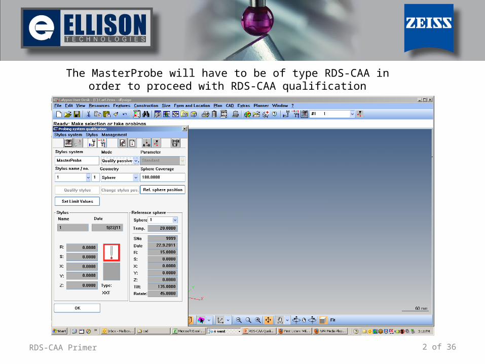
The MasterProbe will have to be of type RDS-CAA in order to proceed with RDS-CAA qualification
3 of 36RDS-CAA Primer
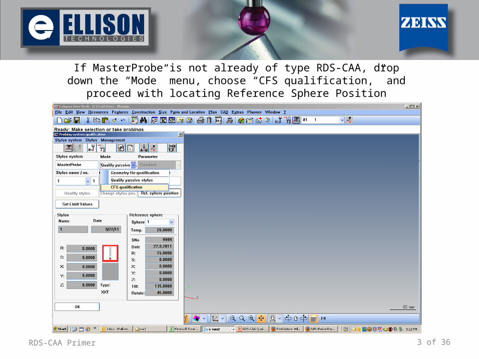
If MasterProbe is not already of type RDS-CAA, drop down the “Mode” menu, choose “CFS qualification,” and proceed with locating Reference
Sphere Position
4 of 36RDS-CAA Primer
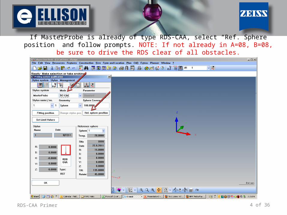
If MasterProbe is already of type RDS-CAA, select “Ref. Sphere position” and follow prompts. NOTE: If not already in A=08, B=08, be sure to drive the RDS clear of all obstacles.
5 of 36RDS-CAA Primer
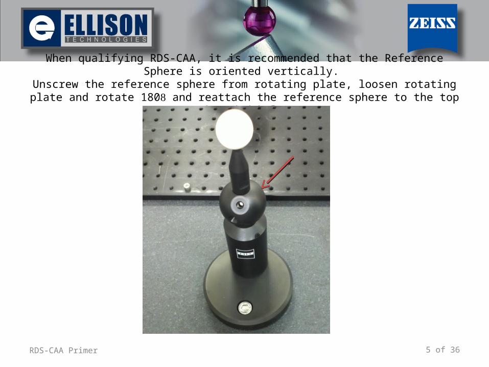
When qualifying RDS-CAA, it is recommended that the Reference Sphere is oriented vertically. Unscrew the reference sphere from rotating plate, loosen rotating plate and rotate 180 and
reattach the reference sphere to the top threaded hole.
6 of 36RDS-CAA Primer
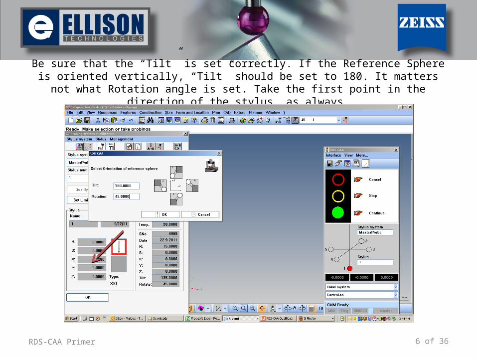
Be sure that the “Tilt” is set correctly. If the Reference Sphere is oriented vertically, “Tilt” should be set to 180. It matters not what Rotation angle is set. Take the first point in the
direction of the stylus, as always.
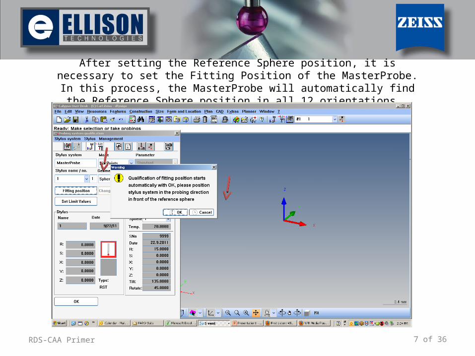
7 of 36RDS-CAA Primer
After setting the Reference Sphere position, it is necessary to set the Fitting Position of the MasterProbe. In this process, the MasterProbe will
automatically find the Reference Sphere position in all 12 orientations.
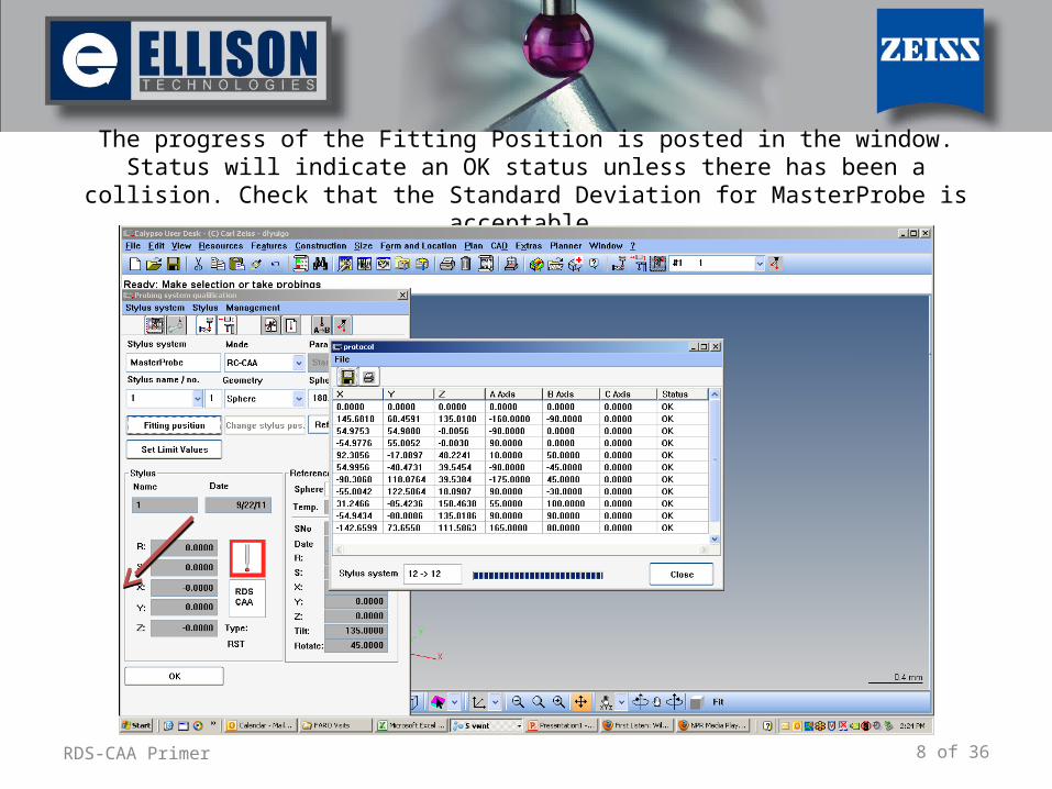
8 of 36RDS-CAA Primer
The progress of the Fitting Position is posted in the window. Status will indicate an OK status unless there has been a collision. Check that the Standard Deviation for
MasterProbe is acceptable.
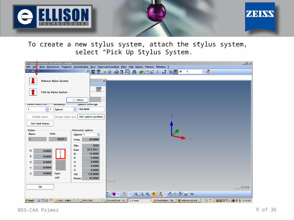
9 of 36RDS-CAA Primer
To create a new stylus system, attach the stylus system, select “Pick Up Stylus System.”
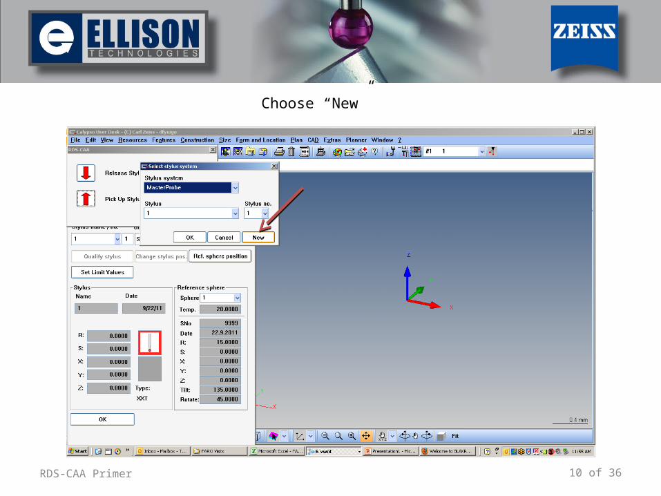
10 of 36RDS-CAA Primer
Choose “New”
11 of 36RDS-CAA Primer
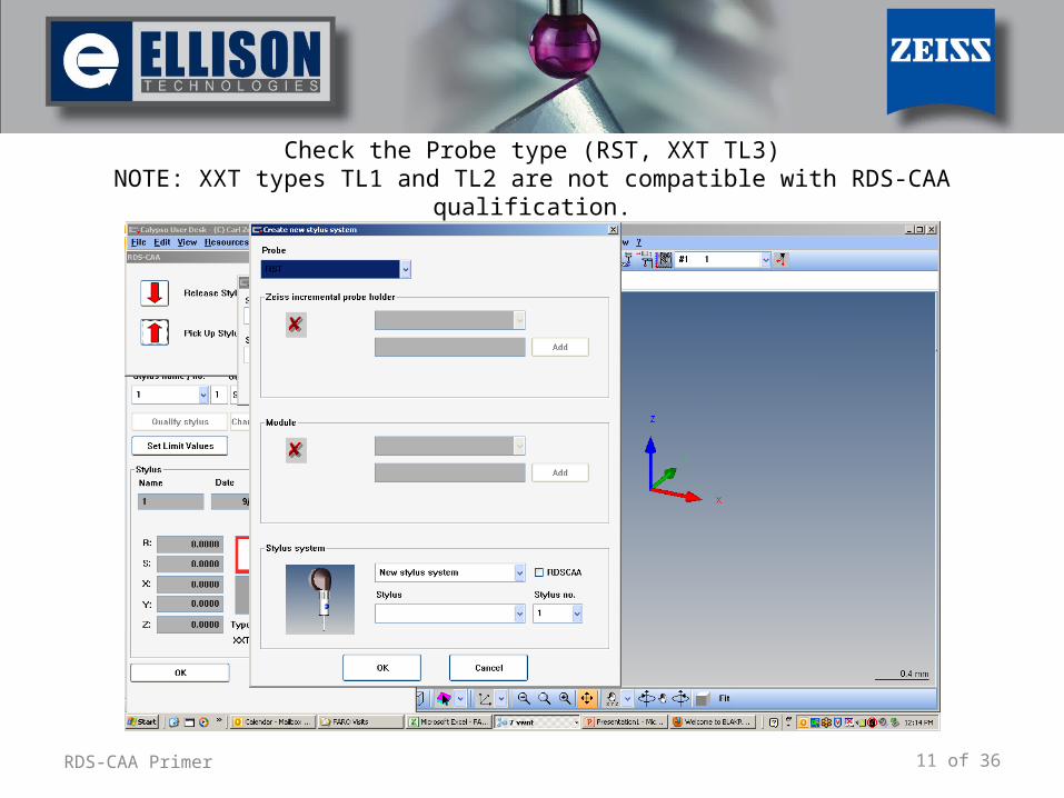
Check the Probe type (RST, XXT TL3)NOTE: XXT types TL1 and TL2 are not compatible with RDS-CAA qualification.
12 of 36RDS-CAA Primer
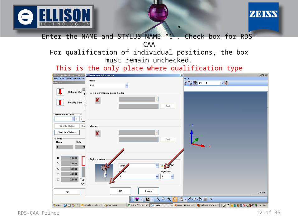
Enter the NAME and STYLUS NAME “1”. Check box for RDS-CAAFor qualification of individual positions, the box must remain unchecked.This is the only place where qualification type (normal or RDS-CAA) may
be set
13 of 36RDS-CAA Primer
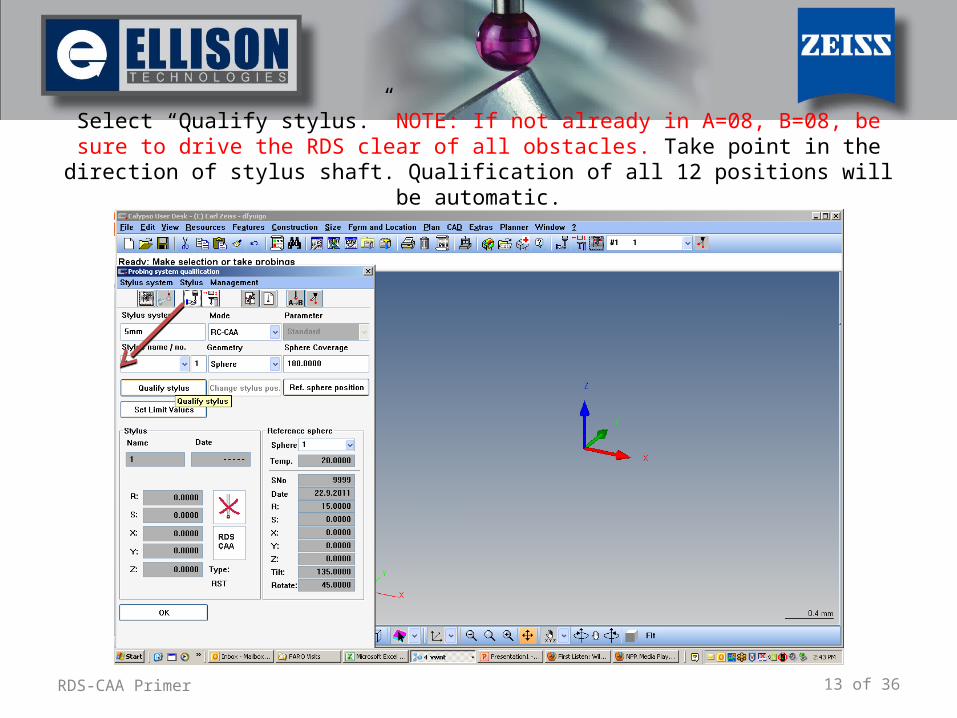
Select “Qualify stylus.” NOTE: If not already in A=08, B=08, be sure to drive the RDS clear of all obstacles. Take point in the direction of stylus shaft. Qualification of all 12
positions will be automatic.
14 of 36RDS-CAA Primer
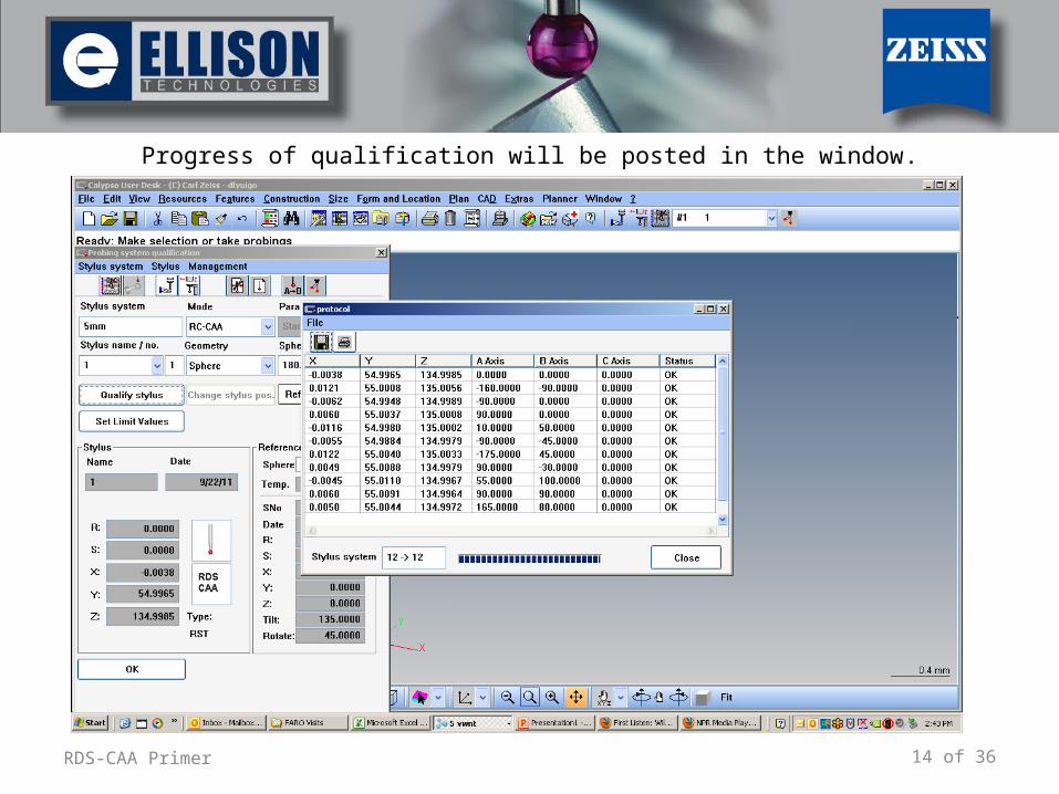
Progress of qualification will be posted in the window.
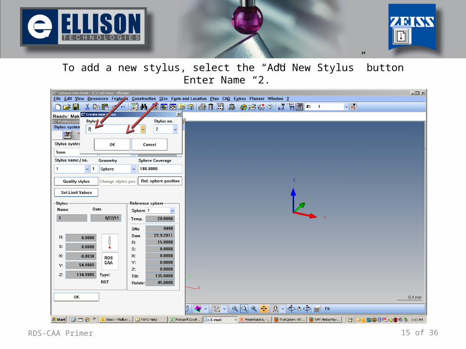
15 of 36RDS-CAA Primer
To add a new stylus, select the “Add New Stylus” buttonEnter Name “2.”
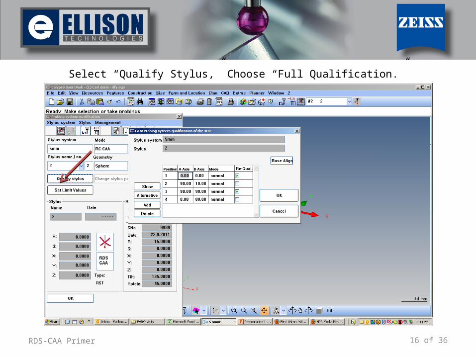
16 of 36RDS-CAA Primer
Select “Qualify Stylus,” Choose “Full Qualification.”
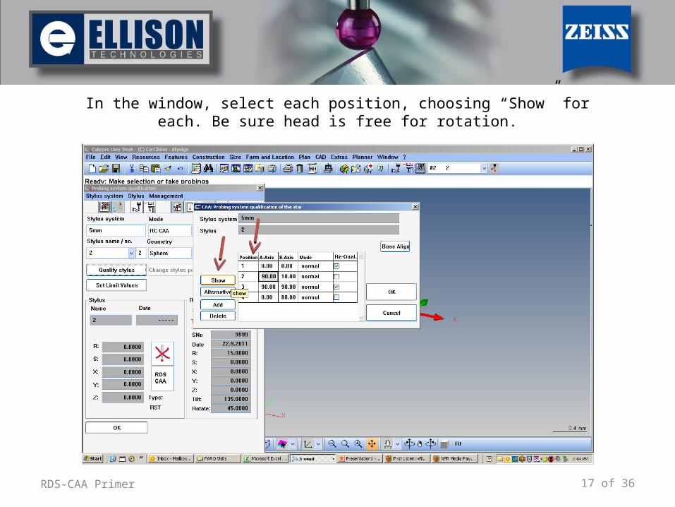
17 of 36RDS-CAA Primer
In the window, select each position, choosing “Show” for each. Be sure head is free for rotation.
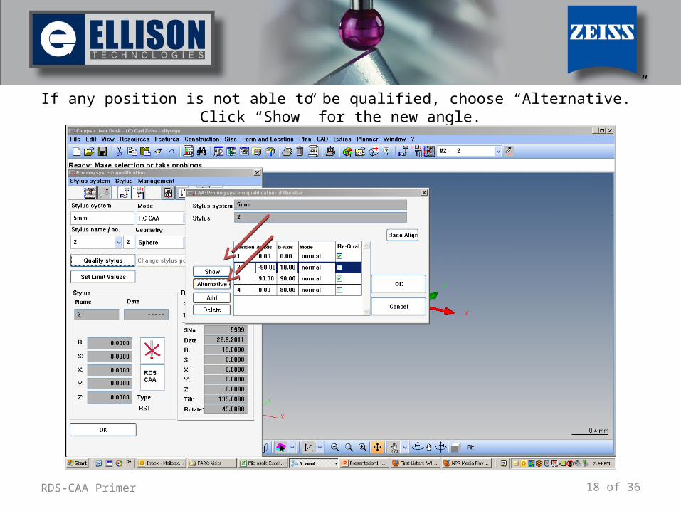
18 of 36RDS-CAA Primer
If any position is not able to be qualified, choose “Alternative.” Click “Show” for the new angle.
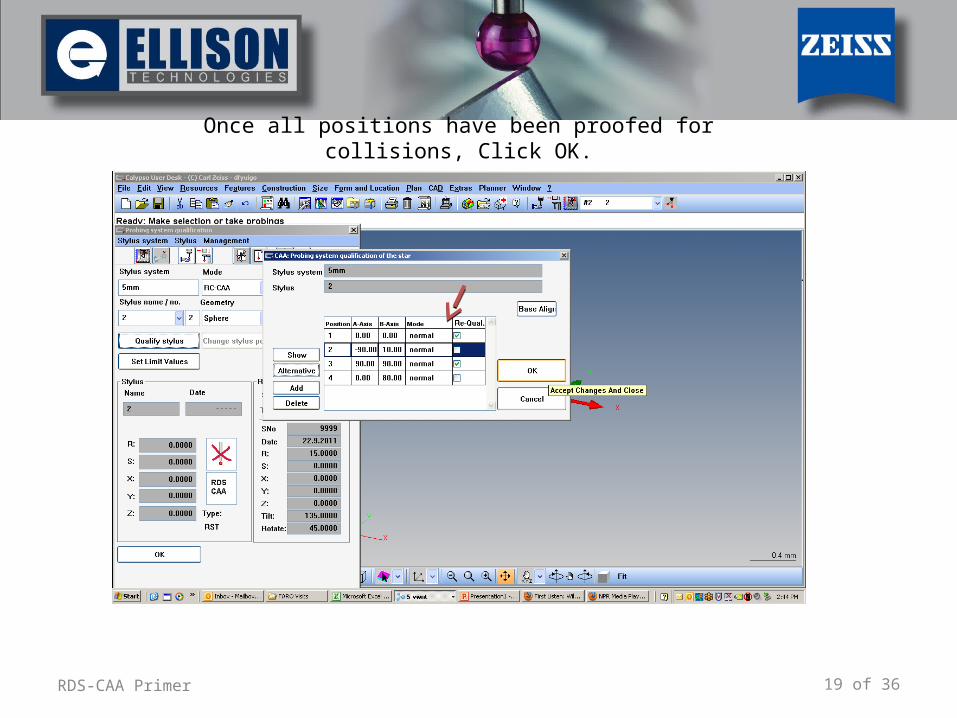
19 of 36RDS-CAA Primer
Once all positions have been proofed for collisions, Click OK.
20 of 36RDS-CAA Primer
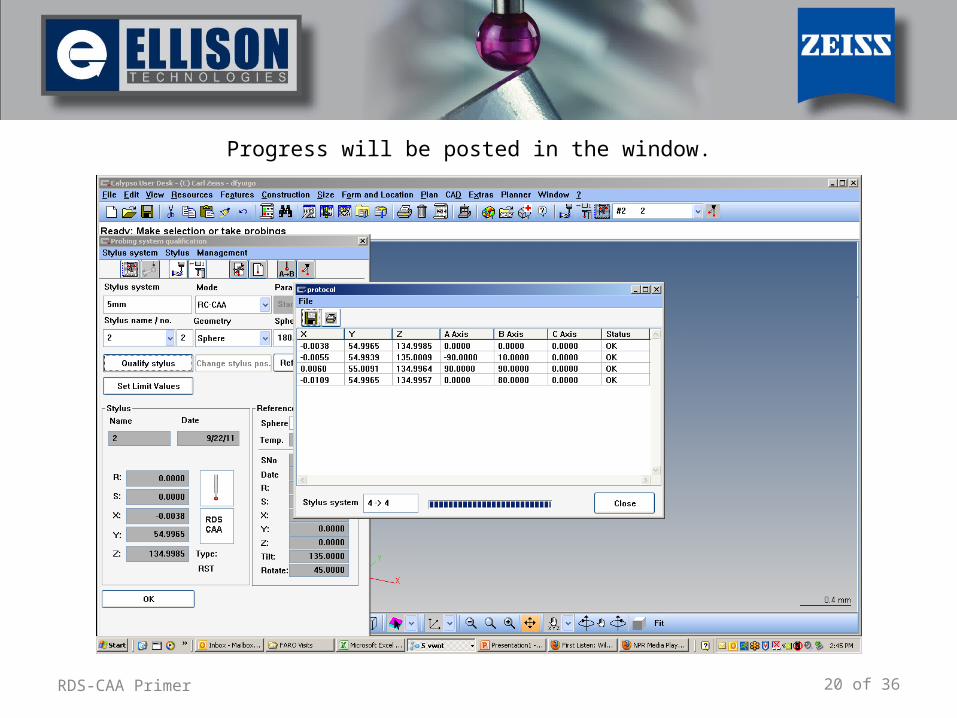
Progress will be posted in the window.
21 of 36RDS-CAA Primer
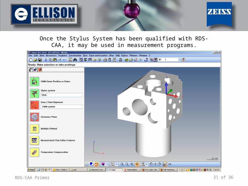
Once the Stylus System has been qualified with RDS-CAA, it may be used in measurement programs.
22 of 36RDS-CAA Primer
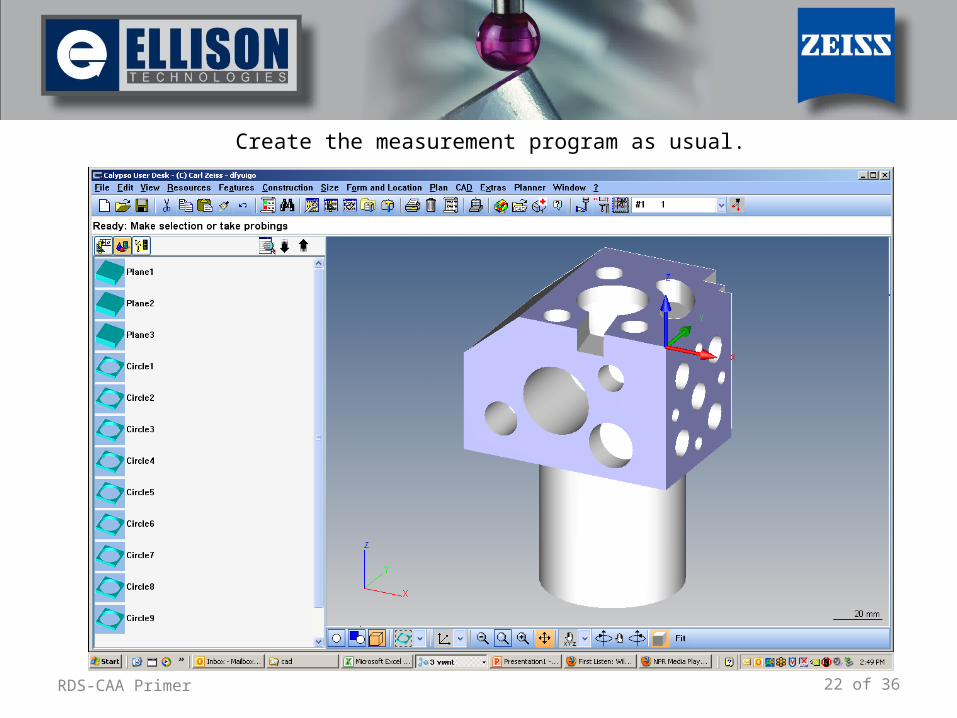
Create the measurement program as usual.
23 of 36RDS-CAA Primer
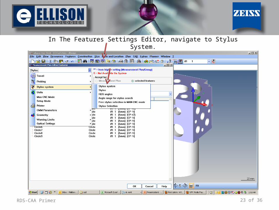
In The Features Settings Editor, navigate to Stylus System.
24 of 36RDS-CAA Primer
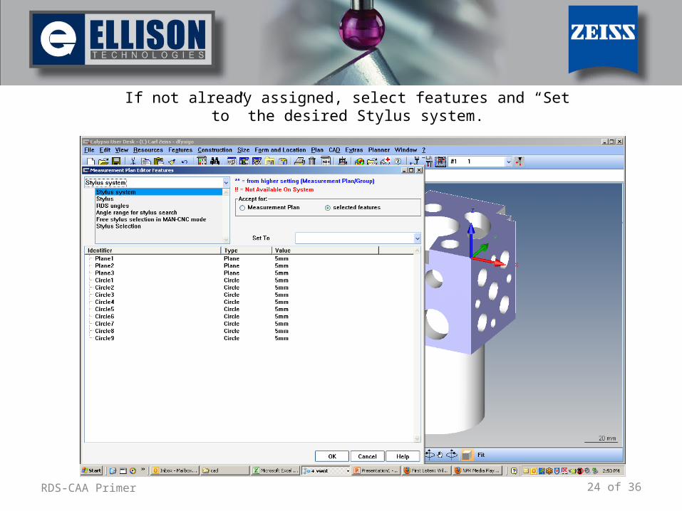
If not already assigned, select features and “Set to” the desired Stylus system.
25 of 36RDS-CAA Primer
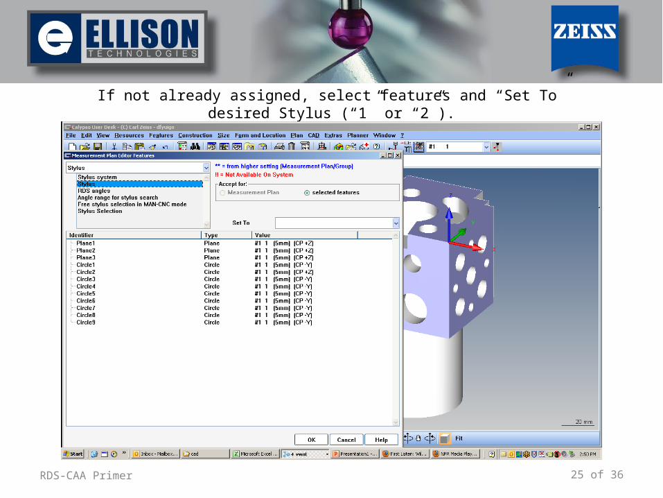
If not already assigned, select features and “Set To” desired Stylus (“1” or “2”).
26 of 36RDS-CAA Primer
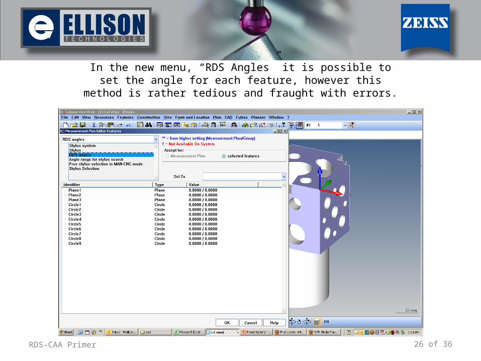
In the new menu, “RDS Angles” it is possible to set the angle for each feature, however this method is rather tedious and fraught
with errors.
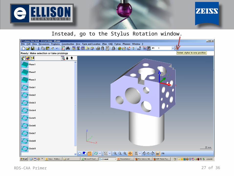
27 of 36RDS-CAA Primer
Instead, go to the Stylus Rotation window.
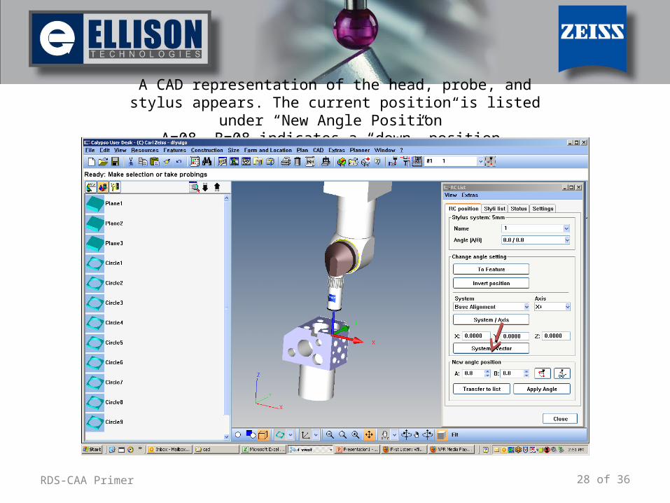
28 of 36RDS-CAA Primer
A CAD representation of the head, probe, and stylus appears. The current position is listed under “New Angle Position”
A=08, B=08 indicates a “down” position.
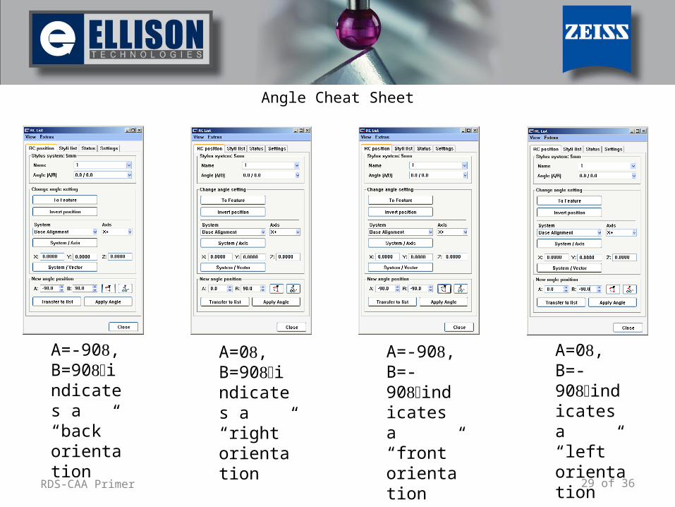
29 of 36RDS-CAA Primer
Angle Cheat Sheet
A=-90, B=90indicates a “back” orientation
A=0, B=90indicates a “right” orientation
A=-90, B=-90indicates a “front” orientation
A=0, B=-90indicates a “left” orientation
30 of 36RDS-CAA Primer
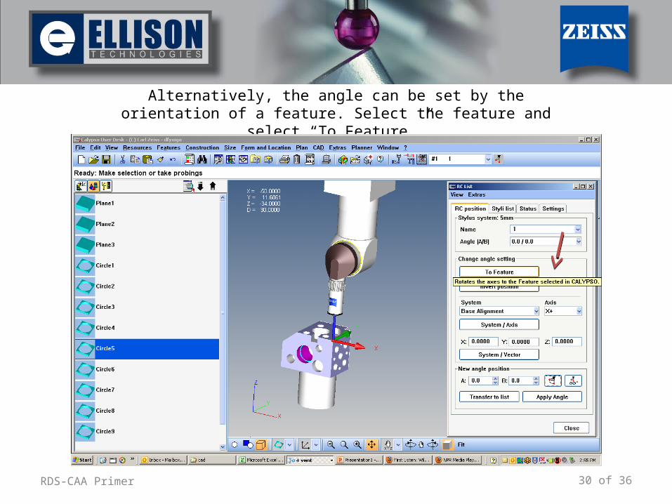
Alternatively, the angle can be set by the orientation of a feature. Select the feature and select “To Feature.”
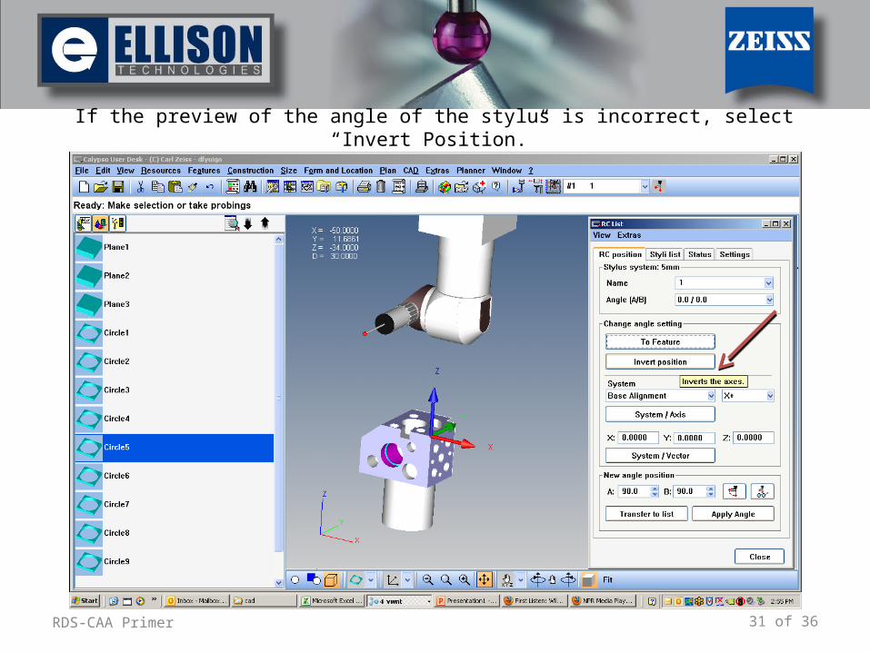
31 of 36RDS-CAA Primer
If the preview of the angle of the stylus is incorrect, select “Invert Position.”
32 of 36RDS-CAA Primer
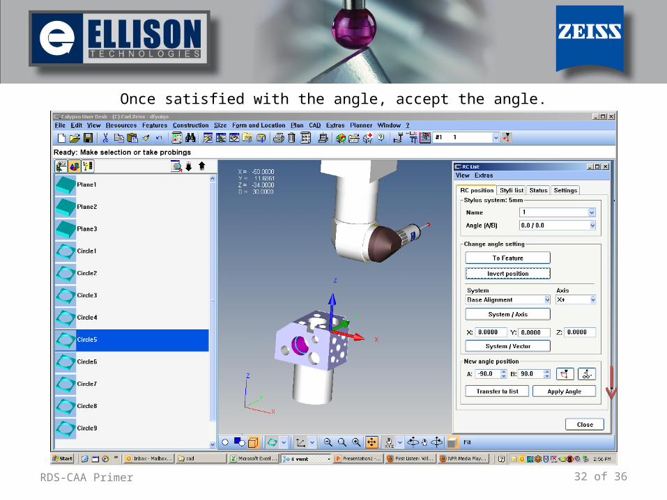
Once satisfied with the angle, accept the angle.
33 of 36RDS-CAA Primer
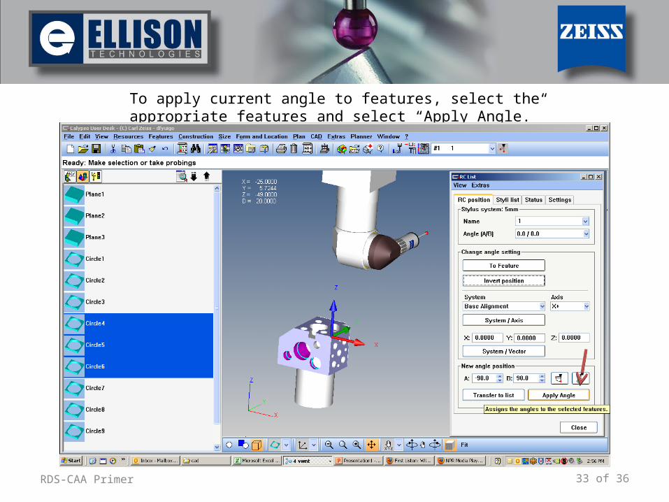
To apply current angle to features, select the appropriate features and select “Apply Angle.”
34 of 36RDS-CAA Primer
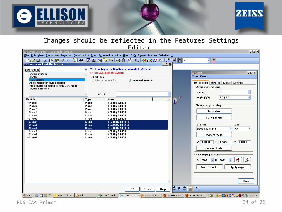
Changes should be reflected in the Features Settings Editor.
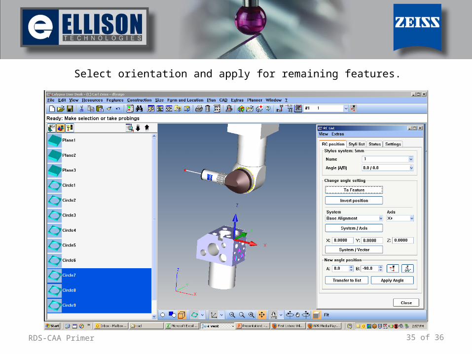
35 of 36RDS-CAA Primer
Select orientation and apply for remaining features.
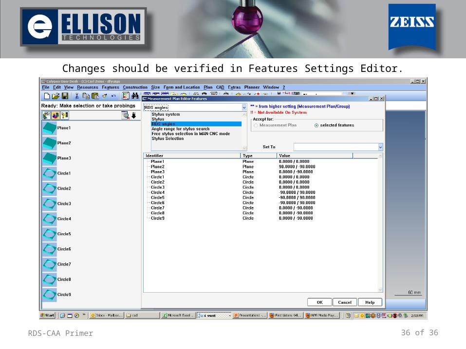
36 of 36RDS-CAA Primer
Changes should be verified in Features Settings Editor.