Rds Manual
15
RDM Splitters Models RDS4 and RDS8 User Manual www.enttec.com June 2007
-
Upload
bogdan-calcan -
Category
Documents
-
view
236 -
download
0
Transcript of Rds Manual
8/3/2019 Rds Manual
http://slidepdf.com/reader/full/rds-manual 1/15
RDM SplittersModels RDS4 and RDS8
User Manual
www.enttec.com
June 2007
8/3/2019 Rds Manual
http://slidepdf.com/reader/full/rds-manual 2/15
Package Contents
Your RDS4 package should contain these items:
• RDS4 (Part No. 70037)• IEC Power Cord (Australia only)
•
This user manual
Your RDS8 package should contain these items:• RDS8 (Part No. 70036)• IEC Power Cord (Australia only)
• This user manual
If any item is missing or damaged, please contact your supplier
immediately.
2 RDM Splitters Manual
8/3/2019 Rds Manual
http://slidepdf.com/reader/full/rds-manual 3/15
RDS 4 and RDS 8User Manual
Firmware V1.0
Table of Contents
Models RDS4 and RDS8......................................................... 1
Warranty.......................................................................................... 4Contacting ENTTEC....................................................................... 4
Getting Support................................................................................ 4
Getting to know your RDS4 or RDS8 ............................................ 5Features............................................................................................ 5Layout.............................................................................................. 6Connecting the RDS4 or RDS8....................................................... 7
Power supply........................................................................... 8DMX Out................................................................................. 8
DMX In.................................................................................... 8
Electrical Isolation................................................................... 8Powering up the RDS4 or RDS8................................................. 9Using the RDS4 or RDS8............................................................... 9
Normal Mode...............................................................................9Filtered Mode............................................................................ 10
When to use Filtered Mode: ................................................. 10 Bypassed Mode..........................................................................10
.................................................................................................. 10
When to use the Bypass Mode: ............................................ 11
Appendix 1 - Connector Pinouts................................................ 12 DMX OUT.................................................................................12
DMX IN.....................................................................................12Appendix 2 - FCC Declaration.................................................... 13
Federal Communications Commission (FCC) Declarationof Conformity.................................................................. 13
Appendix 3 - EEC Declaration.................................................... 15
3
8/3/2019 Rds Manual
http://slidepdf.com/reader/full/rds-manual 4/15
Warranty
ENTTEC warrants that the product that it manufactures will be
free from defects in materials and workmanship for a period of one
year from the date of shipment from an authorised ENTTECwholesaler. If the device proves defective within the warranty period, ENTTEC will repair or replace at its sole discretion, thedefective hardware. If the failure is due to an operator error, the
user accepts the responsibility to pay any costs incurred in thediagnosis of the hardware, parts or shipping from our service
facility.
ENTTEC makes no warranty of any kind, express or implied,including without limitation the implied warranties of
merchantability and fitness for a particular purpose. In no
event shall ENTTEC be liable for indirect, special or
consequential damages.
Opening the case of the unit voids the warranty as described
above.
Contacting ENTTEC
Email: [email protected]
Telephone: +61 3 9819 2433 GMT+10Facsimile: +61 3 9819 2733
Postal Address: ENTTEC Pty LtdPO Box 282
KewVic 3101 Australia
Getting Support
If you require support for the RDS4 or RDS8 please visit the
Support area of our website at www.enttec.com. There you can fillout a support request ticket for prompt assistance with your
enquiry.
4 RDM Splitters Manual
8/3/2019 Rds Manual
http://slidepdf.com/reader/full/rds-manual 5/15
Getting to know your RDS4 or RDS8
Thank you for purchasing the RDS4 or RDS8. At Enttec we are proud of our products and we hope you will enjoy using them as
much as we enjoy designing and building them.
The RDS4 and the RDS8 are hubs/splitters which are built withRemote Device Management data in mind. They can be used as
the backbone for creating a bidirectional DMX512 control network where a controller that is RDM-enabled, and a number of
DMX512 fixtures or dimmers (with or without the RDMtechnology) can communicate with each other. The RDS4 andRDS8 comply with the newest industry standard DMX512-A and
RDM protocols (American National Standard E1.20-2006) andwill work seamlessly with other devices that comply with those
standards as well.
Features
The RDS4 (or RDS8) provides:• A full 512 addresses of DMX (1 universe) can be transmitted
from controller out to devices, and messages from those devices
sent back.• One input which is the Male 5-pin and 4 outputs (8 in RDS8)
which are Female 5-pin style.• Two buttons which allow user to select different features: RDM
enabled, RDM filtered, and Bypass.
5

8/3/2019 Rds Manual
http://slidepdf.com/reader/full/rds-manual 6/15
Layout
The RDS4 case is 1.75” (44.45mm) in height, 11.82” (300mm)wide and 4.53” (115mm) deep. This makes it easy to put on a
tabletop or shelf, and with an optional mounting bracket you can place it on a truss or pipe.
RDS4 front panel
The RDS8 case is made for rack mounting in a 1unit high slot.It is 17” (432mm) wide not including rack mount ears, 1.72”
(43.6mm) high and 4.36” (111mm) deep.
RDS8 front panel
Close Up of Front Panel
1 Signal Flow Diagram
Shows how switching works for quick reference in the field.
2 LED Status Display
Indicates operational status.
• SYSTEM OK: LED flashes twice per second (2Hz) whenunit is healthy and not bypassed.
• DMX: LED flashes at 8Hz each time a DMX packet is
received, and not bypassed.• RDM: LED flashes at 8Hz each time a RDM packet is
6 RDM Splitters Manual
8/3/2019 Rds Manual
http://slidepdf.com/reader/full/rds-manual 7/15
received and neither bypassed nor filtered.• BYPASS Lights up in a constant fashion when Bypass mode
is enabled. (See page 10 for details about this mode.)
3 Bypass ButtonThis button allows the splitter to work in a mode which iscalled “Bypass” because all RDM functionality is disabled; the
microprocessor which handles such tasks is not in use, and youcan think of the bypassed splitter as working the same way as
any typical non-RDM splitter would. For more information onthis mode, see page 10.
4 RDM Filter Button
This button chooses between a normal operation of the splitter,which is to facilitate the passing of RDM messages in both
directions, and a filtration mode. That means any legacyfixtures which respond poorly to the presence of RDM signalscan be protected from them, eliminating flicker or other
unwelcome behavior.
5 XLR 5pin Male
DMX512 Input. Connects to your DMX512 controller. If a
proper DMX signal is being received, the DMX LED will flashas described above.
6 XLR 5pin Female (not shown in closeup)DMX512 Output. Connects up to 4 (RDS4) or 8 (RDS8) cables
which in turn may connect to one or more (up to 32 standard)DMX512 devices. Additional RDS splitters may be used toconnect to more devices or split into more cable runs for
convenience of wiring.
Connecting the RDS4 or RDS8
Installation of an RDS device is as simple as plugging in the mains
power and connecting your controller to the male input and your fixtures or dimmers to the females. If you wish to make or break
7
8/3/2019 Rds Manual
http://slidepdf.com/reader/full/rds-manual 8/15
connections while the device is powered on, there is nothing wrongwith this from the RDS device's point of view. (Some
manufacturers of fixtures may specify otherwise but the normal procedure would be that sequence of plugging shouldn't matter.)
Power supply
The RDS4 and RDS8 have an autoswitching power supply so thatthe mains can be anything from 96 to 240 volts, with 50-60 Hz
AC. Connection to power turns the unit on. There is no power switch to be toggled.
DMX OutThe DMX Out sockets allow you to connect the devices you arecontrolling to RDS splitter. Please consult standard DMX512
wiring practice (based on RS485 serial protocol if that is morefamiliar to you) for advice on how to arrange a DMX512 network.
A good example of this can be found at wikipedia.org, bysearching for “DMX512”.
DMX In
The DMX In socket is for making a connection to your controller or to other RDS devices that are between the controller and the
RDS device being installed.
Electrical Isolation
The RDS4 and the RDS8 are constructed with state of the artisolation placed next to the inputs and all the outputs. That means
you have 1500V worth of protection against harmful surges andtransient spikes from output to output, as well as between any of the branches and the controller plugged to the input. Many RDM
capable splitters do not go to these lengths to protect your equipment, but Enttec takes this issue very seriously and provides
the most comprehensive strategy practical for safely isolating the
DMX lines.
8 RDM Splitters Manual
8/3/2019 Rds Manual
http://slidepdf.com/reader/full/rds-manual 9/15
Powering up the RDS4 or RDS8
As there is no power switch, when the RDS4 or RDS8 is plugged
in, it should be powered on. You can confirm this by noticing thatwhen first connecting it, the SYSTEM OK LED status indicator
light should come on and then blink regularly.
Using the RDS4 or RDS8
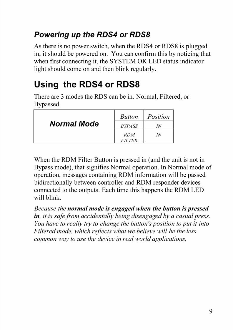
There are 3 modes the RDS can be in. Normal, Filtered, or
Bypassed.
Normal Mode Button Position BYPASS IN
RDM FILTER
IN
When the RDM Filter Button is pressed in (and the unit is not in
Bypass mode), that signifies Normal operation. In Normal mode of
operation, messages containing RDM information will be passed bidirectionally between controller and RDM responder devicesconnected to the outputs. Each time this happens the RDM LED
will blink.
Because the normal mode is engaged when the button is pressed
in , it is safe from accidentally being disengaged by a casual press.You have to really try to change the button's position to put it into
Filtered mode, which reflects what we believe will be the lesscommon way to use the device in real world applications.
9
8/3/2019 Rds Manual
http://slidepdf.com/reader/full/rds-manual 10/15
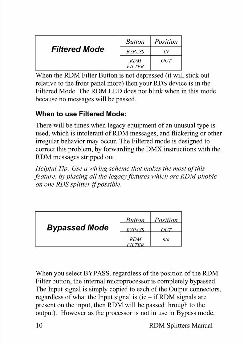
Filtered Mode Button Position
BYPASS IN
RDM FILTER
OUT
When the RDM Filter Button is not depressed (it will stick out
relative to the front panel more) then your RDS device is in theFiltered Mode. The RDM LED does not blink when in this mode
because no messages will be passed.
When to use Filtered Mode:
There will be times when legacy equipment of an unusual type is
used, which is intolerant of RDM messages, and flickering or other irregular behavior may occur. The Filtered mode is designed to
correct this problem, by forwarding the DMX instructions with theRDM messages stripped out.
Helpful Tip: Use a wiring scheme that makes the most of this feature, by placing all the legacy fixtures which are RDM-phobicon one RDS splitter if possible.
Bypassed Mode Button Position
BYPASS OUT
RDM FILTER n/a
When you select BYPASS, regardless of the position of the RDMFilter button, the internal microprocessor is completely bypassed.
The Input signal is simply copied to each of the Output connectors,regardless of what the Input signal is (ie – if RDM signals are
present on the input, then RDM will be passed through to theoutput). However as the processor is not in use in Bypass mode,
10 RDM Splitters Manual
8/3/2019 Rds Manual
http://slidepdf.com/reader/full/rds-manual 11/15
no RDM signals will be passed back from the fixtures to thecontroller.
The BYPASS LED will light up to indicate that you're in this state, but none of the other LEDs (System OK, DMX etc) will beilluminated, as the processor is no longer monitoring the status of
the signal being received. The outputs are still fully electricallyisolated from each other and from the input.
To prevent BYPASS Mode being accidentally engaged, the
BYPASS switch is designed to be OFF when depressed, or sittingflush with the outer case of the RDS splitter. To enter BYPASSMode, the user must press and release the button, so it protudes
from case. The BYPASS LED will illuminate immediately.
When to use the Bypass Mode:
In Bypass Mode the RDS provides fully isolated outputs that arereplicated from the input signal, so it is suitable for use withcompletely non-RDM networks (ie – both console and fixtures
running standard DMX-512 only) or even non-DMX protocols,such as the High End, Martin or NSI protocols in use in some older
equipment.
11

8/3/2019 Rds Manual
http://slidepdf.com/reader/full/rds-manual 12/15
Appendix 1 - Connector PinoutsDMX OUT
Pin 1 Ground
Pin 2 Data -
Pin 3 Data +
Pin 4 NC
Pin 5 NC
DMX IN
Pin 1 Ground
Pin 2 Data -
Pin 3 Data +
Pin 4 NC
Pin 5 NC
12 RDM Splitters Manual
8/3/2019 Rds Manual
http://slidepdf.com/reader/full/rds-manual 13/15
Appendix 2 - FCC Declaration
Federal Communications Commission (FCC)
Declaration of Conformity
Responsible Party: ENTTEC Pty Ltd
PO Box 282,Kew, Vic, 3101
Australia
declares that the products RDS4 and RDS8 comply with Part 15
of the FCC Rules. Operation is subject to the following twoconditions: (1) This device may not cause harmful interference,and (2) this device must accept any interference received,
including interference that may cause undesired operation.
This equipment has been tested and found to comply with thelimits for a Class B digital device, pursuant to Part 15 of the FCCrules. These limits are designed to provide reasonable protection
against harmful interference in a residential installation. Thisequipment generates, uses and can radiate radio frequency energy
and, if not installed and used in accordance with the instructions,may cause harmful interference to radio communications.
However, there is no guarantee that interference will not occur in a particular installation. If this equipment does cause harmful
interference to radio or television reception, which can be
determined by turning the equipment off and on, the user isencouraged to try to correct the interference by one or more of thefollowing measures:
- Reorient or relocate the receiving antenna.
- Increase the separation between the equipment and thereceiver.
- Connect the equipment into an outlet on a circuit
13
8/3/2019 Rds Manual
http://slidepdf.com/reader/full/rds-manual 14/15
different from that to which the receiver is connected.
- Consult the dealer or an experienced radio/TVtechnician for help.
* In order to maintain compliance with FCC regulationsshielded cables must be used with this equipment. Operation with
non-approved equipment or unshielded cables is likely to result ininterference to radio and television reception.
14 RDM Splitters Manual
8/3/2019 Rds Manual
http://slidepdf.com/reader/full/rds-manual 15/15
Appendix 3 - EEC Declaration
WeENTTEC Pty Ltd
PO Box 282,Kew, Vic, 3101
Australia
declare under our sole responsibility that out products RDS4 andRDS8 conform to the requirements of Council Directives
89/336/EEC and 73/23/EEC and therefore complies with therequirements of Council Directive 73/23/EEC, (The Low VoltageDirective) on the harmonisation of the laws of Member States
relating to electrical equipment designed for use within certainvoltage limits as amended by Article 13 of Council Directive
93/68/EEC
• EN 55103-1• EN 50103-2
• EN 60065/AS 3650
Signed Nicolas Moreau
Date: 4/4/2007
Position: Technical Director
15
![RDS 323 Restorative Dental Sciences [ RDS]](https://static.fdocuments.us/doc/165x107/6235ee36aafa9c66c73cc0cf/rds-323-restorative-dental-sciences-rds.jpg)