PTCC-01-ADV - VIGO
25
PTCC-01-ADV Programmable ”SMART” TEC Controller user's guide
Transcript of PTCC-01-ADV - VIGO

PTCC-01-ADVProgrammable ”SMART” TEC Controller
user's guide

Table of ContentsWarranty........................................................................................................................................................................... 31. Description.................................................................................................................................................................... 42. Features........................................................................................................................................................................ 43. PTCC-01-ADV Physical Description............................................................................................................................. 4
3.1. Physical Dimensions [mm].................................................................................................................................... 43.2. The Front Panel at a Glance................................................................................................................................. 53.3. The Back Panel at a Glance................................................................................................................................. 53.4. The Top Panel (Keyboard) at a Glance................................................................................................................. 53.5. The Bottom Panel at a Glance.............................................................................................................................. 5
4. PTCC-01-ADV Theory of Operation.............................................................................................................................. 65. PTCC-01-ADV Menu Structure..................................................................................................................................... 66. Detailed Description of the Menu.................................................................................................................................. 8
6.1. Quick wiew of the most important parameters......................................................................................................86.2. PTCC & IR module information............................................................................................................................. 86.3. PTCC Monitor....................................................................................................................................................... 96.4. PTCC Settings.................................................................................................................................................... 126.5. PIP Monitor......................................................................................................................................................... 146.6. PIP advanced settings........................................................................................................................................ 176.7. Load defaults...................................................................................................................................................... 20
7. Example - How to Move About Menu..........................................................................................................................208. PC Software Description "Smart Manager"................................................................................................................. 22
8.1. Program Description........................................................................................................................................... 228.2. Smart Manager First Use.................................................................................................................................... 238.3. Update Procedure............................................................................................................................................... 24
9. Safety Instructions....................................................................................................................................................... 25
VIGO System S.A. 129/133 Poznanska St., 05-850 Ozarow Mazowiecki, Poland, tel.: +48 22 733 54 06, fax: +48 22 733 54 26, email: [email protected] 2Please note: the information contained in the document is subject to change without further notification. VIGO System S.A. reserves the right to alter the performance and any resulting specifications. VS 15.05.15 KO

PTCC-01-ADV user's guide
WarrantyVIGO System S.A. hereby represents and warrants all Products manufactured by VIGO and sold hereunder to be free from defects in workmanshipor material during a period of twelve (12) months from the date of delivery save for products for which a special warranty is given. If any Productproves however to be defective in workmanship or material within the period herein provided VIGO System undertakes to the exclusion of any otherremedy to repair or at its own option replace the defective Product or part thereof free of charge and otherwise on the same conditions as for theoriginal Product or part without extension to original warranty time. Defective parts replaced in accordance with this clause shall be placedat the disposal of VIGO.
VIGO also warrants the quality of all repair and service works performed by its employees to products sold by it. In case the repair or service worksshould appear inadequate or faulty and should this cause malfunction or nonfunctioning of the product to which the service was performed VIGOshall at its free option either repair or have repaired or replace the product in question. The working hours used by employees of VIGO for suchrepair or replacement shall be free of charge to the client. This service warranty shall be valid for a period of six (6) months from the date the servicemeasures were completed.
This warranty is however subject to following conditions:• a substantiated written claim as to any alleged defects shall have been received by VIGO System within thirty (30) days after the defect or
fault became known or occurred,and
• the allegedly defective Product or part shall, should VIGO so require, be sent to the works of VIGO or to such other place as VIGO mayindicate in writing, freight and insurance prepaid, properly packed and labeled.
This warranty does not however apply when the defect has been caused through1. normal wear and tear or accident;2. misuse or other unsuitable or unauthorized use of the Product or negligence or error in storing, maintaining or in handling the Product or
any equipment thereof;3. wrong installation, assembly or failure to service the Product or otherwise follow VIGO's service instructions including any repairs or
installation or assembly or service made by unauthorized personnel not approved by VIGO or replacements with parts not manufacturedor supplied by VIGO;
4. modifications or changes of the Product as well as any adding to it without VIGO's prior authorization;5. burned active element by irradiation above damage thresholds;6. electrostatic discharges;7. improper detector bias;8. improper TE cooler bias (TE cooler damage or active element overheating);9. other factors dependent on the Customer or a third party.
Notwithstanding the aforesaid VIGO System liability under this clause shall not apply to any defects arising out of materials, designs or instructionsprovided by the Customer.
This warranty is expressly in lieu of and excludes all other conditions, warranties and liabilities, expressed or implied, whether under law, statute orotherwise, including without limitation any implied warranties of merchantability or fitness for a particular purpose and all other obligations andliabilities of VIGO or its representatives with respect to any defect or deficiency applicable to or resulting directly or indirectly from the Productssupplied hereunder, which obligations and liabilities are hereby expressly canceled and waived. VIGO's liability shall under no circumstances exceedthe invoice price of any Product for which a warranty claim is made, nor shall VIGO in any circumstances be liable for lost profits or otherconsequential loss whether direct or indirect or for special damage.
RMA Request Instructions: • No Product may be returned without first contacting VIGO for a Return Material Authorization ('RMA') number.• Please obtain a RMA number from VIGO Support Team before returning any item. When requesting a RMA number, please state your
order number, the product you wish to return and the reason for return. We will only accept returns which have an RMA number.Authorized returns are to be shipped according to received instruction from VIGO in appropriate shipping box. An unauthorized return, i.e.one for which an RMA number has not been issued and authorized returns however, shipped with incorrect customs documents - will notbe accepted.
• Please print the RMA number clearly on the return label to avoid any delay in processing. Please send package to:
VIGO System S.A.Sales Office, Building B129/133 Poznanska St.
05-850 Ozarow MazowieckiPOLAND
VIGO System S.A. 129/133 Poznanska St., 05-850 Ozarow Mazowiecki, Poland, tel.: +48 22 733 54 06, fax: +48 22 733 54 26, email: [email protected] 3Please note: the information contained in the document is subject to change without further notification. VIGO System S.A. reserves the right to alter the performance and any resulting specifications. VS 15.05.15 KO

PTCC-01-ADV user's guide
1. DescriptionPTCC-01-ADV is the programmable, precision, low noise,thermoelectric cooler controller designed to operate with VIGO IRdetection modules. It is compatible with both classic (BIP, MIP, SIP,FIP) and new, programmable PIP preamplifiers, integrated with IRdetectors.
2. Features• Low cost• Easy to use• Very small size• Low power consumption• High stability and precision• Compatible with with 2-, 3- and 4-stage TE cooled detectors• Compatible with every variant of programmable preamplifier PIP user
can swap the modules and controllers• Modern architecture with digitally performed PID temperature control• Current, voltage and temperature monitor available with PC program• Overcurrent, overvoltage and overheating protection• Split grounds and filtering for EMC improvement• Firmware upgrade option available• Provides proper detector cooling• Preamplifier supply included
3. PTCC-01-ADV Physical DescriptionThis chapter describes physical look of PTTC-01-ADV, like dimensions, location of ports, location of keys, etc.
3.1. Physical Dimensions [mm]
VIGO System S.A. 129/133 Poznanska St., 05-850 Ozarow Mazowiecki, Poland, tel.: +48 22 733 54 06, fax: +48 22 733 54 26, email: [email protected] 4Please note: the information contained in the document is subject to change without further notification. VIGO System S.A. reserves the right to alter the performance and any resulting specifications. VS 15.05.15 KO
PTCC-01-ADV user's guide
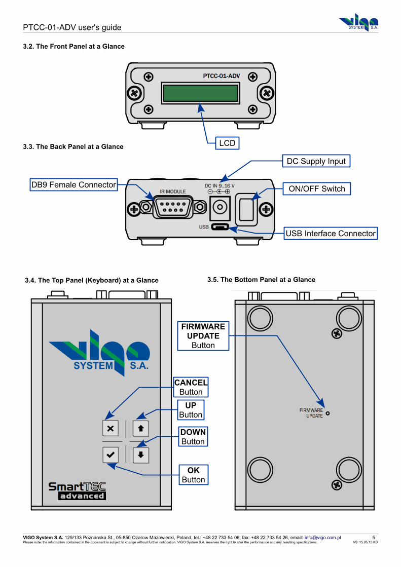
3.2. The Front Panel at a Glance
3.3. The Back Panel at a Glance
3.4. The Top Panel (Keyboard) at a Glance 3.5. The Bottom Panel at a Glance
VIGO System S.A. 129/133 Poznanska St., 05-850 Ozarow Mazowiecki, Poland, tel.: +48 22 733 54 06, fax: +48 22 733 54 26, email: [email protected] 5Please note: the information contained in the document is subject to change without further notification. VIGO System S.A. reserves the right to alter the performance and any resulting specifications. VS 15.05.15 KO
LCD
DC Supply Input
ON/OFF Switch
USB Interface Connector
DB9 Female Connector
UP Button
DOWN Button
CANCEL Button
OK Button
FIRMWAREUPDATE
Button

PTCC-01-ADV user's guide
4. PTCC-01-ADV Theory of Operation1. When the power supply is applied and IR detection KIT is turned on,PTCC probes the type of the connected IR detection module. WhenPIPDC or module containing internal 1-wire memory is found, thesettings are downloaded, and, following the user settings, thehardware is set. If the PTCC cannot find any of the said above moduletypes, and it is compatible with IR detection module with no memory,the PTCC internal settings are applied instead. If PTCC is notcompatible with “no memory” modules, it indicates an error andfinishes the operation.2. If no error occurs, the detector is then being cooled down. It usuallytakes around 30 seconds until the valid detector temperature isreached, the power supply for the IR module is being turned onafterwards, and the module is ready to operate.
3. The controller instantly probes the in-circuit currents and voltages. Ifany abnormal behavior is recognized (meaning short or open circuit onthe supply, TEC or thermistor lines, or the PTCC is unable to reach theset temperature of the detector within 2 minutes) the supply is beingturned off and the error is indicated.4. User can check the conditions of operation of the module and thecontroller using the user interface (the simplified keyboard and theLCD) or the PC and the software, which is available on the VIGOwebsite:http://www.vigo.com.pl/pub/File/download/SmartManager-setup.exe
5. PTCC-01-ADV Menu StructureThe menu is organized in three step circular menu. First step is main menu, second steps are submenus and third step is edition mode.
To move up or down in menuTo increase or decrease value of the parameter
To move left or right in menuTo choose the parameter to editTo cancel or accept
VIGO System S.A. 129/133 Poznanska St., 05-850 Ozarow Mazowiecki, Poland, tel.: +48 22 733 54 06, fax: +48 22 733 54 26, email: [email protected] 6Please note: the information contained in the document is subject to change without further notification. VIGO System S.A. reserves the right to alter the performance and any resulting specifications. VS 15.05.15 KO

PTCC-01-ADV user's guide
* available only when PIP module is connected.
VIGO System S.A. 129/133 Poznanska St., 05-850 Ozarow Mazowiecki, Poland, tel.: +48 22 733 54 06, fax: +48 22 733 54 26, email: [email protected] 7Please note: the information contained in the document is subject to change without further notification. VIGO System S.A. reserves the right to alter the performance and any resulting specifications. VS 15.05.15 KO

PTCC-01-ADV user's guide
6. Detailed Description of the Menu
6.1. Quick wiew of the most important parameters
TSET set temperature
TREAD read temperature
PWR preamplifier module power on/off
6.2. PTCC & IR module information
The information about PTTC, connected IR modul and IR detector.
6.2.1. PTCC serial number
6.2.2. IR module name
6.2.3. IR module serial number
VIGO System S.A. 129/133 Poznanska St., 05-850 Ozarow Mazowiecki, Poland, tel.: +48 22 733 54 06, fax: +48 22 733 54 26, email: [email protected] 8Please note: the information contained in the document is subject to change without further notification. VIGO System S.A. reserves the right to alter the performance and any resulting specifications. VS 15.05.15 KO

PTCC-01-ADV user's guide
6.2.4. Detector type
6.2.5. Detector serial number
6.3. PTCC Monitor
The PTCC parameters that are measured or read from the
memory.
6.3.1. Detector temperature
Detector temperature measured by PTTC-01-ADV.
6.3.2. TEC voltage
Thermoelectric cooler voltage measured by PTTC-01-ADV.
VIGO System S.A. 129/133 Poznanska St., 05-850 Ozarow Mazowiecki, Poland, tel.: +48 22 733 54 06, fax: +48 22 733 54 26, email: [email protected] 9Please note: the information contained in the document is subject to change without further notification. VIGO System S.A. reserves the right to alter the performance and any resulting specifications. VS 15.05.15 KO

PTCC-01-ADV user's guide
6.3.3. TEC current
Thermoelectric cooler current measured by PTTC-01-ADV.
6.3.4. SUPPLY+ current
Current consumption from the supply positive line.
6.3.5. SUPPLY- current
Current consumption from the supply negative line.
6.3.7. SUPPLY+ voltage
Positive supply line voltage.
VIGO System S.A. 129/133 Poznanska St., 05-850 Ozarow Mazowiecki, Poland, tel.: +48 22 733 54 06, fax: +48 22 733 54 26, email: [email protected] 10Please note: the information contained in the document is subject to change without further notification. VIGO System S.A. reserves the right to alter the performance and any resulting specifications. VS 15.05.15 KO

PTCC-01-ADV user's guide
6.3.8. SUPPLY- voltage
Negative supply line voltage.
6.3.9. Module type
N.C. - module not connected
No mem. - module with no configuration memory
1-wire - module with internal configuration memory
PIP Smart mod. - programmable intelligent IR module
IR detection module type.
6.3.10. PTCC status
"Temp.loopl ocked" STATUS - Detector temperature is equal(-/+ 1 K) to temperature defined by user.
"Cooling" STATUS - During the cooling proces.
"Not cooling" STATUS - The cooling is deactivated by user. Check PTTC settings.
"Det. Overheat" ERROR - The set temperature could not be reached during 120 second.
"Over current" ERROR - Measured current value is higher then maximum current value. Power is off.
"TEC open" ERROR - TEC circuit open connection.
"TEC short" ERROR - TEC circuit short connection.
"Therm.open" ERROR - Thermistor circuit open connection.
"Therm.short" ERROR - Thermistor circuit short connection.
"PTCC overheat" ERROR - The temperature inside PTCC is higher than limit.
"No module" ERROR - The connected modul without memory is not compatible or no module is connected.
"PIP data error" ERROR - PIP memory was detected but there are some comunication problem.
"1-wire error" ERROR - 1-wire memory was detected but there are some comunication problem.
"PTCC EEPR error" ERROR - Invalid values of parameters in configuration memory.
VIGO System S.A. 129/133 Poznanska St., 05-850 Ozarow Mazowiecki, Poland, tel.: +48 22 733 54 06, fax: +48 22 733 54 26, email: [email protected] 11Please note: the information contained in the document is subject to change without further notification. VIGO System S.A. reserves the right to alter the performance and any resulting specifications. VS 15.05.15 KO

PTCC-01-ADV user's guide
6.3.11. PTCC PWM output
hardware min.: 0
hardware max.: 65535
Peltier element is driven by PWM based output stage. Minimum PWM
value is 0 (meaning the TEC is not cooling) maximum is 65535 –
Peltier is driven with maximum power.
6.4. PTCC Settings
The PTCC parameters available for adjustment.
6.4.1. Supply control
AUTO the power supply for the module is turned on, when the valid
detector temperature is reached (default)
ON the power supply is always active
OFF the power supply is always inactive
The parameter controls the moment of turning the IR module supply
on to prevent powering the detector when not properly cooled down.
6.4.2. SUPPLY+ voltage
hardware min.: +3V
hardware max.: +15V
The following parameter establish the power supply value for the
positive supply line. Hardware limit is + 3 … + 15 V and may be limited
due to IR module safety.
VIGO System S.A. 129/133 Poznanska St., 05-850 Ozarow Mazowiecki, Poland, tel.: +48 22 733 54 06, fax: +48 22 733 54 26, email: [email protected] 12Please note: the information contained in the document is subject to change without further notification. VIGO System S.A. reserves the right to alter the performance and any resulting specifications. VS 15.05.15 KO

PTCC-01-ADV user's guide
6.4.3. SUPPLY- voltage
hardware min.: -3V
hardware max.: -15V
The following parameter establish the power supply value for the
negative supply line. Hardware limit is - 3 … - 15 V and may be limited
due to IR module safety.
6.4.4. FAN control
AUTO auxiliary voltage is enabled (default)
ON auxiliary voltage is enabled
OFF auxiliary voltage is inactive
Manipulating this parameter, user can enable or disable the auxiliary
+5 V supply used to power the cooling fan. When PIP-DC module is
connected, the parameter is inactive (because auxiliary voltage,
besides supplying the fan, is also used for supplying the
microcontroller and therefore needed for normal operation).
6.4.5. Detector temperature
In general, the parameter is responsible for the detector temperature
stabilized by the PTCC controller.
The lower temperature limit is due to the parameters of the Peltier
element. It doesn't make sense to set 100 K, if Peltier element may
achieve only 200 K. Establishing too low temperature is not risky,
however, the PTCC would in this case try to cool down the detector for
2 minutes and afterwards will indicate an error and stop working –
which may be confusing.
The upper limit is due to the detector safety reasons (for example, in
very rare cases, if detector is biased, the bias current may rise above
the safety margin in the room temperature and cause the detector
overheat, which the limit will prevent). The controller is unable to warm
up the detector, therefore there is no risk of heating up, instead of
cooling.
VIGO System S.A. 129/133 Poznanska St., 05-850 Ozarow Mazowiecki, Poland, tel.: +48 22 733 54 06, fax: +48 22 733 54 26, email: [email protected] 13Please note: the information contained in the document is subject to change without further notification. VIGO System S.A. reserves the right to alter the performance and any resulting specifications. VS 15.05.15 KO

PTCC-01-ADV user's guide
6.4.6. TEC maximum current
hardware min.: 0 A
hardware max.: 0.5 A
Defining the exact Peltier element parameters is not always needed for
the temperature control. However, depending on the Peltier element
type, there's always necessary to setup its maximum current.
6.5. PIP Monitor
Parameters measured internally by the PIP-DC.
Some of the options included in this sub-menu are redundant to the
options in PTCC monitor. Those repeated measurements help in
finding weak connection (for example: supply voltages measured by
PIPDC and PTCC may be compared to find weak connection).
The tolerable and measurable input voltage ranges are matched
individually for each monitor input to achieve proper dynamic range.
6.5.1. SUPPLY+ voltage
Positive supply line voltage.
6.5.2. SUPPLY- voltage
Negative supply line voltage.
VIGO System S.A. 129/133 Poznanska St., 05-850 Ozarow Mazowiecki, Poland, tel.: +48 22 733 54 06, fax: +48 22 733 54 26, email: [email protected] 14Please note: the information contained in the document is subject to change without further notification. VIGO System S.A. reserves the right to alter the performance and any resulting specifications. VS 15.05.15 KO
PTCC-01-ADV user's guide
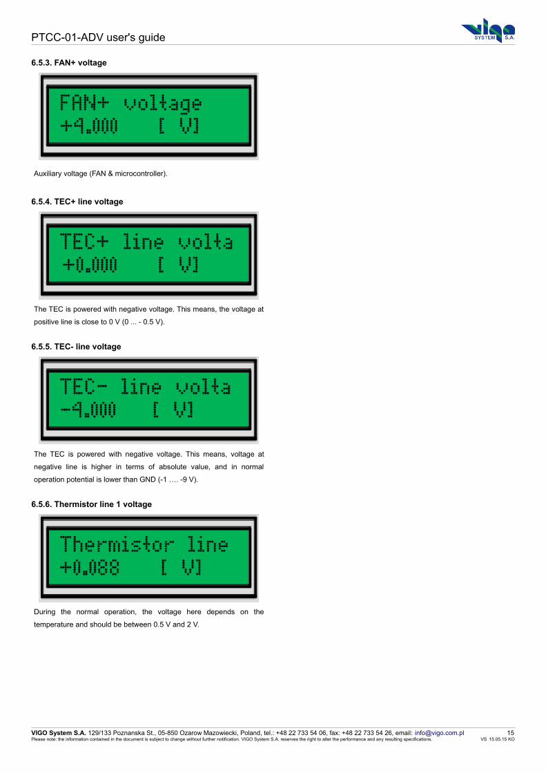
6.5.3. FAN+ voltage
Auxiliary voltage (FAN & microcontroller).
6.5.4. TEC+ line voltage
The TEC is powered with negative voltage. This means, the voltage at
positive line is close to 0 V (0 ... - 0.5 V).
6.5.5. TEC- line voltage
The TEC is powered with negative voltage. This means, voltage at
negative line is higher in terms of absolute value, and in normal
operation potential is lower than GND (-1 …. -9 V).
6.5.6. Thermistor line 1 voltage
During the normal operation, the voltage here depends on the
temperature and should be between 0.5 V and 2 V.
VIGO System S.A. 129/133 Poznanska St., 05-850 Ozarow Mazowiecki, Poland, tel.: +48 22 733 54 06, fax: +48 22 733 54 26, email: [email protected] 15Please note: the information contained in the document is subject to change without further notification. VIGO System S.A. reserves the right to alter the performance and any resulting specifications. VS 15.05.15 KO

PTCC-01-ADV user's guide
6.5.7. Thermistor line 2 voltage
This line is normally at ground potential. However, if the connection to
the PTCC is weak, the line is pulled up by the thermistor and line 1,
and the value is higher.
6.5.8. Detector bias voltage
This is the real measured voltage over the detector. This measurement
is particularly useful for checking the results of coarse adjustment the
detector bias voltage with the digital potentiometer.
6.5.9. 1st stage output voltage [DC monitor]
This measurement allows the user to check what is the DC IR
radiation level, even when AC coupling to the second stage is chosen.
This may be potentially useful in heterodyne detection.
By measuring the voltage at output of the 1st preamp stage, user can
check, whether is the risk of preamp saturation and what is the source
of output DC offset.
6.5.10. Output voltage
The output voltage measurement is useful especially, if it is not
possible to validate the setup connection with the oscilloscope. It is
also easy to perform an offset cancellation with no additional
equipment.
VIGO System S.A. 129/133 Poznanska St., 05-850 Ozarow Mazowiecki, Poland, tel.: +48 22 733 54 06, fax: +48 22 733 54 26, email: [email protected] 16Please note: the information contained in the document is subject to change without further notification. VIGO System S.A. reserves the right to alter the performance and any resulting specifications. VS 15.05.15 KO

PTCC-01-ADV user's guide
6.6. PIP advanced settings
User settings of the PIPDC module.
The current chapter contains the information regarding the PIP-DC
settings. As for the PTCC parameters, some of the parameter ranges
may be limited due to the detector and IR detection module safety
reasons.
6.6.1. Detector bias [0-256]
hardware min.: 0 0 V
hardware max.: 256 1 V
Vdet: bias voltage
The value set here directly drives internal digital potentiometer. The
dependence between the value and the bias voltage is linear.
6.6.2. Detector bias compensation [0-256]
hardware min.: 0 0 mA
hardware max.: 256 10 mA
U1st: the voltage behind the first stage
The value set here directly drives internal digital potentiometer. The
dependence between the value and the compensation current is linear.
The bias current compensation is used to avoid first preamplifier stage
saturation. It should be as close to zero volts as possible.
6.6.3. Preamp 2nd stage gain
The gain setting is responsible for the gain of the second stage.
Please note, than the full output voltage range is available, when the
gain is set between 5 V/V to 50 V/V.
Below 5 V/V, the output voltage range (+/- 1 V over 50 Ohm load) is
reduced. The dependence between the potentiometer setting and the
gain is linear in decibels.
VIGO System S.A. 129/133 Poznanska St., 05-850 Ozarow Mazowiecki, Poland, tel.: +48 22 733 54 06, fax: +48 22 733 54 26, email: [email protected] 17Please note: the information contained in the document is subject to change without further notification. VIGO System S.A. reserves the right to alter the performance and any resulting specifications. VS 15.05.15 KO

PTCC-01-ADV user's guide
6.6.4. Preamp output offset [0-256]
hardware min.: 0 ~ +1V
hardware max.: 256 ~ -1 V
Output voltage 0 V should appear at the output for the potentiometer
setting close to the half of the range (128).
When it is unable to achieve 0 V, first stage offset is too high, and
“Detector bias current compensation” must be adjusted to reduce it.
6.6.5. Preamp frequency compensation
hardware min.: 0 maximum parallel capacitance, lowest
top frequency
hardware max.: 4095 minumum parallel capacitance, highest
top frequency
The parameter changes the frequency compensation for the
preamplifier first stage. The lower value means the capacitance
parallel to the feedback resistor is relatively high, and therefore the
circuit might be over-compensated.
Higher value of the parameter gives weaker frequency compensation.
Lower values leads to oscillation, higher – the circuit is stable, however
the ringing behind the signal edges may be visible.
6.6.6. Preamp 1st stage transimpedance
LOW 1 kOhm
HIGH 5 kOhm
Higher transimpedance results in lower bandwidth (usually around
80 MHz, depending on detector type) and the frequency compensation
should be weaker. Preamp is normally more stable and less noisy
(5 pA /√Hz )
Lower transimpedance results in higher bandwidth (usually 220 MHz,
depending on the detector parameters), frequency compensation
should be stronger to avoid ringing. The input referred noise current
density is higher (8 pA /√Hz ).
Overall IR module transimpedance is calculated as a first stage
transimpedance times second stage gain. Therefore for 1 kOhm, the
transimpedance is 500 Ohm … 50 kOhm, and for 5 kOhm:
2.5 kOhm.... 250 kOhm.
The bandwidth doesn't depend on preamplifier second stage gain.
6.6.7. Coupling
AC
DC
VIGO System S.A. 129/133 Poznanska St., 05-850 Ozarow Mazowiecki, Poland, tel.: +48 22 733 54 06, fax: +48 22 733 54 26, email: [email protected] 18Please note: the information contained in the document is subject to change without further notification. VIGO System S.A. reserves the right to alter the performance and any resulting specifications. VS 15.05.15 KO

PTCC-01-ADV user's guide
AC coupling results in better output voltage stability, and in general,
full gain range is then available and output voltage offset correction is
simpler. The lower cut off frequency is around 1 kHz.
DC coupling allows the user to monitor the DC level IR radiation. The
IR detection module is less stable in terms of output DC offset, and
due to the instability, limited range of gain is convenient for usage.
6.6.8. Bandwidth
LOW 1.5 MHz
MEDIUM 15 MHz
FULL depends on detector parameters and first
stage transimpedance
It is possible to reduce the bandwidth down to 1.5 MHz or 15 MHz
compared to the full bandwidth, this reduces the output noise and
simplifies measurement when IR radiation level is weak.
6.6.9. Save user settings
User can store the PIP-DC settings in one of four memory banks.
When “Save user settings” is chosen, current configuration is saved.
6.6.10. Load user settings
User can load the PIP-DC settings from one of four memory banks.
Choosing “Load user settings” results in replacing current PIP-DC
settings with the settings from the bank.
When IR detection kit is restarted, last PIP-DC configuration is
restored.
VIGO System S.A. 129/133 Poznanska St., 05-850 Ozarow Mazowiecki, Poland, tel.: +48 22 733 54 06, fax: +48 22 733 54 26, email: [email protected] 19Please note: the information contained in the document is subject to change without further notification. VIGO System S.A. reserves the right to alter the performance and any resulting specifications. VS 15.05.15 KO

PTCC-01-ADV user's guide
6.7. Load defaults
All parameters which can be changed by user have default values.
This option is loading default parameters values from device memory.
7. Example - How to Move About Menu
In this example You can see how to change "Supply control" setup in PTTC settings.
The default screen that You see on PTTC display is "Quick view ofthe most important parameters".
To move to PTTC settings menu You need to click "down” button.
Now You can see first position of main menu "PTCC & IR moduleinformation".
Click "down” button.
You can see "PTCC Monitor".
Click "down” button.
VIGO System S.A. 129/133 Poznanska St., 05-850 Ozarow Mazowiecki, Poland, tel.: +48 22 733 54 06, fax: +48 22 733 54 26, email: [email protected] 20Please note: the information contained in the document is subject to change without further notification. VIGO System S.A. reserves the right to alter the performance and any resulting specifications. VS 15.05.15 KO

PTCC-01-ADV user's guide
You can see "PTTC settings".
Click " OK button" to enter to the "PTTC settings" menu.
You can see "Supply control" submenu. As You can see Supplycontrol is in AUTO mode.In this example We want to change AUTO mode to ON mode.
Click "OK” button to go to the edition mode.
In the edit mode a fourth position in the second line is underscore andis blinking.
The AUTO mode is last position from this menu so "down” button isuseless.Click "up” button to change supply control mode to ON.
Click "OK” button to accept changes and exit from edition mode.
or click "Cancel" button co cancel changes and exit from edition mode.
VIGO System S.A. 129/133 Poznanska St., 05-850 Ozarow Mazowiecki, Poland, tel.: +48 22 733 54 06, fax: +48 22 733 54 26, email: [email protected] 21Please note: the information contained in the document is subject to change without further notification. VIGO System S.A. reserves the right to alter the performance and any resulting specifications. VS 15.05.15 KO

PTCC-01-ADV user's guide
8. PC Software Description "Smart Manager"
8.1. Program Description
Smart Manager is easy to use tool to control PTTC controller. The PC software is showing all PTTC-01-ADV menus in one window.
1. PTCC version & serial number2. Storing/loading PTCC & IR detection module configuration data3. PTCC settings4. PTCC monitor5. IR detection module & detector parameters6. IR detection module settings (available only for PIP) 7. IR detection module (available only for PIP)8. Automatic PTCC/PIP monitor update
Usually, user settings are available for the adjustment within factorylimits (narrower than the hardware limits). For example, if the IRmodule power supply is +/- 9 V, then allowing the user to manipulatethe supply voltage with no limits is considered as a potential source ofthe module damage. The limits are applied in the factory and user isunable to adjust the values in full range.
In the PC software, there is a green part of the slider showing theparameter range available for the user, or the buttons are clickable.Unavailable buttons are grayed instead.
Unavailable buttons are grayed instead.
VIGO System S.A. 129/133 Poznanska St., 05-850 Ozarow Mazowiecki, Poland, tel.: +48 22 733 54 06, fax: +48 22 733 54 26, email: [email protected] 22Please note: the information contained in the document is subject to change without further notification. VIGO System S.A. reserves the right to alter the performance and any resulting specifications. VS 15.05.15 KO

PTCC-01-ADV user's guide
8.2. Smart Manager First Use
To start using the Smart Manager connect PTTC module to USB port in Your PC and open the Smart Manager.
You can see a device list if the list is empty check USB connection and reload device list.Devices >> Reload Devices ListChose the devices that You want to control and click two times on chosen element.
VIGO System S.A. 129/133 Poznanska St., 05-850 Ozarow Mazowiecki, Poland, tel.: +48 22 733 54 06, fax: +48 22 733 54 26, email: [email protected] 23Please note: the information contained in the document is subject to change without further notification. VIGO System S.A. reserves the right to alter the performance and any resulting specifications. VS 15.05.15 KO

PTCC-01-ADV user's guide
8.3. Update Procedure
Smart Manager automatically check if any updates to PTTC software are available. If software to update is available Smart Manager sendcommunicate to user.
When user allow to update Smart Manager start update procedure.
User have to follow Instruction showed in Firmware Upgrade window.
VIGO System S.A. 129/133 Poznanska St., 05-850 Ozarow Mazowiecki, Poland, tel.: +48 22 733 54 06, fax: +48 22 733 54 26, email: [email protected] 24Please note: the information contained in the document is subject to change without further notification. VIGO System S.A. reserves the right to alter the performance and any resulting specifications. VS 15.05.15 KO

PTCC-01-ADV user's guide
9. Safety InstructionsTo ensure safe and failure-free operation of the SmartTEC controller, comply with the following precautions:
Before connecting the power supply to the mains, make sureit is compatible with the mains voltage and frequency.
Use the cables delivered by VIGO. In case of OEM systems,make sure the cables match the specification of the controller.
The power supply is intended for the indoor use.Turn off the power supply before plugging/unplugging cables.Avoid static discharges.
Do not use the controller if the temperature and the air humidityextends the values valid for the PTCC-01-ADV controller.
Use the proper cables to connect elements of the kit, dedicatedfor specified device only. Never cut or shorten any cable, it maycause damage to your device.
VIGO System S.A. 129/133 Poznanska St., 05-850 Ozarow Mazowiecki, Poland, tel.: +48 22 733 54 06, fax: +48 22 733 54 26, email: [email protected] 25Please note: the information contained in the document is subject to change without further notification. VIGO System S.A. reserves the right to alter the performance and any resulting specifications. VS 15.05.15 KO