PRELIMINARY NUMERICAL AND EXPERIMENTAL ... NUMERICAL AND EXPERIMENTAL ANALYSIS OF THE SPALLATION...
7
PRELIMINARY NUMERICAL AND EXPERIMENTAL ANALYSIS OF THE SPALLATION PHENOMENON Alexandre Martin *1 , Sean C.C. Bailey †1 , Francesco Panerai ‡1,2 , Raghava S.C. Davuluri §1 , Alexander R. Vazsonyi ¶1 , Huaibao Zhang §1 , Zachary S. Lippay ¶1 , Nagi N. Mansour k2 , Jennifer A. Inman **3 , Brett F. Bathel **3 , Scott C. Splinter ††3 , and Paul M. Danehy **3 1 University of Kentucky, Lexington, KY 40506 2 NASA Ames Research Center, Moffett Field, CA, 94035 3 NASA Langley Research Center, Hampton, VA, 23681 ABSTRACT The spallation phenomenon was studied through numer- ical analysis using a coupled Lagrangian particle track- ing code and a hypersonic aerothermodynamics compu- tational fluid dynamics solver. The results show that car- bon emission from spalled particles results in a signif- icant modification of the gas composition of the post- shock layer. Preliminary results from a test-campaign at the NASA Langley HYMETS facility are presented. Us- ing an automated image processing of high-speed images, two-dimensional velocity vectors of the spalled particles were calculated. In a 30 second test at 100 W/cm 2 of cold-wall heat-flux, more than 1300 particles were de- tected, with an average velocity of 102 m/s, and most fre- quent observed velocity of 60 m/s. Key words: ablation; spallation; arc-jet; thermal protec- tion system. 1. INTRODUCTION Low density ablators are one of the preferred class of material for protecting space vehicles during atmospheric entry. Through various physical processes [7, 14] such as near-surface oxidation, pyrolysis chemical reaction, va- porization, and other decomposition processes, these ma- terials reduce the amount of heat being conducted to the surface of the vehicle. These beneficial processes usu- ally fall under the umbrella term “ablation”. The spal- lation phenomenon [6, 11] also belongs in this category; however, unlike the other processes involved in ablation, spallation is generally regarded as undesirable. * Assistant Professor, Department of Mechanical Engineering, [email protected] † Assistant Professor, Department of Mechanical Engineering ‡ Research Fellow, Department of Mechanical Engineering, NASA Visiting Scientist, Thermal Protection, Materials Branch § Graduate Student, Department of Mechanical Engineering ¶ Student, Department of Mechanical Engineering k Chief Scientist, Advanced Supercomputing Division ** Research Scientist, Advanced Measurements and Data Systems Branch †† Aerospace Engineer, Structural Mechanics and Concepts Branch Spallation is typically described as the ejection of solid particles off the surface of the material. Those parti- cle are then convected away in the flow field. The ex- act cause of this phenomenon is unclear, although it is likely to be caused by mechanical erosion of the fibrous surface, and weakened by oxidative decomposition, com- bined with the shear stresses introduced by the fluid flow. Soot formation from the pyrolysis gas is also a potential cause of spalled particles. The aerodynamic heating rates of re-entry vehicles may be affected by spallation through various mechanisms. For instance, the solid particles ejected from the surface can modify the near surface chemical processes and flow field. Mechanical erosion can lead to an irregular surface, and in turn, to an augmented surface roughness. Such a modification of the surface, as well as the presence of par- ticles in the boundary layer, could potentially trigger tran- sition from laminar to turbulent flow. Finally, mechan- ical erosion results in an accelerated surface recession, thereby reducing the effectiveness of the thermal protec- tion system (TPS). Material response codes, such as the ones used by NASA to design TPS, take into account this accelerated failure mechanism through introduction of an empirically calculated parameter [8]. Therefore, there is a need to better understand and model the spallation phe- nomenon, including its source and impact on TPS perfor- mance. To further investigate spallation effects, a Lagrangian par- ticle tracking code was developed. This code computes the dynamics of spalled particles as they travel through a flow field. The code uses a finite-rate chemistry model to predict the chemical interactions of the particles with the flow field. This particle tracking code can then be dynam- ically coupled to a computational fluid dynamics (CFD) solver which models the time-accurate hypersonic flow field around ablative samples. A preliminary analysis performed using this coupled approach is presented here. To support the spallation modeling effort, an experi- mental investigation was performed at the NASA Lan- gley Hypersonic Materials Environmental Test System (HYMETS) facility [4]. HYMETS is a 400 kW arcjet https://ntrs.nasa.gov/search.jsp?R=20150013986 2018-06-17T08:11:05+00:00Z
Transcript of PRELIMINARY NUMERICAL AND EXPERIMENTAL ... NUMERICAL AND EXPERIMENTAL ANALYSIS OF THE SPALLATION...

PRELIMINARY NUMERICAL AND EXPERIMENTAL ANALYSIS OF THE SPALLATIONPHENOMENON
Alexandre Martin∗1, Sean C.C. Bailey†1, Francesco Panerai‡1,2, Raghava S.C. Davuluri§1,Alexander R. Vazsonyi¶1, Huaibao Zhang§1, Zachary S. Lippay¶1, Nagi N. Mansour‖2, Jennifer A. Inman∗∗3,
Brett F. Bathel∗∗3, Scott C. Splinter††3, and Paul M. Danehy∗∗3
1University of Kentucky, Lexington, KY 405062NASA Ames Research Center, Moffett Field, CA, 940353NASA Langley Research Center, Hampton, VA, 23681
ABSTRACT
The spallation phenomenon was studied through numer-ical analysis using a coupled Lagrangian particle track-ing code and a hypersonic aerothermodynamics compu-tational fluid dynamics solver. The results show that car-bon emission from spalled particles results in a signif-icant modification of the gas composition of the post-shock layer. Preliminary results from a test-campaign atthe NASA Langley HYMETS facility are presented. Us-ing an automated image processing of high-speed images,two-dimensional velocity vectors of the spalled particleswere calculated. In a 30 second test at 100 W/cm2 ofcold-wall heat-flux, more than 1300 particles were de-tected, with an average velocity of 102 m/s, and most fre-quent observed velocity of 60 m/s.
Key words: ablation; spallation; arc-jet; thermal protec-tion system.
1. INTRODUCTION
Low density ablators are one of the preferred class ofmaterial for protecting space vehicles during atmosphericentry. Through various physical processes [7, 14] such asnear-surface oxidation, pyrolysis chemical reaction, va-porization, and other decomposition processes, these ma-terials reduce the amount of heat being conducted to thesurface of the vehicle. These beneficial processes usu-ally fall under the umbrella term “ablation”. The spal-lation phenomenon [6, 11] also belongs in this category;however, unlike the other processes involved in ablation,spallation is generally regarded as undesirable.∗Assistant Professor, Department of Mechanical Engineering,
[email protected]†Assistant Professor, Department of Mechanical Engineering‡Research Fellow, Department of Mechanical Engineering, NASA
Visiting Scientist, Thermal Protection, Materials Branch§Graduate Student, Department of Mechanical Engineering¶Student, Department of Mechanical Engineering‖Chief Scientist, Advanced Supercomputing Division∗∗Research Scientist, Advanced Measurements and Data Systems
Branch††Aerospace Engineer, Structural Mechanics and Concepts Branch
Spallation is typically described as the ejection of solidparticles off the surface of the material. Those parti-cle are then convected away in the flow field. The ex-act cause of this phenomenon is unclear, although it islikely to be caused by mechanical erosion of the fibroussurface, and weakened by oxidative decomposition, com-bined with the shear stresses introduced by the fluid flow.Soot formation from the pyrolysis gas is also a potentialcause of spalled particles.
The aerodynamic heating rates of re-entry vehicles maybe affected by spallation through various mechanisms.For instance, the solid particles ejected from the surfacecan modify the near surface chemical processes and flowfield. Mechanical erosion can lead to an irregular surface,and in turn, to an augmented surface roughness. Such amodification of the surface, as well as the presence of par-ticles in the boundary layer, could potentially trigger tran-sition from laminar to turbulent flow. Finally, mechan-ical erosion results in an accelerated surface recession,thereby reducing the effectiveness of the thermal protec-tion system (TPS). Material response codes, such as theones used by NASA to design TPS, take into account thisaccelerated failure mechanism through introduction of anempirically calculated parameter [8]. Therefore, there isa need to better understand and model the spallation phe-nomenon, including its source and impact on TPS perfor-mance.
To further investigate spallation effects, a Lagrangian par-ticle tracking code was developed. This code computesthe dynamics of spalled particles as they travel through aflow field. The code uses a finite-rate chemistry model topredict the chemical interactions of the particles with theflow field. This particle tracking code can then be dynam-ically coupled to a computational fluid dynamics (CFD)solver which models the time-accurate hypersonic flowfield around ablative samples. A preliminary analysisperformed using this coupled approach is presented here.
To support the spallation modeling effort, an experi-mental investigation was performed at the NASA Lan-gley Hypersonic Materials Environmental Test System(HYMETS) facility [4]. HYMETS is a 400 kW arcjet
https://ntrs.nasa.gov/search.jsp?R=20150013986 2018-06-17T08:11:05+00:00Z

that can simulate hypersonic flight and Earth or Martianentry conditions. High speed imagery was used to capturespalled particles ejecting from FiberForm R©, and PICAtest samples at target heat flux conditions of 100, 200, and400 W/cm2. From this data, measurements of particle ve-locity and trajectory were obtained. An initial assessmentof the data for one FiberForm R© sample is presented here.
2. NUMERICAL SIMULATIONS
2.1. Numerical models
The flow field solutions used to predict the trajectoriesof spalled particles following ejection from the surfacewere obtained using the hypersonic CFD code KATS– Kentucky Aerothermodynamics and Thermal-responseSolver [16, 17]. KATS is a three-dimensional laminarNavier-Stokes solver that computes flow fields in thermo-chemical non-equilibrium in the continuum regime. Thetranslational and rotational energy modes of the speciesof the gas are described by a single temperature Ttr, whilethe vibrational and electronic energy modes, as well aselectron translational energy mode, are characterized byanother single temperature Tve. The individual speciesviscosity model used to compute the diffusive fluxes wasobtained using the Blottner curve fits [1]. Euken’s rela-tions [13] were used to account for species thermal con-ductivity. The mixture transport properties are approx-imated using Wilke’s semi-empirical mixing rule. Forreacting flows, a standard finite-rate chemical kineticsmodel was used.
The spallation code used for this preliminary analysismodels the dynamics of individual particles ejected fromthe surface of a test articles, using a steady-state flow-field solution as an initial condition. The code uses theflow field information to determine the trajectory of theparticle. The following assumptions are used to derivethe governing equations:
1. The spalled particles are spherical2. The spalled particles are made of graphite3. Heat and mass transfer rates are uniform over the
surface of the particle4. Thermophysical properties of the particle are as-
sumed to be uniform over the entire particle
Graphite is chosen since charred PICA is considered to becarbon, and that thermochemical properties of graphiteare available in the literature. A Lagrangian formulationis employed to compute the projected path of the spalledparticle. The corresponding governing equations are
∂
∂t
(mp
mpup
mpEp
)=
(−mC/CO − mC/CN − mC/sub
FD
qconv + pdrag − qrad + qrxn
).
(1)
In the left hand side, mp, up and Ep are respectively themass, the velocity vector and the energy of the spalledparticle. In the right hand side, FD, qconv , pdrag, qrad
Table 1. Surface chemistry model used to calculate theerosion of the spalled particles in the flow field
Reactions TypeC(s) + O −−→ CO Oxidation
2 C(s) + O2 −−→ 2 CO OxidationC(s) + N −−→ CN Nitridation
C(s) −−→ C Sublimation2 C(s) −−→ C2 Sublimation3 C(s) −−→ C3 Sublimation
Table 2. Free stream and wall properties of the Mach 5argon flow
ρ∞ U∞ Ttr Tve Tw[kg/m3] [m/s] [K] [K] [K]
3.45× 10⁻³ 3860 1470 1470 500
and qrxn are, respectively, the drag force, the convectiveheating, the power loss caused by drag, the re-radiativeheating and the chemical energy term.
As they travel in the flow field, the particles chemicallyreact with the flow. As the particles lose mass, their radiusis reduced. The gas/particle interaction is modeled usinga finite-rate rate chemistry model that accounts for threetypes of non-homogeneous reactions: oxidation, nitrida-tion, and sublimation [3]. The three types are respectivelyrepresented in Eq. 1 by the mass source terms mC/CO,mC/CN and mC/sub. The complete reaction mechanismis provided in Table 1.
This spallation model and coupling strategy has been ex-tensively verified; more details are given in Ref. [3]
2.2. Preliminary results
The test case considered here consists of a Mach 5 highenthalpy flow over an axi-symmetric solid sample with aradius of 3.30 cm, and an axial length of 0.82 cm. Thesetest conditions are representative of what is observed inthe HYMETS facility [2, 4].
First, a parametric study was performed to evaluate theeffects of the ejection conditions (ejection velocity, parti-cle size and ejection angle) on the trajectory of the parti-cle [3]. For the flow field, a Mach 5 argon flow was used,with flow conditions listed in Table 2. In the table, Twrefers to the temperature at the surface of the sample. Ar-gon was chosen as it simplifies the flow field solution, andallow the particle to travel the flow field without reacting.As can be seen in Fig. 1(a) to Fig. 1(c), changing the ejec-tion conditions considerably changes the trajectory of theparticle. Therefore, if trajectories are measured experi-mentally, they could provide valuable insights about theejection conditions.
Next, to allow evaluation of the effects of a spalled par-ticle interacting with a flow field upstream of a test arti-

(a) Particle radius variation (vp = 25m/s, θ = 0◦)
(b) Angle variation (mp = 10 μm, vp =100 m/s )
(c) Ejection velocity variation(mp = 50 μm, θ = 0◦)
Figure 1. Particle trajectories as a result of the study for the ejection parameters of spalled particle in a Mach 5 argonflow
cle, the spallation code was coupled with KATS. Using atime-accurate simulation, the carbon species emitted bythe spalled particle traveling in the flow field was trans-ferred to the CFD code through mass source terms. Forthis specific case, a Mach 5 air flow field is used, withconditions listed in Table 3. In this table, Yi representsthe mass faction of individual species i. For this simula-tion, a 30 micron carbon particle was ejected normal tothe surface, 5 mm from the stagnation point, at a veloc-ity of 90 m/s. The simulation takes place over a physicaltime of 0.7 ms, and the results are presented in Fig. 2.In Fig. 2(a), the entire trajectory of the particle is seenover the temperature field. It can be seen in Fig. 2(b) toFig. 2(d) that the particle ejects a significant amount ofcarbon species, and that this carbon diffuses around theparticles in all directions before being convected away. Itis clear from this preliminary analysis that these carbonspecies would react with the incoming flow, and that ad-ditional species such as CN could be created. These ob-servations reinforce the hypothesis that spalled particlescould be responsible for a previously unexplained strongspectroscopic signature observed in some arc-jet test dataupstream of the sample [5, 9, 10, 15].
3. EXPERIMENT
3.1. Facility and instrumentation
A series of preliminary test was performed at theHYMETS facility at the NASA Langley Research Cen-ter to assess the feasibility of identifying and trackingspalled particles ejected from TPS materials. As opposedto large-scale arc-jet wind tunnels, HYMETS can be op-erated by a minimal staff, can be run for a long period,and has essentially no downtime between runs. Hence,
it is ideal for exploratory studies such as those of thepresent research effort. Moreover, the facility is equippedwith numerous optical ports which allow the possibilityof complex diagnostics and image capturing [4].
As previously noted, the purpose of the present test-campaign was to confirm the presence of spalled particlesfor different test articles throughout a range of flow con-ditions. During these tests, the facility was equipped withthe following:
• four high speed cameras for particle detection at dif-ferent view angles, two of them linked for stereo-scopic measurements• two spectrometers (VUV and N-IR)• an infrared camera• a two color single-point pyrometer for surface tem-
perature measurements• three intrusive probes for flow calibration• three thermocouples at the back face of each sample
A total of ten samples of PICA [12] and FiberForm R©
were tested in air plasma, under three cold-wall heat fluxconditions (100, 200 and 400 W/cm2). All samples hada diameter of 3.30 cm, and a height of 2.54 cm, whichincluded a 0.38 cm Li-2200 collar for some samples. Inaddition, three graphite, and three Li-2200 samples weretested under the same heat fluxes. The following sec-tion present preliminary measurements on spalling par-ticle with high speed imaging, leaving a thorough doc-umentation of the test campaign measurements to futurepublications.
Fig. 3 is a composite image compiled from all frames dur-ing a 30 s test of FiberForm R© at 100 W/cm2. The images

Table 3. Free stream temperature and wall properties of the Mach 5 air flowρ∞ U∞ Ttr Tve Tw YAr YN2
YO2YNO YN YO
[kg/m3] [m/s] [K] [K] [K]1.46× 10⁻³ 3163 896 896 600 0.0704 0.7178 0.0613 0.0469 0.0000 0.1036
(a) Trajectory and temperaturefield
(b) Carbon density, t =0.17ms
(c) Carbon density, t =0.35ms
(d) Carbon density, t =0.53ms
Figure 2. Temperature field, trajectory and density of the carbon species emitted from a 30 micron spalled particle ejectedat 90 m/s in a Mach 5 air flow.
used to construct this figure were obtained using a 12-bitmonochrome pco.dimax HD high-speed CMOS camera,cropped down to 672×608 pixels from the 1920×1080full sensor array in order to reduce file size. As canbe seen, numerous spalled particles are observed beingejected from the samples. The same observation wasmade at flows with lower cold-wall heat flux conditions.Spallation was systematically observed during all tests ofFiberForm R© and PICA samples. The graphite and Li-2200 samples however, showed no evidence of spallation.
3.2. Particle tracking
To provide a quantitative evaluation of the spalled parti-cle behavior, data was analyzed from an IDT MotionXtraN-4S1, 1016×1016, 10-bit mono camera located orthog-onally to the sample. The test case presented here is for aFiberForm R© sample subjected to a 200 W/cm2 heat fluxfor 30 s. The camera was set to double-exposure modewith the first exposure of 30 μs, followed 100 ns later bya second exposure of approximately 470 μs. Due to lim-itations in the on-board memory of the camera, both ex-posures were acquired at a sampling frequency of only 15Hz. This ensured that images were acquired for the entireduration of the 30 s placement of the sample within thearc-jet. As a result, 946 images were acquired over 31.5s, with 473 images acquired at each exposure duration.
Figure 3. Integrated image of a FiberForm R© samplessubjected to a 400 W/cm2 heat flux. The image is a re-construction formed by combining the brightest pixel ofapproximately 900 images taken during a 30-second ex-periment. These images were acquired at a frame rate of30 Hz with an exposure time of 25 µs
It should be note that only the first exposure was ana-lyzed, with analysis of the second exposure left for futurework. A single, unprocessed image is shown in Fig. 4(a).A small particle trace can be seen in the top of the im-
(a) Original image (b) Enhanced image (c) Processed image
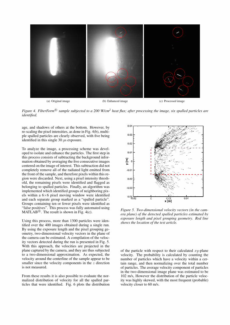
Figure 4. FiberForm R© sample subjected to a 200 W/cm2 heat flux; after processing the image, six spalled particles areidentified.
age, and shadows of others at the bottom. However, byre-scaling the pixel intensities, as done in Fig. 4(b), multi-ple spalled particles are clearly observed, with five beingidentified in this single 30 μs exposure.
To analyze the image, a processing scheme was devel-oped to isolate and enhance the particles. The first step inthis process consists of subtracting the background infor-mation obtained by averaging the five consecutive imagescentered on the image of interest. This subtraction did notcompletely remove all of the radiated light emitted fromthe front of the sample, and therefore pixels within this re-gion were discarded. Next, using a pixel intensity thresh-old, the remaining pixels were identified and flagged asbelonging to spalled particles. Finally, an algorithm wasimplemented which identified groups of neighboring pix-els within a 6×6 pixel moving window were identifiedand each separate group marked as a “spalled particle”.Groups containing ten or fewer pixels were identified as“false positives”. This process was fully automated usingMATLAB R©. The result is shown in Fig. 4(c).
Using this process, more than 1300 particles were iden-tified over the 400 images obtained during a single run.By using the exposure length and the pixel grouping ge-ometry, two-dimensional velocity vectors in the plane ofthe camera can be estimated. A compilation of the veloc-ity vectors detected during the run is presented in Fig. 5.With this approach, the velocities are projected in theplane captured by the camera, and they are thus subjectedto a two-dimensional approximation. As expected, thevelocity around the centerline of the sample appear to besmaller since the velocity components in the z directionis not measured.
From these results it is also possible to evaluate the nor-malized distribution of velocity for all the spalled par-ticles that were identified. Fig. 6 plots the distribution
Figure 5. Two-dimensional velocity vectors (in the cam-era plane) of the detected spalled particles estimated byexposure length and pixel grouping geometry. Red lineshows the location of the test article.
of the particle with respect to their calculated xy-planevelocity. The probability is calculated by counting thenumber of particles which have a velocity within a cer-tain range, and then normalizing over the total numberof particles. The average velocity component of particlesin the two-dimensional image plane was estimated to be102 m/s, However the distribution of the particle veloc-ity was highly skewed, with the most frequent (probable)velocity closer to 60 m/s.

Figure 6. Magnitude of the velocity distribution of the de-tected spalled particles. The magnitude is only calculatedusing two measured components, in the camera plane.
4. CONCLUSION AND OUTLOOK
This paper presents the recent advances in research re-lated to the ablative phenomenon – spallation. To inves-tigate the effects of spallation on the flow field, a nu-merical code was developed. The results showed that aspalled particle ejected in a reacting flow would releasecarbon species in the flow field. This carbon is in suf-ficient quantity that it is likely to form CN species, andtherefore explain the CN emission detected by spectro-scopic experiments.
High speed imaging measurements allowed observationof multiple spalled particles during an arc-jet test run onPICA and FiberForm R© samples. An automated imageanalysis procedure allowed detection of as many as 1300single particles being ejected from the surface during a30 s test run.
These results, although still preliminary, are very encour-aging. Particle tracking based on stereoscopic imagingwill enable improvements in the determination of par-ticle velocities and trajectories in the three-dimensionalspace. Using the numerical method combined with theimages obtained during the test campaign, it will be pos-sible to gather more information about the trajectory andinitial state of the spalled particles. This will undoubtedlylead to a better understanding on how these particles areformed, and what process is responsible for their high-speed ejection.
ACKNOWLEDGMENTS
Financial support for this work was provided by NASAKentucky EPSCoR Award NNX10AV39A and NASAAward NNX13AN04A. Additional support was gener-ously provided by the Hypersonic EDL program, throughM.J. Wright at NASA Ames. The authors are immenselygrateful to him. They also would like to thank M.J. Gaschat NASA Ames, and J.G. Gragg and S.B. Jones at NASALangley for their technical assistance. Lastly, the authorare grateful to K.A. Tagavi for carefully reviewing the
manuscript, as well as E. Sozer at NASA Ames ResearchCenter for numerous insightful discussions on the CFDcode.
REFERENCES
[1] Blottner, F. G., Johnson, M., & Ellis, M. 1971,Chemically reacting viscous flow program formulti-component gas mixtures., Tech. Rep. SC-RR-70-754, Sandia National Laboratories, Albu-querque, New Mexico
[2] Danehy, P. M., Hires, D. V., Johansen, C. T., Bathel,B. F., Jones, S. B., Gragg, J. G., Splinter, S. C. 2012,in 50th AIAA Aerospace Sciences Meeting and Ex-hibit, AIAA Paper 2012-856, Nashville, TN
[3] Davuluri, R. S. C., Zhang, H., & Martin, A. 2015,Journal of Thermophysics and Heat Transfer, 29
[4] Inman, J. A., Bathel, B. F., Johansen, C. T., Danehy,P. M., Jones, S. B., Gragg, J. G., Splinter, S. C.2013, AIAA Journal, 51, 2365
[5] Kihara, H., Hatano, M., Nakiyama, N., Abe, K., &Nishida, M. 2006, Transactions of the Japan Societyfor Aeronautical and Space Sciences, 49, 65
[6] Lundell, J. H. 1982, in AIAA/ASME 3rd Joint Ther-mophysics and Heat Transfer Conference, AIAAPaper 82-0852, St. Louis, MO
[7] Martin, A. & Boyd, I. D. 2015, Journal of Thermo-physics and Heat Transfer, 29, in Press
[8] Milos, F. & Chen, Y.-K. 2010, in 10th AIAA/ASMEJoint Thermophysics and Heat Transfer Confer-ence, AIAA Paper 2010-4663, Chicago, IL
[9] Park, C., Raiche, G. A., & Driver, D. M. 2004, Jour-nal of Thermophysics and Heat Transfer, 18, 519
[10] Raiche, G. A. & Driver, D. M. 2004, in 42th AIAAAerospace Sciences Meeting and Exhibit, AIAAPaper 2004-0825, Reno NV
[11] Sullivan, J. M. & Kobayashi, W. S. 1987, in 22ndAIAA Thermophysics Conference, AIAA Paper1987-1516, 1–7
[12] Tran, H. K., Johnson, C. E., Rasky, D. J., Hui,F. C. L., Hsu, M.-T., Chen, Y. K. 1996, in 31stAIAA Thermophysics Conference, AIAA Paper1996-1911, New Orleans, LA, 1–14
[13] Vincenti, W. G. & Kruger, C. H. 1982, Introduc-tion to Physical Gas Dynamics (Krieger PublishingCompany)
[14] Weng, H., Bailey, S. C. C., & Martin, A. 2015, In-ternational Journal of Heat and Mass Transfer, 80,570
[15] Yoshinaka, T. 1998, Spallation Measurement at theAblator Plasma Wind Tunnel Tests, Tech. Rep.NASDA-TMR-970006E, National Space Develop-ment Agency of Japan, Tokyo
[16] Zhang, H., Martin, A., & McDonough, J. M. 2012,in 24th International Conference on Parallel Com-putational Fluid Dynamics, Atlanta, GA

[17] Zhang, H., Weng, H., & Martin, A. 2014, in 52ndAIAA Aerospace Sciences Meeting, AIAA Paper2014-1209, National Harbor, MD