EXPERIMENTAL AND NUMERICAL INVESTIGATION OF … · The compact heat exchangers are ... carried out...
14
Karthik, P.,, et al.: Experimental and Numerical Investigation of a … THERMAL SCIENCE, Year 2015, Vol. 19, No. 2, pp. 679-692 679 EXPERIMENTAL AND NUMERICAL INVESTIGATION OF A LOUVERED FIN AND ELLIPTICAL TUBE COMPACT HEAT EXCHANGER by Pooranachandran KARTHIK a , Sheik Ismail LIAGUAT ALI KHAN b , Kulasekharan NARASINGAMURTHI c , and Velraj RAMALINGAM b* a Department of Mechanical Engineering, RMD Engineering College, Thiruvalluvar, Tamil Nadu, India b Aeronautical Development and Agency, Bangalore, Karnataka, India c GE India, Bangalore, Karnataka, India d Institute for Energy Studies, Anna University, Chennai, India Original scientific paper DOI: 10.2298/TSCI120220146P In the present work, an experimental investigation is carried out to analyze the heat transfer characteristics of a louvered fin and elliptical tube compact heat exchanger used as a radiator in an internal combustion engine. Experiments are conducted by positioning the radiator in an open-loop wind tunnel. A total of 24 sets of air, water flow rate combinations are tested, and the temperature drops of air and water were acquired. A numerical analysis has been carried out using Fluent software (a general purpose computational fluid dynamics simulation tool) for three chosen data from the experiments. The numerical air-side temper- ature drop is compared with those of the experimental values. A good agreement between the experimental and numerical results validates the present computa- tional methodology. Key words: louvered fin, compact heat exchanger, computational fluid dynamics, Fluent Introduction The fin and tube heat exchanger is a form of compact heat exchanger which consists of alternate layers of fin and tubes. According to the flow arrangements, compact heat ex- changers are classified as single-pass cross flow, counter flow, and multi-pass cross-counter flow. The last two flow arrangements can yield streams and very small pressure drops com- pared to shell and tube heat exchangers. The compact heat exchangers are widely used in au- tomobiles, power plants, natural gas processing, space heating, refrigeration, air conditioning, etc. Depending on the application, various fin patterns such as plate, louver, convex-louver and wavy are used in the fin side (air side). They have a high degree of surface compactness and substantial heat transfer enhancement, obtained as a result of the periodic starting and devel- opment of the laminar boundary layers, over interrupted channels formed by the fins and their dissipation in the fin wakes. There is, of course, an associated increase in the pressure drop due to increased friction and form drag contribution from the finite thickness of the interrupted fins. The typical tube geometries used in these heat exchangers are circular and elliptical. –––––––––––––– * Corresponding author; e-mail: [email protected]
Transcript of EXPERIMENTAL AND NUMERICAL INVESTIGATION OF … · The compact heat exchangers are ... carried out...

Karthik, P.,, et al.: Experimental and Numerical Investigation of a … THERMAL SCIENCE, Year 2015, Vol. 19, No. 2, pp. 679-692 679
EXPERIMENTAL AND NUMERICAL INVESTIGATION OF A LOUVERED FIN AND ELLIPTICAL TUBE
COMPACT HEAT EXCHANGER
by
Pooranachandran KARTHIK a, Sheik Ismail LIAGUAT ALI KHAN
b,
Kulasekharan NARASINGAMURTHI c, and Velraj RAMALINGAM
b* a Department of Mechanical Engineering, RMD Engineering College, Thiruvalluvar, Tamil Nadu, India
b Aeronautical Development and Agency, Bangalore, Karnataka, India c GE India, Bangalore, Karnataka, India
d Institute for Energy Studies, Anna University, Chennai, India
Original scientific paper DOI: 10.2298/TSCI120220146P
In the present work, an experimental investigation is carried out to analyze the heat transfer characteristics of a louvered fin and elliptical tube compact heat exchanger used as a radiator in an internal combustion engine. Experiments are conducted by positioning the radiator in an open-loop wind tunnel. A total of 24 sets of air, water flow rate combinations are tested, and the temperature drops of air and water were acquired. A numerical analysis has been carried out using Fluent software (a general purpose computational fluid dynamics simulation tool) for three chosen data from the experiments. The numerical air-side temper-ature drop is compared with those of the experimental values. A good agreement between the experimental and numerical results validates the present computa-tional methodology. Key words: louvered fin, compact heat exchanger, computational fluid dynamics,
Fluent
Introduction
The fin and tube heat exchanger is a form of compact heat exchanger which consists of alternate layers of fin and tubes. According to the flow arrangements, compact heat ex-changers are classified as single-pass cross flow, counter flow, and multi-pass cross-counter flow. The last two flow arrangements can yield streams and very small pressure drops com-pared to shell and tube heat exchangers. The compact heat exchangers are widely used in au-tomobiles, power plants, natural gas processing, space heating, refrigeration, air conditioning, etc. Depending on the application, various fin patterns such as plate, louver, convex-louver and wavy are used in the fin side (air side). They have a high degree of surface compactness and substantial heat transfer enhancement, obtained as a result of the periodic starting and devel-opment of the laminar boundary layers, over interrupted channels formed by the fins and their dissipation in the fin wakes. There is, of course, an associated increase in the pressure drop due to increased friction and form drag contribution from the finite thickness of the interrupted fins. The typical tube geometries used in these heat exchangers are circular and elliptical.
–––––––––––––– * Corresponding author; e-mail: [email protected]

Karthik, P.,, et al.: Experimental and Numerical Investigation of a … 680 THERMAL SCIENCE, Year 2015, Vol. 19, No. 2, pp. 679-692
Background
Borrajo-Pelaez, et al. [1] carried out 3-D numerical simulations to compare both an air side and air/water side model of a plain fin and tube heat exchanger. In their experiment, the influence of the Reynolds number, fin pitch, tube diameter, fin length and fin thickness were studied. Haci Mehmet Sahin, et al. [2] studied the heat transfer and pressure drop char-acteristics of seven different fin angles with plain fin and tube heat exchangers. This problem was analyzed using Fluent software, and it was found that a fin with 30º inclination is the op-timum one, which gives the maximum heat transfer enhancement.
Wen and Ho [3] have investigated the heat transfer performance of a fin and tube heat exchanger with three different fin configurations such as plate fin, wavy fin and com-pounded fin. This experiment strongly suggested the use of the compound fin configuration for the heat exchanger. Yan and Sheen [4] have carried out an experiment to investigate the heat transfer and pressure drop characteristics of fin and tube heat exchangers with plate, wavy and louvered fin surfaces. From this experiment, it is found that at the same Reynolds number, lou-vered fin geometry shows larger values of f and j factors, compared with the plate fin surfaces.
Wolf, et al. [5] studied the heat transfer performance of a wavy fin and tube heat ex-changer by numerical and experimental methods. They presented some results of a three di-mensional numerical analysis of heat transfer on the air side of a wavy fin and tube heat ex-changer. The three dimensional local flow and thermal fields are well characterized by the numerical analysis. The developed and presented model demonstrated good heat transfer pre-diction. It could provide guidelines for the design optimization of a fin and tube heat ex-changer. In this study, three rows of circular tubes in a staggered arrangement were taken as a domain. The air-side heat transfer and pressure drop characteristics were successfully mod-eled using the CFD software Fluent. The numerical results were validated with the experi-mental results and the deviation was within 8%.
Tang, et al. [6] carried out an experimental and numerical investigation on the air-side performance of fin and tube heat exchangers with various fin patterns, such as crimped spiral fin, plain fin, slit fin, fin with delta wing longitudinal vortex generator (VG), and mixed fin with front 6-row vortex generator fin and rear 6-row slit fin. It was found that the heat ex-changer with the crimped spiral fin has better performance than the other four configurations. Also it is found that the Slit fin offers the best heat transfer performance at a higher Reynolds number. Wang, et al. [7] provided flow visualization and pressure drop results for plain fin and tube heat exchangers, with and without the presence of vortex generators. It was found that the pressure drop of the delta winglet is lower than that of the annular winglet. Fiebig, et al. [8] in-vestigated the local heat transfer and flow losses in plate fin and tube heat exchangers with vor-tex generators, to compare the performance of round and flat tubes. It was found that the heat exchanger with flat tubes and vortex generators gives nearly twice as much heat transfer with a penalty of 50% pressure loss, when compared to a heat exchanger with round tubes. Leu, et al. [9] had performed a numerical and experimental analysis to study the thermo-hydraulic per-formance of an inclined block shape vortex generator embedded plate fin and tube heat ex-changers. In this analysis, the effects of different span angles (30º, 45º, and 60º) were investi-gated for Reynolds numbers ranging from 400 to 3000. It was found that a 30º span angle pro-vides the best heat transfer augmentation and also offers 25% lesser fin surface area.
Leu and Jin [10] conducted a numerical simulation for louvered fin and tube heat exchangers having circular and oval tube configurations. The effects of the geometrical pa-rameters such as louver angle, louver pitches and louver length were discussed. Joen, et al.
Karthik, P.,, et al.: Experimental and Numerical Investigation of a … THERMAL SCIENCE, Year 2015, Vol. 19, No. 2, pp. 679-692 681
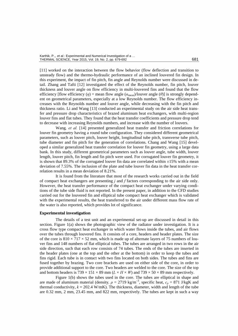
[11] worked on the interaction between the flow behavior (flow deflection and transition to unsteady flow) and the thermo-hydraulic performance of an inclined louvered fin design. In this experiment, the impact of fin pitch, fin angle and Reynolds number were discussed in de-tail. Zhang and Tafti [12] investigated the effect of the Reynolds number, fin pitch, louver thickness and louver angle on flow efficiency in multi-louvered fins and found that the flow efficiency [flow efficiency (η) = mean flow angle (αmean)/louver angle (θ)] is strongly depend-ent on geometrical parameters, especially at a low Reynolds number. The flow efficiency in-creases with the Reynolds number and louver angle, while decreasing with the fin pitch and thickness ratio. Li and Wang [13] conducted an experimental study on the air side heat trans-fer and pressure drop characteristics of brazed aluminum heat exchangers, with multi-region louver fins and flat tubes. They found that the heat transfer coefficients and pressure drop tend to decrease with increasing Reynolds numbers, and increase with the number of louvers.
Wang, et al. [14] presented generalized heat transfer and friction correlations for louver fin geometry having a round tube configuration. They considered different geometrical parameters, such as louver pitch, louver height, longitudinal tube pitch, transverse tube pitch, tube diameter and fin pitch for the generation of correlations. Chang and Wang [15] devel-oped a similar generalized heat transfer correlation for louver fin geometry, using a large data bank. In this study, different geometrical parameters such as louver angle, tube width, louver length, louver pitch, fin length and fin pitch were used. For corrugated louver fin geometry, it is shown that 89.3% of the corrugated louver fin data are correlated within ±15% with a mean deviation of 7.55%. The inclusion of the plate and tube louver fin data in the heat transfer cor-relation results in a mean deviation of 8.21%.
It is found from the literature that most of the research works carried out in the field of compact heat exchangers are presenting j and f factors corresponding to the air side only. However, the heat transfer performance of the compact heat exchanger under varying condi-tions of the tube side fluid is not reported. In the present paper, in addition to the CFD studies carried out for the louvered fin and elliptical tube compact heat exchanger which is validated with the experimental results, the heat transferred to the air under different mass flow rate of the water is also reported, which provides lot of significance.
Experimental investigation
The details of a test unit and an experimental set-up are discussed in detail in this section. Figure 1(a) shows the photographic view of the radiator under investigation. It is a cross flow type compact heat exchanger in which water flows inside the tubes, and air flows over the tubes through louvered fins. It consists of a core, headers and header plates. The size of the core is 810 × 717 × 52 mm, which is made up of alternate layers of 75 numbers of lou-ver fins and 148 numbers of flat elliptical tubes. The tubes are arranged in two rows in the air side direction, such that each row consists of 74 tubes. The ends of the tubes are inserted in the header plates (one at the top and the other at the bottom) in order to keep the tubes and fins rigid. Each tube is in contact with two fins located on both sides. The tubes and fins are fused together by brazing. Two core brackets are used on either side of the core, in order to provide additional support to the core. Two headers are welded to the core. The size of the top and bottom headers is 739 × 151 × 89 mm (L × H × W) and 739 × 50 × 89 mm respectively.
Figure 1(b) shows the tubes used in the core. The tubes are elliptical in shape and are made of aluminum material (density, ρ = 2719 kg/m–3, specific heat, cp = 871 J/kgK and thermal conductivity, k = 202.4 W/mK). The thickness, diameter, width and length of the tube are 0.32 mm, 2 mm, 23.45 mm, and 822 mm, respectively. The tubes are kept in such a way

Karthik, P.,, et al.: Experimental and Numerical Investigation of a … 682 THERMAL SCIENCE, Year 2015, Vol. 19, No. 2, pp. 679-692
that the width is parallel to the thickness of the core. The distance between each row of the tube is 4 mm. The tube pitch is equal to 7.68 mm.
Figure 1. Details of radiator test unit; (a) photographic view of the radiator, (b) elliptical tubes, (c) corrugated louvered fin, (d) details of louver, (e) schematic sketch of radiator with parts identified; 1 – water filling hole, 2 – cold water to engine, 3 – recycling water to engine, 4 – elliptical tube, 5 – fin, 6 – bottom header plate, 7 – bottom header, 8 – hot water from radiator, 9 – drain cock, 10 – core bracket
Figure 1(c) shows the corrugated louvered fin used in the core. These fins are also made of aluminum. The louvers are trapezoidal in shape and there are 27 louvers on each side of the fin. The length, width, height and thickness of the fin are 52 mm, 7.68 mm, 810 mm, and 0.1 mm, respectively. The fins are kept in between the tubes in such a way, that the length of the fin is parallel to the width of the tube. The fin pitch, louver pitch, and louver gap are 3 mm, 1.2 mm, and 0.284 mm, respectively. The details of the louver geometry and critical di-mensions are shown in fig. 1(d). Figure 1(e) shows the schematic sketch of the compact heat exchanger with corrugated louvered fins and flat elliptical tubes. The major components asso-ciated with the radiator are indicated in fig. 1(e).
Details of experimental set-up
Figure 2 shows the test rig available at M/s Halgona Radiators Private Limited, Bangalore, India, with provisions to supply high pressure air at ambient temperature to the cold side of the test unit. This air supply line contains a blower, dampers and necessary in-struments. The test rig also has provision for necessary inlet condition for water, which is supplied through the tube (hot) side of the test unit. Water is supplied through a pipe line that starts from the boiler, followed by a centrifugal pump, flow control valve and converging pipe line, to match the entry dimensions of inlet configuration to be tested, as shown in fig. 2.
During the experiments, the mass flow rate of the water is varied from 75 to 135 lpm using the flow control valve. For each mass flow rate of water, the air velocity is varied from 2.5 to 7.5 m/s by adjusting the damper positions using a lever mechanism. The temperature of the water at the outlet, the inlet and outlet temperatures of the air, the pressure drop across the air and water sides, are measured for different mass flow rates. Based on the above data, the perfor-mance of the test unit is estimated and the corresponding results are plotted in graphical form.

Karthik, P.,, et al.: Experimental and Numerical Investigation of a … THERMAL SCIENCE, Year 2015, Vol. 19, No. 2, pp. 679-692 683
Figure 2. Schematic layout of the test rig
1 – water level indicator, 2 – boiler, 3 – mud box, 4 – pump, 5 – motor, 6 – flow control valve, 7 – radiator (test piece), 8 – tunnel, 9 – transition piece, 10 – circular passage, 11 – outlet duct, 12 – blower, 13 – shaft, 14 – pulley, 15 – belt, 16 – motor, FL – floor level, EH – electrical heaters (12 nos), P1, P2 – pressure gauge, G1-G5 – gate valves
The inlet and outlet temperatures of the air-steam mixture are measured using two T-type thermocouple meshes placed upstream and downstream of the test section. These ther-mocouple meshes are inserted from both top and bottom surface of the test section at an average span wise interval of 40 mm. The inlet measuring mesh consists of nine thermocouples while the outlet mesh contains twelve thermocouples. These 0.3 mm diameter thermocouples are pre-calibrated with an accuracy of 0.2 °C. These data signals are recorded individually and then av-eraged. The velocity of air driven by a centrifugal blower is measured using the portable ane-mometer with an uncertainty of 0.14%. The velocity of air is measured at 12 points on the up-stream side of the test radiator and then averaged. The air pressure drop across the heat ex-changer is measured using a pressure transducer calibrated to an accuracy of ±0.09% of full scale. One of these transducers is placed in the entrance region and the other is placed after the laminar flow element. To obtain the air side pressure drop measurements through the louvered array and laminar flow element, more number of samples are average for each air velocity.
The hot fluid in this heat exchanger is water. A centrifugal pump circulates water into the heat exchanger. The water is heated in the boiler by 12 electrical heaters. Every heater has a maximum input of 6 kW and is controlled by variable transformers. The inlet and outlet water temperatures are measured by two pre-calibrated K type thermocouples with an uncertainty of 0.1 °C. The water volume flow rate is measured with a MAGFLOW 5100W flow meter with an average error of 0.5%. The pressure drop measurements in the water side are done by differen-tial pressure transducer and a manometer checks the accuracy of this measurement.
The measurements of temperature, pressure and flow rate are gathered using the data acquisition system. To minimize the heat lost to the surroundings, all components and pipe are insulated with a 10 mm thick glass wool layer.
Numerical simulation
Physical model
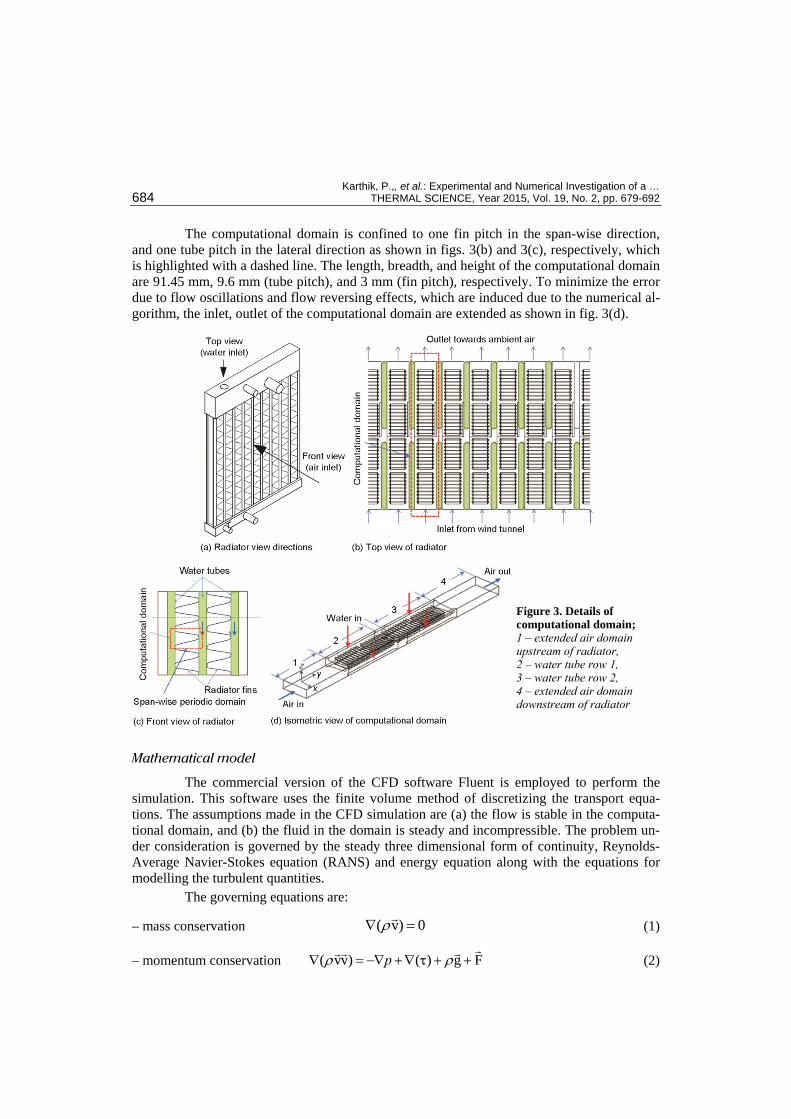
The computational domain considered for the CFD analysis is shown in fig. 3. Figure 3(a) identifies the front and top view directions of the radiator. Figure 3(b) shows the top view of the radiator, with the two rows of tubes shaded. The geometry periodicity of the radiator in the tube pitch-wise (lateral) direction can be easily observed. Figure 3(c) shows a small region of the radiator in the front view, where the fins positioned between the tubes are shown. The fin geometry indicates that it has a periodicity in the tube height-wise (span) direction.
Karthik, P.,, et al.: Experimental and Numerical Investigation of a … 684 THERMAL SCIENCE, Year 2015, Vol. 19, No. 2, pp. 679-692
The computational domain is confined to one fin pitch in the span-wise direction, and one tube pitch in the lateral direction as shown in figs. 3(b) and 3(c), respectively, which is highlighted with a dashed line. The length, breadth, and height of the computational domain are 91.45 mm, 9.6 mm (tube pitch), and 3 mm (fin pitch), respectively. To minimize the error due to flow oscillations and flow reversing effects, which are induced due to the numerical al-gorithm, the inlet, outlet of the computational domain are extended as shown in fig. 3(d).
Figure 3. Details of computational domain; 1 – extended air domain upstream of radiator, 2 – water tube row 1, 3 – water tube row 2, 4 – extended air domain downstream of radiator
Mathematical model
The commercial version of the CFD software Fluent is employed to perform the simulation. This software uses the finite volume method of discretizing the transport equa-tions. The assumptions made in the CFD simulation are (a) the flow is stable in the computa-tional domain, and (b) the fluid in the domain is steady and incompressible. The problem un-der consideration is governed by the steady three dimensional form of continuity, Reynolds-Average Navier-Stokes equation (RANS) and energy equation along with the equations for modelling the turbulent quantities.
The governing equations are:
– mass conservation ( v) 0ρ∇ = (1)
– momentum conservation ( vv) ( ) g Fpρ ρ∇ = −∇ +∇ + +τ (2)

Karthik, P.,, et al.: Experimental and Numerical Investigation of a … THERMAL SCIENCE, Year 2015, Vol. 19, No. 2, pp. 679-692 685
– energy conservation [v( )] [ ( v)]E p k Tρ∇ + = ∇ ∇ + τ (3)
where 2
2ρ
ρ⎛ ⎞
= − +⎜ ⎟⎜ ⎟⎝ ⎠
p vE h (4)
The temperature distribution inside the solid regions of the model, such as tube walls and fin, is obtained by solving the energy equation:
∇ (ks∇Ts) = 0 (5)
The equation will allow to obtain the temperature, not only inside the fin, but also along its surface.
The turbulent quantities are modeled using the k-ω model to capture the large fluid strains more effectively.
Boundary conditions
The analysis is carried out by considering the water flowing through the tube and the simultaneous heat transfer occurs through the finned surface. Hence, conjugate analysis is performed by estimating the conduction and convection parameter using the solver based on the local flow and thermal conditions.
The various boundary conditions used for the present CFD analysis where both hot water and cold air make cross flow in the domain are:
(1) Inlet and outlet conditions: – Air side
Inlet – v = vin, u = 0, and w = 0 T = Tin,a Outlet – p = patm T = Tout (applicable only to the grid cells where back flow occurs).
– Water side Inlet – w = –win, u = 0, and v = 0 T = Tin,w Outlet – T = Tout (applicable only to the grid cells where back flow occurs).
(2) Boundary surfaces – upper and lower side = periodicity – left side and right side = periodicity
(3) Tube, fin and louver walls – u = 0, v = 0, and w = 0 – no separate temperature boundary condition is needed, as the solver calculates
the thermal information in a coupled way. The computational domain is extended both upstream and downstream of the core,
and the potential back flow is avoided. Initially, the mesh density finalization is done for the computational domain. Tetrahedral mesh elements are used for meshing the computational model. The surface mesh element sizes are controlled to obtain fine mesh elements close to the fin and louvers. The mesh grows in size outward from the fin, and louver to the tubes and extended domains. Different mesh configurations, starting with very coarse to very fine are taken at a particular Reynolds number, and analysed using the Fluent. Three different grids were tested with 0.6, 1.63, and 2.26 million cells, using different meshing parameters. The re-
Karthik, P.,, et al.: Experimental and Numerical Investigation of a … 686 THERMAL SCIENCE, Year 2015, Vol. 19, No. 2, pp. 679-692
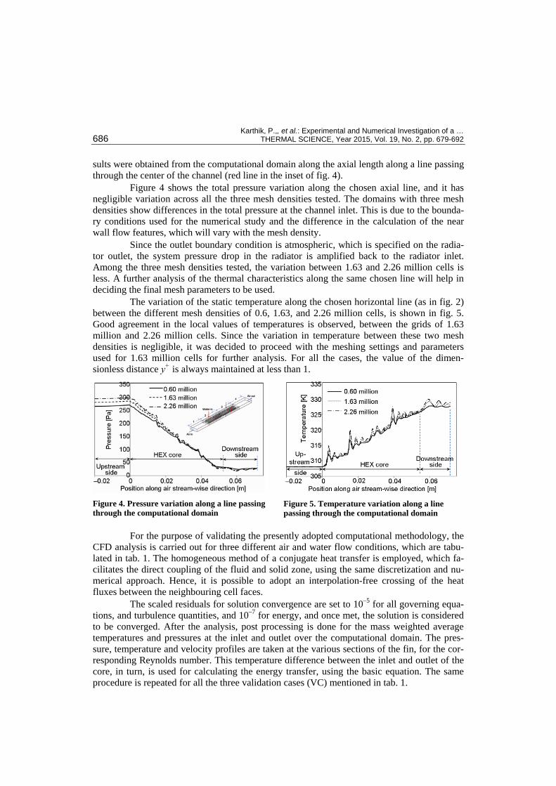
sults were obtained from the computational domain along the axial length along a line passing through the center of the channel (red line in the inset of fig. 4).
Figure 4 shows the total pressure variation along the chosen axial line, and it has negligible variation across all the three mesh densities tested. The domains with three mesh densities show differences in the total pressure at the channel inlet. This is due to the bounda-ry conditions used for the numerical study and the difference in the calculation of the near wall flow features, which will vary with the mesh density.
Since the outlet boundary condition is atmospheric, which is specified on the radia-tor outlet, the system pressure drop in the radiator is amplified back to the radiator inlet. Among the three mesh densities tested, the variation between 1.63 and 2.26 million cells is less. A further analysis of the thermal characteristics along the same chosen line will help in deciding the final mesh parameters to be used.
The variation of the static temperature along the chosen horizontal line (as in fig. 2) between the different mesh densities of 0.6, 1.63, and 2.26 million cells, is shown in fig. 5. Good agreement in the local values of temperatures is observed, between the grids of 1.63 million and 2.26 million cells. Since the variation in temperature between these two mesh densities is negligible, it was decided to proceed with the meshing settings and parameters used for 1.63 million cells for further analysis. For all the cases, the value of the dimen-sionless distance y+ is always maintained at less than 1.
Figure 4. Pressure variation along a line passing through the computational domain
Figure 5. Temperature variation along a line passing through the computational domain
For the purpose of validating the presently adopted computational methodology, the CFD analysis is carried out for three different air and water flow conditions, which are tabu-lated in tab. 1. The homogeneous method of a conjugate heat transfer is employed, which fa-cilitates the direct coupling of the fluid and solid zone, using the same discretization and nu-merical approach. Hence, it is possible to adopt an interpolation-free crossing of the heat fluxes between the neighbouring cell faces.
The scaled residuals for solution convergence are set to 10–5 for all governing equa-tions, and turbulence quantities, and 10–7 for energy, and once met, the solution is considered to be converged. After the analysis, post processing is done for the mass weighted average temperatures and pressures at the inlet and outlet over the computational domain. The pres-sure, temperature and velocity profiles are taken at the various sections of the fin, for the cor-responding Reynolds number. This temperature difference between the inlet and outlet of the core, in turn, is used for calculating the energy transfer, using the basic equation. The same procedure is repeated for all the three validation cases (VC) mentioned in tab. 1.

Karthik, P.,, et al.: Experimental and Numerical Investigation of a … THERMAL SCIENCE, Year 2015, Vol. 19, No. 2, pp. 679-692 687
Results and discussions
Experimental results
Figure 6 shows the exper-imental variation of the air side temperature difference between the radiator inlet and exit, with respect to the air velocity, for different water flow rates. From the figure, it is found that the increase in air velocity, decreases the air temperature difference across the radiator which is due to the higher mass of air associated with the higher velocity. Further, at a given air velocity, the increase in the water flow rate increases the air side tem-perature difference. However, this difference is marginal at lower air velocity, and increases as the air velocity increases. The increase in the flow rate of water increases the total heat ca-pacity of the water stream. The higher heat transfer coefficient at higher velocities increases the heat absorption from the water, which increases the temperature difference of the air be-tween the inlet and outlet. At lower velocities, the heat transfer coefficient is low. Hence, the air side heat transfer resistance is dominant, and the increase in the mass flow rate of water has a negligible effect in increasing the temperature difference in the air.
Figure 7 shows the experimental variation of the heat absorption by the air with re-spect to the air velocity for different water flow rates. It is seen from the figure that the heat absorbed is low at a lower velocity of the air, and it increases with an increase in the air veloc-ity. This is due to the increase in the heat transfer coefficient associated with the increase in air velocity. Further increase in the mass flow rate of water has a better influence in increasing the heat transfer at higher velocities of air. This is due to the increase in the air velocity which has a greater influence in increasing the overall heat transfer coefficient than the effect due to the increase in the mass flow rate of water.
Figure 6. Variation of air-side temperature rise between the inlet and the exit with inlet air velocity
Figure 7. Variation of heat absorption with air velocity – experiments
Further, it is observed from the fig. 7 that the increase in the heat absorbed by the air shows a decreasing trend at lower mass flow rate of water, as the air velocity increases. The in-crease in air velocity increases the heat transfer co-efficient of the airside and mass flow rate of air that increases the heat absorbing capacity of the air appreciably. However, at lower mass flow rate of water, since the heat capacity of the water is not sufficient to match with the heat absorbing capacity of the air, the increase in heat absorbed by the air shows a decreasing trend.
Table 1. Summary of data sets used for numerical simulations
Validation cases
Air velocity [ms–1]
Inlet air temperature
[K]
Water flow rate [kgs–1]
Inlet water temperature
[K]
VC1 2.5 310 0.004215 363
VC2 5.6 308 0.006181 363
VC3 7.5 302 0.007586 363

Karthik, P.,, et al.: Experimental and Numerical Investigation of a … 688 THERMAL SCIENCE, Year 2015, Vol. 19, No. 2, pp. 679-692
Validation of numerical analysis
Figure 8 shows the comparison of the air side temperature difference obtained in the CFD analysis, with respect to the experimental data. The percent deviations of the tempera-ture values between the experimental and CFD results in the VC – 1, 2, and 3 are 11.05%, 14.28%, and 15.89%, respectively. The deviation could be due to the uncertainties in the ex-perimental measurements and also to the numerical errors attributed to the turbulence model employed. However, these deviations are within the acceptable limits.
In order to understand the local variation of the flow properties within the flow domain, a few vertical lines (VL) are created within the domain on a vertical plane (VP) as shown in fig. 9(a).
The plane considered passes through the mid transverse location, which is in the mid plane between the flat elliptical water tubes. The lines are shown in detail in fig. 9(b). VL1 is po-sitioned such that it just touches the fin geometry at the radiator inlet. The subsequent lines on the VP are at a spacing of 10 mm from VL1. A total
of 6 lines were created to plot and understand the local variation of the flow and thermal properties within the channel.
The local variation of the velocity magnitude along the chosen VL1 to VL6 is plotted in fig. 9(c), for the data extracted from the case VC2. The abscissa of all the plots has the same range as that of the first plot along VL1. The points 1 and 2 highlighted with dots along VL1 show zero velocity. The velocity value drops to zero where the line touches the fin and louver surface, and reaches a higher velocity in the region away from the wall. In the region between the fin surfaces, flow acceleration occurs, which is due to an increase in the velocity of air ob-served from fig. 9(c).
Figure 9. Variation of local velocity and temperature variation along the vertical lines in various locations of the mid vertical plane; (a) location of mid vertical plane, (b) location of vertical lines on the plane, (c) local velocity magnitude [ms–1] variation along the vertical lines – VC2, (d) local temperature [K] variation along the vertical lines – VC2
310 330 350
VL3 VL4 VL5 VL6
300 320 340
VL2
VL3 VL4 VL5 VL6VL1VL2
1
2
3
4
0 5 10(c) (d)
1
2
VL1 0.00350.0030.00250.0020.00150.0010.00050
0.00350.0030.00250.0020.00150.0010.00050
Figure 8. Comparison of air side temperature difference [K], between CFD and experiments
Karthik, P.,, et al.: Experimental and Numerical Investigation of a … THERMAL SCIENCE, Year 2015, Vol. 19, No. 2, pp. 679-692 689
Similarly four zero velocity points 1-4 are observed along VL2, as the air touches the louvers at four points as shown in fig. 9(b). The variation of velocity shown at the six lo-cations along the stream-wise direction indicates the high turbulent nature of the flow within the domain.
Figure 9(d) shows the local variation of the temperature along the above mentioned six VL. The values of abscissa for VL1 to VL5 are same as that of VL1. The temperature var-iation along VL1 shows the maximum values at locations 1 and 2, which are shown in fig. 9(c), where VL touches the fin surface. Similar maximum temperature values are observed along VL6. Higher temperature values are observed along VL1 and VL6, due to the absence of the louvers along these VL. However, the variation along the other VL (2 to 5) show lesser deviation due to the higher surface area of the louvers.
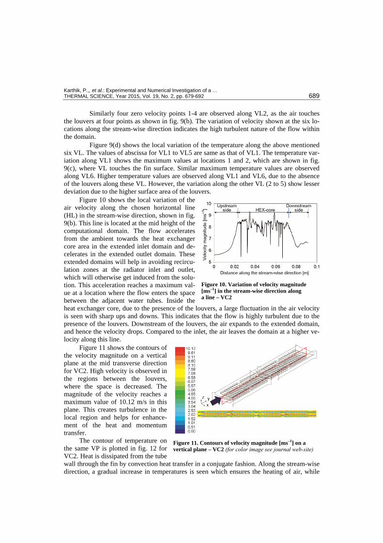
Figure 10 shows the local variation of the air velocity along the chosen horizontal line (HL) in the stream-wise direction, shown in fig. 9(b). This line is located at the mid height of the computational domain. The flow accelerates from the ambient towards the heat exchanger core area in the extended inlet domain and de-celerates in the extended outlet domain. These extended domains will help in avoiding recircu-lation zones at the radiator inlet and outlet, which will otherwise get induced from the solu-tion. This acceleration reaches a maximum val-ue at a location where the flow enters the space between the adjacent water tubes. Inside the heat exchanger core, due to the presence of the louvers, a large fluctuation in the air velocity is seen with sharp ups and downs. This indicates that the flow is highly turbulent due to the presence of the louvers. Downstream of the louvers, the air expands to the extended domain, and hence the velocity drops. Compared to the inlet, the air leaves the domain at a higher ve-locity along this line.
Figure 11 shows the contours of the velocity magnitude on a vertical plane at the mid transverse direction for VC2. High velocity is observed in the regions between the louvers, where the space is decreased. The magnitude of the velocity reaches a maximum value of 10.12 m/s in this plane. This creates turbulence in the local region and helps for enhance-ment of the heat and momentum transfer.
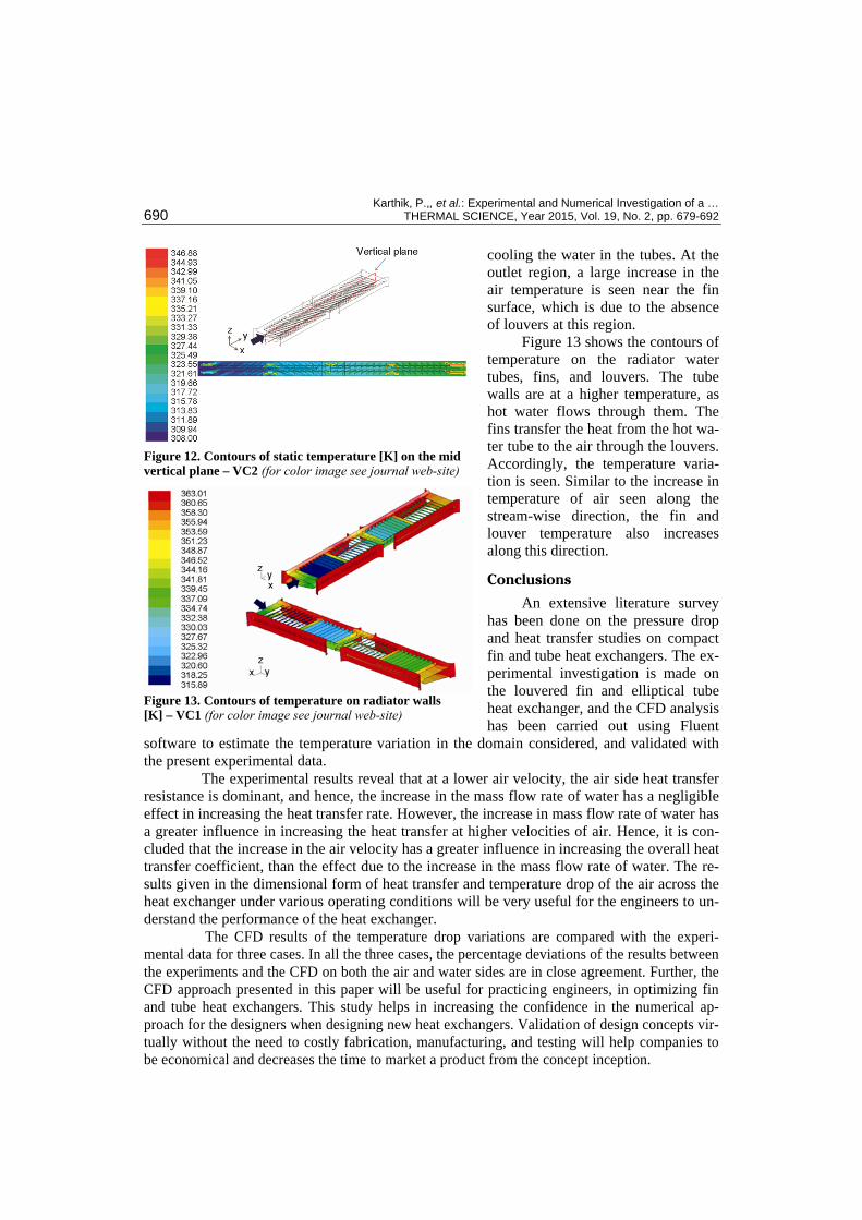
The contour of temperature on the same VP is plotted in fig. 12 for VC2. Heat is dissipated from the tube wall through the fin by convection heat transfer in a conjugate fashion. Along the stream-wise direction, a gradual increase in temperatures is seen which ensures the heating of air, while
Figure 10. Variation of velocity magnitude [ms–1] in the stream-wise direction along a line – VC2
Figure 11. Contours of velocity magnitude [ms–1] on a vertical plane – VC2 (for color image see journal web-site)
Karthik, P.,, et al.: Experimental and Numerical Investigation of a … 690 THERMAL SCIENCE, Year 2015, Vol. 19, No. 2, pp. 679-692
cooling the water in the tubes. At the outlet region, a large increase in the air temperature is seen near the fin surface, which is due to the absence of louvers at this region.
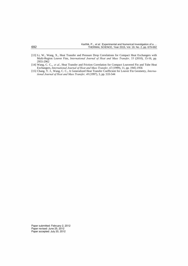
Figure 13 shows the contours of temperature on the radiator water tubes, fins, and louvers. The tube walls are at a higher temperature, as hot water flows through them. The fins transfer the heat from the hot wa-ter tube to the air through the louvers. Accordingly, the temperature varia-tion is seen. Similar to the increase in temperature of air seen along the stream-wise direction, the fin and louver temperature also increases along this direction.
Conclusions
An extensive literature survey has been done on the pressure drop and heat transfer studies on compact fin and tube heat exchangers. The ex-perimental investigation is made on the louvered fin and elliptical tube heat exchanger, and the CFD analysis has been carried out using Fluent
software to estimate the temperature variation in the domain considered, and validated with the present experimental data.
The experimental results reveal that at a lower air velocity, the air side heat transfer resistance is dominant, and hence, the increase in the mass flow rate of water has a negligible effect in increasing the heat transfer rate. However, the increase in mass flow rate of water has a greater influence in increasing the heat transfer at higher velocities of air. Hence, it is con-cluded that the increase in the air velocity has a greater influence in increasing the overall heat transfer coefficient, than the effect due to the increase in the mass flow rate of water. The re-sults given in the dimensional form of heat transfer and temperature drop of the air across the heat exchanger under various operating conditions will be very useful for the engineers to un-derstand the performance of the heat exchanger.
The CFD results of the temperature drop variations are compared with the experi-mental data for three cases. In all the three cases, the percentage deviations of the results between the experiments and the CFD on both the air and water sides are in close agreement. Further, the CFD approach presented in this paper will be useful for practicing engineers, in optimizing fin and tube heat exchangers. This study helps in increasing the confidence in the numerical ap-proach for the designers when designing new heat exchangers. Validation of design concepts vir-tually without the need to costly fabrication, manufacturing, and testing will help companies to be economical and decreases the time to market a product from the concept inception.
Figure 12. Contours of static temperature [K] on the mid vertical plane – VC2 (for color image see journal web-site)
Figure 13. Contours of temperature on radiator walls [K] – VC1 (for color image see journal web-site)

Karthik, P.,, et al.: Experimental and Numerical Investigation of a … THERMAL SCIENCE, Year 2015, Vol. 19, No. 2, pp. 679-692 691
Nomenclature cp – specific heat capacity, [kJkg–1K–1] E – energy, [kJ] F – external forces, [Nm–1] g – body force H – height, [mm] h – specific entalpy, [Jkg–1] k – thermal conductivity, [Wm–1K–1] L – length, [mm] p – pressure, [bar] T – absolute temperature, [K] u – velocity of the fluid along x direction, [ms–1] v – velocity of the fluid along y direction, [ms–1] W – width, [mm] w – velocity of the fluid along z direction, [ms–1]
Greek symbols
θ – louver angle, [deg]
ρ – density, [kgm–3] (air = 1.1; water = 1000) τ – stress matrix
Acronyms HEX – heat exchanger HL – horizontal line lpm – liters per minute VC – validation case VL – vertical line VP – vertical plane
Subscripts a – air in – inlet out – outlet w – water
Acknowledgments
The authors gratefully acknowledge their debt to M/s. Halgona Radiators Pvt. Lim-ited, Bangalore, India, for providing the facility for wind tunnel testing.
References [1] Borrajo-Pelaez, R., et al., A Three-Dimensional Numerical Study and Comparison between the Air Side
Model and the Air/Water Side Model of a Plain Fin and Tube Heat Exchanger, Applied Thermal Engi-neering, 30 (2010), 13, pp. 1608-1615
[2] Sahin, H. M.,, et al., 3-D Numerical Study on Correlation between Variable Inclined Fin Angles and Thermal Behavior in Plate Fin-Tube Heat Exchanger, Applied Thermal Engineering, 27 (2007), 11, pp. 1806-1816
[3] Wen, M. Y., Ho, C. Y., Heat Transfer Enhancement in Fin and Tube Heat Exchanger with Improved Fin Design, Applied Thermal Engineering, 29 (2009), 5, pp. 1050-1057
[4] Yan, W. M., Sheen, P. J., Heat Transfer and Friction Characteristics of Fin and Tube Heat Exchangers, International Journal of Heat and Mass Transfer, 43 (2000), 9, pp. 1651-1659
[5] Wolf, I.,, et al., A Numerical and Experimental Analysis of Heat Transfer in a Wavy Fin and Tube Heat Exchanger, Energy and the Environment (2006), 1, pp. 91-101
[6] Tang, L. H.,, et al., Experimental and Numerical Investigation on Air Side Performance of Fin and Tube Heat Exchangers with Various Fin Patterns, Experimental Thermal and Fluid science, 33 (2009), 5, pp. 818-827
[7] Wang, C. C.,, et al., Flow Visualization of Annular and Delta Winlet Vortex Generators in Fin and Tube Heat Exchanger Application, International Journal of Heat and Mass Transfer, 45 (2002), 18, pp. 3803-3815
[8] Fiebig, M.,, et al., Local Heat Transfer and Flow Losses in Fin and Tube Heat Exchangers with Vortex Generators: A Comparison of Round and Flat Tubes, Experimental Thermal and Fluid Science, 8 (1994), 1, pp. 35-45
[9] Leu, J. S.,, et al., Heat Transfer and Fluid Flow Analysis in Plate-Fin and Tube Heat Exchangers with a Pair of Block Shape Vortex Generators, International Journal of Heat and Mass Transfer, 47 (2004), 19-20, pp. 4327-4338
[10] Leu, J. S., Liu, M. S., A Numerical Investigation of Louvered Fin and Tube Heat Exchangers Having Circular and Oval Tube Configurations, International Journal of Heat and Mass Transfer, 44 (2001), 22, pp. 4235-4243
[11] Joen, C. T.,, et al., Interaction between Mean Flow and Thermo-Hydraulic Behaviour in Inclined Louver Fins, International Journal of Heat and Mass Transfer, 54 (2011), 4, pp. 826-837
[12] Zhang, X., Tafti, D. K., Flow Efficiency in Multi-Louvered Fins, International Journal of Heat and Mass Transfer, 46 (2003), 10, pp. 1737-1750
Karthik, P.,, et al.: Experimental and Numerical Investigation of a … 692 THERMAL SCIENCE, Year 2015, Vol. 19, No. 2, pp. 679-692
[13] Li, W., Wang, X., Heat Transfer and Pressure Drop Correlations for Compact Heat Exchangers with Multi-Region Louver Fins, International Journal of Heat and Mass Transfer, 53 (2010), 15-16, pp. 2955-2962
[14] Wang, C. C.,, et al., Heat Transfer and Friction Correlation for Compact Louvered Fin and Tube Heat Exchangers, International Journal of Heat and Mass Transfer, 42 (1999), 11, pp. 1945-1956
[15] Chang, Y. J., Wang, C. C., A Generalized Heat Transfer Coefficient for Louver Fin Geometry, Interna-tional Journal of Heat and Mass Transfer, 40 (1997), 3, pp. 533-544
Paper submitted: February 2, 2012 Paper revised: June 25, 2012 Paper accepted: July 20, 2012