PART- B - Bharat Heavy Electricals Ltd. · 7.0 Indicative PV array layout 8.0 Site photos ......
30
PART- B List of Exhibits 1.0 Available land Drawing 2.0 Schematic drawing of Power evacuation system 3.0 Topographical Survey of the proposed area a) Topographical Survey of the proposed solar plant at PTS Stage-2 b) Topographical Survey of the proposed solar plant at Patharmuda 4.0 Geotechnical studies of the proposed area 5.0 List of mandatory spares 6.0 Indicative Single Line Diagram 7.0 Indicative PV array layout 8.0 Site photos 9.0 Data sheet of PV module 10.0 FQP for Civil Works
Transcript of PART- B - Bharat Heavy Electricals Ltd. · 7.0 Indicative PV array layout 8.0 Site photos ......

PART- B
List of Exhibits
1.0 Available land Drawing
2.0 Schematic drawing of Power evacuation system
3.0 Topographical Survey of the proposed area
a) Topographical Survey of the proposed solar plant at PTS Stage-2
b) Topographical Survey of the proposed solar plant at Patharmuda
4.0 Geotechnical studies of the proposed area
5.0 List of mandatory spares 6.0 Indicative Single Line Diagram 7.0 Indicative PV array layout 8.0 Site photos 9.0 Data sheet of PV module 10.0 FQP for Civil Works

W.T.P
S
.P
O
O
C
L
U
B
B
L
D
G
.
V
.I.P
G
U
E
S
T
H
O
U
S
E
B
U
N
G
L
O
W
G
.M
'S
'D
' T
Y
P
E
Q
T
R
S
.
P
A
R
K
T
/S
A
D
M
N
.
B
L
D
G
.
D
.H
W
.T
G
R
O
U
N
D
W
A
T
E
R
T
A
N
KE
L
E
C
T
. M
A
IN
T
O
F
F
S
/S
S
H
O
P
P
IN
G
P
A
R
K
'A
' T
Y
P
E
Q
T
R
S
.
'B
' T
Y
P
E
Q
T
R
S
.
S
/SA
T
M
B
L
D
G
.
P
A
R
K
N
U
R
S
E
R
Y
. S
C
H
O
O
L
'B
' T
Y
P
E
Q
T
R
S
.
'C
' T
Y
P
E
Q
T
R
S
.
S
H
O
O
P
IN
G
C
O
M
P
L
E
X
G
A
R
R
A
G
E
S
G
A
R
R
A
G
E
S
F
O
O
T
B
A
L
L
B
A
S
K
E
T
B
A
L
L
V
O
L
L
E
Y
K
A
B
A
D
I
L
A
W
N
T
E
N
IS
E
X
T
G
. H
E
L
IP
A
D
R
. C
C
O
N
S
T
N
.
O
F
1
4
N
o
s
.
'
D
'
T
Y
P
E
Q
T
R
S
F
O
R
-
S
T
-
I
I
F
O
R
-
S
T
-
I
I
C
O
N
S
T
N
.
O
F
2
4
N
o
s
.
'
D
'
T
Y
P
E
Q
T
R
S
P
R
O
P
O
S
E
D
P
A
R
K
P
A
R
K
(
1
4
4
N
o
s
.
+
9
4
N
o
s
.
)
=
2
3
8
S
T
-
I
I
B
-
T
Y
P
E
Q
T
R
S
.
H
O
S
P
IT
A
L
S
W
E
A
G
E
T
R
E
A
T
M
E
N
T
P
L
A
N
T
C
O
M
P
L
E
X
S
H
O
O
P
IN
G
H
.S
.S
'A
' T
Y
P
E
Q
T
R
S
.
H
S
S
S
/S
G
A
R
R
A
G
E
S
B
A
L
-
B
H
A
W
A
N
G
R
E
E
N
P
L
A
N
T
1
2
3
4
9
8
7
12
1
1
10
V
IV
III
V
I
V
II
V
II
II
I
6
5
S
T
- II
C
O
N
S
T
N
. O
F
2
8
N
o
s
. 'C
' T
Y
P
E
Q
T
R
S
.
5
4
3
2
1
6
.5
6
.5
3189.634E
287.503S
78.82
B.P-19
B.P-18
G.P-19
2525.000E
150.000S
79.00
C
E
N
T
R
A
L
P
A
R
K
ST 12
ST 13
2679.588E
606.186S
R
A
N
G
A
B
E
D
A
V
I
L
L
A
G
E
G
O
C
H
H
A
R
A
R
E
A
F
O
R
2125.000E
50.000S
B.P-13
CAR G
ARRAGES
V
I
L
L
A
G
E
R
A
N
G
A
B
E
D
A
B' TYPE Q
TRS
TRANING CENTRE
79.62
2525.000S
325.000S
G.P-18
B.P-21
B.P-22
EXITING BOUNDARY WALL
P
R
O
P
O
S
E
D
S
W
IM
M
IN
G
P
O
O
L
82.45
82.45
82.45
82.45
82.45
81.45
81.95
81.95
81.45
82.45
81.45
81.95
81.25
81.60
81.25
81.60
81.25
81.60
81.25
81.25
81.00
81.00
81.25
81.25
81.25
81.25
81.00
81.00
81.25
81.25
81.00
81.25
81.25
81.25
81.25
81.25
81.25
81.50
81.50
81.50
EXITING BOUNDARY WALL
S
C
H
O
O
L
E
X
IT
IN
G
S
T
. M
A
R
R
Y
'S
76.00
7
6
.5
2
7
5
.6
7
7
3
.2
2
7
5
.7
0
7
7
.6
1
7
7
.7
9
7
5
.2
4
7
9
.0
8
75.00
7
5
.9
7
7
6
.
3
4
77.00
VILLAGE GODASILA
B.P-17
7
6
.1
6
ELECTRIC LINE
7
5
.0
0
7
9
.0
47
5
.8
8
76.00
2400.000E
25.000S
G.P-17 7
9
.0
0
8
0
.0
0
7
9
.6
8
8
0
.7
5 8
0
.4
0
8
0
.0
4
7
7
.
0
0
2250.000E
50.000S
2250.000E
200.000S
2 Nos. D' TYPE (PGCIL)
36 Nos.B' TYPE 12 Nos. C' TYPE
G.P-13
85.08
8
1
.6
3
8
1
.6
9
8
0
.0
5
8
1
.5
2
8
8
.2
6
8
3
.1
7
8
6
.0
8
8
4
.0
1
STADIUM
PROPOSED
2400.000E
200.000S
G.P-16
36.11S
2498.70E
8
1
.1
9
8
2
.
0
0
COMPLEX
SHOPPING
PROPOSED
ST
E
.P
9
0
.5
7
8
0
.0
0
8
0
.4
3
8
0
.
0
0
7
9
.
0
0
B.P-20
8
0
.
0
0
7
9
.
0
0
8
1
.
0
0
2800.000E
250.000S
G.P-9
3000.000E
200.000S
G.P-4
G.P-3
PROPOSED LAND FOR
7
9
.
5
0
'D' TYPE QTRS.
164 UNITS
7
5
.
0
0
7
6
.
0
0
7
4
.
0
0
7
8
.
9
0
3189.634E
575.93S
G.P-1
80.0
0
80.0
0
7
2
.
2
6
80.0
0
7
1
.
9
8
7
3
.2
5
7
3
.
3
0
7
8
.6
0
7
3
.0
0
79.2
3
B.P-1
7
9
.2
3
76.90
7
9
.1
3
72.7
9
72.3
8
7
9
.2
6
7
9
.1
6
B.P-4
72.67
79.17
7
9
.2
6
7
9
.5
2
7
2
.2
7
7
2
.4
8
7
3
.1
6
73.87
72.29
72.30
73.64
7
2
.
7
6
73.81
75.75
7
4
.
0
0
7
2
.
9
0
7
3
.
0
0
7
5
.
0
0
7
6
.
5
2
78.12
7
5
.
0
9
7
5
.
6
8
7
4
.
8
6 7
5
.
1
9
B.P-5
B.P-6
7
6
.
5
8
7
5
.
1
9
7
4
.
2
4
7
5
.
6
4
75.0
0
76.0
0
7
7
.0
0
78.0
0
7
8
.
9
7
7
9
.
6
5
7
8
.
8
6
8
0
.
3
0
7
9
.
6
0
8
0
.
0
0
8
1
.
0
0
G.P-10
B.P-7
7
1
.
8
5
8
0
.
5
5
B.P-8
B.P-9
ST-9
8
1
.
5
8
8
0
.4
8
8
0
.0
0
8
1
.0
0
8
1
.3
1
8
2
.0
0
8
1
.8
5
R
O
A
D
8
2
.4
2
8
3
.0
0
8
4
.0
0
8
5
.0
0
9
6
.0
0
8
6
.4
3
9
2
.2
7
91.00
91.45
9
1
.0
09
0
.0
0
9
1
.3
0
9
0
.2
4
9
1
.0
0
8
8
.9
3
8
9
.9
0 8
9
.7
8
ST 11
8
9
.4
9
8
9
.1
1
8
8
.6
8
7
.6
1
8
7
.5
8
8
6
.7
8
96.00
9
6
.0
0
8
6
.0
0
RO
AD
8
7
.0
0
8
7
.6
4
8
7
.1
8
8
7
.0
0
B.P.-15
8
6
.
0
0
8
5
.1
0
8
5
.0
0
G.P.-11
8
4
.0
0
83.00
BOUNDARY WALL
B.P.-16
G.P.-14
8
2
.0
0
8
1
.4
2
82.00
81.00
8
1
.0
9
8
1
.4
6
7
6
.0
0
8
0
.2
6
7
7
.5
6
28
00
E
700N
600N
500N
400N
300N
200N
1100N
P.O - DEEPSHIKHA, KANIHA, Dist - ANGUL, ORISSA, Pin - 759147
E
M
E
R
G
E
N
C
Y
C
O
N
T
R
O
L
R
O
O
M
P
E
T
R
O
L
P
U
M
P
GATE-No-5 (MGR GATE)
V
i
l
l
-
K
A
N
I
H
A
P G
C
I L
H
V
D
C
S
T
A
T
I O
N
AR
1500
E
1200 N
1200
E
1079.469N
1189.175E
900 N
1134.30E
835.38N
1169.46E
825.00N
1152.6E
613.45N
N
T
P
C
P
E
R
M
A
N
E
N
T
T
O
W
N
S
H
I
P
600 N
1395.162E
489.477N
1311.30E
1313.54E
534.33N
SETTLING PIT
469.02N
579.926N
1440.940E
377.795N
500.00N
1250.00E
1335.00E
34
3.0
0N
335.00N
1315.58E
1207.02E
1039.96N
196.09N
300 N1414.30E
1425.93E
220.14N
293.30N
TO
P.T
.S.
T
O
K
A
R
A
D
E
I
V
I
L
L
A
G
E
1525.04E
HOUSE-III
267.75N
1305.00E
CRUSHER
140.00N
200.00N
1305.00E
1273.00E
TP-21
1442.12E
1430.00E
45.89N
1454.50E
50.00N
146.27N
000 N000 S
1470.53E
39.31N
22.81N
PH-III
TP-13
84.00M
76.00N
75.00N
1255.00E
48.00N
3191.00E
9.00N
1255.00E
CRUSHER
6.37S
1194.41E
HOUSE-II
1273.00E
1311.72E
T
O
G
A
D
A
S
I
L
A
V
I
L
L
A
G
E
189.54S
1486.14E
HOUSE
1295.25E
36.12S
95.5S
1283.0E
TP-10
PH-II
TP-2
TP-9
100.0S
1305.0E
1378.31E
260.98S
VIL
LA
GE
AR
EA
1388.49E
285.89S
241.41S
1454.36E
250.72S
1510.32E
1430.00E
349.56S
1400.51E
340.00S
296.78S
1406.46E
300 SCRUSHER
224.00S
1148.5E
310.00S
1305.00E
316.00S
1200.00E
ASH
BRICK
PLANT
321.00S
1255.00E
HOUSE-1
334.13S
MARKET
AREA
TR
AC
K H
OP
PE
R-III
T.H
. C
ON
T. R
M.
OC
CU
PIE
D
V
i
l
l
-
G
A
D
A
S
H
I
L
A
CIS
F C
OLO
NY
T.H
. C
ON
T. R
M.
92.50M1291.00E
1312.04E
460.40S
433.00S
1181.20E
PH-I
415.00S
1200.00E
TP-I
531.00S
TH
OR-I
1200.00E
1205.47E
TR
AC
K H
OP
PE
R-II
487.78S
461.00S
566.39S
496.23S
1339.26E
340.00S
1320.00E
600 S586.38S
1374.93E
BUS STAND
700.60S
1397.12E
92.50M
1224.00E
560.00S
639.00S
1065.75E
652.11S
1200.00E
612.53S
1200.00E
706.06S
1330.35E
693.75S
102.75E
637.80S
1330.56E
1339.33E
1255.00E
1397.12E
900 S
820.13S
1339.01E
766.00S
1200.00E
1344.37E
1342.00E
1055.61S
1325.49E
1055.61S
V
i
l
l
-
R
A
N
G
A
B
E
D
A
TR
AC
K H
OP
PE
R-I
744.76S
756.69S
1322.43E
1200 S
STORES
STORES
STORES
1417.89S
1413.10S
1131.02E
STORES
STORES
1500
E
TO MARKET
1200.00E
1200
E
1320.0E
1456.05 S
1326.80 E
1440.0S
1330.88E
V
ill-K
A
R
A
D
E
I &
K
A
T
E
N
I
IR
VIR
E
900
E
600
E
914.87E
1040.94N
GATE No-2
1127.527N
370.132E
369.256E
BOUNDARY WALL1023.47N
1025.47N
488.07E488.08E
1023.47N
470.08E
573.5E
414.28E
1132.47S
1010.00N
300
E
000
W00
0 E
1111.79N
378.45E
1090.5N
NGL1114.2N
52.5E
1081.54N
360.34E
1032.98N
1034N
98E
COOLING TOWER - 6B
254E
1118.0N
28.00W
51.319W
1069.08N
31.86W
1073.330N
62.908W
1010.69N
16.39W
20.37W
1107.708N
1171.50N
1141.48N
TK
I
300
W1200 N
600
W
1004.98E
890.03E
APPROACH FROM PTS
ASH
SIL
OS
GRADE SEPARATED
581.85E
1024.71N
1026.45N
488.07E
1032.07N
456.26E
1019.55N
392.35E
875.05N
582.21E
79.50M TO 80.0M
940.92E
658.64N
IN
CO
MIN
G/O
UT
CO
MIN
G
PIP
E &
C
AB
LE
R
AC
K
350E
26
0E
NGL
1010.00N
979N
136E
CT SWGR # 6
896N
COOLING TOWER - 6A98E
37.254E
1023.80N
29.44E
1055.096N
758N
98E
260.00E
655.00N
CT SWGR # 5
703N
136E
COOLING TOWER - 5B
83.00M
85.00M
534.74E
56
7E
572.24N
474.84N
535.0E
535.0E
524.18N
473.93E
550.47N
COAL SLURRY
TREATMENT PLANT
D
R
A
I
N
SETTLING PONDEFFLUENT
MFD
ES
P C
ON
T.
RO
OM
#
5
MFD
CHIMNEY
142.25N
480.5E
ES
P C
ON
T.
RO
OM
#
6
267.75N
704.70E
57
5.0
E
98E
COOLING TOWER - 5A
83.00M
85.00M210.00E
483.5N
141.00E
520N
495.5N
(44Mx36M)
BLDG.
SERVICE
555.00N
234.00E
547.00N
1.01E
43.20W
512.00N
514.00N
20.00E
492.97N
6.00E
493.80N
516.00N
292.00W
C.W
.P
.H
. III
434.00N
L.
C OF UNIT #6 (425.75N)
BOILER
10m34m
MILLS
TP
28
57
.7
5m
95
E
26
C OF UNIT #5 (329.75N)
L.
MILLS
TP
27
TP
96
.m
TG
HALL
W/T-6
439.44N
44.91W
444.01N
236.45W
411.26N
96.31W
436.60N
80.21W
410.49N
81.86W
363.00N
180.00W
369.16N
218.24W
376.5N
99.03W
102.63W
389.18N
445.5N
19.00E
65.5E
210.00E
A
33
7E
B C
ESP
ESP
620N
900 N
V
i
l
l
-
T
O
L
A
K
A
B
E
D
A
600 N
339.58W
381.98N
294.00W
425.21N
313.33W
410.78N
515.387W
384.25W
409.36N
375.98N
338.58W
W/T-5
363.00N
415.00W
380.00N
376.00W
432.00N
375.00N
306.00W
V
i
l
l
-
S
A
R
A
T
H
I
P
A
L
356.40E
GATE HOUSE1040.18N
1041.04N
704.70E
267.75N
CHP
SWGR
P.H
ASH SLURRY
SWGR ROOM
200N
704.70E
MFD
RO
OM
#
4
ES
P C
ON
T.
ST
OR
AG
EE
A
ND
SL
AK
IN
G P
LA
NT
SP
AC
E F
OR
L
IM
E
AS
H S
LU
RR
Y
TP-23
TP-22
9N
704.70E
F.G
.D
142.25N
480.5E 76N
704.70E
ES
P C
ON
T.
RO
OM
#
3
ASH WATER
P.H
MFD
10S
TP-15
SWGR
FOR AHP
20.75N
48.40E
85.00M
TRANSPORT
COMP. AIR
84.00MCHP
TP-14
SP
AC
E F
OR
T.O
.R
8
5.5
M
CHIMNEY
MILLS
BOTTOM ASH
TANKS & PH
MILLS
267.75N
337E
TP
24
TP
25
REG.CHLOR
13
9.5
m
AREAPLANT
BUILDING
AIR COMPRESSOR
CO
NT
OR
L
R
OO
M
CPUCW
L.
C OF UNIT #4 (190.25N)
TP
19
17
CWPH-I
DG
SET
SWPH
20
94.50M
166.0N
74.00E
85.00m
210N
C OF UNIT #3 (94.25N)
L.
BOILER
TP
TP
18
TG
TP
16
41.75N
10m34m
TP8
46.26S
9N.
17.65S
337.00E
MILLS
28N
DG
14
7m
5.14N
161.03E
210E
PO
WE
R
182.06E
HALL 17
92.00M
45.00N
CO
NT
RO
L
SW
ED
.
93.00W
RO
OM
17N
65.28N
19.50W
90.00m
75
.0
0W
29
.0
E
96
m
MILLS
ESP
ESP
CRUSHED COAL STOCK PILE
CRUSHED COAL STOCK PILE
CRUSHED COAL STOCK PILE
CRUSHED COAL STOCK PILE
714.00S
18
FM
OFFICE
156.95S
515.93E
CHP
TP-11
100.75S
471.04E
95
m
CH
IM
NE
Y
ESP-CR
626.00E
233.25S
CO
NT
. R
OO
M
172.04S
508.41E
ROOM
CH
P
156.95S
515.93E
85.00M
140.01S
638.20E
TP-12
35.00E
ASH PUMP
HOUSE
417.18E
ESP-CR191.21S
515.93E
41.85S
CONT.
COAL
85.00M
CHP WORKSHOP
277.21S
889.07E
(TEMPLE)299.75S
751.00E
224.75S
848.00E
IMAGEMANDAP
VISHNU
WORKSHOP
WALK WAY TO
VISHNU MURTHY
322.02S
862.82E
BHAVAN
BOILER
255.21S
AUX.
592.48E
285.5S
429.00E
197.24S
567.12E
291.5S
518.00E
349.75S
706.75E
346.8S
548.13E
D.M
PLANT
STAGE-I
D.M
70.40S
C.L. OF UNIT#2 (52.75S)
TP6
TP7
85.20S
ESP
65.94S
169.00E
DG
CH
SET
194.88E
194.88E
C.L. OF UNIT#1 (48.75S)
TP5
ESP
222.48S
74.00E
13
4E
20
4.0
0E
164.04E
63.81S
174.67E
184.08E
177.39S
19
1.5
S
193.00S
205.0E
149.50S
116.91S
M
M
M
94.50M
SWITCH YARD
C.W
.P
.H
PH.
& FIRST AID
270.90E
270S
STAGE-I
CL.
BLDG.
CHEM.
HOUSE
& WORKSHOP
241.42S
SERVICE BUILDING
CLARIFLOCCULATOR
RETAINING WALL
190.98E
SUMP
367.5S
PH.
STAGE-I
9000M
AS
H
W.P
.H
FILTER
277.712S
58.00E
277.81S
94.40E
305.39S
64.86E
392.00S
25
8.5
S
15
1.7
E99.14E
AMBULANCE
TP4
201.23S
CHEMICAL HOUSE
D.M
T
AN
KS
ACID & ALKALI
STORAGE AREA
362.00E
233.25S
SET
SU
B S
TA
TIO
N
417.17E
300 N
FENCING
58.00S
REMPORARY
000 S000 N
40
0 K
V S
WIT
CH
Y
AE
D
(S
TA
GE
-II)
43
0.0
0W
513.44W
120.08S
512.04W
119.99S
503.13W
19.46S
504.69W
140.09S
511.11W
139.76S
508.40W
192.380S
530.612W
300 S
275.00W
19.40S
(STAGE-II)
F.O. PRESSURISING P.H.
F.O. UNLOADING P.H
804.305E
45.45S
662.25E
404.50S
436.8S
548.13E85.00M
548.49S
528.00S
708.00E
566.65S
567.81E
603.96S
656.64E
PERM.STORE
578.78S
85.00M
CISF PASS
SECTION
F
IR
E
S
T
N
.
E
X
T
N
.
528.00S
758.00E
974.50E
712.88S
B
L
D
G
. &
723.00S
792.00E
F
IR
E
S
T
A
T
IO
N
2.50M WIDE
PATH (TYP)
603.96S
656.64E
CANTEEN
401.46E
616.92S
561.84E
H2 GEN.PLANT692.75S
581.93E
730.23S
654.22S
567.74E
530.00S
508.72E
579.40E
D.M
CLARIFIER
FIL
TE
R
AS
H W
AT
ER
CL
AR
IF
IE
RS
SLUDGE
PIT
CLARIFIER
CHEMICAL HOUSE
STAGE-II
ACID
DOSING
SLUDGE
THICKENER
427.00S
38.25E
547S
520..S
530.00S
83.99E
417.67S
COOLING TOWER - 4A
622.117S
231.367E
647.127S
114.00E
568.49S
149.40E
677.00S
262.37E
768.00S
CT SWGR # 4
751.00S
BRIDGE OVER
CW CHANNEL
211.00E
682.44S
104.00E
625.12S
563.09S
104.00W
714.10S
40.07E
623.67S
136.34W
157.76W
50.41E
COOLING TOWER - 4B
530.00S
19.5E
580S
530.00S
PEDESTRAIN
772.41S
992.06E
795.23S
804.41E
8
0
7
.5
S
7
2
7
.0
0
E
A
U
T
O
B
A
S
E
A
U
D
IT
O
R
IU
M
A
D
M
N
. B
L
D
G
.
GATE No-1
GATE COMPLEX
594.13E
C
A
N
T
E
E
N
752.27S
I
II740.85S
773.00S
542.23E
470.5E
E
D
P
B
U
IL
D
IN
G
955.80S
858.41E
935.00E
OPEN STORAGE AREA
(NO LEVELLING)
808.004E
970.370S
830.00E
9
9
7
.0
6
S
4
9
9
.0
5
E
9
5
0
.0
0
S
6
5
9
.0
0
E
4
8
2
.0
4
S
9
0
6
.8
7
E
1035.957S
497.256E
479.00E
1039.5S
514.29E
1056.26S
1032.39S
90.00M
793.00S
145.00E
CT SWGR # 3
921.032S
258.930E
825.35S
117.94W
843.710S
120.454W
COOLING TOWER - 3B
180.434E
318.407E
1054.02S
233.911E
C
W
C
H
A
N
N
E
L
1037.318S
C
U
L
V
E
R
T
O
V
E
R
1046.46S
7.11E
COOLING TOWER - 2B
937.717S
COOLING TOWER - 1A
COOLING TOWER - 2A
CT SW. GR.
COOLING TOWER - 3A161.00E
581.93E
OVERHEAD
487.71W
442.53S
507.49W
456.11S
TO ASH DYKE
485.88S
506.22W
587.88S
506.15W
584.62S
413.99W
630.031S
271.822W
650.219S
531.209W
600 SGATE No-3
837.60S
300.457W
900 S
ASH SLURRY PIPE CORRIDOR
C.W.
F.W
&
S
.W
PU
MP
H
OU
SE
AERATOR434.5E
PE
RM
AN
EN
T
ST
OR
ES
-II
PLANT
DMPH
1086.447S
393.911E
424.97E
519.211E
1053.735S
1350.04S
979.57E
1340.00S
944.00E
1158.02S
1109.29S
97.11E
1198.18S
238.16E
354.68E
1147.86S
1240.054S
1219.265S
283.954E
146.05E
1075.41S
57.81E
83.090E
1147.86S
354.68E
900
E
600
E
300
E
000 E000 W
V
i
l
l
-
B
H
I
M
A
K
A
N
D
A
1200 S
300 W
1500 S
600 W
APP
ROA
CH R
OA
D
V
i
l
l
-
P
A
T
H
A
R
M
U
N
D
A
C
O
O
L
IN
G
T
O
W
E
R
- 1
B
1081.34S
519.54E
BOILER
MGR & MGR WORKSHOP
MGR CONTROL ROOM
STORES
STORES
STORESSTORES
868.81S
983.81E
LABOUR REST ROOM & TOILET BLDG.
F.O. STORAGE TANKS
(STAGE-II)
349.00S
1060.00E
CRUSHED COAL STOCK PILE
CRUSHED COAL STOCK PILE
CRUSHED COAL STOCK PILE
CRUSHED COAL STOCK PILE
82.00M
REV.NO
PROJECT
TITLE
NTPC
1 : 4000
DRG.NO
SCALE
A0
SIZEDATE
CHKD.
APPD.
TALCHER SUPER THERMAL POWER PROJECT
9500-FES-C-2011-139
AVAILABLE LAND DETAILS FOR
N T P C LIMITED
DRAWN
NE
11-30 KM/HR
51-60 KM/HR
31-50 KM/JR
NE
1-10 KM/HR
SE
PLANT NORTH
NORTH
NW
W
S
SE
WIND ROSE
85.00M
........
.................................
...........................
.........................................
.........................................
..............
.........................
......................................
.......................................
160m80 120
40 0
SCALE
40
88
0
1500 S
FOR SOLAR PLANT AT TSTPS
SOLAR PLANT
PROPOSED LAND FOR
SOLAR PLANT
1
2
PROPOSED LAND FOR
SOLAR PLANT
`
NOTE:-*AREA marked -AVAILABLE LANDAREA(PTS)= 36.0ACRES*AREA marked -AVAILABLE LAND AREA(Pathermunda) =9.20 ACRES*Actual Land Details for PTS & Pathermunda areenclosed as Annexure A & B.
N
T
P
C
P
E
R
M
A
N
E
N
T
T
O
W
N
S
H
I
P
1
2
Exhibit 1

FROM 400 KV SWITCHYARD
STATION XMER
400KV/11KV
C
11 KV STATION BUS
FROM 220 KV SWITCHYARD
400KV/220KV
START UP/ STANDBY XMER
220KV/11KV
MISCT XMER
YnD11
11.3 KV/11KV
TO ASH POND
ASH POND
XMER # 02
ASH POND
XMER # 01
PROPOSED NEW
11 KV SWGR-2
2 MW SPV PROJECT
AT PATHARMUNDA
VILLAGE
A
B
11KV STATION BUS
SASC
SB
11 KV
BKR
EXISTING MISCELLANEOUS
SWGR 11 KV
4000 M
PTS-1
HOSPITAL
VILLAGE
SCHOOL
BUILDING
OVERHEAD
RING MAINS
SCHEMATIC DIAGRAM OF PROPOSED POWER EVACUATION SCHEME FOR
PTS-II
SOLAR PV PROJECT AT NTPC TALCHER KANIHA
ROAD
CATCHMENT AREA
OF RIVER BRAHMANI
LEGEND
DOUBLE POLE STRUCTURE (EXISTING)
FOUR POLE STRUCTURE (EXISTING)
O/H AL DOG CONDUCTOR( EXISTING- NOT TO BE REPLACED)
1C X 300 SQ.MM- 4 NOS CABLE TO BE LAID
CABLE TO BE LAID BY
1C X 300 SQ.MM -7 NOS CABLE
UNDERGROUND CABLE 1C X 300 SQ.MM( EXISTING - NOT TO BE REPLACED)
O/H AL DOG CONDUCTOR (TO BE LAID BY NTPC)
ICT
MISCT XMER
YnD11
11.3 KV/11KV
MISC XMER
YnD11
11.3 KV/11KV
4000 M
EXISTING ASH POND
TRANSFORMER WILL BE FED
FROM NEW SWGR
TR
AN
SF
OR
ME
RS
8 M
W S
PV
P
RO
JE
CT
A
T
PT
S- II
R
I
V
E
R
B
R
A
H
M
A
N
I
THIS WORK IS IN THE
SCOPE OF BIDDER ALONG WITH
TRANSFORMERS
BREAKER
THIS WORK IS IN THE SCOPE OF BIDDER
ALONG WITH CABLE TRESTLE & CABLE LAYING
PR
OP
OS
ED
N
EW
11 K
V S
WG
R-1
ATM
O/H TANK
THIS WORK OF 2.5 KM CABLE LAYING ON
3 KM CABLE LAYING AND CONSTRUCTION
OF RCC CABLE TRANCH
2.5 KM CABLE TRESTLE TO BE MADE2.5 KM CABLE TRESTLE TO BE MADE
EXISTING CABLE TRESTLE WITH SEPERATE
Exhibit 2
CABLE TRESTLE WITH SEPERATE CABLE TRAY IS IN THE SCOPE OF BIDDER
CABLE TRAY IS IN THE SCOPE OF BIDDER

21 °,5'25.00" N
21 °,5',20.00" N
21 °,5',15.00" N
21 °,5',10.00" N
21 °,5',05.00" N
85°,5',30.00" E
85°,5',35.00" E
85°,5',40.00" E
85°,5',45.00" E
85°,5',50.00" E
85°,5',55.00" E
85°,6',00.00" E
85°,6',05.00" E
0
LOW LYING AREA
D, TYPE QTRS
21°05'22.8" N85°05'50.00 E
21°05'19.50" N85°05'51.72" E
21°05'21.54" N85°05'59.00" E
21°05'20.18" N85°05'59.06" E
21°05'8.8" N85°05'58.57" E
21°05'6.36" N85°05'58.24" E
21°05'8.36" N85°05'44.60" E
21°05'10.90" N85°05'46.13" E
21°05'11.64" N85°05'49.40" E
21°05'12.30" N85°05'39.75" E
21°05'8.78" N85°05'38.75" E
21°05'10.07" N85°05'56.00" E
21°05'13.33" N85°05'54.40" E
S A M A L B A R R A A G E R E S E R V I O R
V I L L A G E R A N G A B E D A S A
M A
L
B A
R R
A G
E
R E
S E
R V
I O
R
V I
L L
A G
E
R A
N G
A B
E D
A
BOUNDARY WALL
BOUNDARY WALL
155
27 284
64
258
204
353
22
77
422
71
182
117
135
104
118320
44
114
110
3336
16745
21°05'7.45" N85°05'44.80" E
21°05'10.90" N85°05'46.13" E
21°05'12.10" N85°05'40.60" E
EXTG.DRAIN
EXTG.DRAIN
EXTG.DRAINR O A D
R O A D
R O A D
R O A
D
(1000MM x 1000MM)
SAMAL BARRAGE RESERVIOR
Exibit 3 (a)

85°4'5.00" E
85°4'0.00" E
85°3'55.00" E
21°5'20.00" N
21°5'25.00" N
21°5'30.00" N
21°5'35.00" N
21°5'23.50"N85° 3'57.00" E
21°5'29.54"N85° 3'59.78" E
21°5'31.05"N85° 4'4.25" E
21°5'29.39"N85° 4'3.99" E
21°5'22.80"N85° 4'3.30" E
21°5'22.60"N85° 4'3.70" E
21°5'21.72"N85° 4'4.44" E
CO
OLIN
G TO
WER
AR
EA
VILLA
GE PA
THA
RM
UN
DA
SWITCHYARD AREA
VILLAGEPATHARMUNDA
TENTATIVE AREA AVAILABLE FOR SOLAR PLANT AT PATHARMUNDA
220 KV
LINE
DRAIN3M WIDE10M FROMBOUNDARY
21°5'32.15"N85° 3'58.76" E
21°5'29.54"N85° 3'58.94" E
EXHIBIT - 3 (b)

Exhibit-4
Due to huge file size, contractor is advised
to collect the soft copy of the Geo
Technical Investigation report of both the
sites (8 MW and 2 MW) from BHEL EDN
Bangalore

Sl No: Description Quantity Unit Price
1 2 3 4
1 Inverters/ Power Conditioning Unit (PCU)10% of Total Population
(Minimum one no.)
2 Combiner Box with String Monitoring Unit
2% of Total Population for
each type
(Minimum one no.)
3 Control Card for PCU
5% of Total Population for
each type
(Minimum one no.)
4 Surge Protection Device/ MOV5% of Total Population
(Minimum one no.)
5 Fuses of each type for ac and dc systems10% of Total Population
(Minimum one no.)
6 LV Bushing with metal parts and gaskets 1 no.
7 Set of valves for Transformer 1 no.
8 Pressure Relief Device 1 no.
9 HV Bushing with Metal parts and Gaskets 1 no.
10 WTI with contacts of Transformer 1 no.
11 OTI with contacts of Transformer 1 no.
12 Buchholz relay complete of transformer 1 no.
13 Set of gasket of each type of Transformer 1 no.
14 Magnetic Oil Guage (MOG) of Transformer 1 no.
15 HT Circuit Breaker 1 no.
16 LT Circuit Breaker
5% of Total Population for
each type
(Minimum one no.)
17 Earthing Trolley 1 no.
18 Bus Potential Transformer 1 no.
19 Current Transformer for HT & LT System 1 no. of each type
Mandatory Spares
EXHIBIT - 5
LIST OF MANDATORY SPARES FOR 10 MWP TALCHER SOLAR PV POWER PLANT

630 KWPV Array
PCU630 KVA
1600 A ACB
css
VCBVCB VCB VCB VCB630A
VCB VCB
TransformerxxxV/xxxV/11kV1.6MVA,ONAN
TransformerxxxV/11kV630KVA**,ONAN
630 KWPV Array
630 KVA
1600 A ACB
630A
VCB630A
To Colony feeder
VCB630A
For Spare
VCB630A
For Spare
VCB630A
For Spare
VCB630A
For Spare
VCB630A
VCB630A
ABTMETER
ABTMETER
SPV plant HT Panel
Integrated HTPanel
630 KWPV Array
630 KVA
630 KWPV Array
630 KVA
630 KWPV Array
630 KVA
630 KWPV Array
630 KVA
630 KWPV Array
630 KVA
630 KWPV Array
630 KVA
TransformerxxxV/xxxV/11kV1.6MVA,ONAN
CouplerVCB630A
VCB630A
For Spare For Spare
VCB630A
To Colony feeder
To plant ACDB
Aux. transformer 200 KVA,11KV/415V, ONAN
Details of Line PT block
core1: Cl-3Pcore2: Cl-0.2
Notes:1. Plant Layout Design: a) 12X630 KWp and 1X630 KWp PV array b) 13 Nos of 630 KWp PCUs (transformer less) c) Six Nos of CSS with 1.6 MW Capacity andOne No. of CSS with 0.63** MW Capacity d) SPV Plant HT Panel comprises of 8 Incoming
feeders with LBS. Out of 8, seven are fromseven Nos of CSS and one for Aux.Transformer. Two outgoing VCB panels willbe fed to 11kV Switchgear cubicle.Additionally Bus PT is also there.
e) 11 kV Switchgear cubicle comprises of 9panels: 2 Incomer panels from SPV Plant HTPanel, 2 Outgoing panels to Colony feeders,4 panels for spare and one panel for coupler.Additionally Bus PT is also there.
2. Metering & protection provided:a) at CSS levelb) at SPV Plant HT Panel level
c) at 11kV Proposed new switchgear cubicle3. ACB can be part of PCU(inverter).4. This scheme depends on type of PCU5. SCADA output from each inverter room will be
taken to SCADA room.6. Protection in CSS:
a) LT switchgear: over current, short circuitand earth faultb) Transformer: Oil Temp., Winding Temp.,and Pressure Relief Devicec) HT switchgear: Over current and Earth fault
Line PTLine PT
Line PT Line PT
VCBVCB630A
VCB630A
VCB630A
VCB630A
VCB630A
VCB630A
VCB630A
VCB630A
VCB630A
VCB630A
This drawing is indicative andpreliminary only
** Transformer capacity shall be ofstandard size and correspondingtype test reports shall be available.
Exhibit - 6 (a)
core
1: Cl
-3P
core
2: C
l-0.2
BusPT
core
1: Cl
-3P
core
2: C
l-0.2
BusPT
core1: Cl-3Pcore2: Cl-0.2
BusPT

VCB630A
VCB630A
VCB630A
VCB630A
VCB630A
For Misc. Switchgear
For Ash PondTransformer
For Spare For Spare
For Ash PondTransformer
630 KWPV Array
PCU630KVA
1600 A ACB
css
VCB VCB630A
TransformerxxxV/xxxV/11kV1.6MVA,ONAN
630A
ABTMETER
ABTMETER
630 KWPV Array
PCU630KVA
To plantACDB
Aux.transformer63 KVA,11KV/415V,ONAN
1600 A ACB
TransformerxxxV/11kV630KVA**,ONAN
VCB630A
For Misc. Switchgear
Coupler
This drawing is indicative andpreliminary only
Notes:1. Plant Layout Design: a) 2X630 KWp and 1X630 KWp PV array b) 3 Nos of 630 KWp PCUs (transformer less) c) One CSS with 1.6 MW Capacity and otherCSS with 0.63** MW Capacity d) HT Panel comprises of 9 panels: 2 Incomer
panels from PV Plant, 2 Outgoing panels toAsh pond transformer, 2 Panels for misc.switchgear, 2 panels for spare and one panelfor coupler. Addition to this Bus PT also isthere.
2. Metering & protection provided:a) at CSS levelb) at HT Panel (proposed new switchgear)level
3. ACB can be part of PCU(inverter).4. This scheme depends on type of PCU5. SCADA output from each inverter room will be
taken to SCADA room.6. Protection in CSS:
a) LT switchgear: over current, short circuitand earth faultb) Transformer: Oil Temp., Winding Temp.,and Pressure Relief Devicec) HT switchgear: Over current and Earth faultDetails of Line PT block
core1: Cl-3Pcore2: Cl-0.2
Line PT Line PT Line PT Line PT
VCB
VCB630A
VCB630A
VCB630A
Exhibit - 6 (b)
** Transformer capacity shall be ofstandard size and correspondingtype test reports shall be available.
core
1: Cl
-3P
core
2: C
l-0.2
core
1: Cl
-3P
core
2: C
l-0.2
BusPT
BusPT
2-679-05-00xxx
LOW LYING AREA
D, TYPE QTRS
S A M A L B A R R A A G E R E S E R V I O R
V I L L A G E R A N G A B E D A
S A
M A
L
B A
R R
A G
E
R E
S E
R V
I O
R
V I
L L
A G
E
R A
N G
A B
E D
ABOUNDARY WALL
BOUNDARY WALL
EXTG.DRAIN
EXTG.DRAIN EXTG.DRAINR O A D
R O A D
R O A D
R O A
D
(1000MM x 1000MM)
SAMAL BARRAGE RESERVIOR
At Latitude 21 deg
At Latitude 21+15 deg
At Latitude 21-15 deg
Distance between rows:
So, the distance between row is = 3.6 mtrs
(2xheight of the PV modules mounted on structure)
8 MWp PV ARRAY LAYOUT
FOR NTPC TALCHER
8 MWp SPV POWER PLANTPROJECT:
CUSTOMER :
NTPC, TALCHER
34320 nos
2x12-240W STRUCTURE
PV ARRAY CAPACITY
PV Modules in series string
Total No. of strings
x
Total no.of PV Modules (240Wp)
String Monitoring Units (SMU)
8.236 MWp
24 nos
1430 nos
52 Nos (16 i/p-1 o/p)
ARRAY DETAILS
LEGEND
, 1430 Nos.
Centralised Main Control System
CMCS
250 sq.mtrs (RCC Type)
No. of Inverters (630kW)
13 nos
Series strings/630kW 110 nos
Compact Sub Station, 6 nos.
3.83x 2.33 x2.41(h) mtrs
Prefab Inverter Rooms, 6 nos
Prefab Inverter Room, 1 no.
7x4
3x4
CSS
Compact Sub Station, 1 no.
3.2 x 2 x2.41(h) mtrs
CSS
1
110 -3 1
1
110-1
1
110-2 1
1
110-11
110-7
110-61
110-4 1
110-5 1
CMCS
CS1-CS6
CS7
CS1IR1 IR2
CS2
IR3
CS3
IR4
CS4
IR5
CS5
IR6
CS6
All dimensions are in metres
IR1-IR6
IR7
2-679-05-00xxx
2-679-05-00xxx
1
110-9 1
CS7IR7
1
110-13
66
110-8
110-10
74
110-12
75
THIS DRAWING ISPRELIMINARY ANDTENTATIVE EXHIBIT - 7 (a)

2MWp PV ARRAY LAYOUT
FOR NTPC TALCHER
1.9 MWp SPV POWER PLANT
3-679-05-00xxx
PROJECT:
VILLAGEPATHARMUNDA
VILLA
GE PA
THA
RM
UN
DA
SWITCHYARD AREA 7920 nos
2x12-240W STRUCTURE -
PV ARRAY CAPACITY
PV Modules in series string
Total No. of strings
Series strings/630kWp
x
Total no.of PV Modules (240Wp)
At Latitude 21 deg
At Latitude 21+15 deg
At Latitude 21-15 deg
Distance between rows:
So, the distance between row is = 3.6 mtrs
(2xheight of the PV modules mounted on structure)
CUSTOMER: NTPC, TALCHER
String Monitoring Units
No. of Inverters (630 kW)
1.9 MWp
24 nos
330 nos
110 nos
3 nos
12 nos (16 i/p-1 o/p)
ARRAY DETAILS
LEGEND
330 Nos.
CMCS
CSSCSS
Compact Sub Station
Centralised Main Control System
CMCS
CSS
150 sq.mtrs (RCC Type)
3.83x 2.33 x2.41(h) mtrs -1 no
CS1
All dimensions are in metres
1
110 1
110 1
3-679-05-00xxx
110
Compact Sub Station
CSS
3.2 x 2 x2.41(h) mtrs - 1 no.
CS2
THIS DRAWING ISPRELIMINARY ANDTENTATIVE
EXHIBIT - 7 (b)


4 4 l 0
PRODUCT STANDARDELECTRONICS DIVISION
cD-4-4001-116
PAGE 01 OF 01
TECHNICAL SPECIFICATION FOR PV MODULE L2O22O (2,I0 WATTS)
l.PVMODULETYPENO. :L20220
2. CONFIGURATION : SINCLE GLASS LAMINATED TYPE WITH60 NOS. OF 156-mm MONO CRYSTALLINES]LICON SOLAR CELLS (10+6) IN SERIESCONFIGURA.TION.
3 . OVERALL S IZE :1656(+3 ) *996 (+2 ) *50 (+ l ) rnm
4. WEIGHT : 20 Ks. (Tlp.)
5. PV MODULE FRAME : ANODISED ALUMINIUMMATERIAL
6. JIJNCTION BOX : lP65 GR-ADE JLNCTION BOX WITH CABLESAND CONNECTORS
7. RIID Tag : RFID Tag containing Module data
8. TYPICAL ELECTRICAL CHARACTERISTICS:
8.1 OPEN CIRCUIT VOLTAGE (Voc) : 36.0 V8.2 SHORT CIRCUIT CURRENT (Isc) : 8.5 A8.3 VOLTAGE AT PEAK POWER POINT (Vmp) :29V8.4 CLTRRENT AT PEAK POWER POINT (L'np) : 8.28 A8.5 PEAK POWER OUTPUT (Pma-x.) : > 240 Wp8.6 MODL'LE EFFICIENCY :14.6vo8.7 CELL EFFICIENCY (@ Module level) :16.'7 o/o
8.8 FILL FACTOR : > 0.70
NOTE :
= d :
' P
T f : '
r J q i
E-ts
l. Electrical specilications mentioned above are at Standard lest Condrtons oI IUUU w/sq. m solarinsolation (AM 1.5) and at 25 deg C temperature.2. Measuement repeatability ofpeak power outpul { 3 %
REFER MODULE DRAWING NO. : 3-679-02-00366
Rev (00)
SR S.'r,"ISSUf,D DAlE
25.04.2013

EXHIBIT - 10
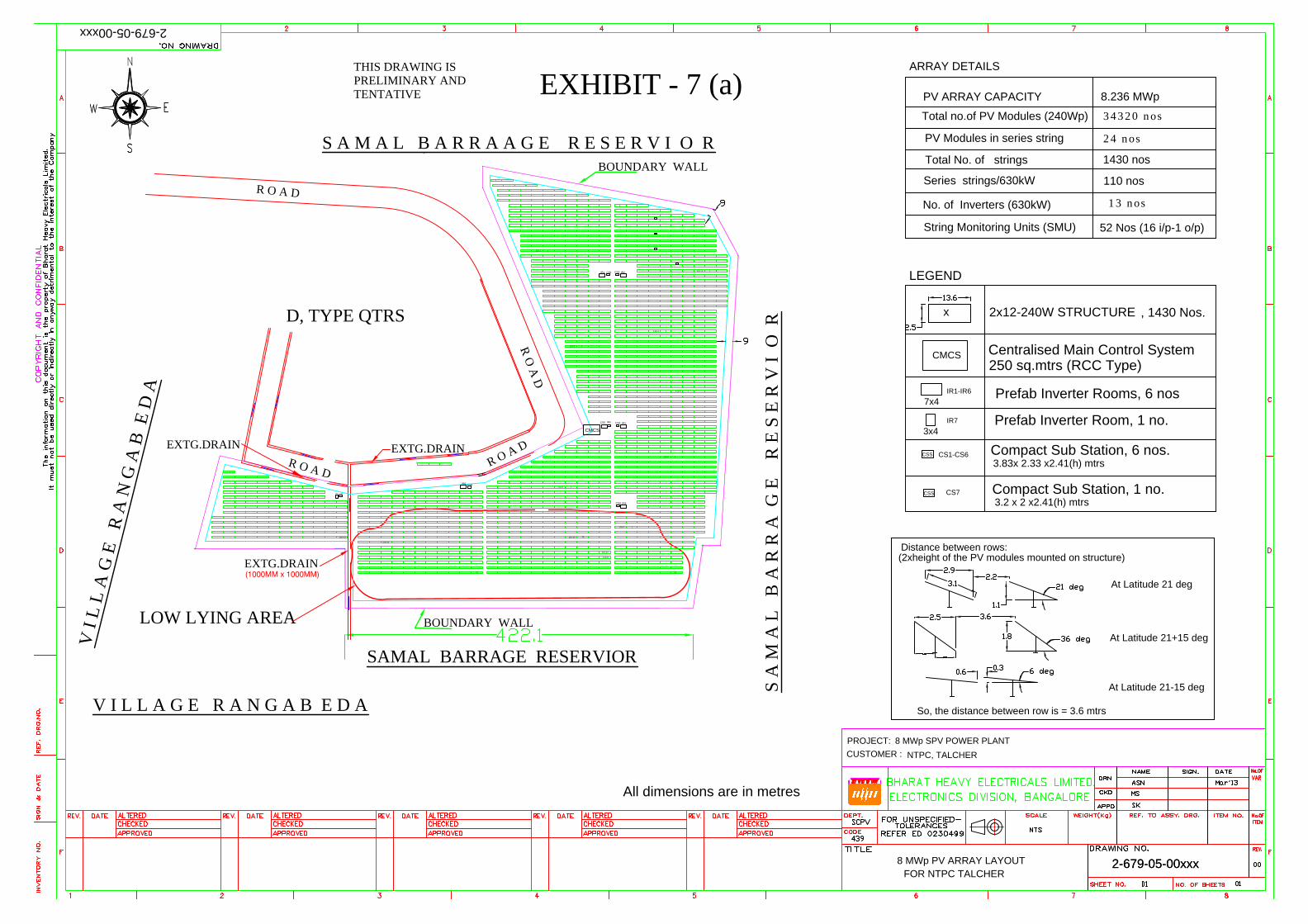
LOGO
SUPPLIERS NAME AND
ADDRESS: INDICATIVE FIELD QUALITY PLAN ANNEXURE- I
ITEM : CIVIL WORK
SUB-SYSTEM : GEOTECH INVI, FOUNDATIONS,
EXCAVATION & FILL, SITE LEVELLING, CONCRETE, ROAD,
BUILDING ETC.
QP NO. :
REV. NO .:
DATE :
PAGE :
1
0
Page 1 of 12
PROJECT:
PACKAGE:
CONTRACT NO.
MAIN CONTRACTOR
Sl. No Activity and operation Characteristics / instruments Class of
check Type of Check Quantum Of check Reference Document Acceptance
Norms Format of
Record Remarks
1 2 3 4 5 6 7 8 9 D* 10 1 GENERAL REQUIREMENTS A All bought out items to
be
procured from the approved
Contractor and on approval
of Quality plans by NTPC as
per inspection Category
-
B Verification of TC
and/or Testing 100%
NTPC Tech. Spec. /BOQ
SR/LB √ The TC submitted should bear proper
identification or correlation with the
batch of material supplied and same
shall be brought out in the challan/
consignment note . B Submission of list of Bought out
items and their Contractors
for each of the bought out
item identified for approval
within the period agreed in LoA.
-
A Physical One time
NTPC Tech. Spec. /BOQ
SR/LB To be submitted to CQA for approval with
a copy to site .
2 EXCAVATION AND FILLING IN FOUNDATION WORKS Excavations- 2.1 Nature, type of soil/rock before
and during excavations As agreed / required B Visual Random in eah shift Tech Specs and Const. Drawings SR
2.2 Initial ground level before start
of excavations As agreed / required B Measurement 100% Tech Specs and Const. Drawings SR √
2.3 Final shape and Dimensions
of excavations. As agreed / required B Measurement 100% Tech Specs and Const. Drawings SR
2.4 Final excavation lelvels As agreed / required B Measuement 100% Tech Specs and Const. Drawings SR √ 2.5 Side slope of final excavation As agreed / required B Measurement Random in eah shift Tech Specs and Const. Drawings SR 2.6 Excavation in Hard Rock- If required i Receipt, Storage, accountability
of
Explosive
As agreed / required B Physical Random in each week
Indian Explosive Act 1940/all statutory
norms, Tech Specs and Const. Drawings SR √ NTPC approved specialist blasting
agency such as CMRI, NIRM shall be
deployed at site for trial blasts, design
blasts, blast vibration monitoring etc.
Seismographs shall be deployed at site
for monitoring of blast operation
vibrations.
ii Execution of Blasting Operation As agreed / required B Physical Random in eah shift IS:4081, Tech Specs and
Const. Drawings SR √
iii Submission of Blasting report to EIC As agreed / required C Physical Each blast
Tech Specs and Const. Drawings √
2.7 Excavation in Hard Rock (Blasting
Prohibited)
As agreed / required B Physical 100% As per approved drawing/ scheme, Tech
Specs and Const. Drawings SR √
Fill/ Backfill - 2.8 A Suitability of borrow fill material - If earth is brought from area within the NTPC acquired area Suitability
As agreed / required B Visual Randon in each shift
As per technical specifications
2.8 B Suitability of borrow fill material- Applicable in case the earth is brought from an area, out of the NTPC aquired land area i Grain size analysis Set of Seives,
Hydrometer etc. B Physical Once per each type of
source or change of
source IS:2720 (Pt.IV), Tech Specs and
Const. Drawings SR/TR √
ii Liquid & plastic limit Mechanical liquid
limit device, grooving
tools, Evaporating
Disc,Spatula, Palette
knives, Balance oven
containers, etc.
B Physical Once per each type of
source or change of
source IS:2720 (Pt.IV) , Tech Specs and
Const. Drawings
SR/TR √
iii Shrinkage limit -do- B Physical Once per each type of
source or change of
source IS:2720 (Pt.IV), Tech Specs and
Const. Drawings SR/TR √
iv Free Swell Index Measuring cylinders,
etc. B Physical Once per each type of
source or change of
source IS:2720 (Pt.XI), Tech Specs and
Const. Drawings SR/TR √
v Chemical Analysis
Page 1 of 12
LOGO
SUPPLIERS NAME AND
ADDRESS: INDICATIVE FIELD QUALITY PLAN ANNEXURE- I
ITEM : CIVIL WORK
SUB-SYSTEM : GEOTECH INVI, FOUNDATIONS,
EXCAVATION & FILL, SITE LEVELLING, CONCRETE, ROAD,
BUILDING ETC.
QP NO. :
REV. NO .:
DATE :
PAGE :
1
0
Page 2 of 12
PROJECT:
PACKAGE:
CONTRACT NO.
MAIN CONTRACTOR
Sl. No Activity and operation Characteristics / instruments Class of
check Type of Check Quantum Of check Reference Document Acceptance
Norms Format of
Record Remarks
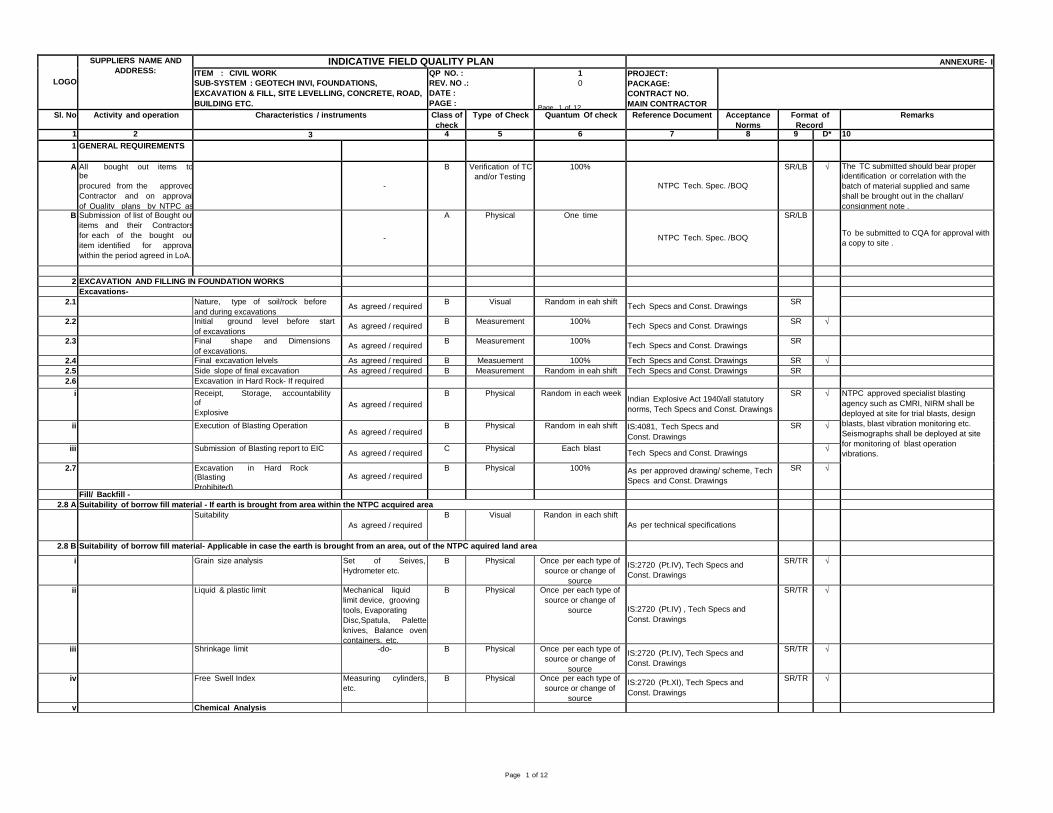
1 2 3 4 5 6 7 8 9 D* 10 a Organic Matter Oven chemical
balance, volumetric
flasks, burettes,
pipettes, conical flasks,
set of seives,
measuring cylinders
etc.
B Physical Once per each type of
source or change of
source
IS:2720 Pt.XXII, Tech Specs and Const.
Drawings
SR/TR √
b Calcium carbonate Reagents and
indicators,Burette,flask
s,funnels etc.
B Physical Once per each type of
source or change of
source Part XXIII of IS-2720, Tech Specs and
Const. Drawings SR/TR √
c pH value As agreed / required
B Physical Once per each type of
source or change of
source Part XXVI of IS-2720, Tech Specs and
Const. Drawings SR/TR √
d Total soluble sulphate As agreed / required
B Physical Once per each type of
source or change of
source Part XXVII of IS-2720, Tech Specs and
Const. Drawings SR/TR √
2.9 Standard proctor Test Optimum moisture content and max.
dry density before fill As per IS: 2720,
Proctor needle
apparatus,etc.
A Physical Once per each type of
source or change of
source IS 2720 (Pt.VII), Tech Specs and
Const. Drawings SR/TR √
2.10 Moisture content Moisture content of fill before
compaction As per IS:
2720, balance, oven
etc.
A Physical Once per each type of
source or change of
source IS 2720 (Pt.II), Tech Specs and
Const. Drawings SR/TR √
2.11 Degree Of Compaction Of Fill / Backfill i Dry density by core cutter method
---- OR----
Dry density in place by sand
displacement method
As per IS:
2720/compaction test
(core cutter), balance
etc.
A Physical i) For foundation fill/
backfill one for every
10 foundations for each
compacted layer.
IS 2720 (Pt. XXIX), Tech Specs and
Const. Drawings
SR/TR √
ii) For area filling, one
every 1000 SQM area
for each compacted
layer.
IS 2720 (Pt. XXVIII), Tech Specs and
Const. Drawings
SR/TR √
ii Relative density (Density Index) As per IS:
2720, balance oven etc. A Physical ----do----- (i) & (ii) above IS 2720 (Pt. XIV), Tech Specs and Const.
Drawings SR/TR √
iii Dry Density by proctor
needle penetration As per IS-2720,
proctor nedle apparatus
etc.
B Physical Random checks to
be carried out for
each compacted layer
Tech Specs and Const. Drawings
SR/TR √
3.0 MATERIALS Expert openion regarding suitability of construction materials shall be taken from Specialist Institute (Identified during pre award) 3.1 CEMENT Retesting of cement as per IS:4031 A Testing At Random As per relevant IS Codes Test
Report √ Each consignment of cement shall be duly
correlated with manufactureres TC,in case
the cement is supplied by the contractor
one sample from each lot shall be tested
for stetting time and compressive strength
. Acceptance norms shall be as per
relevant IS. If cement is
stored more than 60 days in godown of
contractor same shall be retested for
comp. Strength & setting time. 3.2 Coarse Aggregate Moisture content as per IS:2386 B Physical Once for each stack
of
100 Cu.M. or part
there of
IS : 456 IS
: 383/Tech Spec SR/LB √ during monsoon when this has to
be done every day before start of
concreting ii Specific gravity, water absorption IS:2386 A Physical Once for each source
& for every change of
source
IS: 2386 Part-III, IS:456,
IS:383/Tech Spec SR/LB/
Test
Report
√
iii Sieve analysis, flakiness index,
elongation index, IS:2386 B Physical One per 100 cum.,
or part thereof IS: 2386 Part-I, IS:383/Tech
Spec SR/LB √
iv Deleterious materials (coal & lignite, clay
lumps, material finer than 75 micron
sieve, soft fragment, shale)
IS:2386 A Physical Once per source/ on
every change of source IS: 2386 Part-II, IS:383/Tech
Spec SR/LB/
Test
Report
√
Page 2 of 12

LOGO
SUPPLIERS NAME AND
ADDRESS: INDICATIVE FIELD QUALITY PLAN ANNEXURE- I
ITEM : CIVIL WORK
SUB-SYSTEM : GEOTECH INVI, FOUNDATIONS,
EXCAVATION & FILL, SITE LEVELLING, CONCRETE, ROAD,
BUILDING ETC.
QP NO. :
REV. NO .:
DATE :
PAGE :
1
0
Page 3 of 12
PROJECT:
PACKAGE:
CONTRACT NO.
MAIN CONTRACTOR
Sl. No Activity and operation Characteristics / instruments Class of
check Type of Check Quantum Of check Reference Document Acceptance
Norms Format of
Record Remarks
1 2 3 4 5 6 7 8 9 D* 10 v Soundness IS:2386 A Physical -do- IS: 2386 Part-V, IS:383 SR/LB/
Test
Report
√
vi Crushing value abrasion value
and impact value IS:2386 A Physical -do- IS:383, IS-2386 Part IV/Tech Spec SR/LB/
Test
Report
√
3.3 Fine Aggregate i Moisture content, water absorption balance , oven etc B Physical To be done every
day before start of work IS: 2386 Part-III IS:383 SR/LB/TR √
ii Deleterious materials (coal & lignite, clay
lumps, material finer than 75 micron
sieve, soft fragment, shale)
IS:2386 B Physical Once per source& for
on every change of
source
IS: 2386 Part-II, IS:383 SR/LB/TR √
iii All other tests similar to
coarse aggregates as mentioned above. IS-2386, IS-383 SR/LB/TR √ except test for flankiness
index,elongation index, abrasion value,
impact value 3.4 Water i Complete tests as per IS:456 Buret, conical
flask, pipette etc B Testing One per 3 month
for each source. IS:3025 part 22 and 23 (for test procedure
), IS:456(for acceptance criteria ) SR/LB/TR √
3.5 CONCRETE i 4 Trial mixes to ascertain the
workability and cube strength After receiving the
recommended mix
design from specialist
agency,
A Physical One for each
mix proportion NTPC tech specification SR/LB √
ii Crushing strength (works Tests cubes) IS:516 A Physical IS 456-2000 IS:516, IS:456, NTPC Tech. Spec. SR/LB/
Test
Report
√ Min. of 6 cubes for each mix, 3 specimen
shall be tested at 7 days remaining 3 shall
be for 28 days comp. Strength.
iii Workability - slump test IS:1199 B Physical At the time of concrete
pouring at site every two
hrs
IS:456/NTPC Tech. Spec. SR/LB/TR √
iv Water content B Physical Once per shift As per approved design mix. SR/LB √ At batching plant 3.5.1 Admixtures for Concrete Type of admixture As per IS:9103 A
EIC Approved
source and review
of MTC/ test
reports
For each lot received
at site Designed mix and IS:9103 Test
Report √ Admixture of appd. Brand and tested
quality shall be used (each lot of
admixture will included with brochure in
which the type of admixture and its
properties shall be clearly indicated) Suitability As per IS:9103 B Physical For each lot received
at site Designed mix and IS:9103 SR/LB/T
R √ Relative density, pH and slump
retention on each batch / lot of admixture
and to compare these properties with
MTC 3.6 Concrete conveying,
placing& compaction
i mixing of concrete shall be done in
a approved mixer such as to produce
a homogenous mix To be calibrated at the
time of starting and
subsequently once in
three months, and shall
conform to IS:4925
Review of calibration chart/ Certificate, IS
4926 √
ii Arrangement for transportation &
placement of concrete.
As required C Visual 100% Before clearance for concreting Inspectio
n Report √
iii Calibration of Batching Plant batcher should
comply with
reqirement of IS
4926/IS:4925
A Physical To be calibrated at the
time of starting and
subsequently once in
three months, and shall
conform to IS:4925
Review of calibration chart/ Certificate Calibrati
on
Certificat
e
√ Provision of online printer is manadatory
iv Handling and Transportation of concrete As required B Physical 100% As per construction/erection methodology
(to be approved one week prior to start of
work)
SR
Page 3 of 12

LOGO
SUPPLIERS NAME AND
ADDRESS: INDICATIVE FIELD QUALITY PLAN ANNEXURE- I
ITEM : CIVIL WORK
SUB-SYSTEM : GEOTECH INVI, FOUNDATIONS,
EXCAVATION & FILL, SITE LEVELLING, CONCRETE, ROAD,
BUILDING ETC.
QP NO. :
REV. NO .:
DATE :
PAGE :
1
0
Page 4 of 12
PROJECT:
PACKAGE:
CONTRACT NO.
MAIN CONTRACTOR
Sl. No Activity and operation Characteristics / instruments Class of
check Type of Check Quantum Of check Reference Document Acceptance
Norms Format of
Record Remarks
1 2 3 4 5 6 7 8 9 D* 10 v Placement of concrete Visual B Physical 100% As per construction/erection
methodology and tech.specs / No
segregation
SR √
vi Placement Visual B Physical 100% As per approved
construction methodology SR √
vii Compacting As required B Physical At Random IS:456 SR √ viii Curing As required B Physical At Random Period of curing as per IS 456 (use
gunny bags / curing compound) SR √
3.7 TEST/CHECK ON RCC STRUCTURE IN HARDENDED CONDITIONS i Visual inspection of concrete surface
of all dynamic foundations just
after removal of shuttering
As required A Visual 100% As per Technical Specification
SR √
ii Embeddment of inserts in concrete shall
be checked for gap if any using hammer
for all dynamic foundations
Hammer A Visual 100% As per Technical Specification
SR √ No hollow sound
iii Dimensional check on finished structures
& Dimensional tolerances As required B Measurement Approved Drawing As per IS:456/ tech. Specification. SR/LB √
iv Water Tightness Test of liquid
retaining structure/ tanks As required A Test 100% IS:3370/ Tech. Specification SR/LB √
3.8 REINFORCEMENT STEEL i Physical and Chemical Properties
for each lot as per relevant IS codes As required/ agreed A EIC Approved
source and review
of MTC/ test
reports
Each batch of delivery IS : 1786, IS:432, IS:1566, Tech
Specs and Const. Drawings
MTC √
Applicable if steel is procured by
Contractor
ii Freedom from cracks surface
flaws, Lamination. As agreed / required
B Visual Random in each shift IS: 1852, IS:432, IS:1786, Tech
Specs and Const. Drawings
SR To be checked at site. Steel collected
from source should be free from excessive
rust. To be stored as per Technical
Specs. 3.9 PLACEMENT OF REINFORCEMENT STEEL i Bar bending schedule with
necessary lap, Spacers & Chairs
As agreed / required B Visual &
Measurement Random in each shift Approved Drawings, Tech Specs and
Const. Drawings, IS:2502 SR
√ ii Bending of bars, cutting tolerance
As agreed / required B Visual &
Measurement Random in each shift Approved Drawings, Tech Specs and
Const. Drawings, IS:2502 SR
√ iii Acceptance - Cover, spacing of
bars, spacers and chairs
after the reinforcement
cage is put inside the formwork
As agreed / required
B Visual &
Measurement Random in each shift
Approved Drawings, Tech Specs and
Const. Drawings
SR √
3.10 STAGING AND FORMS i Materials and accessories As agreed / required
B Visual Once before start
of work As per relevant IS, Tech Specs and
Const. Drawings SR
ii Soundness of staging, shuttering and
scaffolding including application of
mould oil / release agent
As agreed / required B Visual Once before start
of work As per manufacturer's spec.and as per
3696,4014, 4990, Tech Specs and Const.
Drawings
SR
iii Acceptance of formwork before start of
concreting B Physical / visual Before start of
each
concreting As per provisions and tolerances, Tech
Specs and Const. Drawings SR
√
3.11 INSPECTION OF CONCRETE SURFACE JUST AFTER REMOVAL OF FORM WORK i Visual inspection jointly with
NTPC Concrete surface, position and
alignment of embedded parts and inserts -- B Visual Once for TG, BFP &
MILL foundations As per provisions and tolerances of
equipment supplier, Tech Specs and
Const. Drawings
√ Inspection protocol shall be signed
Jointly by Contractor and NTPC CCD &
Erection ii Submission of grouting /
repair methodology if concrete
surface / position and
alignment of embedded parts /
inserts are found defective
-- B Review and
approval once for each type of
defect
As per provisions and tolerances, Tech
Specs and Const. Drawings
√
Page 4 of 12

LOGO
SUPPLIERS NAME AND
ADDRESS: INDICATIVE FIELD QUALITY PLAN ANNEXURE- I
ITEM : CIVIL WORK
SUB-SYSTEM : GEOTECH INVI, FOUNDATIONS,
EXCAVATION & FILL, SITE LEVELLING, CONCRETE, ROAD,
BUILDING ETC.
QP NO. :
REV. NO .:
DATE :
PAGE :
1
0
Page 5 of 12
PROJECT:
PACKAGE:
CONTRACT NO.
MAIN CONTRACTOR
Sl. No Activity and operation Characteristics / instruments Class of
check Type of Check Quantum Of check Reference Document Acceptance
Norms Format of
Record Remarks
1 2 3 4 5 6 7 8 9 D* 10 3.12 EMBEDDED PART(INCLUDING LAYING OF RAILS & ANCHOR FASTENERS)
i Position / alignment / levels of
embedded parts / bolt hole / pipe
sleeves / rails / PVC pipes / etc
As agreed / required B Physical/
measurement 100%
As per drawing, Tech Specs and
Const. Drawings
SR/
Protocol √
Exposed surfsce of the embeded parts
other than holding down bolts are to be
painted with as per technical
specifications ii Welding / tieing of embeddment
to reinforce-ment As agreed / required B Physical/
measurement Random in each shift As per drawing, Tech Specs and
Const. Drawings SR
3.13 PRE-CAST CONCRETE i Crushing strength compression strength
testing machine A Physical one sample of six
cubes per 50m m3 or
part thereof
IS:516 & IS: 456 SR/LB √
A minimum of three specimen shall
be tested for 7 and 28 days
compressive strength ii Workmanship and dimentions Visual B Physical 100% As per IS:456/NTPC Tech. specification. Register
iii Load Test As required B Physical 1% up to 1000 nos. and
0.5% for more than
1000 nos. for each type
IS:456/ As decided by NTPC Site
Engr. Incharge. Inspectio
n Report
√
3.14 JOINTS IN CONCRETE i Joint material - bitumen
impregnated fibre board, PVC water
stops, Sealing compound, Expanded
polystyrene board, Hydrophillic strip,
Acrylic polymer etc.
As per manufacturer
Standards
A EIC Approved
source and review
of MTC/ test
reports
Each batch of delivery Tech Specs and Const. Drawings, IS
1838, IS 1834, IS12200 MTC
√
ii Acceptance of installation As agreed / required B Acceptance Each installation
randomly Tech Specs and Const. Drawings 3.15 DAMP PROOF COURSE Tech Specs and Const. Drawings
i
Material - Hot bitumen and water
proofing materials etc
As agreed / required
A EIC Approved
source and review
of MTC/ test
reports
Each batch of delivery
at site Tech Specs and Const. Drawings, IS 702
SR
√
ii Acceptance of damp proof course As agreed / required B Acceptance 100% Tech Specs and Const. Drawings SR 3.16 GROUTING i Material As agreed / required
A EIC Approved
source and review
of MTC/ test
reports
Each batch of delivery Tech Specs and Const. Drawings
SR
√
Type of mix - fluid mix, plastic mix,
stiff mix etc.
As agreed / required B Physical Prior to start of work
Tech Specs and Const. Drawings
SR
√
ii Mixing, placement, application and
grout pressure As agreed / required B Physical Random in each shift Tech Specs and Const. Drawings SR
iii Compressive strength As agreed / required A Physical Random in each shift
Tech Specs and Const. Drawings SR √ iv Acceptance of the grouts As agreed / required B Physical Each grout section Tech Specs and Const. Drawings SR
4.00 BRICK MASONARY 4.1 Test on Bricks Dimensions , shape, compressive
strength, water absorption, warpage,
efflorescence.
As agreed / required A Measurement/
Physical Test As per relevant IS
Code/ One Sample for
30,000 nos. or part
thereof
IS: 1077, IS:13757, IS: 12894 / Tech
Specs and const. Drawings
Inspectio
n Report √
Efflorescence shall be checked at
each source.
4.2 Test on Mortar i Compressive strength As agreed / required B Test At random IS 2250-1981, Tech Specs and
Const. Drawings LB
ii Sand Grading As agreed / required B Test IS:2116 SR/LB 4.3 Masonry construction Workmanship, verticality and alignment
As agreed / required B Visual/ Physical 100% IS 2212, IS 1905 , Tech Specs and
Const. Drawings SR/LB
5.00 FINISHING AND ALLIED WORKS . 5.1 PLASTERING- MATERIAL
Page 5 of 12

LOGO
SUPPLIERS NAME AND
ADDRESS: INDICATIVE FIELD QUALITY PLAN ANNEXURE- I
ITEM : CIVIL WORK
SUB-SYSTEM : GEOTECH INVI, FOUNDATIONS,
EXCAVATION & FILL, SITE LEVELLING, CONCRETE, ROAD,
BUILDING ETC.
QP NO. :
REV. NO .:
DATE :
PAGE :
1
0
Page 6 of 12
PROJECT:
PACKAGE:
CONTRACT NO.
MAIN CONTRACTOR
Sl. No Activity and operation Characteristics / instruments Class of
check Type of Check Quantum Of check Reference Document Acceptance
Norms Format of
Record Remarks
1 2 3 4 5 6 7 8 9 D* 10 i Sand Deleterious Material
As agreed / required B Physical Once per source IS : 2386 (Part-I &II) & IS :2116, Tech
Specs and Const. Drawings SR
ii Grading As agreed / required
B Physical 50 Cum./or part thereof Tech Specs and Const. Drawings SR
iii Galvanised wire mesh Galvanized hexagonal wire netting for
lath plastering As agreed / required
B EIC Approved
source and review
of MTC/ test
reports
Each batch of delivery Tech Specs and Const. Drawings
SR
5.2 PLASTERING - WORKMANSHIP i
Curing
As agreed / required
C
Physical
100% Tech specifications, construction
drawings and agreed methodology
SR
ii Thickness and finishing of
plaster, grooves etc As agreed / required B Visual/
Measurement Random in each shift
Tech Specs and Const. Drawings SR/LB iii Truness of plastering system As agreed / required B Visual/ Physical Random in each shift Tech Specs and Const. Drawings SR 5.3 STONE GRIT PLASTER/ GRANULAR TEXTURED COAT FINISH i
Material
As agreed / required
B Approved source
and review of
MTC
For each lot received at
site
Tech Specs and Const. Drawings
SR
√
ii Thickness, finishing and grooves etc As agreed / required B Visual/
Measurement
Random in each shift Tech Specs and Const. Drawings SR √ 6.00 SHEETING AND OTHER WORKS 6.1 PAINTING SYSTEM - CONCRETE WORKS AND PLASTERED MASONARY SURFACES
i Materials and accessories-
Oil Bound, Acrylic Emulsion,
Chemical Resistant, Oil
Resistant Paint etc.
Shade, type from brand and
manufacturer as approved by NTPC EIC
As agreed / required A EIC Approved
source and review
of MTC/ test
reports
Each batch of delivery Tech Specs and Const. Drawings
SR/MTC √
ii Surface prepration As required As agreed / required C Physical /visual Random in each shift Tech Specs and Const. Drawings SR iii Acceptance of painted surfaces As required
As agreed / required B Physical Each surface at random Tech Specs and Const. Drawings SR
6.1.1 PAINTING SYSTEM - STEEL WORKS (OTHER THAN STRUCTURAL STEEL WORKS) i Paining Materials and accessories - A EIC Approved
source and review
of MTC/ test
reports
Each batch of delivery Tech Specs and Const. Drawings SR/MTC √
Mfr.’s T.C. shall be correlated with
the consignment received.
ii Submission of painting methodology - B For Review of
painting system Before start of
painting work Tech Specs and Const. Drawings
iii Surface prepration As agreed / required B Physical /visual Each Erection Mark Tech Specs and Const. Drawings,
Relevant code/ standards SR
√ iv Primer Thickness Elcometer B Measurement Each Erection Mark Tech Specs and Const. Drawings SR √ v DFT of paint Elcometer B Measurement Each Erection Mark Tech Specs and Const. Drawings SR √
vi Acceptance of painted surfaces Elcometer B Visual and
measurement Each Erection Mark Tech Specs and Const. Drawings SR
7.00 DOORS , WINDOWS VENTILATORS & GRILL 7.1 Steel doors i Materials (MS sheet, fasteners, hinges,
jambs, lock strike plate etc As agreed / required A Visual/ Physical /
test report For each lot received at
site Tech Specs and Const. Drawings SR / LB √ Review of test report
ii Flush Door shutters, teak beading As agreed / required
A EIC Approved
source and review
of MTC/ test
reports
For each lot received at
site IS 2202, Tech Specs and Const.
Drawings
SR √
Review of test report
iii Hollow metal doors (material
and dimensions)
As agreed / required A Visual/
Physical/Test
report
For each lot received at
site Tech Specs and Const. Drawings
√ Review of test report
iv Acceptance As agreed / required B Visual/ Physical Random Tech Specs and Const. Drawings SR/LB 7.2 Anodised aluminium works
Page 6 of 12

LOGO
SUPPLIERS NAME AND
ADDRESS: INDICATIVE FIELD QUALITY PLAN ANNEXURE- I
ITEM : CIVIL WORK
SUB-SYSTEM : GEOTECH INVI, FOUNDATIONS,
EXCAVATION & FILL, SITE LEVELLING, CONCRETE, ROAD,
BUILDING ETC.
QP NO. :
REV. NO .:
DATE :
PAGE :
1
0
Page 7 of 12
PROJECT:
PACKAGE:
CONTRACT NO.
MAIN CONTRACTOR
Sl. No Activity and operation Characteristics / instruments Class of
check Type of Check Quantum Of check Reference Document Acceptance
Norms Format of
Record Remarks
1 2 3 4 5 6 7 8 9 D* 10 i Materials- Aluminium sections,
alkali resistant paint
As agreed / required A Visual/ Physical /
test report For each lot received at
site IS: 1948, IS: 1949, IS:733, IS1285,
IS:1868, IS:11857/ Tech Specs and
Const. Drawings
SR / LB √
Review of test report
For aluminium door/windows, check
for anodisation as per Tech. Spec ii Particle Door
As agreed / required A EIC Approved
source and review
of MTC/ test
reports
For each lot received at
site IS:12823 (phenol formaldehyde sythentic
resin, BWP type), Tech Specs and Const.
Drawings
SR √
Review of test report
iii Acceptance As agreed / required B Visual/ Physical Random Tech Specs and Const. Drawings SR 7.3 Fire proof doors i Source of supply
As agreed / required
A Review of
purchase order
(unpriced copy) /
drawings of
suppliers /
certificate of CBRI
For each source
Tech Specs and Const. Drawings
SR
√
Procured from Approved parties as per
relevant IS/Tech, The
door drawing proposed for supply should
have been tested and approved by CBRI
Roorkee for the similar dimensions for
minimum 2 hours fire rating.
ii Receipt inspection As agreed / required A Visual/ Physical/
Review of MTC For each lot received at
site Tech Specs and Const. Drawings SR √
iii Finishing and acceptance As agreed / required B Visual / physical Random Tech Specs and Const. Drawings SR 7.4 Rolling shutters i Surface finish and thickness of plate of
approved make and DFT As agreed / required A Physical / visual /
review of MTC Random for each lot of
delivery Tech Specs and Const. Drawings SR √ ii Finishing and acceptance As agreed / required B Physical and
acceptance Random Tech Specs and Const. Drawings SR 7.5 Steel windows / Grills/ Louvre
i Material fabrication and fixtures
As agreed / required
A
EIC Approved
source and review
of MTC/ test
reports
Each lot of delivery
IS: 1038 / IS:1361, IS: 7452 and Tech
Specs and Const. Drawings
SR
√
ii Finishing and acceptance
As agreed / required
B
Visual / physical Random
IS: 1038 / IS:1361, IS: 7452 and Tech
Specs and Const. Drawings SR
√
7.6 Glass and glazing i
Clear float glass, wired
glass, tinted glass, curtain
glass, hermetically sealed
glass
Material As agreed / required
B EIC Approved
source and review
of MTC/ test
reports
For each lot received at
site IS: 14900, IS:1081, IS: 3548, IS:5437
Tech Specs and Const. Drawings
SR √
ii Installation finishing and acceptance As agreed / required B Visual/ Physical Random
Tech Specs and Const. Drawings SR Leak proof installation with neoprene
gasket 7.7 Curved dome on roof/ Poly Carbonate Sheet
i Source of supply Impact strength, K value, light
transmission value with class -I fire
rating
As agreed / required
A EIC Approved
source and review
of MTC/ test
reports
For each lot received at
site Tech Specs and Const. Drawings
SR √
ii Installation finishing and acceptance As agreed / required B Visual / physical Random Tech Specs and Const. Drawings SR
7.8 Reflective toughened glass i Material
As agreed / required A EIC Approved
source and review
of MTC/ test
reports
For each lot received at
site Tech Specs and Const. Drawings
SR √
ii Installation finishing and acceptance As agreed / required B Visual / physical Random Tech Specs and Const. Drawings SR
7.9 False Ceiling i Materials ( gypsum glass, glass fibre
membrane, fibre board acoustical tiles
etc) As agreed / required
A EIC Approved
source and review
of MTC/ test
reports
For each lot received at
site Tech Specs and Const. Drawings
SR √
Compare MTC with technical
specification and requirement
ii Installation finishing and acceptance As agreed / required B Visual / physical Random Tech Specs and Const. Drawings SR Page 7 of 12

LOGO
SUPPLIERS NAME AND
ADDRESS: INDICATIVE FIELD QUALITY PLAN ANNEXURE- I
ITEM : CIVIL WORK
SUB-SYSTEM : GEOTECH INVI, FOUNDATIONS,
EXCAVATION & FILL, SITE LEVELLING, CONCRETE, ROAD,
BUILDING ETC.
QP NO. :
REV. NO .:
DATE :
PAGE :
1
0
Page 8 of 12
PROJECT:
PACKAGE:
CONTRACT NO.
MAIN CONTRACTOR
Sl. No Activity and operation Characteristics / instruments Class of
check Type of Check Quantum Of check Reference Document Acceptance
Norms Format of
Record Remarks
1 2 3 4 5 6 7 8 9 D* 10 7.10 WATER PROOFING
Methodology for the application of water
proofing system As required B Review for each type of
treatment Tech Specs and Const. Drawings SR √
7.10.1 General Requirement- Water Proofing
i
Polyurethene based coating,
polyester scrim cloth, extruded
HD dimpled polyurethene
Material
As agreed / required
A
EIC Approved
source and review
of MTC/ test
reports
For each lot received at
site Tech Specs /Const. Drawings
SR
√
MTC shall contain all the parameters
specified in the technical specifications
ii Acceptance of water proofing work As agreed / required B Physical 100% Tech Specs and Const. Drawings 7.10.2 Roof / Basement Treatment i Graded under bed Levels / slopes As required C Physical 100% Tech Specs and Const. Drawings
ii Elastomaric coatings
Material- Primer coat, finishing coat
As required
B
EIC Approved
source and review
of MTC/ test
reports
Each lot of delivery
Tech Specs and Const. Drawings
SR
√
iii Wearing course Materials - PCC, chicken wire mesh,
elastomeric sealant As required B Review of MTC Each lot of delivery Tech Specs and Const. Drawings SR √ iv Acceptance of water proofing work As agreed / required B Physical 100% Tech Specs and Const. Drawings 7.11 Fencing and Gates
i
PVC coated chain link
fencing (IS 2720), Welded
wire mesh (IS 1566),
Reinforced barbed tape
galvanised (IS 2629) etc.
Materials
As agreed / required
A EIC Approved
source and review
of MTC/ test
reports
Each batch of delivery Tech Specs and Const. Drawings
SR/MTC
√ MTC shall contain all the parameters
specified in the technical specifications
ii
Structural steel, painting
system, caster wheel, ball and
bearing, fixtures and fasteners Materials
As agreed / required
A EIC Approved
source and review
of MTC/ test
reports
Each batch of delivery Tech Specs and Const. Drawings
SR/MTC √
MTC shall contain all the parameters
specified in the technical specifications
iii Alignments, erection painting, DFT etc. As agreed / required B Physical /
measurements Each installation
Tech Specs and Const. Drawings SR iv Acceptance of the installation
and working As agreed / required B Physical /
measurements Each installation
Tech Specs and Const. Drawings SR 7.12
FLOOR FINISHES AND ALIED WORKS
7.12.1 Cement Concrete Flooring i Glass/ PVC strips in joints As agreed / required B Physical Random in each shift Tech Specs and Const. Drawings SR ii Finishing and acceptance As agreed / required B Physical 100% Tech Specs and Const. Drawings SR
7.12.2 Tiles
i
Ceramic, vitrified, glass
mosaic, acid alkali resistant,
heavy duty cement concrete
tiles
Materials
As agreed / required
A
EIC Approved
source and review
of MTC/ test
reports
Each lot of delivery
Tech Specs and Const. Drawings
SR
√
MTC shall contain all the parameters
specified in the technical specifications
ii Finishing and acceptance As agreed / required B Physical 100% Tech Specs and Const. Drawings SR 7.12.3 Interlocking Blocks
i
Materials
As agreed / required
A EIC Approved
source and review
of MTC/ test
reports
Each lot of delivery
Tech Specs and Const. Drawings
SR
√
MTC shall contain all the parameters
specified in the technical specifications
ii Finishing and acceptance As agreed / required B Physical 100% Tech Specs and Const. Drawings SR 7.12.4 Kota Stone, Granite and Marble
i
Quality, texture, thickness, colour for
each lot of delivery from approved
source
As agreed / required
B
Physical
Each batch of delivery
Tech Specs and Const. Drawings
SR
√
ii Finishing and acceptance As agreed / required B Physical 100% Tech Specs and Const. Drawings SR 7.12.5 Metallic / non-metallic hardener
i Material As agreed / required B Physical Each batch of delivery Tech Specs and Const. Drawings SR √ Page 8 of 12

LOGO
SUPPLIERS NAME AND
ADDRESS: INDICATIVE FIELD QUALITY PLAN ANNEXURE- I
ITEM : CIVIL WORK
SUB-SYSTEM : GEOTECH INVI, FOUNDATIONS,
EXCAVATION & FILL, SITE LEVELLING, CONCRETE, ROAD,
BUILDING ETC.
QP NO. :
REV. NO .:
DATE :
PAGE :
1
0
Page 9 of 12
PROJECT:
PACKAGE:
CONTRACT NO.
MAIN CONTRACTOR
Sl. No Activity and operation Characteristics / instruments Class of
check Type of Check Quantum Of check Reference Document Acceptance
Norms Format of
Record Remarks
1 2 3 4 5 6 7 8 9 D* 10 ii Finishing and acceptance As agreed / required B Physical 100% Tech Specs and Const. Drawings SR
7.12.6 Acid / alkali and oil resistant high built seamless epoxy based resin and treatment
i Material
Bricks, vitreous tiles, mortar,
sealing, paints, coatings, sheets, fillers
etc
As agreed / required
A EIC Approved
source and review
of MTC/ test
reports
Each batch of delivery
Tech Specs and Const. Drawings
SR
√
Experienced workers under supervisors
recommended/ appointed by manufacturer
to be deployed ii Surface preparation As agreed / required B Physical Random in each shift Tech Specs and Const. Drawings, IS iii Finishing and acceptance As agreed / required B Physical 100% Tech Specs and Const. Drawings SR 7.13
Doors/Windows Sections i
Material - Rolled Steel,
Z Sections,T-iron frames
sections, Plates etc.
Review of MTC/ make / Physical
checks, tests ( if MTC is not available)
As agreed / required
A EIC Approved
source and review
of MTC/ test
reports
For each batch of
delivery Tech Specs and Const. Drawings
SR
√
ii Acceptance of Steel Glazed doors and T-
iron frames sections after fixing As agreed / required B Physical and
acceptance Random for each
installation Tech Specs and Const. Drawings SR
8.0 WATER SUPPLY / SANITORY INSTALLATIONS 8.1 Water supply fittings and fixtures
i Materials
GI/ MS pipes and fittings
As agreed / required
A
EIC Approved
source and review
of MTC/ test
reports
Each lot of delivery as
per Specifications Tech Specs and Const. Drawings
SR
√
ii Disinfection Before use As agreed / required B Physical Each installation Tech Specs and Const. Drawings SR iii Hydraulic test Before use / leakage As agreed / required A Physical Each installation Tech specs and const drawings SR √ iv Acceptance and working As agreed / required B Acceptance Random Tech Specs and Const. Drawings SR 8.2 Sand cast iron / cast iron pipes
i
Material SCI / CI pipes and fittings / joints
As agreed / required
A
EIC Approved
source and review
of MTC/ test
reports
Each lot of delivery as
per Specifications Tech Specs and Const. Drawings
SR
√
ii Acceptance and leakage As agreed / required B Physical Random Tech Specs and Const. Drawings SR
8.3 Sanitary fittings and fixtures
i
Material
Sanitory items and fixtures i.e. water
closets, urinals, wash basins, sinks,
mirrors, shelves, towel rail, soap
containers, geyser, water cooler, etc,
water supply / sanitation pipes, manhole
cover and frames etc
As agreed / required
B
EIC Approved
source and review
of MTC/ test
reports
Each lot of delivery as
per Specifications
Tech Specs and Const. Drawings
SR
√
ii Acceptance of installations of all sanitory
items and fixtures As agreed / required B Acceptance 100% Tech Specs and Const. Drawings SR
8.4 RCC Pipes
i
Material RCC pipes
As agreed / required
A
EIC Approved
source and review
of MTC/ test
reports
Each lot of delivery as
per Specifications Tech Specs and Const. Drawings /IS 458
SR
√
ii Acceptance and leakage As agreed / required B Physical Random Tech Specs and Const. Drawings SR 8.5 Water Storage Tanks
i
Material Over head / loft type
As agreed / required
A
EIC Approved
source and review
of MTC/ test
reports
Each lot of delivery as
per Specifications Tech Specs and Const. Drawings
SR
√
ii Aceptance and leakage As agreed / required B Acceptance Random Tech Specs and Const. Drawings SR 9.0 ROAD WORKS
Page 9 of 12

LOGO
SUPPLIERS NAME AND
ADDRESS: INDICATIVE FIELD QUALITY PLAN ANNEXURE- I
ITEM : CIVIL WORK
SUB-SYSTEM : GEOTECH INVI, FOUNDATIONS,
EXCAVATION & FILL, SITE LEVELLING, CONCRETE, ROAD,
BUILDING ETC.
QP NO. :
REV. NO .:
DATE :
PAGE :
1
0
Page 10 of 12
PROJECT:
PACKAGE:
CONTRACT NO.
MAIN CONTRACTOR
Sl. No Activity and operation Characteristics / instruments Class of
check Type of Check Quantum Of check Reference Document Acceptance
Norms Format of
Record Remarks
1 2 3 4 5 6 7 8 9 D* 10 9.1
Construction of Sub-Grade and earthen/hard soulders i Standard proctor Test
As per IS: 2720 A Physical One in every 2000 cum
for each type and source
of fill materials
As per Tech Specs and Const.
Drawings,Section 900 of MOSRTH
specification, IS 2720 (Pt.VII)
SR/TR √ In cutting or existing levelled ground -
quantum of check shall be one per 1000
SQM ii Moisture content of fill before
compaction
As per IS: 2720 B Physical One in every 2000 cum
for each type and source
of fill materials
As per Tech Specs and Const. Drawings,
Section 900 of MOSRTH specification, IS
2720 (Pt.II)
SR/TR In cutting or existing levelled ground -
quantum of check shall be one per 1000
SQM iii Dry density by core cutter method
---- OR----
Dry density in place by
sand displacement method
As per IS: 2720
A Physical One in every 500 SQM
area for each compacted
layer. As per Tech Specs and Const.
Drawings, Section 900 of MOSRTH
specification, IS
2720 (Pt. XXIX)/ IS 2720 (Pt. XXVIII),
SR/TR √ Both for embankment and cut formation
quantum of check - One in every 1000
SQM area for each compacted layer.
iv Lines, grade and cross section As required / agreed B Physical One in every 500 SQM
area As per Tech Specs and Const. Drawings SR Template, straight edge 9.2
Water Bound Macadam (Non-Bituminous) for base course and sub-base course i Aggregate Impact value Agrregate Impact value
Test Apparatus A Physical One test per 200 cum of
Test aggregate As perTech Specs and Const. Drawings,
Section 900 of MOSRTH specification, SR √
ii Grading Set of IS Sieves B Physical One test per 100 cum
of aggregate As perTech Specs and Const. Drawings,
Section 900 of MOSRTH specification, SR
iii Flakiness index and elongation index Flakiness test gauge B Physical One test per 200cun of
agregate As perTech Specs and Const. Drawings,
Section 900 of MOSRTH specification, SR
iv Atterberg Limits of binding material Atterberg limits
determination A Physical One test per 25 cum
of binding material As perTech Specs and Const. Drawings,
Section 900 of MOSRTH specification, SR √
v Atterberg Limits of portion of
agreggate passing 425 micron sieve Atterberg limits
determination A Physical One test per 100cum
of aggregate As perTech Specs and Const. Drawings,
Section 900 of MOSRTH specification, SR √
vi Camber, surface, slope As required / agreed B Physical One in every 500 SQM
area As per Tech Specs and Const. Drawings SR Template, straight edge 9.3 Bituminous Macadam for base and binder course
i Quality of binder Penetrometre with St.
needle
A Physical No. of samples per Lot &
tests as per IS:73,
IS:217, IS:8887 as
applicable
As per Tech Specs and Const.
Drawings, Section 900 of MOSRTH
specification, IS
73
SR √
ii Aggregate Impact Value / Los
angeles abrasion value Aggregate Impact
ValueTest apparatus A Physical Once per source As per Tech Specs and Const. Drawings,
Section 900 of MOSRTH specification SR √
iii Flakiness Index and elongation index
of aggregates Flakiness test gauge B Physical One test per 50 cum
of aggregate As per Tech Specs and Const. Drawings,
Section 900 of MOSRTH specification SR
iv Stripping value of aggregate
(Immersion tray test) As required / agreed
B Physical Initialy one set of 3
representative specimen
per source, and on every
change of source.
As per Tech Specs and Const.
Drawings, Section 900 of MOSRTH
specification
SR
v Water sensitivity of mix As required / agreed
A Physical Initialy one set of 3
representative specimen
per source, and on every
change of source.
As per Tech Specs and Const. Drawings,
Section 900 of MOSRTH specification
SR √
vi Grading of aggregates Set of Sieves
B Physical Two test per day per
plant both on individual
constituents and mixed
aggregate from dryer
As per Tech Specs and Const. Drawings,
Section 900 of MOSRTH specification
SR
vii Water absorption of aggregate As required / agreed
Initially one set of 3
representative specimen
per source, and on every
change of source.
As per Tech Specs and Const. Drawings,
Section 900 of MOSRTH specification
SR
viii Soundness ( Magnesium and Sodium
Sulphate)
As required as per
IS:2386
A Physical Once per source by
each method and on
every change of source
As per Tech Specs and Const.
Drawings, Section 900 of MOSRTH
specification
SR √
ix Percentage of fractured faces As required / agreed
B Physical When gravel is used
one test per 50cum of
aggregates As per Tech Specs and Const.
Drawings, Section 900 of MOSRTH
specification
SR
Page 10 of 12

LOGO
SUPPLIERS NAME AND
ADDRESS: INDICATIVE FIELD QUALITY PLAN ANNEXURE- I
ITEM : CIVIL WORK
SUB-SYSTEM : GEOTECH INVI, FOUNDATIONS,
EXCAVATION & FILL, SITE LEVELLING, CONCRETE, ROAD,
BUILDING ETC.
QP NO. :
REV. NO .:
DATE :
PAGE :
1
0
Page 11 of 12
PROJECT:
PACKAGE:
CONTRACT NO.
MAIN CONTRACTOR
Sl. No Activity and operation Characteristics / instruments Class of
check Type of Check Quantum Of check Reference Document Acceptance
Norms Format of
Record Remarks
1 2 3 4 5 6 7 8 9 D* 10 x Binder content and aggregate grading
Bitumen extractor A Physical Periodic, subject to a
min of two tests per day
per plant As per Tech Specs and Const.
Drawings, Section 900 of MOSRTH
specification
SR √
xi Control of Temperature of binder
and aggregate for mixing and of the
mix at the time of laying and rolling
Thermometer
B Physical At regular close intervals As per Tech Specs and Const.
Drawings, Section 900 of MOSRTH
specification
SR
xii Rate of spread of mixed materials As required / agreed
B Physical Regular control through
checks of layer thickness As per Tech Specs and Const.
Drawings, Section 900 of MOSRTH
specification
SR
xiii Density of compacted Layer As required / agreed
A Physical One test per 250 sqm of
area As per Tech Specs and Const. Drawings,
Section 900 of MOSRTH specification SR √
9.4 Bituminous Surfacing - Open graded premix carpet and Seal coat i Quality of binder Penetrometre with St.
needle A Physical No. of samples per Lot
& tests as per IS:73,
IS:217, IS:8887 as IS 73,Tech Specs and Const.
Drawings, Section 900 of MOSRTH
specification
SR √
ii Aggregate Impact Value / Los
angeles abrasion value Aggregate Impact
ValueTest apparatus A Physical One test per 50 cum
of aggregate As per Tech Specs and Const. Drawings,
Section 900 of MOSRTH specification SR √
iii Flakiness Index and elongation
indexof aggregates
Flakiness test gauge B Physical One test per 50 cum
of aggregate As per Tech Specs and Const.
Drawings, Section 900 of MOSRTH
specification
SR
iv Stripping value of aggregate
(Immersion tray test) As required / agreed
B Physical Initialy one set of 3
representative specimen
per source, and on every
change of source.
As per Tech Specs and Const. Drawings,
Section 900 of MOSRTH specification
SR
v Water absorption test A Physical Initialy one set of 3
representative specimen
per source, and on every
change of source.
As per Tech Specs and Const. Drawings,
Section 900 of MOSRTH specification
SR √
vi Water sensitivity of mix As required / agreed
A Physical Initialy one set of 3
representative specimen
per source, and on every
change of source.
As per Tech Specs and Const. Drawings,
Section 900 of MOSRTH specification
SR √
vii Grading of aggregates Set of Sieves B Physical One test per 25 cum
of aggregates As per Tech Specs and Const. Drawings,
Section 900 of MOSRTH specification SR
viii Soundness ( Magnesium and Sodium
Sulphate)
As required as per
IS:2386
A Physical Once per source by
each method and on
every change of source
As per Tech Specs and Const.
Drawings, Section 900 of MOSRTH
specification
SR √
ix Polished stone value As required as per
BS:812(Part 114) B Physical As required As per Tech Specs and Const. Drawings,
Section 900 of MOSRTH specification SR
x Temperature of binder at application Thermometer B Physical At regular close intervals As per Tech Specs and Const. Drawings,
Section 900 of MOSRTH specification SR
xi Binder content Bitumen extractor
A Physical One test per 500 cum&
not less than two tests
per day As per Tech Specs and Const.
Drawings, Section 900 of MOSRTH
specification
SR √
xii Rate of spread of materials As required / agreed
B Physical One test per 500 cum
and not less than 2 tests
per day As per Tech Specs and Const.
Drawings, Section 900 of MOSRTH
specification
SR
xiii Percentage of fractured faces Bitumen extractor
A Physical When gravel is used
one test per 50cum of
aggregates As per Tech Specs and Const.
Drawings, Section 900 of MOSRTH
specification
SR √
9.5 Tack Coat/ Prime coat/ fog coat i Quality of binder Penetrometre with
Standard needle A Physical No. of samples per Lot
& tests as per IS:73,
IS:217, IS:8887 as IS 73,Tech Specs and Const. Drawings,
Section 900 of MOSRTH specification SR √
ii Temperature of binder at application Thermometer
B Physical At regular close intervals As per Tech Specs and Const.
Drawings, Section 900 of MOSRTH
specification
SR
Page 11 of 12

LOGO
SUPPLIERS NAME AND
ADDRESS: INDICATIVE FIELD QUALITY PLAN ANNEXURE- I
ITEM : CIVIL WORK
SUB-SYSTEM : GEOTECH INVI, FOUNDATIONS,
EXCAVATION & FILL, SITE LEVELLING, CONCRETE, ROAD,
BUILDING ETC.
QP NO. :
REV. NO .:
DATE :
PAGE :
1
0
Page 12 of 12
PROJECT:
PACKAGE:
CONTRACT NO.
MAIN CONTRACTOR
Sl. No Activity and operation Characteristics / instruments Class of
check Type of Check Quantum Of check Reference Document Acceptance
Norms Format of
Record Remarks
1 2 3 4 5 6 7 8 9 D* 10 iii Rate of spread of binder
As required / agreed B Physical One test per 500 cum
and not less than 2 tests
per day As per Tech Specs and Const.
Drawings, Section 900 of MOSRTH
specification
SR
9.6 RCC Pavements Concrete - Material, Mix design, Trial
Mixes, Production, Transportation,
Placement, Compaction, Curing, Test on
green concrete, Test on hardened
concrete etc.
As required / agreed
- - Refer FQP for concrete
Works Refer FQP for concrete Works, , Tech
Specs and Const. Drawings, IRC & MOST
- − FQP for Concrete Works shall
be application for all concrete
works
9.7 Alignment, Level, Surface regularity and rectification i Horizontal alignment, Surface levels and
Surface regularity
As required / agreed B Physical As per section 900 of
MOSRTH specification As per Tech Specs and Const. Drawings,
Section 900 of MOSRTH specification SR
ii Rectification As required / agreed
B Physical Each rectification As per Tech Specs and Const.
Drawings, Section 900 of MOSRTH
specification
SR √
Legend to be used: Class # : A = Critical, B=Major, C=Minor; SR, TR, MTC, LB Manufact
urer/ Sub-
supplier
Main-supplier Categorization Witnessing & Accepting (As per NTPC QA&I System)
Category ‘A’ FQA Engineer in association with Executing Engineer, Category ‘B’ Executing Engineer, Category
‘C’ Executing Engineer ;SR = Site Register , TR= Test Report,MfrTC = Manufacturer's Test Certificate
For NTPC USE
Signature This document shall be read in conjunction with NTPC Tech. Specifications, BOQ, Drawings REVIEWED BY APPROVED BY APPROVAL SEAL
Page 12 of 12

LOGO
SUPPLIERS NAME AND
ADDRESS: INDICATIVE FIELD QUALITY PLAN ANNEXURE II
ITEM : STRUCTURAL STEEL WORK QP NO. : PROJECT: REV. NO .: 0 PACKAGE:
SUB-SYSTEM : FABRICATION & ERECTION DATE : CONTRACT NO. PAGE : 1 of 4 MAIN CONTRACTOR
Sl. No Activity and operation Characteristics / instruments Class# of
check Type of Check Quantum Of check Reference Document Acceptance
Norms Format of
Record Remarks
1 2 3 4 5 6 7 8 9 D* 10
1.00 STRUCTURAL STEEL MATERIAL i
Issed by NTPC
Material- Visual Examination,
Identification and marking for grade/
type of steel B Visual Each plate/ Section
Tech Specs and Const. Drawings
MS steel conforming to IS 2062 and IS
8500 to be clearly demarcated by
application of distinct coloured paint
strips on each piece/ off-cuts
of respective grades/ type of steel. ii
Procured by contractor
Structural steel procured from
NTPC approved sources- Mechanical
(YS, UTS, Elg, UT if
specified),,and Chemical properties
(CE as per IS)
A Review For each batch of each
section delivered at site Technical Specification and Construction
Drawings, IS 2062, 8500
SR
√
Correlated MTC shall be verified. In the
event of non submission of MTC
, sample shall be selected by FQA
for testing
1.01 PRE-WELDING REQUIREMENTS
i Welding Procedure Specification
* (WPS*) - A Review Each Welding Process
Technical Specification and Construction
Drawings, ASME-IX/ AWS D 1.1 WPS
√ *To be approved by CQA
ii PQR and Welder's Qualification - A Physical Each welder PQR/ WQR, AWS-D1.1/ASME-IX,
Technical
Specifi- cation and Construction Drawings
Test
Report √ iii Welding consumables - B Physical Random in each shift Approved WPS, Latest NTPC
Rationalized SR √
1.02 FIT-UP
i Marking and Cutting Tape, ruler etc B Visual &
Measurement Each plate/ Section Technical Specification and Construction
Drawings/ Approved cutting plan SR
ii Match markings for trial
assembled components - B Physical Each fit-up Technical Specification and Construction
Drawings SR
iii Weld Fit Up- Edge Preparation/
Gap/ Alignment Tape, ruler etc B Physical Each fit-up Technical Specification and Construction
Drawings, IS 7215 SR
√ If required suitable stiffners shall
be provided to prevent deflection.
1.03 PRE HEATING (wherever applicable) i Pre-Heating Temperature
Thermal chalk B Measurement Each pre-heating
Technical Specification and Construction
Drawings, Approved WPS
SR √
ii Post Weld Heat Treatment (PWHT),
if required Thermo couple with
time temperature
recorder
A Time &
Temperature Each PWHT
Technical Specification and Construction
Drawings, Approved WPS
SR √
1.04 WELDING REQUIREMENTS i Sequence of welding
- B Physical Random in each shift
Technical Specification and Construction
Drawings, Agreed scheme
SR
ii Removal/ grinding of
temporary attachments
- B Measurement All cleats/ attachments Technical Specification and
Construction
Drawings, Approved Drg.
SR
iii Completeness after
welding- Dimensions/
distortion
Weld gauge B Visual Each structure
component
Technical Specification and Construction
Drawings, IS 822 SR
√
iv Completeness of welding (each butt &
fillet weld) B Visual Each structure
component Technical Specification and Construction
Drawings, Approved Drg.
SR √

LOGO
SUPPLIERS NAME AND
ADDRESS: INDICATIVE FIELD QUALITY PLAN ANNEXURE II
ITEM : STRUCTURAL STEEL WORK QP NO. : PROJECT: REV. NO .: 0 PACKAGE:
SUB-SYSTEM : FABRICATION & ERECTION DATE : CONTRACT NO. PAGE : 2 of 4 MAIN CONTRACTOR
Sl. No Activity and operation Characteristics / instruments Class# of
check Type of Check Quantum Of check Reference Document Acceptance
Norms Format of
Record Remarks
1 2 3 4 5 6 7 8 9 D* 10 2.00 NON DESTRUCTIVE AND DESTRUCTIVE TESTING 2.1 FILLET WELDS
i size and visual examination As required/ agreed
B Visual/
Measurement 100%
As per technical specifications and
construction drawings, IS 822, AWS D 1.1 SR As per requirement of NTPC Engineer
ii Dye Penetration Test
As required/ agreed
B Physical 25% weld length of
tension member of crane
girder and 5% of
Weld length with min.
300mm at each loaction
except crane girder to all
other fillet welds
As per technical specifications and
construction drawings, IS 822, AWS D 1.1
SR
2.2 BUTT WELDS i Visual examination
As required/ agreed B Visual Random in each shift
As per technical specifications and
construction drawings, IS 822, AWS D 1.1 SR As per requirement of NTPC Engineer
ii DPT As required/ agreed
B Physical 100% on all butt
welds after back
gouging on root run
and 10% on final weld.
As per technical specifications and
construction drawings, IS 822, AWS D 1.1
IR All butt welds to be back gouged before
DPT
iii Mechanical testing on production
test coupons As required/ agreed
B Physical Min. one joint per built
up beams, coloums and
crane girder.
As per technical specifications and
construction drawings, IS 822, AWS D 1.1
IR √
Test on production test coupons
iv Radiography Test
As required/ agreed
A Physical 100% radiography test
on butt welds of tension
flange (bottom flange) of
crane girder. All other
butt welds shall be
subjected to 10% weld
length of each welder.
As per technical specifications and
construction drawings, IS 822, AWS D 1.1
IR
√
Wherever RT is not feasible UT to
be carried out. In case of failure of
any welds in SPOT/RT or UT the
% of retesting shall be doubled at
that particular loaction. Acceptance
criteria of NDT on welds shall be as
per AWS D1.1.
2.4 FULL PENETRATION WELDS (OTHER THAN BUTT WELDS) Ultrasonic Testing
As required/ agreed
A Physical i) 100% UT on the web
to flange joint of crane
girder ii)
10% UT on other
full penetration joints
As per technical specifications and
construction drawings, IS 822, AWS D 1.1
IR
√
In case of failure of any welds
in SPOT/RT or UT the % of retesting
shall be doubled at that particular
loaction. Acceptance criteria of NDT
on welds shall be as per AWS D1.1.
3.00 FOUNDATION CHECKS
i Dimensions and levels- Shape, lines
(including diagonal checks)
Theodolite, Tape etc B Physical/
Measurement Each Foundation
Tech Specs and Const. Drawings SR
√
ii Foundation Bolts and
Embedments- Verticality, Levels,
pitch distance Theodolite, Tape,
Piano wires etc B Physical/
Measurement Each Foundation
Tech Specs and Const. Drawings SR
√
4.00 PAINTING SYSTEM i Paining Materials and accessories
- A Review of MTC Each batch of delivery Tech Specs and Const. Drawings SR/MTC
√ Mfr.’s T.C. shall be correlated with
the consignment received.

LOGO
SUPPLIERS NAME AND
ADDRESS: INDICATIVE FIELD QUALITY PLAN ANNEXURE II
ITEM : STRUCTURAL STEEL WORK QP NO. : PROJECT: REV. NO .: 0 PACKAGE:
SUB-SYSTEM : FABRICATION & ERECTION DATE : CONTRACT NO. PAGE : 3 of 4 MAIN CONTRACTOR
Sl. No Activity and operation Characteristics / instruments Class# of
check Type of Check Quantum Of check Reference Document Acceptance
Norms Format of
Record Remarks
1 2 3 4 5 6 7 8 9 D* 10 ii Submission of painting methodology
- B For Review of
painting system Before start of
painting work Tech Specs and Const. Drawings
iii Surface prepration As agreed / required B Physical /visual Each Erection Mark Tech Specs and Const. Drawings,
Relevant code/ standards SR
√ iv Primer Thickness Elcometer B Measurement Each Erection Mark Tech Specs and Const. Drawings SR √ v DFT of paint Elcometer B Measurement Each Erection Mark Tech Specs and Const. Drawings SR √ vi Acceptance of painted surfaces
Elcometer B Visual and
measurement Each Erection Mark
Tech Specs and Const. Drawings SR 5.00 PRE-ASSEMBLY CHECKS
i Punch Erection marks and
match marks on members -
B Visual/ Physical Each structural member Tech Specs and Const. Drawings
Markings for -
Assembly designation, Part
number, Weight, Any other
important identifications. ii Pre-assembly as per match mark
- B Visual/ Physical Each structural member Tech Specs and Const. Drawings
iii Camber, sweep and total length
after trial assembly of structure. Theodolite, Tape,
plumb, piano wires
etc
B Visual/ Physical Each structural member Tech Specs and Const. Drawings
SR √
iv Control assembly check at shop Theodolite, Tape,
plumb, piano wires
etc
B Visual/ Physical Every first and tenth
set of identical structure
Tech Specs and Const. Drawings
V Completion of primer & intermediate
coat of paint B Visual / Physical Random Tech Specs and Const. Drawings SR
6.00 ERECTION CHECKS i Alignment, slopes, level, tolerances
of erected member Theodolite, Tape,
plumb, piano wires
etc
B Measurement Each structural member Tech Specs and Const. Drawings
SR √
ii Tightening of bolts/ Torque
including foundation bolts with lock
nuts Wrench/ Torque
wrench if specified B Visual/ Physical Each structural member
Tech Specs and Const. Drawings SR
√
iii Completion of all erection fillet &
butt welds B Visual Each structural member Tech Specs and Const. Drawings SR
√ iv Acceptance of erected structure Theodolite, Tape,
plumb, piano wires
etc
B Visual/ Physical Each erected structure Tech Specs and Const. Drawings, IS
7215 and IS 12843 SR
√
7.00 PERMANENT BOLTS AND NUTS AND WASHERS i Material- Permanent mild steel
Bolts, mild steel Nuts, High strength
structural Bolts, Washers-
Dimensions, properties, Class,
storage along with MTC
Screw gauge,
Vernier, Tape etc.
A Physical and
MTC Review Once for each lot
of delivery
Tech Specs and Const. Drawings
SR/MTC
√
ii Contact surfaces before bolting - B Physical Random before
asembly for
bolting Tech Specs and Const. Drawings, IS 4000 SR
iii Inspection of the assembled bolts -
B Physical Randomly in each shift
for assembeled bolts Tech Specs and Const. Drawings, IS 4000
SR
iv Tensioning As agreed / required
B Physical Randomly during snug
tight test and after full
tensinoning
Tech Specs and Const. Drawings, IS 4000
SR √
v Acceptance of installed bolts - B Physical Each bolt Tech Specs and Const. Drawings SR 8.00 ELECTROFORGED GRATINGS
i Material from approved source As agreed / required A Physical and
MTC Review Once for each lot
of delivery Tech Specs and Const. Drawings SR/MTC
√ Also refer the approved MQP

LOGO
SUPPLIERS
NAME
AND
ADDR
ESS:
INDICATIVE FIELD QUALITY PLAN ANNEXURE II
ITEM : STRUCTURAL STEEL WORK QP NO. : PROJECT: REV. NO .: 0 PACKAGE:
SUB-SYSTEM : FABRICATION & ERECTION
DATE : CONTRACT NO.
PAGE : 4 of 4 MAIN CONTRACTOR
Sl. No Activity and operation
Characteristics / instruments
Class
# of
chec
k
Type of Check
Quantum Of check
Reference Document
Acceptance
Norms
Format of
Record
Remarks
1 2 3 4 5 6 7 8 9 D* 10 ii Acceptance of Erection,
alignment and each
Installation As agreed / required
B Physical
100%
Tech Specs and Const. Drawings
SR
9.00 GALVANISED STEEL HAND RAILS i Material A Physica
l Once per lot Grade IS:2062, Technical specifications,Galvanised as per IS 4736 SR/L
B √ Galvanising shall be
carried out as per the
technical specifications. ii DPT As
required A Physica
l Random AWS D1.1 / Technical
specifications SR/LB
√
LEGEND: D * Records, indentified with “Tick” (√) shall be essentially included by supplier in QA DOC. NO.: CS - Project Code - XXX-XX-QVC-G-002 REV: 0
Legend to be used: Class # : A = Critical, B=Major, C=Minor; SR, TR, MTC, LB
Manufact
urer/ Sub
supplier
Main-supplier
Categorization Witnessing & Accepting (As per owner QA&I System)
Category ‘A’ FQA Engineer in association with Executing Engineer,
Category ‘B’ Executing Engineer, Category ‘C’ Executing Engineer ;SR
= Site Register , TR= Test Report,MfrTC = Manufacturer's Test
Certificate
For NTPC use
Signature
This document shall be read in conjunction with owner Tech. Specifications, BOQ, Drawings REVIEWE
D BY APPROVED BY
APPROVAL SEAL