OSHA Technical Manual - ACAC Technical Manual Section III 3 2. While aerospace is the predominant...
204
OSHA Technical Manual Section III 1 OSHA Technical Manual SECTION III: CHAPTER 1 POLYMER MATRIX MATERIALS: ADVANCED COMPOSITES Contents: I. Introduction II. Overview of the Industry III. The Manufacturing Process IV. Polymer Matrix Composite (PMC) Resin Systems V. Description of the Processes VI. Health Hazards VII. Workplace Controls VIII. Bibliography Appendix III:1-1. Glossary For problems with accessibility in using figures and illustrations in this document, please contact the Office of Science and Technology Assessment at (202) 693-2095. I. INTRODUCTION The composites industry in the United States includes three manufacturing areas: Polymers, metals, and ceramics. A. Composites are classified according to their matrix phase. There are polymer matrix composites (PMC's), ceramic matrix composites (CMC's), and metal matrix composites (MMC's). Materials within these categories are often called "advanced" if they combine the properties of high strength and high stiffness, low weight, corrosion resistance, and in some cases special electrical properties. This combination of properties makes advanced composites very attractive for aircraft and aerospace structural parts. B. This chapter deals with a segment of the polymer composite industry known as advanced polymer matrix composites, or advanced composites. Since the reinforced plastics, or polymer matrix composite industry is much larger than the subject of this chapter, the term "advanced composites" is used here to define this special segment of the industry. Information on this industry has been developed for use by OSHA field personnel to help them understand this new and growing technology.
Transcript of OSHA Technical Manual - ACAC Technical Manual Section III 3 2. While aerospace is the predominant...
OSHA Technical Manual Section III 1
OSHA Technical Manual
SECTION III: CHAPTER 1
POLYMER MATRIX MATERIALS: ADVANCED COMPOSITES
Contents:
I. Introduction
II. Overview of the Industry
III. The Manufacturing Process
IV. Polymer Matrix Composite (PMC) Resin Systems
V. Description of the Processes
VI. Health Hazards
VII. Workplace Controls
VIII. Bibliography
Appendix III:1-1. Glossary
For problems with accessibility in using figures and illustrations in this document, please contact
the
Office of Science and Technology Assessment at (202) 693-2095.
I. INTRODUCTION
The composites industry in the United States includes three manufacturing areas:
Polymers, metals, and ceramics.
A. Composites are classified according to their matrix phase. There are polymer
matrix composites (PMC's), ceramic matrix composites (CMC's), and metal
matrix composites (MMC's). Materials within these categories are often called
"advanced" if they combine the properties of high strength and high stiffness, low
weight, corrosion resistance, and in some cases special electrical properties. This
combination of properties makes advanced composites very attractive for aircraft
and aerospace structural parts.
B. This chapter deals with a segment of the polymer composite industry known as
advanced polymer matrix composites, or advanced composites. Since the
reinforced plastics, or polymer matrix composite industry is much larger than the
subject of this chapter, the term "advanced composites" is used here to define this
special segment of the industry. Information on this industry has been developed
for use by OSHA field personnel to help them understand this new and growing
technology.

OSHA Technical Manual Section III 2
C. Advanced composites have been identified as an important growth sector in U.S.
manufacturing. This identification has led to more use of these materials in
existing facilities as well as an increase in the number of advanced composites
manufacturing locations. Field staff may expect to encounter composites more
frequently in the course of their assignments. At the same time, much of the
technology is new and not presented formally in secondary or undergraduate
education.
D. Information is presented here on the technology as practiced in current operations.
The technology of advanced composites manufacture is continually evolving, and
field personnel will learn here what to expect in these processing facilities in the
way of materials handled, manufacturing methods, machinery, potential worker
exposures, and other relevant health and safety information.
E. The information presented necessarily makes reference to industrial hygiene and
safe work practices, but this manual is not intended to provide comprehensive
guidelines for assessing compliance with regulations. Much of the terminology
used in this manual is peculiar to the composites industry, and for this reason a
glossary of terms has been provided in Appendix III:1-1.
II. OVERVIEW OF THE INDUSTRY
Polymer-matrix composites manufacturing is a multibillion dollar industry in the U.S.
and one of the few in which the U.S. is conceded to be slightly more advanced than
competitors abroad. Composite products range from skateboards to components of the
space shuttle. The industry can be generally divided into two basic segments, industrial
composites and advanced composites. Several of the composites manufacturing processes
are common to both segments. The two basic segments are described below.
A. INDUSTRIAL COMPOSITES The industrial composites industry has been in
place for over 40 years in the U.S. This large industry utilizes various resin
systems including polyester, epoxy, and other specialty resins. These materials,
along with a catalyst or curing agent and some type of fiber reinforcement
(typically glass fibers) are used in the production of a wide spectrum of industrial
components and consumer goods: boats, piping, auto bodies, and a variety of
other parts and components.
B. ADVANCED COMPOSITES
1. This sector of the composites industry is characterized by the use of
expensive, high-performance resin systems and high-strength, high-
stiffness fiber reinforcement. The aerospace industry, including military
and commercial aircraft of all types, is the major customer for advanced
composites. These materials have also been adopted for use by the
sporting goods suppliers who sell high-performance equipment to the golf,
tennis, fishing, and archery markets.
OSHA Technical Manual Section III 3
2. While aerospace is the predominant market for advanced composites
today, the industrial and automotive markets will increasingly see the use
of advanced composites toward the year 2000. At present, both manual
and automated processes are employed in making advanced-composite
parts. As automated processes become more predominant, the costs of
advanced composites are expected to decline to the point at which these
materials will be used widely in electronic, machinery, and surface
transportation equipment.
3. Suppliers of advanced composite materials tend to be larger companies
capable of doing the research and development necessary to provide the
high-performance resin systems used in this segment of the industry. End-
users also tend to be large, and many are in the aircraft and aerospace
businesses.
4. Advanced composite systems are divided into two basic types, thermosets
and thermoplastics. Thermosets are by far the predominant type in use
today. Thermosets are subdivided into several resin systems including
epoxies, phenolics, polyurethanes, and polyimides. Of these, epoxy
systems currently dominate the advanced composite industry. Both
thermoset and thermoplastic systems will be discussed in more detail in
Section IV of this chapter.
III. THE MANUFACTURING PROCESS
A. ELEMENTS The feature common to all composite processes is the combining of
a resin, a curing agent, some type of reinforcing fiber, and in some cases a
solvent. Typically, heat and pressure are used to shape and "cure" the mixture into
a finished part. In composites, the resin acts to hold the fibers together and protect
them, and to transfer the load to the fibers in the fabricated composite part. The
curing agent, also known as hardener, acts as a catalyst and helps in curing the
resin to a hard plastic. The reinforcing fiber imparts strength and other required
properties to the composite. Solvents may serve three purposes:
as part of the resin mixture;
as part of the process; and
as a cleaning agent for removing residue from the process equipment.
B. MAJOR PROCESSES Diagrams of the major processes used in the advanced
composites industry are provided in Section A of this chapter. The processes vary
widely in type of equipment and potential worker exposure. Several of the
processes are automated; however, some are manual and require worker contact
with the part during manufacture. The basic process types are described below.
OSHA Technical Manual Section III 4
0. Formulation is the process where the resin, curing agent, and any other
component required are mixed together. This process may involve adding
the components manually into a small mixing vessel or, in the case of
larger processes, the components may be pumped into a mixing vessel.
The potential hazards involve skin, eye, and respiratory contact with the
ingredients or final formulation.
1. Prepregging is the process where the resin and curing agent mixture are
impregnated into the reinforcing fiber. These impregnated reinforcements
(also known as prepregs) take three main forms: woven fabrics, roving,
and unidirectional tape. Fabrics and tapes are provided as continuous rolls
in widths up to 72 inches and lengths up to several hundred feet. The
fabric or tape thickness constitutes one ply in the construction of a multi-
ply layup. Impregnated roving is wound onto cores or bobbins and is used
for filament winding. Once the resin mixture has been impregnated onto
the fibers, the prepreg must be stored in a refrigerator or freezer until
ready for use in the manufacturing process. This cold storage prevents the
chemical reaction from occurring prematurely. Prepreg materials are used
widely in the advanced composite industry, particularly in aircraft and
aerospace. Potential exposure is generally from handling of the fiber or
resin.
2. Open Molding processes are those where the part being manufactured is
exposed to the atmosphere. The worker typically handles the part
manually, and there is a higher potential for exposure. The resin mixture
may be a liquid being formed onto a reinforcing material or it may be in
the form of a prepreg material being formed for final cure.
3. Closed Molding processes are those in which all or part of the
manufacture takes place in a closed vessel or chamber. The liquid resin
mixture or prepreg material may be handled or formed manually into the
container for the curing step. In the case of liquid resin mixtures, these
may be pumped into the container, usually a mold of some type, for the
curing step. These processes usually have less worker exposure potential,
particularly if the entire process is closed.
4. Sequential or batch processes involve manufacture of a single part at a
time, in sequence. This type of process is usually required where the part
being made is small and complex in shape, when the curing phase is
critical, when finishing work must be minimized, or where a small number
of parts is involved.
5. Continuous processes are typically automated to some degree and are used
to produce larger numbers of identical parts relatively quickly. These
processes are typified by pumping of the resin mixture into the mold,
followed by closed curing.

OSHA Technical Manual Section III 5
IV. POLYMER MATRIX COMPOSITE (PMC) RESIN SYSTEMS
The advanced composite processes are discussed in more detail in Section V of this
chapter. Seven manufacturing processes are covered, along with two preliminary
processes and two finishing processes. The number and variety of processes should give
some indication of the wide spectrum of workplaces likely to be encountered by field
personnel. Potential worker exposure obviously will also vary widely, depending on the
size and type of process being used. Since the advanced composite industry is relatively
new and still developing, other processes may be developing or changing to meet new
performance requirements. Advanced composites exhibit desirable physical and chemical
properties that include light weight coupled with high stiffness and strength along the
direction of the reinforcing fiber, dimensional stability, temperature and chemical
resistance, flex performance, and relatively easy processing. Advanced composites are
replacing metal components in many uses, particularly in the aerospace industry.
A. RESINS The resin systems used to manufacture advanced composites are of two
basic types: thermosetting and thermoplastic. Thermosetting resins predominate
today, while thermoplastics have only a minor role in advanced composites
manufacture.
B. THERMOSETS
0. Thermoset resins require addition of a curing agent or hardener and
impregnation onto a reinforcing material, followed by a curing step to
produce a cured or finished part. Once cured, the part cannot be changed
or reformed, except for finishing. Some of the more common thermosets
include:
epoxies
polyurethanes
phenolic and amino resins
bismaleimides (BMI, polyimides)
polyamides
1. Of these, epoxies are the most commonly used in today's PMC industry.
Epoxy resins have been in use in U.S. industry for over 40 years. The
basic epoxy compounds most commonly used in industry are the reaction
product of epichlorohydrin and bisphenol-A. Epoxy compounds are also
referred to as glycidyl compounds. There are several types of epoxy
compounds including glycidyl ethers (or diglycidyl ethers), glycidyl
esters, and glycidyl amines. Several of these compounds are reactive
diluents and are sometimes added to the basic resin to modify performance
characteristics. The epoxy molecule can also be expanded or cross-linked
with other molecules to form a wide variety of resin products, each with

OSHA Technical Manual Section III 6
distinct performance characteristics. These resins range from low-viscosity
liquids to high-molecular weight solids. Typically they are high-viscosity
liquids.
2. Since epoxies are relatively high molecular-weight compounds, the
potential for respiratory exposure is fairly low. The potential for
respiratory exposure is increased when the resin mixture is applied by
spraying or when curing temperatures are high enough to volatilize the
resin mixture. The potential for dermal exposure is typically much greater
than respiratory exposure when working with epoxies. Several advanced
composite processes involve some worker contact with the resin mixture.
These and the other processes are discussed in more detail in Section V of
this chapter.
3. The second of the essential ingredients of an advanced composite system
is the curing agent or hardener. These compounds are very important
because they control the reaction rate and determine the performance
characteristics of the finished part. Since these compounds act as catalysts
for the reaction, they must contain active sites on their molecules.
4. Some of the most commonly used curing agents in the advanced
composite industry are the aromatic amines. Two of the most common are
4,4'-methylene-dianiline (MDA) and 4,4'-sulfonyldianiline (DDS). Like
the epoxies, these compounds have a very low vapor pressure and usually
do not present an airborne hazard unless in a mixture that is sprayed or
cured at high temperatures. However, potential for dermal exposure is
frequently high. The aromatic amines may permeate many of the
commonly used protective gloves and thus may be particularly difficult to
protect against.
5. Several other types of curing agents are also used in the advanced
composite industry. These include aliphatic and cycloaliphatic amines,
polyaminoamides, amides, and anhydrides. Again, the choice of curing
agent depends on the cure and performance characteristics desired for the
finished part.
6. Polyurethanes are another group of resins used in advanced composite
processes. These compounds are formed by reacting the polyol component
with an isocyanate compound, typically toluene diisocyanate (TDI);
methylene diisocyanate (MDI) and hexamethylene diisocyanate (HDI) are
also widely used. While the polyols are relatively innocuous, the
isocyanates can represent a significant respiratory hazard as well as a
dermal hazard.
7. Phenolic and amino resins are another group of PMC resins. With respect
to the phenol-formaldehyde resins, the well-known hazards of both phenol
and formaldehyde must be protected against. In addition to traces of free

OSHA Technical Manual Section III 7
formaldehyde, they may also contain free phenol, and contact with these
resins in the uncured state is to be avoided. The urea- and melamine-
formaldehyde resins present similar hazards. Free formaldehyde, which is
present in trace amounts and may be liberated when their resins are
processed, can irritate the mucous membranes.
8. The bismaleimides and polyamides are relative newcomers to the
advanced composite industry and have not been studied to the extent of
the other resins.
C. THERMOPLASTICS Thermoplastics currently represent a relatively small part
of the PMC industry. They are typically supplied as nonreactive solids (no
chemical reaction occurs during processing) and require only heat and pressure to
form the finished part. Unlike the thermosets, the thermoplastics can usually be
reheated and reformed into another shape, if desired.
D. FIBER REINFORCEMENTS
0. Fiber reinforcement materials are added to the resin system to provide
strength to the finished part. The selection of reinforcement material is
based on the properties desired in the finished product. These materials do
not react with the resin but are an integral part of the advanced composite
system.
1. Potential worker exposure is typically higher in facilities that manufacture
the fibers or use them to produce prepreg material. Most of the fibers in
use are considered to be in the nonrespirable range. However, they do
have the potential to cause eye, skin, and upper respiratory tract irritation
as a result of the mechanical properties of the fibers.
2. The three basic types of fiber reinforcement materials in use in the
advanced composite industry are:
carbon/graphite
aramid
glass fibers
Fibers used in advanced composite manufacture come in various forms,
including:
yarns
rovings
chopped strands
woven fabric
mats

OSHA Technical Manual Section III 8
Each of these has its own special application. When prepreg materials are
used in parts manufacture, woven fabric or mats are required. In processes
such as filament wet winding or pultrusion, yarns and rovings are used.
3. The most commonly used reinforcement materials are carbon/graphite
fibers. (The terms graphite and carbon are often used interchangeably.)
This is due to the fact that many of the desired performance characteristics
require the use of carbon/graphite fibers. Currently, these fibers are
produced from three types of materials known as precursor fibers:
polyacrylonitrile (PAN)
rayon
petroleum pitch
The carbon/graphite fibers are produced by the controlled burning off of
the oxygen, nitrogen, and other noncarbon parts of the precursor fiber,
leaving only carbon in the fiber. Following this burning off (or oxidizing)
step, the fibers are run through a furnace to produce either carbon or
graphite fibers. Carbon fibers are produced at furnace temperatures of
1,000-2,000° C, while graphite fibers require temperatures of 2,000-3,000°
C. At these temperatures the carbon atoms in the fibers are rearranged to
impart the required characteristics to the finished fiber. The PAN-based
fiber is the more commonly used precursor in the advanced composite
industry today.
4. Aramid fibers are another human-made product. These fibers are produced
by manufacturing the basic polymer, then spinning it into either a paper-
like configuration or into fiber. Aramid fibers have several useful
characteristics:
high strength and modulus;
temperature stability;
flex performance;
dimensional stability:
chemical resistance; and
textile processibility.
5. Textile (continuous filament) glass fibers are the type used in composite
reinforcement. These fibers differ from the wool type in that they are die-
drawn rather than spun.
6. A number of solvents are used in the advanced composites industry. These
may be introduced into the workplace in three basic ways:

OSHA Technical Manual Section III 9
as part of the resin or curing agent;
during the manufacturing process; or
as part of the cleanup process.
Most of the solvents used may be introduced in any or all of the three
ways above. For this reason it would be difficult, if not impossible, to
separate the solvents into the categories of use. The solvents discussed in
this section are grouped by chemical class:
ketones
alcohols
chlorinated hydrocarbons
others
Several solvents may be used in any one composite process. One or more
may be introduced as part of the resin or curing agent, while another may
be a part of the manufacturing process. Still another may be used for
cleanup. Thus the hazard information for all products used in the process
must be considered when evaluating potential exposures. The supplier's
Material Safety Data Sheet (MSDS) should be consulted for more specific
hazard information.
Composite residues are often difficult to clean from operation equipment
and molds. Various solvents have been used for cleaning, with varying
degrees of success. Solvents in the workplace may be found in several
areas:
in small containers near process equipment;
in larger containers (drums or vats) for soaking and cleaning; and
in process equipment containers (tanks, reactors, molds, etc.).
V. DESCRIPTION OF PROCESSES
A brief description of each process is given, followed by a basic diagram. Details on
health hazard information and workplace controls are provided in Sections VI and VII of
this chapter.
A. RESIN FORMULATION Resin formulation consists of mixing epoxy or other
resins with other ingredients to achieve desired performance parameters. These
ingredients may be curing agents, accelerators, reactive diluents, pigments, etc.
OSHA Technical Manual Section III 10
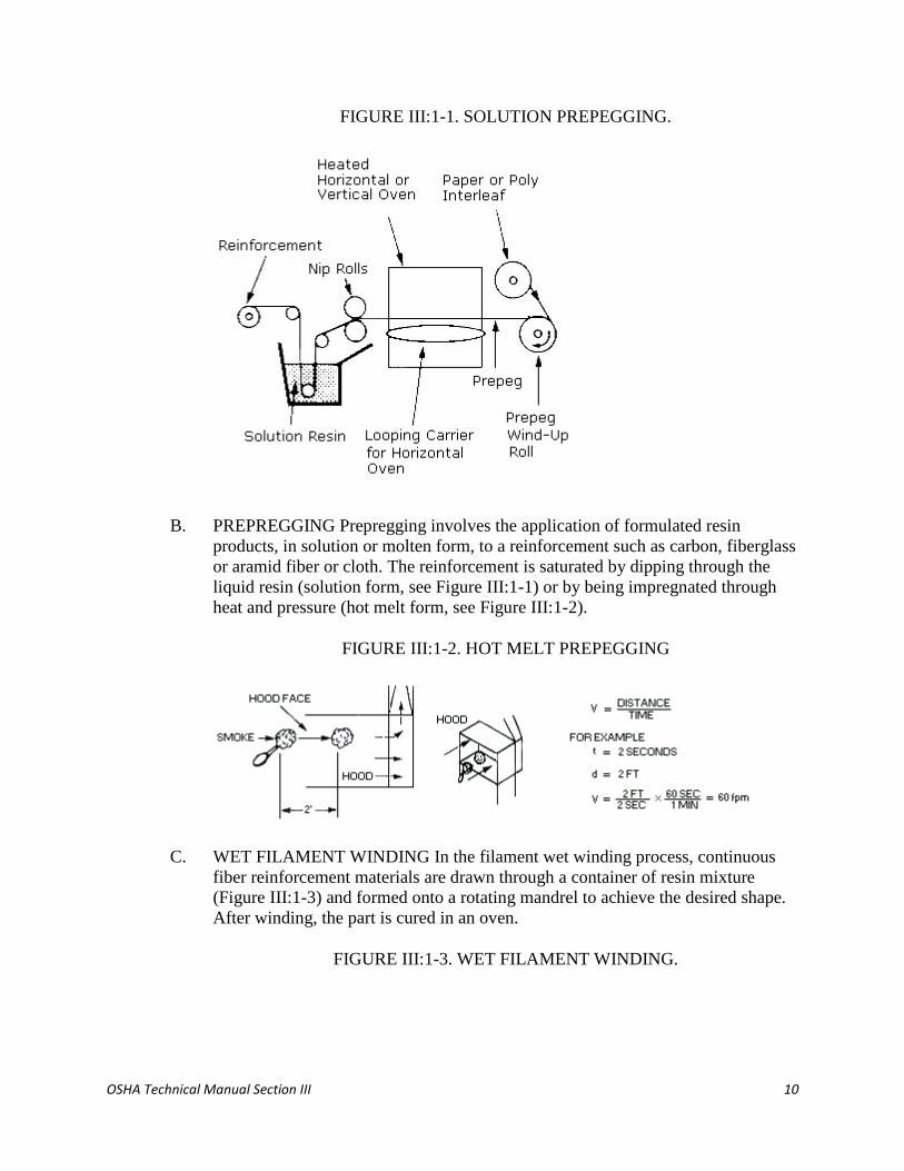
FIGURE III:1-1. SOLUTION PREPEGGING.
B. PREPREGGING Prepregging involves the application of formulated resin
products, in solution or molten form, to a reinforcement such as carbon, fiberglass
or aramid fiber or cloth. The reinforcement is saturated by dipping through the
liquid resin (solution form, see Figure III:1-1) or by being impregnated through
heat and pressure (hot melt form, see Figure III:1-2).
FIGURE III:1-2. HOT MELT PREPEGGING
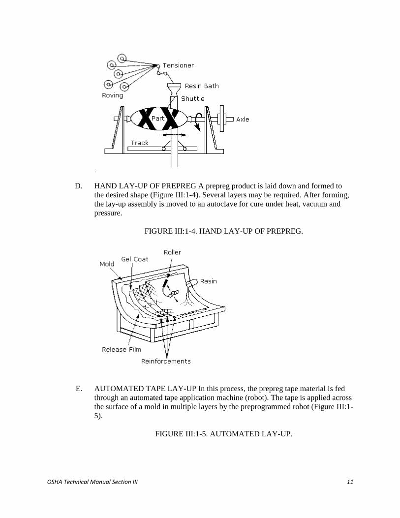
C. WET FILAMENT WINDING In the filament wet winding process, continuous
fiber reinforcement materials are drawn through a container of resin mixture
(Figure III:1-3) and formed onto a rotating mandrel to achieve the desired shape.
After winding, the part is cured in an oven.
FIGURE III:1-3. WET FILAMENT WINDING.
OSHA Technical Manual Section III 11
D. HAND LAY-UP OF PREPREG A prepreg product is laid down and formed to
the desired shape (Figure III:1-4). Several layers may be required. After forming,
the lay-up assembly is moved to an autoclave for cure under heat, vacuum and
pressure.
FIGURE III:1-4. HAND LAY-UP OF PREPREG.
E. AUTOMATED TAPE LAY-UP In this process, the prepreg tape material is fed
through an automated tape application machine (robot). The tape is applied across
the surface of a mold in multiple layers by the preprogrammed robot (Figure III:1-
5).
FIGURE III:1-5. AUTOMATED LAY-UP.
OSHA Technical Manual Section III 12
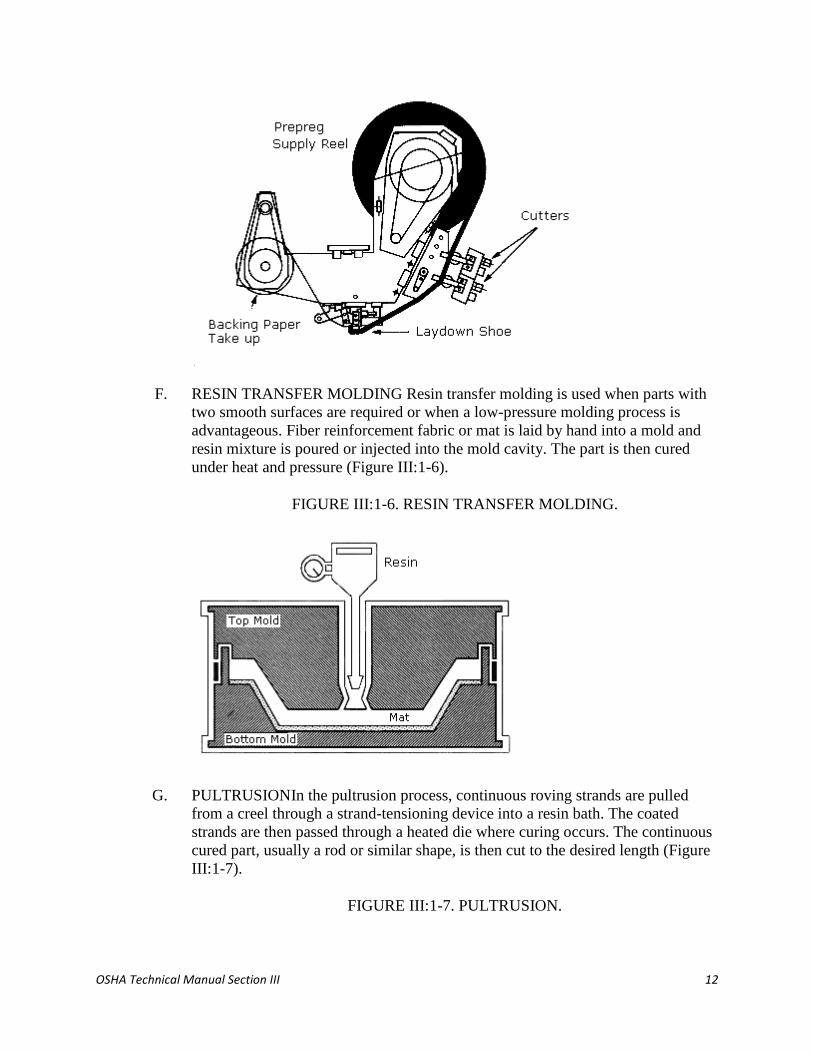
F. RESIN TRANSFER MOLDING Resin transfer molding is used when parts with
two smooth surfaces are required or when a low-pressure molding process is
advantageous. Fiber reinforcement fabric or mat is laid by hand into a mold and
resin mixture is poured or injected into the mold cavity. The part is then cured
under heat and pressure (Figure III:1-6).
FIGURE III:1-6. RESIN TRANSFER MOLDING.
G. PULTRUSIONIn the pultrusion process, continuous roving strands are pulled
from a creel through a strand-tensioning device into a resin bath. The coated
strands are then passed through a heated die where curing occurs. The continuous
cured part, usually a rod or similar shape, is then cut to the desired length (Figure
III:1-7).
FIGURE III:1-7. PULTRUSION.

OSHA Technical Manual Section III 13
H. INJECTION MOLDING One of the older plastics processes, injection molding is
also the most closed process. It is not normally used in PMC processes due to
fiber damage in the plasticating barrel. Thermoplastic granules are fed via a
hopper into a screw-like plasticating barrel where melting occurs (Figure III:1-8).
The melted plastic is injected into a heated mold where the part is formed. This
process is often fully automated.
FIGURE III:1-8. INJECTION MOLDING.
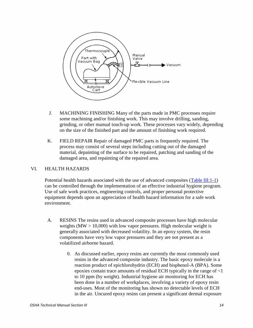
I. VACUUM BAGGING & AUTOCLAVE CURING Most parts made by hand lay-
up or automated tape lay-up must be cured by a combination of heat, pressure,
vacuum, and inert atmosphere. To achieve proper cure, the part is placed into a
plastic bag inside an autoclave (Figure III:1-9). A vacuum is applied to the bag to
remove air and volatile products. Heat and pressure are applied for curing.
Usually an inert atmosphere is provided inside the autoclave through the
introduction of nitrogen or carbon dioxide. Exotherms may occur if the curing
step is not done properly.
FIGURE III:1-9. VACUUM BAGGING AND AUTOCLAVE.
OSHA Technical Manual Section III 14
J. MACHINING FINISHING Many of the parts made in PMC processes require
some machining and/or finishing work. This may involve drilling, sanding,
grinding, or other manual touch-up work. These processes vary widely, depending
on the size of the finished part and the amount of finishing work required.
K. FIELD REPAIR Repair of damaged PMC parts is frequently required. The
process may consist of several steps including cutting out of the damaged
material, depainting of the surface to be repaired, patching and sanding of the
damaged area, and repainting of the repaired area.
VI. HEALTH HAZARDS
Potential health hazards associated with the use of advanced composites (Table III:1-1)
can be controlled through the implementation of an effective industrial hygiene program.
Use of safe work practices, engineering controls, and proper personal protective
equipment depends upon an appreciation of health hazard information for a safe work
environment.
A. RESINS The resins used in advanced composite processes have high molecular
weights (MW > 10,000) with low vapor pressures. High molecular weight is
generally associated with decreased volatility. In an epoxy system, the resin
components have very low vapor pressures and they are not present as a
volatilized airborne hazard.
0. As discussed earlier, epoxy resins are currently the most commonly used
resins in the advanced composite industry. The basic epoxy molecule is a
reaction product of epichlorohydrin (ECH) and bisphenol-A (BPA). Some
epoxies contain trace amounts of residual ECH typically in the range of <1
to 10 ppm (by weight). Industrial hygiene air monitoring for ECH has
been done in a number of workplaces, involving a variety of epoxy resin
end-uses. Most of the monitoring has shown no detectable levels of ECH
in the air. Uncured epoxy resins can present a significant dermal exposure

OSHA Technical Manual Section III 15
hazard. In many workplaces, manual processing results in potential skin
exposure. This can result in skin irritation, rashes and, subsequently,
dermatitis if contact is prolonged. Sensitization to the resins can also
develop and may require a change of work assignment.
1. Polyurethane resins are reaction products of polyols and isocyanates. The
significant hazard associated with these resin systems is the presence of
isocyanates. Exposure to highly toxic isocyanates can have adverse health
effects. Exposure to the vapor may cause irritation of the eyes, respiratory
tract and skin. Irritation may be severe enough to produce bronchitis and
pulmonary edema. Polyurethane resins contacting the eyes may cause
severe irritation, and if polyurethane resins are allowed to remain in
contact with the skin, they may produce redness, swelling, and blistering
of the skin. Respiratory sensitization (an allergic, asthmatic-type reaction)
may occur. Among the isocyanates, there is also evidence of cross-
sensitization, in which a worker is sensitized to one isocyanate but reacts
to others as well.
2. The phenol-formaldehyde resins must be handled with adequate
ventilation. Traces of free formaldehyde and phenol may be present.
Contact with these resins should be avoided because of the toxicity of
these components and the skin-absorption potential of phenol. These
components may also be given off during the curing process.
3. The acute toxicity of urea-formaldehyde resins is very similar to the
phenol-formaldehyde resins. Free formaldehyde, which is present in trace
amounts and may be liberated when the resins are processed, can have an
irritating effect on mucous membranes. Skin sensitization to formaldehyde
has been observed.
4. The health effects of bismaleimide resin systems have not been
extensively studied. Manufacturers of these materials indicate that
prolonged or repeated contact may cause skin irritation or sensitization.
Dust or vapor from heated products may cause irritation of the eyes, nose,
and throat.
5. Polyether and polyester polyols present no particular health hazard in
industrial processing.
6. Thermoplastic resins in general are not considered harmful to workers'
health. These resins appear harmless when ingested, and no skin irritation
has been reported. No toxic effects are known to be associated with the
inhalation of thermoplastic-resin dust. Treating it as nuisance or inert dust
seems appropriate, although the presence of unreacted monomers may be
of concern. These materials present a thermal hazard when handling.
Molding operations may give off vapors which are irritating to the eyes

OSHA Technical Manual Section III 16
and cause cold-like symptoms. Some thermoplastics are styrene-based,
and presence of this monomer may be of concern.
TABLE III:1-1. ORGAN SYSTEM TARGET.
Composite
component
Organ system target
(possible target)
Known (possible)
health effect
Resins
Epoxy resins Skin, lungs, eyes Contact and allergic dermatitis,
conjunctivitis
Polyurethane resins Lungs, skin, eyes Respiratory sensitization, contact
dermatitis, conjunctivitis
Phenol formaldehyde Skin, lungs, eyes As above (potential carcinogen)
Bismaleimides (BMI) Skin, lungs, eyes As above (potential carcinogen)
Polyamides Skin, lungs, eyes As above (potential carcinogen)
Reinforcing materialss
Aramid fibers Skin (lungs) Skin and respiratory irritation,
contact dermatitis (chronic
interstitial lung disease)
Carbon/graphite fibers Skin (lungs) As noted for aramid fibers
Glass fibers (continuous
filament)
Skin (lungs) As noted above
Hardeners and curing agentss
Diaminodiphenylsulfone -- No known effects with workplace
exposure
Methylenedianiline Liver, skin Hepatotoxicity, suspect human
carcinogen
Other aromatic aminess
Meta-phenylenediamine
(MPDA)
Liver, skin (kidney,
bladder)
Hepatitis, contact dermatitis
(kidney and bladder cancer)
Aliphatic andcyclo-
aliphatic amines
Eyes, skin Severe irritation, contact dermatitis

OSHA Technical Manual Section III 17
Polyaminoamide Eyes, skin Irritation (sensitization)
Anhydride Eyes, lungs, skin Severe eye and skin irritation,
respiratory sensitization, contact
dermatitis
B. CURING AGENTS
1. Curing agents, or hardeners, used with the epoxy resins are mostly
amines, amides, or anhydrides. Two of the most widely used are
the aromatic amines, MDA (4,4'-methylenedianiline) and DDS
(4,4'-diaminodiphenyl-sulfone).
2. Analysis and review of epidemiologic data and human and animal
toxicity data indicates that occupational exposure to MDA may
result in reversible liver toxicity (hepatotoxicity). The retina of the
eye might be damaged not only by direct contact but also from
MDA absorbed through ingestion. MDA is an animal carcinogen
and a suspect human carcinogen by any exposure route: ingestion,
inhalation, or dermal.
3. Frequently, curing agents containing mixtures of these amines can
cause skin staining in processes requiring dermal contact, even
when protective gloves are used. Brown and orange stains on walls
and ceilings have also been reported. The skin staining has been
attributed to MDA; dermal absorption is approximately 2% per
hour. Soap and water, rather than any organic solvent, should be
used for skin clean-up to avoid any solvent increase of transdermal
absorption.
4. The OSHA permissible exposure limits (PEL'S) for MDA are 10
ppb (parts per billion) expressed as an 8-hour time-weighted
average, and a short-term exposure limit (STEL) of 100 ppb
averaged over any 15-minute period for either general industry or
construction uses of MDA. The FR 57(154): 35630 (August 10,
1992) issue published the Final Rule for 29 CFR Parts 1910 and
1926: Occupational Exposure to 4,4'Methylenedianiline (MDA).
5. Another of the amines, DDS, has a significant amount of
toxicological data as its pharmaceutical grade, DapsoneTM, has
been used for years to treat leprosy and certain types of chronic

OSHA Technical Manual Section III 18
dermal inflammation. However, at low airborne concentrations,
there are no known effects from workplace exposure.
6. Other aromatic amines used in the advanced composites industry
include m-phenylene diamine and the various isomers of
toluenediamine. These aromatic amines are considered to be only
slightly irritating to the skin.
7. Aliphatic and cycloaliphatic amines are strong bases and are
considered to be severe eye and skin irritants. Inhalation of these
amines can cause irritation of the nose and throat, and lung
irritation with respiratory distress. Some of these amines are also
skin and respiratory-tract sensitizers. Vapors of the volatile amines
may cause conjunctivitis and visual disturbances.
8. Polyaminoamide hardeners have a less irritating effect on the skin
and mucous membranes than the aliphatic and cycloaliphatic
amine hardeners, but may cause sensitization.
9. Amide hardeners generally have only a slight irritant effect. Should
the handling of these hardeners generate dust, measures should be
taken to prevent inhalation.
10. The dusts of high-melting solids like most anhydride curing agents
are severe eye and skin irritants. Some hydrophthalic anhydrides
have high vapor pressures at the usual processing and curing
temperatures and the vapors evolved during use of these curing
agents can have an irritating effect on the skin, eyes, and
respiratory tract. Exposure to the high-melting solids like
trimellitic anhydride and tetraphthalic anhydride can cause
respiratory sensitization.
C. REINFORCEMENT FIBERS Most of the reinforcing materials used in
the industry have the potential to cause eye, skin, and upper respiratory
tract irritation as a result of the mechanical-irritant properties of the fibers.
The potential synergism has not been clearly defined. The chemical
irritation caused by resins can compound the mechanical irritation caused
by the fibers.
1. Carbon/graphite fibers dominate the advanced composites industry
and may be made from any of three precursors, as discussed in
Section C. However, the PAN-based carbon fibers are the
predominant form in use today. It is important to ascertain which
type of carbon-fiber precursor is used in order to evaluate the
hazards.
Pitch-based carbon fibers may be associated with an increased risk

OSHA Technical Manual Section III 19
of skin cancer, although the evidence is weak. PAN-based carbon
fibers did not cause tumors when the same test was conducted.
Standard mutagenicity tests conducted on PAN-based carbon
fibers were negative.
The principal hazards of carbon-fiber handling are mechanical
irritation and abrasion similar to that of glass fibers. Skin rashes
are common and reportedly more severe than from glass fibers.
Carbon fibers commonly in use are also greater than six
micrometers in diameter, making them unlikely to be respirable.
An ongoing survey of workers in a carbon-fiber production plant
shows no pulmonary function abnormalities and no evidence of
dust-related disease.
Carbon fibers may be coated with a material to improve handling,
known generically as sizing. The sizing materials are typically
epoxy resins. They may be biologically active and cause irritation
or sensitization.
2. Aramid fibers are made from a polymer, poly(p-phenylenediamine
terephthalate). Animal and human skin tests of KevlarTM aramid
fibers show no potential for skin sensitization and low potential for
irritation. While KevlarTM fibers are too large to be inhaled (12-15
mm), they may be fractured into respirable fibrils in some
composite manufacturing processes. Industrial process monitoring
shows that airborne respirable fibril levels are low in typical
operations. Measured exposure levels from composite machining
are typically below 0.2 fibrils per milliliter of air (0.2 f/ml), as an
8-hour, time-weighted average (TWA), while continuous filament
handling generates less than 0.1 f/ml. The physical structure of
aramid fibers makes it extremely difficult to generate airborne
concentrations.
3. Glass fibers, used as reinforcement in PMC processes, are a
continuous-filament form and not the glass-wool (random) type.
Practically all glass fibers for composite reinforcement are greater
than six microns in diameter. Airborne fiber of this diameter does
not reach the alveoli and is nonrespirable. Glass fibers break only
into shorter fragments of the same diameter. Their diameter cannot
be reduced by machining, milling, or other mechanical processes.
Mechanical irritation of skin, eyes, nose, and throat are common
hazards associated with glass-fiber exposure. Continuous-filament
glass fiber is not considered fibrogenic. Lung clearance
mechanisms are effective for glass fibers.
In June 1987, the International Agency for Research on Cancer
OSHA Technical Manual Section III 20
(IARC) categorized continuous-filament glass fibers as not
classifiable with respect to human carcinogenicity. The evidence
from human and animal studies was evaluated by IARC as
insufficient to classify continuous-filament glass fibers a possible,
probable, or confirmed cancer-causing material.
Like carbon fibers, glass fibers may also be coated with a sizing
material to improve handling. Sizing materials may be epoxy
resins, polyvinyl acetate-chrome chloride, polyvinyl acetate-silane,
polyester-silane, or epoxy-silane compounds. These materials may
be biologically active and cause irritation or sensitization.
D. DUSTS
1. Dusts may be generated in several ways in advanced composite
processes. The most common dust-generating processes are
machining and finishing of cured parts and in repair of damaged
parts. Much of the dust generated in these processes can be very
fine and should be considered respirable. Studies of some graphite-
epoxy finishing operations found respirable fractions ranging from
25% to 100%.
2. More dust is usually generated in finishing and repair processes
since large surface areas are involved. Grinding, routing and
sanding are frequently used methods in both processes. The repair
process may require the use of abrasive blasting as well as sanding
to remove existing paint or coatings. Typically, a synthetic blasting
agent, e.g., plastic media blast, is used. Ingredients of the paint or
coating being removed, such as lead or chromates, may also be of
concern. The repair process may also require cutting or sawing to
remove the damaged part area, and both may generate significant
amounts of airborne dust.
3. In general, studies on composite dusts indicate that:
The dusts are particulate in nature and usually contain few
fibers;
The dusts are thermally stable up to 250 °C and exhibit a
high degree of cure; and
Toxicology studies indicate the dusts should probably be
controlled at levels below the PEL for inert dust, but not
approaching the PEL for crystalline quartz.
E. SOLVENTS
1. Many of the solvents used in advanced composite processes are
volatile and flammable. Most are skin and eye irritants, and some

OSHA Technical Manual Section III 21
may be readily absorbed through the skin. Precautions must be
taken when using organic solvents because they can facilitate the
entry of toxic materials into the skin and organ systems. They may
also enhance skin sensitization caused by the resin systems. Some
(such as methyl alcohol) are poisonous, and all are capable of
extracting fat from skin. Harmful effects from industrial exposures
come principally from skin contact and inhalation.
2. Selection of the proper glove for protection is important.
Permeation data are available for many industrial chemicals,
especially solvents. However, in the case of resins and curing
agents, not much data are available. This also is true for mixtures
of solvents, as little or no testing has been done. Often the glove
selection process is one of trial and error. If a skin rash or
dermatitis is observed there are several possible causes:
the wrong gloves may have been selected;
improper work practices are being followed;
the employee is deficient in personal hygiene practices; or
adequate washing facilities are absent.
3. Several of the solvent classes most commonly found in the PMC
workplace are listed below, along with general hazard information.
4. Several ketones are frequently found in PMC manufacture. These
include:
acetone (DMK)
methyl ethyl ketone (MEK)
methyl isobutyl ketone (MIBK)
These solvents may cause eye, nose, and throat irritation, and
prolonged contact with the liquid may result in defatting of the
skin and resultant dermatitis. In high concentrations, narcosis is
produced with symptoms of headache, nausea, light-headedness,
vomiting, dizziness, incoordination, and unconsciousness. Ketones
are volatile and flammable. Acetone is a popular solvent used for
cleanup and may be found around the workplace in containers for
this purpose.
5. Some of the lower-boiling alcohols are sometimes used in
composites manufacture. These include:
methanol (methyl alcohol)

OSHA Technical Manual Section III 22
ethanol (ethyl alcohol)
isopropanol (isopropyl alcohol)
These alcohols do not usually present serious hazards in the
industrial setting. Toxicity is usually related to irritation of the
conjunctivae and the mucous membranes of the upper airway.
Contact with the liquid may cause defatting of the skin and
dermatitis. These alcohols are volatile and flammable.
6. Three chlorinated hydrocarbon compounds in particular are found
in the composites workplace:
methylene chloride (dichloromethane)
1,1,1-trichloroethane (methyl chloroform)
trichloroethylene
Health effects typical of the group include irritation of the eyes and
upper respiratory tract, dizziness, confusion, drowsiness, nausea,
vomiting, and occasionally abdominal pain. Visual disturbances
may also occur. Due to the solvents' defatting properties, repeated
or prolonged skin contact with these liquids may cause dermatitis.
Ability to depress the central nervous system is a characteristic
property of all members of this group.
These solvents are not particularly flammable. Many
manufacturers have replaced the ketones with the above
hydrocarbon solvents to reduce the risk of flammability.
7. Other solvents that may occasionally be used are:
toluene
xylene
tetrahydrofuran (THF)
dimethylsulfoxide (DMSO)
dimethylformamide (DMF)
gamma-butyrolactone (BLO)
n-methyl pyrrolidone (NMP)
n-butyl acetate
glycol ethers
Technical literature including MSDS's from the solvent supplier
should be consulted about these or any chemicals used with
advanced composites.

OSHA Technical Manual Section III 23
VII. WORKPLACE CONTROLS
Good workplace controls are essential in controlling exposure to process
materials. Many of the materials, particularly the resins, curing agents, and fibers,
present a potential dermal-exposure hazard. Many of the solvents and some of the
curing agents present a potential inhalation hazard. Some materials present both a
dermal and inhalation hazard. Ingestion may be a potential exposure hazard, but
usually involves poor personal hygiene or contamination of eating facilities. The
various types of workplace controls described below may typically be found in
the advanced composite workplace.
B. ENGINEERING CONTROLS Isolation (e.g., isolated storage, separate
process areas, enclosures, closed systems) and local exhaust ventilation
are the primary engineering controls found in advanced composites
processes. These controls can be found in:
Resin mixing areas;
Heated curing areas including autoclaves;
Finishing and repair areas; and
Controlling off-gases from exotherms
C. WORK PRACTICE CONTROLS Work practices, as distinguished from
engineering controls, involve the way a task is performed. Some
fundamental and easily implemented work practices that can be used to
minimize exposures when working with advanced composites are:
good employee training and education;
following the proper procedures for production, process and
control equipment;
proper use, maintenance, and cleaning of personal protective
equipment;
good personal hygiene program;
housekeeping;
periodic inspection and maintenance of production, process and
control equipment; and
good supervision.
D. PERSONAL PROTECTIVE EQUIPMENT
1. Gloves, protective clothing, and eye protection may frequently be
required, especially when working with resins, curing agents, and
solvents. Selection of the proper protective materials should be
OSHA Technical Manual Section III 24
based on permeation data, if available. This type of data are often
available for the solvents used, but very little data are available for
the resins and curing agents.
2. In many advanced composites processes several chemicals or
mixtures are involved. There are essentially no permeation data
available for chemical mixtures. This means that, in many cases,
glove and clothing selection must be a trial and error process.
3. Generally, the resins are of a larger molecular size and so are less
likely to permeate protective materials than the curing agents and
solvents. The aromatic amine curing agents are particularly
difficult to protect against. In some advanced composites
processes, close hand work and contact is required, and a glove
must provide good tactility. Often this type of glove provides the
least protection against the resin and curing agent.
4. Eye protection can be provided by standard safety glasses with side
shields, goggles, or a face shield, as needed.
5. Respiratory protection is not required in many advanced
composites processes, due to the low vapor pressure of the
materials involved. However, respirators may be required where:
Airborne solvent levels are high;
Dust levels are high (resin mixing, finishing, repair);
Large surface areas and significant hand work are involved;
and
Exotherms are experienced.
E. ADMINISTRATIVE CONTROLS Employee exposures also can be
controlled by scheduling operations with the highest exposures at a time
when the fewest employees are present.
VIII. BIBLIOGRAPHY
Advanced Composites Glossary. Blaise Technoire, San Marcos, Calif.
Doyle, E.J. Suggested Strategies in Screening for Health Effects in Personnel who Work
with Composites. Applied Industrial Hygiene Special Issue: December 1989. Pp 64-67.
Engineered Materials Handbook, Vol. 1: Composites. ASM International, Metals Park,
Ohio: 1987.
Lubin, G., Ed. Handbook of Composites. Van Nostrand Reinhold Co., New York: 1982.

OSHA Technical Manual Section III 25
Occupational Safety and Health Administration, Department of Labor, Final Rule:
Occupational Exposure to 4,4'Methylenedianiline (MDA) for 29 CFR Parts 1910 and
1926. Federal Register 57(154): 35630 (August 10, 1992)
APPENDIX III:1-1. GLOSSARY.
[Adapted from Advanced Composites Magazine, 1992 Bluebook, Edgell Plastics
Publications]
A-stage An early stage of polymerization of thermosetting resins in which the material
is still soluble in certain liquids and is fusible. Also called resole. See also B-stage, C-
stage.
Ablative A material that absorbs heat through a decomposition process called pyrolysis
at or near the exposed surface.
Addition A polymerization reaction in which no by-products are formed.
Additives Ingredients mixed into resin to improve properties.
Adhesive failure A rupture of adhesive bond that appears to be a separation at the
adhesive-adherend interface.
Amorphous Polymers that have no order to their molecules, thus no crystalline
component.
Anisotropic The tendency of a material to exhibit different properties in response to
stresses applied along axes in different directions.
Aramid Aromatic polyamide fibers characterized by excellent high-temperature, flame-
resistance, and electrical properties. Aramid fibers are used to achieve high-strength,
high-modulus reinforcement in plastic composites.
Areal weight The weight of fiber per unit area (width times length) of tape or fabric.
Aspect ratio The ratio of length to diameter of a fiber.
Autoclave A closed vessel that permits application of pressure and heat used for curing
composites.
Autoclave molding A molding technique in which an entire assembly (layup) is placed
into an autoclave at 50 to 100 psi, in order to consolidate layers of the part by removing
entrapped air and volatiles. Usually includes application of heat to trigger curing of the
resin.
Axial winding A type of filament winding in which the filaments are parallel to the axis.

OSHA Technical Manual Section III 26
B-stage Intermediate stage in the polymerization reaction of thermosets, following
which material will soften with heat and is plastic and fusible. Also called resistal. The
resin of an uncured prepreg or premix is usually in B-stage. See A-stage, C-stage.
Bag molding A technique in which the composite material is placed in a rigid mold and
covered with a flexible bag, with pressure applied by vacuum, autoclave, press, or by
inflating the bag.
Balanced laminate All lamina except those at 0/90 are placed in plus-minus pairs (not
necessarily adjacent) symmetrically about the layup centerline.
Bearing strength The maximum bearing stress that will not cause a composite to fail
when applied through a cylindrical fastener surface.
Bearing stress Applied load divided by bearing area (hole diameter times thickness).
Bias fabric A fabric in which warp and fill fibers are at an angle to the length.
Biaxial winding A type of filament winding in which the helical band is laid in
sequence, side by side, with no crossover of the fibers.
Bidirectional laminate A reinforced plastic laminate in which the fibers are oriented in
more than one direction in the plane of the laminate.
Bismaleimide A type of polyimide that cures by an addition reaction, avoiding
formation of volatiles, and has temperature capabilities between those of epoxy and
polyimide.
Bleeder cloth A layer of woven or nonwoven material, not a part of the composite, that
allows excess gas and resin to escape during cure.
Bleedout The excess liquid resin appearing at the surface, primarily during filament
winding.
Bond strength The amount of adhesion between bonded surfaces. As measured by
load/bond area, the stress required to separate a layer of material from that to which it is
bonded.
Boron fiber A fiber usually of a tungsten-filament core with elemental boron vapor
deposited on it to impart strength and stiffness.
Braiding Weaving fibers into a tubular shape.
Breather A loosely woven material that does not come in contact with the resin but
serves as a continuous vacuum path over a part in production.
OSHA Technical Manual Section III 27
Broadgoods Fibers woven into fabrics that may or may not be impregnated with resin,
usually furnished in rolls.
Buckling (composite) A failure usually characterized by fiber deflection rather than
breaking because of compressive action.
Butt joint A joint in which parts are joined with no overlap.
C-stage The final step in the cure of a thermoset resin; results in essentially irreversible
hardening and insolubility.
Carbon/carbon A composite of carbon fiber in a carbon matrix.
Carbon fiber An important reinforcing fiber known for its light weight, high strength,
and high stiffness that is produced by pyrolysis of an organic precursor fiber in an inert
atmosphere at temperatures above 1,800° F. The material may also be graphitized by heat
treating above 3,000° F.
Catalyst A substance used in small quantities to promote or control the curing of a
compound without being consumed in the reaction.
Caul sheet Plate or sheet the same size and shape used in contact with a composite layup
to transmit normal pressure and temperature during cure.
Ceramic-matrix composites Materials consisting of a ceramic or carbon fiber
surrounded by a ceramic matrix, usually SiC (silicon carbide).
Chemical vapor deposition (CVD) A process in which desired reinforcement material is
deposited from vapor phase onto a continuous core; boron on tungsten, for example.
Circuit One complete traverse of the fiber feed mechanism of a filament-winding
machine.
Circumferential winding A type of filament winding in which the filaments are
perpendicular to the axis.
Co-cured Cured and simultaneously bonded to another prepared surface.
Coefficient of thermal expansion A material's fractional change in length for a given
unit change of temperature.
Commingled yarn A hybrid yarn made with two types of materials intermingled in a
single yarn; for example, thermoplastic filaments intermingled with carbon filaments to
form a single yarn.

OSHA Technical Manual Section III 28
Composite A material created from a fiber (or reinforcement) and an appropriate matrix
material in order to maximize specific performance properties. The constituents do not
dissolve or merge completely but retain their identities as they act in concert.
Compression molding A technique for molding thermoset plastics in which a part is
shaped by placing the fiber and resin into an open mold cavity, closing the mold, and
applying heat and pressure until the material has cured or achieved its final form.
Compressive strength A material's ability to resist a force that tends to crush or buckle;
maximum compressive load a specimen sustains divided by the specimen's original cross-
sectional area.
Condensation A polymerization reaction in which simple by-products (for example,
water) are formed.
Consolidation A processing step that compresses fiber and matrix to reduce voids and
achieve a desired density.
Contact molding A technique in which reinforcement and resin are placed in a mold,
with cure taking place at room temperature with a catalyst/promoter system, or in a
heated oven. No additional pressure is used.
Continuous filament An individual, small-diameter reinforcement that is flexible and
indefinite in length.
Continuous-filament yarn Yarn that is formed by twisting two or more continuous
filaments into a single continuous strand.
Continuous roving Parallel filaments coated with sizing, gathered together into single or
multiple strands, and wound into a cylindrical package. It may be used to provide
continuous reinforcement in woven roving, filament winding, pultrusion, prepregs, or
high-strength molding compounds, or it may be used chopped.
Core The central component of a sandwich construction to which the sandwich faces or
skins are attached; also, part of a complex mold that forms undercut parts.
Co-woven fabric A reinforcement fabric woven with two different types of fibers in
individual yarns; for example, thermoplastic fibers woven side by side with carbon fibers.
Creep The dimensional change in a material under physical load over time beyond
instantaneous elastic deformation.
Crimp A fiber's waviness, which determines the capacity of the fiber to cohere.
Critical length The minimum length of a fiber necessary for matrix shear loading to
develop fiber ultimate strength by a matrix.

OSHA Technical Manual Section III 29
Cross laminated Material laminated so that some of the layers are oriented at various
angles to the other layers with respect to the laminate grain. A cross-ply laminate usually
has plies oriented only at 0°/90°.
Crystallinity The quality of having a molecular structure with atoms arranged in an
orderly, three-dimensional pattern.
Cure To change the physical properties of a material irreversibly by chemical reaction
via heat and catalysts, alone or in combination, with or without pressure.
Cure temperature The temperature at which a material attains final cure.
Curing agent A catalytic or reactive agent that brings about polymerization when it is
added to a resin.
Damage tolerance A measure of the ability of structures to retain load-carrying
capability after exposure to sudden loads (for example, ballistic impact).
Damping Diminishing the intensity of vibrations.
Debond An unplanned nonadhered or unbonded region in an assembly.
Delamination The separation of a laminated plastic material along the plane of its layers.
Denier A numbering system for yarn and filament in which yarn number is equal to
weight in grams of 9000 meters of yarn.
Design allowable A limiting value for a material property that can be used to design a
structural or mechanical system to a specified level of success with 95% statistical
confidence. B-basis allowable: material property exceeds the design allowable 90 times
out 100. A-basis allowable: material property exceeds the design allowable 99 times out
of 100.
Doubler Localized area of extra layers of reinforcement, usually to provide stiffness or
strength for fastening or other abrupt load transfers.
Draft angle A mandrel's taper or angle for ease of part removal.
Drape The ability of prepreg to conform to the shape of a contoured surface.
Dry winding A type of filament winding in which preimpregnated roving is used.
E-glass "Electrical glass"; the borosilicate glass most often used for the glass fibers in
conventional reinforced plastics.

OSHA Technical Manual Section III 30
Fabric, nonwoven A material formed from fibers or yarns without interlacing.
Fabric, woven A material constructed of interlaced yarns, fibers, or filaments.
Fatigue The failure of a material's mechanical properties as a result of repeated stress.
Fatigue strength Maximum cyclical stress withstood for a given number of cycles before
a material fails.
Fiber orientation The fiber alignment in a nonwoven or a mat laminate in which most of
the fibers are in the same direction, thereby affording higher strength in that direction.
Fiber placement A continuous process for fabricating composite shapes with complex
contours and/or cutouts by means of a device that lays preimpregnated fibers (in tow
form) onto a nonuniform mandrel or tool. It differs from filament winding (below) in
several ways: there is no limit on fiber angles; compaction takes place online via heat,
pressure, or both; and fibers can be added and dropped as necessary. The process
produces more complex shapes and permits a faster putdown rate than filament winding.
Filament winding A process for fabricating composites in which continuous reinforcing
fibers, either preimpregnated with resin or drawn through a resin bath, are wound around
a rotating, removable mandrel.
Filaments Individual fibers of indefinite length used in tows, yarns, or roving.
Film adhesive An adhesive in the form of a thin, dry, resin film with or without a
carrier, commonly used for adhesion between layers of laminates.
Finish Material applied to fibers, after sizing is removed, to improve matrix-to-fiber
coupling.
Fracture A rupture of the surface of a laminate because of external or internal forces,
with or without complete separation.
Fracture toughness A measure of the damage tolerance of a material containing initial
flaws or cracks.
Glass transition The reversible change in an amorphous polymer between a viscous or
rubbery condition and a hard, relatively brittle one.
Glass-transition temperature (Tg) The approximate temperature at which increased
molecular mobility results in significant changes in properties of a cured resin. The
measured value of Tg can vary depending upon the test method.
Hand layup A fabrication method in which reinforcement layers, preimpregnated or
coated afterwards, are placed in a mold by hand, then cured to the formed shape.

OSHA Technical Manual Section III 31
Hardener A substance used to promote or control curing action by taking part in it; as
opposed to catalyst.
Heat-distortion temperature Temperature at which a test bar deflects a certain amount
under specified temperature and a stated load.
Honeycomb Resin-impregnated material manufactured in, usually, hexagonal cells that
serves as a core material in sandwich constructions. Honeycomb may also be metallic or
polymer materials in a rigid, open-cell structure.
Hoop stress Circumferential stress in a cylindrically shaped part as a result of internal or
external pressure.
Hybrid composite A composite with two or more reinforcing fibers.
Impact strength A material's ability to withstand shock loading as measured by the work
done in fracturing a specimen.
Impregnate To saturate the voids and interstices of a reinforcement with a resin.
Impregnated fabric See Prepreg.
Interface The surface between two different materials: in fibers, the area at which the
glass and sizing meet; in a laminate, the area at which the reinforcement and the
laminating resin meet.
Interlaminar Existing or occurring between two or more adjacent laminae.
Interlaminar shear The shearing force tending to produce displacement between two
laminae along the plane of their interface; usually the weakest element of a composite.
Isotropic. Having uniform properties in all directions independent of the direction of load
application.
Laminate ply One layer of a laminated product.
Lap joint A joint made by bonding overlapped portions of two adherends.
Layup The placement of layers of reinforcement in a mold.
Liquid-crystal polymers A newer type of thermoplastic, melt processible, with high
orientation in molding, improved tensile strength, and high-temperature capability.
Mandrel. The form around which resin-impregnated fiber or tape is wound to form
structural shapes or tubes.

OSHA Technical Manual Section III 32
Mat A fibrous reinforcing material comprised of chopped filaments (for chopped-strand
mat) or swirled filaments (for continuous-strand mat) with a binder to maintain form;
available in blankets of various widths, weights, and lengths.
Matrix A material in which the fiber of a composite is imbedded; it can be plastic,
metal, ceramic, or glass.
Metal-matrix composites Materials in which continuous carbon, silicon carbide, or
ceramic fibers are embedded in a metallic matrix material.
Modulus A measure of the ratio of load (stress) applied to the resultant deformation of a
material, such as elasticity or shear.
Multifilament A yarn consisting of many continuous filaments.
Nondestructive inspection (NDI) A process or procedure for determining material or
part characteristics without permanently altering the test subject. Nondestructive testing
(NDT) is broadly considered synonymous with NDI.
Nonwoven roving A reinforcement composed of continuous rovings loosely gathered
together.
Oriented materials Composites whose constituents are aligned in a particular way.
Out-life The period of time a prepreg material remains in a handleable form and with
properties intact outside of the specified storage environment; for example, out of the
freezer in the case of thermoset prepregs.
PAN See Polyacrylonitrile.
Peel ply Layer of material applied to a prepreg layup surface that is removed from the
cured laminate prior to bonding operations and leaves a clean resin-rich surface ready for
bonding.
Peel strength Strength of an adhesive bond obtained by stress applied "in a peeling
mode." Pitch A residual petroleum product used in the manufacture of certain carbon
fibers.
Planar winding A type of filament winding in which the filament path lies on a plane
that intersects the winding surface.
Ply The number of single yarns twisted together to form a plied yarn; one of the layers
that make up a stack or laminate.
Polar winding A type of filament winding in which the filament path passes tangent to
OSHA Technical Manual Section III 33
the polar opening at one end of the chamber and tangent to the opposite side of the polar
opening at the other end of the chamber.
Polyacrylonitrile (PAN) A product used as a base material in the manufacture of certain
carbon fibers.
Polymer A very large molecule formed by combining a large number of smaller
molecules, called monomers, in a regular pattern.
Polymerization A chemical reaction in which the molecules of monomers are linked
together to form polymers.
Postcure An additional elevated-temperature exposure that is performed often without
tooling or pressure to improve elevated-temperature mechanical properties, for example.
Pot life The length of time a catalyzed thermosetting resin system retains a viscosity low
enough for it to be suitable for processing.
Precure The full or partial setting of a resin or adhesive before the clamping operation is
complete or before pressure is applied.
Precursor For carbon fibers, the rayon, PAN, or pitch fibers from which carbon fibers
are made.
Preform A fibrous reinforcement preshaped to approximate contour and thickness
desired in the finished part.
Prepreg Resin-impregnated cloth, mat, or filaments in flat form that can be stored for
later use. The resin is often partially cured to a tack-free state called "B-staging."
Catalysts, inhibitors, flame retardants, and other additives may be included to obtain
specific end-use properties and improve processing, storage, and handling characteristics.
Pressure-bag molding A molding technique in which a flexible bag is placed over the
contact layup in the mold, sealed, and clamped in place, and pressure applied by
compressed air, which forces the bag against the part while the part cures.
Pultrusion A continuous process for manufacturing composites in rods, tubes, and
structural shapes having a constant cross-section. After the reinforcement is passed
through the resin-impregnation bath, it is drawn through a shaping die to form the desired
cross-section; curing takes place before the laminate can depart from that cross-section.
Quasi-isotropic Approximating isotropy by orientation of plies in several directions.
Ramping A gradual, programmed increase or decrease in temperature or pressure to
control the cure or cooling of composite parts.

OSHA Technical Manual Section III 34
Reinforcement A material added to the matrix to provide the required properties; ranges
from short fibers through complex textile forms.
Release agents Materials that are used to prevent cured matrix material from bonding to
tooling.
Release film An impermeable film layer that does not bond to the composite during
cure.
Resin A material, generally a polymer, that has an indefinite and often high molecular
weight and a softening or melting range and exhibits a tendency to flow when it is
subjected to stress. Resins are used as the matrices to bind together the reinforcement
material in composites.
Resin rich Localized area filled with resin but lacking reinforcement fiber.
Resin starved Localized area lacking sufficient resin for wetout of the fibers.
Resin-transfer molding (RTM) A molding process in which catalyzed resin is
transferred into an enclosed mold into which the fiber reinforcement has been placed;
cure normally is accomplished without external heat. RTM combines relatively low
tooling and equipment costs with the ability to mold large structural parts.
Roving A collection of bundles of continuous filaments either as untwisted strands or as
twisted yarns.
S-glass Structural glass; a magnesia/alumina/silicate glass reinforcement designed to
provide very high tensile strength.
Sandwich construction A composite composed of a lightweight core material (usually
honeycomb or foamed plastic) to which two relatively thin, dense, high-strength,
functional, or decorative skins (also called faces) are adhered.
Scarf joint A bonded joint in which similar segments of adherends are cut away, with
cut areas overlapped and bonded.
Selvage The narrow edge of woven fabric that runs parallel to the warp. It is made with
stronger yarns in a tighter construction than the body of the fabric to prevent raveling.
Shelf life The length of time a material can be stored and continue to meet specification
requirements and remain suitable for its intended use.
Silicon carbide fiber A reinforcing fiber with high strength and modulus; density is
equal to that of aluminum. It is used in organic metal-matrix composites.
Sizing A compound that binds together and stiffens warp yarn to provide resistance to

OSHA Technical Manual Section III 35
abrasion during weaving; normally removed and replaced with finish before matrix
application.
Skin A layer of relatively dense material used in a sandwich construction on the surface
of the core.
Specific gravity The density (mass per unit volume) of a material divided by that of
water at a standard temperature.
Starved joint A joint that does not have the proper amount of adhesive because of
insufficient spread or excessive pressure.
Stiffness The relationship of load to deformation for a particular material.
Storage life The amount of time a material can be stored and remain suitable for use.
Strain The elastic deformation of a material as a result of stress.
Stress The internal force that resists change in size or shape, expressed in force per unit
area.
Structural adhesive An adhesive used for transferring loads between adherends.
Structural bond A bond joining load-bearing components of an assembly.
Tack The stickiness of a prepreg.
Tape A unidirectional woven prepreg, in widths up to 12 inches for carbon fiber, for
example.
Tape laying A fabrication process in which prepreg tape is laid side by side or
overlapped to form a structure.
Tensile strength The maximum tensile stress sustained by a plastic specimen before it
fails in a tension test.
Thermal conductivity The ability of a material to conduct heat.
Thermoplastic A plastic material that is capable of being repeatedly softened by
application of heat and repeatedly hardened by cooling.
Thermoset A plastic material that is capable of being cured by heat or catalyst into an
infusible and insoluble material. Once cured, a thermoset cannot be returned to the
uncured state.
Tooling resins Plastic resins, chiefly epoxy and silicone, that are used as tooling aids.

OSHA Technical Manual Section III 36
Toughness Tendency of a material to absorb work.
Tow An untwisted bundle of continuous filaments, usually designated by a number
followed by "K," indicating multiplication by 1,000; for example, 12K tow has 12,000
filaments.
Unbond Area of a bonded surface in which bonding of adherends has failed to occur, or
where two prepreg layers of a composite fail to adhere to each other; also denotes areas
where bonding is deliberately prevented to simulate a defective bond.
Unidirectional Refers to fibers that are oriented in the same direction, such as
unidirectional fabric, tape, or laminate, often called UD.
Vacuum bag molding A molding technique in which the part is cured inside a layer of
film, from which entrapped air is removed by vacuum.
Viscosity The tendency of a material to resist flow.
Voids Pockets of entrapped gas that have been cured into a laminate.
Volatiles Materials in a sizing or a resin formulation that can be vaporized at room or
slightly elevated temperature.
Warp The yarns running lengthwise and parallel to the selvage in a woven fabric.
Water jet A high-pressure stream of water used for cutting organic composites.
Weave The pattern by which a fabric is formed from interlacing yarns. In plain weave,
the warp and fill fibers alternate to make both fabric faces identical; in satin weave, the
pattern produces a satin appearance, with the warp tow over several fill tows and under
the next one (for example, eight-harness satin would have warp tow over seven fill tows
and under the eighth).
Weft The yarns running perpendicular to the warp in a woven fabric; also called "woof."
Wet layup The application of resin to dry reinforcement in the mold.
Wet winding A type of filament winding in which the fiber strand is impregnated with
resin immediately before it contacts the mandrel.
Wetout The saturation of all voids between strands and filaments of porous materials
with resin.
Wetting agent A surface-active agent that promotes wetting by decreasing the cohesion
within a liquid.

OSHA Technical Manual Section III 37
Winding pattern The regularly recurring pattern of the filament path in a filament
winding after a certain number of mandrel revolutions.
Woven roving A heavy, coarse fabric produced by the weaving of continuous roving
bundles.
Wrinkle An imperfection in the surface of a laminate that looks like a crease or fold in
one of the outer layers; it occurs in vacuum bag molding due to improper placement of
the bag.
X axis The axis in the plane of the laminate used as 0 degree reference; the Y axis is the
axis in the plane of the laminate perpendicular to the X axis; the Z axis is the reference
axis normal to the laminate plane in composite laminates.
Yarn Continuously twisted fibers or strands suitable for use in weaving into fabrics.
Young's modulus The ratio of normal stress to the corresponding strain for tensile or
compressive stresses less than the proportional limit of the material.

OSHA Technical Manual Section III 38
SECTION III: CHAPTER 2
INDOOR AIR QUALITY INVESTIGATION
I. Introduction
II. Acute Health Effects of Major Indoor Air Contaminants
III. Investigation Guidelines
IV. Sampling Instrumentation and Methods
V. Recommendations for the Employer
VI. References
VII. Bibliography
Appendix III:2-1. Investigating Office-Related Complaints
Appendix III:2-2. Sampling and Analytical Methods
I. INTRODUCTION.
A. CAUSAL FACTORS. Modern office buildings are generally considered safe and
healthful working environments. However, energy conservation measures
instituted during the early 1970's have minimized the infiltration of outside air
and contributed to the buildup of indoor air contaminants. Investigations of indoor
air quality (IAQ) often fail to identify any harmful levels of specific toxic
substances. Often employee complaints result from items such as cigarette smoke,
odors, low-level contaminants, poor air circulation, thermal gradients, humidity,
job pressures, lighting, work-station design, or noise. Appendix III:2-1 presents a
brief discussion of these items.
B. INCIDENCE.
1. The range of investigations of indoor air quality problems encompasses
complaints from one or two employees to episodes where entire facilities
are shut down and evacuated until the events are investigated and
problems corrected.
2. Complaints are often of a subjective, nonspecific nature and are associated
with periods of occupancy. These symptoms often disappear when the
employee leaves the workplace. They include headache, dizziness, nausea,
tiredness, lack of concentration, and eye, nose, and throat irritation.
3. In approximately 500 indoor air quality investigations in the last decade,
the National Institute for Occupational Safety and Health (NIOSH) found
that the primary sources of indoor air quality problems are:

OSHA Technical Manual Section III 39
• Inadequate ventilation 52%
• Contamination from inside
building 16%
• Contamination from outside
building 10%
• Microbial contamination 5%
• Contamination from building
fabric 4%
• Unknown sources 13%1
II.
C. RECOMMENDED VENTILATION RATES.
1. The American Society of Heating, Refrigerating, and Air-Conditioning
Engineers (ASHRAE) established recommended ventilation rates for
indoor environments in 1973.2
2. ASHRAE amended this standard in 1975 to specify the minimum value of
5 cubic feet per minute (CFM) of outdoor air per person be used in
building design. This standard has been incorporated into the building
codes of many cities and states.3
3. The 62-1989 standard recommends a minimum of 15 CFM of outdoor air
per person for offices (reception areas) and 20 CFM per person for general
office space with a moderate amount of smoking. Sixty cubic feet per
minute per person is recommended for smoking lounges with local
mechanical exhaust ventilation and no air recirculation.4
II. ACUTE HEALTH EFFECTS OF MAJOR INDOOR AIR CONTAMINANTS.
A. TYPES OF BUILDING PROBLEMS. Employee complaints can be due to
two types of building problems: sick or tight building syndrome and
building related illnesses.
1. Sick building syndrome is a condition associated with complaints
of discomfort including headache; nausea; dizziness; dermatitis;
eye, nose, throat, and respiratory irritation; coughing; difficulty
concentrating; sensitivity to odors; muscle pain; and fatigue. The
specific causes of the symptoms are often not known but
sometimes are attributed to the effects of a combination of
substances or individual susceptibility to low concentrations of
contaminants. The symptoms are associated with periods of
occupancy and often disappear after the worker leaves the
worksite.

OSHA Technical Manual Section III 40
2. Building-related illnesses are those for which there is a clinically
defined illness of known etiology and include infections such as
legionellosis and allergic reactions such as hypersensitivity
diseases and are often documented by physical signs and
laboratory findings. A more thorough description of these illnesses
can be found in the American Conference of Governmental
Industrial Hygienists (ACGIH) guidelines on evaluating
bioaerosols.5
B. MAJOR INDOOR AIR CONTAMINANTS.
General. Although asbestos and radon have been listed below, acute health
effects are not associated with these contaminants. These have been
included due to recent concerns about their health effects. The investigator
should be aware that there may be other health effects in addition to those
listed.
1. Acetic Acid.
Sources: X-ray development equipment, silicone caulking
compounds.
Acute health effects: Eye, respiratory and mucous membrane
irritation.
2. Carbon Dioxide.
Sources: Unvented gas and kerosene appliances, improperly vented
devices, processes or operations which produce combustion
products, human respiration.
Acute health effects: Difficulty concentrating, drowsiness,
increased respiration rate.
3. Carbon Monoxide.
Sources: Tobacco smoke, fossil-fuel engine exhausts, improperly
vented fossil-fuel appliances.
Acute health effects: Dizziness, headache, nausea, cyanosis,
cardiovascular effects, and death.
4. Formaldehyde.
Sources: Off-gassing from urea formaldehyde foam insulation,
plywood, particle board, and paneling; carpeting and fabric; glues
and adhesives; and combustion products including tobacco smoke.
Acute health effects: Hypersensitive or allergic reactions; skin
rashes; eye, respiratory and mucous membrane irritation; odor
annoyance.

OSHA Technical Manual Section III 41
5. Nitrogen Oxides.
Sources: Combustion products from gas furnaces and appliances;
tobacco smoke, welding, and gas- and diesel-engine exhausts.
Acute health effects: Eye, respiratory and mucous membrane
irritation.
6. Ozone.
Sources: Copy machines, electrostatic air cleaners, electrical
arcing, smog.
Acute health effects: Eye, respiratory tract, mucous membrane
irritation; aggravation of chronic respiratory diseases.
7. Radon.
Sources: Ground beneath buildings, building materials, and
groundwater.
Acute health effects: No acute health effects are known but chronic
exposure may lead to increased risk of lung cancer from alpha
radiation.
8. Volatile Organic Compounds (VOC's). Volatile organic
compounds include trichloroethylene, benzene, toluene, methyl
ethyl ketone, alcohols, methacrylates, acrolein, polycyclic aromatic
hydrocarbons, and pesticides.
Sources: Paints, cleaning compounds, moth-balls, glues,
photocopiers, "spirit" duplicators, signature machines, silicone
caulking materials, insecticides, herbicides, combustion products,
asphalt, gasoline vapors, tobacco smoke, dried out floor drains,
cosmetics and other personal products.
Acute health effects: Nausea; dizziness; eye, respiratory tract, and
mucous membrane irritation; headache; fatigue.
9. Miscellaneous Inorganic Gases. Includes ammonia, hydrogen
sulfide, sulfur dioxide.
Sources: Microfilm equipment, window cleaners, acid drain
cleaners, combustion products, tobacco smoke, blue-print
equipment.
Acute health effects: Eye, respiratory tract, mucous membrane
irritation; aggravation of chronic respiratory diseases.
10. Asbestos.
Sources: Insulation and other building materials such as floor tiles,
dry wall compounds, reinforced plaster.
Acute health effects: Asbestos is normally not a source of acute
OSHA Technical Manual Section III 42
health effects. However, during renovation or maintenance
operations, asbestos may be dislodged and become airborne.
Evaluation of employee exposure to asbestos will normally be
covered under the OSHA Asbestos standard.
11. Synthetic Fibers.
Sources: Fibrous glass and mineral wool.
Acute health effects: Irritation to the eyes, skin and lungs;
dermatitis.
12. Tobacco Smoke.
Sources: Cigars, cigarettes, pipe tobacco.
Acute health effects: Tobacco smoke can irritate the respiratory
system and, in allergic or asthmatic persons, often results in eye
and nasal irritation, coughing, wheezing, sneezing, headache, and
related sinus problems. People who wear contact lenses often
complain of burning, itching, and tearing eyes when exposed to
cigarette smoke. 6 Tobacco smoke is a major contributor to indoor
air quality problems. Tobacco smoke contains several hundred
toxic substances including carbon monoxide, nitrogen dioxide,
hydrogen sulfide, formaldehyde, ammonia, benzene,
benzo(a)pyrene, tars, and nicotine. Most indoor air particulates are
due to tobacco smoke and are in the respirable range.
13. Microorganisms and Other Biological Contaminants (Microbials).
Includes viruses, fungi, mold, bacteria, nematodes, amoeba, pollen,
dander, and mites.
Sources: Air handling system condensate, cooling towers, water
damaged materials, high humidity indoor areas, damp organic
material and porous wet surfaces, humidifiers, hot water systems,
outdoor excavations, plants, animal excreta, animals and insects,
food and food products.
Acute health effects: Allergic reactions such as hypersensitivity
diseases (hypersensitivity pneumonitis, humidifier fever, allergic
rhinitis, etc.) and infections such as legionellosis are seen.
Symptoms include chills, fever, muscle ache, chest tightness,
headache, cough, sore throat, diarrhea, and nausea.
III. INVESTIGATION GUIDELINES.
A. EMPLOYER AND EMPLOYEE INTERVIEWS.
1. Employer Interview.
a. What is the magnitude and distribution of employee complaints
or illnesses? Are any employees obtaining medical care?

OSHA Technical Manual Section III 43
b. What are the design and operational parameters of the heating,
ventilating, and air-conditioning (HVAC) system, such as source
and amount of fresh air per occupant delivered to the breathing
zone; adjustable or local HVAC controls; type of humidifier and
how controlled; recent ventilation changes; and areas serviced by
various units?
c. Does the frequency and type of maintenance performed on the
HVAC systems, such as cleaning and oiling, meet the HVAC
manufacturer's recommendations: filter change; prevention of
bacterial buildup by use of biocides; repair and cleanup of water
leaks; operating fresh air intake damper; and system balance
checks?
d. Is smoking allowed in the office, in adjacent areas or in areas
serviced by the same ventilation system? Are there designated
smoking areas that have separate, nonrecirculating exhaust
systems?
e. What type of copying machines, signature machines, spirit
duplicators, blueprint machines and other office machines are used
in the vicinity of complaints or in areas serviced by the same
ventilation system?
f. Has there been any recent renovation or maintenance that can be
a source of contaminants, such as painting, carpet installation, air
conditioning repairs, use of acid drain cleaners, carpet cleaning,
disinfecting of HVAC system, pesticide application?
g. Has there been any recent renovation or maintenance that can
alter air flow patterns such as installation of partitions or relocation
of air intakes or exhausts?
2. Employee Interviews.
a. What are the complaints and associated symptoms experienced;
when do they occur (season, time, days, frequency); where do they
occur; how long do symptoms last; do they clear up after leaving
work (how soon); have the symptoms been triggered by any
specific event or in any specific area; what is the source of
symptoms; was any medical diagnosis or care rendered?
b. What are the workers' characteristics, such as smoker, allergies,
pre-existing illnesses and disabilities; are they taking any
medication; what are the occupational contributors?

OSHA Technical Manual Section III 44
B. WALKAROUND INSPECTION. NIOSH has determined that inadequate
ventilation is the main problem in 52% of their IAQ investigations.
Therefore, ventilation surveys should be initially conducted. During the
walkaround inspection, the investigator could determine the building
characteristics, discuss with knowledgeable personnel the proper operation
of the HVAC systems, verify information obtained from the employer and
employee interviews, perform ventilation-system testing, and, if
appropriate, collect screening samples to identify potential causes of the
problem.
Evaluation and testing of the HVAC system should follow the procedure
established in the Ventilation Investigation chapter of the OTM.
Investigators may need to discuss the operation of the ventilation system
with building engineers and perform ventilation testing to determine
proper fresh air intake. A simple traverse of the fresh-air intake duct may
provide adequate information to determine the fresh-air flow.
Measurements should be made under maximum and minimum air-flow
conditions to determine the range of fresh-air intake.
The walkaround inspection should cover all the affected areas. Factors to
be evaluated include inside and outside contamination sources; the HVAC
system, e.g., location of air source, contamination, and proper operation;
and occupational contributors, such as those listed in Appendix III:2-1.
1. Potential Problem Areas. The following is a compilation of
specific concerns in past investigations but may not apply in every
situation.
a. Are there sources of indoor contaminants that could lead to
employee complaints (e.g., copy machines, signature machines,
blueprint copiers, paints, cleaning compounds and disinfectants,
tobacco smoke, adhesives and glues, off-gassing of construction
material and building fabric, contaminants generated by
construction or renovation, positive- or negative-pressure work
areas, improperly vented gas appliances, air fresheners,
pesticides)?
b. Are there sources of outdoor contaminants that lead to employee
complaints (e.g., vehicle exhaust, roofing materials, cooling
towers, dust, or other contaminants from construction activity,
industrial plant, or building exhaust; gasoline vapors, pollen,
biological contaminants, atmospheric pollutants)?
c. Are heating, ventilating, and air-conditioning systems being
operated and maintained properly with respect to location of air
OSHA Technical Manual Section III 45
intakes and exhausts, pressure differentials between rooms that
may account for influx of contaminants, design for supplied
outdoor air, flow and distribution of air, position of dampers, local
exhaust ventilation, air-cleaning equipment, HVAC operating
times, regular operation checks, equipment cleaning and
disinfecting, presence of water leaks or standing water, water-
damaged building materials, and bacteriological contamination?
2. Sample Collection.
a. During the walkaround inspection, professional judgment must
be exercised to determine if samples should be collected to
evaluate potential sources and potential contaminants including
gases, vapors, and particulates.
b. Initial sampling will normally consist of collecting
environmental data using grab or screening samples with direct
reading equipment such as detector tubes, particulate monitors, air
velocity measuring instruments, and psychrometers. Screening
samples for airborne contaminants should be collected for
formaldehyde, carbon dioxide, carbon monoxide, and VOC's
which are common potential sources of contamination.
c. Samples may be collected to monitor the possible buildup of
contaminants during the workday. Detector tube samples can be
collected for carbon dioxide early in the day and again toward the
end of the day; direct reading instruments can monitor
continuously using a strip chart recorder to obtain a hard copy of
contaminant variations during the day.
d. To evaluate thoroughly, collect samples at fresh-air intakes, near
return-air ducts, adjacent to both indoor and outdoor potential
sources of contaminants, and in employee work areas both for
complaint and noncomplaint areas. Sampling methods and
equipment are covered in Section IV.
C. ENVIRONMENTAL EVALUATION. Based on initial sampling, further
investigations may be performed using standard OSHA sampling
procedures listed in the OSHA Analytical Method Manual.
1. Microbiological Evaluation.
a. NIOSH found that 5% of its investigations of indoor air quality
involved some type of microbiological contamination.6
b. The ACGIH Bioaerosols Committee's guidelines for assessing

OSHA Technical Manual Section III 46
the role of bioaerosols7 contains information on sampling, analysis,
and recommendations for remedial actions. Air sampling should be
initiated only after medical or clinical reports indicate the existence
of workplace-related illnesses, such as hypersensitivity and allergic
disorders, that are likely due to bioaerosols. The Office of
Occupational Medicine should be consulted before initiating any
sampling.
c. At present, specialized bioaerosol sampling equipment is
available through the OSHA Health Response Team. Use of this
equipment requires advance arrangements for preparing culture
media for sampling, specialized handling techniques for the
samples, and arrangements for analysis by laboratories familiar
with the handling and processing of biological samples. The
OSHA Health Response Team may be consulted for further
information.
IV. SAMPLING INSTRUMENTATION AND METHODS.
A. LOW CONTAMINANT LEVELS.
1. Choose sampling procedures that can determine concentrations of
toxic materials that are much lower than are normally found in
industrial investigations. Few procedures have been validated for
these lower level contaminants. Contact the Salt Lake Technical
Center (SLTC) with any sampling questions.
2. Present OSHA sampling and analytical procedures were developed
to meet precision and accuracy requirements for airborne
contaminants in the range of OSHA Permissible Exposure Limits
(PEL's) and American Conference of Governmental Industrial
Hygienists (ACGIH) Threshold Limit Values (TLV's). These
procedures are used for sampling 8-hour Time-Weighted Averages
(TWA's) and Short-Term Exposure Limits (STEL's) of 15 or 30
minutes.
3. In many IAQ investigations, extensive air monitoring may not be
warranted because inadequate introduction and/or distributions of
fresh air may be the main problem.
B. GENERAL SCREENING. Use screening techniques to determine the
potential sources that may require more sensitive and accurate evaluation
or may require action as described in Section E, depending upon
professional judgment.
1. Collect screening samples using detector tubes or direct reading
instruments. For increased sensitivity, higher flow rates or longer
sampling times may be used. Low range detector tubes are
available from manufacturers. Appendix III:2-2 contains a table of
screening methods, concentration range, validated testing methods,
and contaminant types.

OSHA Technical Manual Section III 47
2. Based on screening results, validated sampling procedures may be
required to further quantify employee exposures. Much of the
information on validated sampling and analytical methods is
contained in the OSHA Chemical Information Manual or in the
OSHA Analytical Methods Manual.
3. Much of the specialized equipment is available through the OSHA
Health Response Team (HRT), Cincinnati Technical Center
(CTC), or Regional Offices.
C. OPTIONAL SCREENING FOR COMMON INDOOR AIR
CONTAMINANTS, BASED UPON PROFESSIONAL JUDGMENT.
1. Acetic Acid. Use detector tubes (0-10 ppm) to evaluate complaints
of eye, nose, and throat irritation. Low levels of acetic acid have
been found from off-gassing of silicone caulking compounds and
in hospitals where x-ray developing equipment is improperly
ventilated.
2. Asbestos. Screening is not a routine procedure. Any requested
screening should be done in accordance with the proper OSHA
Standards.
3. Carbon Dioxide. Use low level detector tubes (0-2000 ppm) or
portable infrared spectrometers to screen for indoor carbon dioxide
levels. Carbon dioxide measurement is a useful screening
technique which is often helpful in determining whether adequate
quantities of outside fresh air have been introduced and distributed
into the building.
NIOSH recommendations:
• 250-350
ppm
normal outdoor ambient concentrations
• 600 ppm minimal air quality complaints
• 600-1,000
ppm
less clearly interpreted
• 1,000 ppm indicates inadequate ventilation; complaints
such as headaches, fatigue, and eye and
throat irritation will be more widespread;
1,000 ppm should be used as an upper limit
for indoor levels
These levels are only guidelines. If carbon dioxide levels exceed
1,000 ppm it does not necessarily indicate that the building is
hazardous and should be evacuated. Rather this level should be used
OSHA Technical Manual Section III 48
as a guideline that helps maximize comfort for all occupants.6
4. Carbon Monoxide. Low-level detector tubes (2-200 ppm). Direct-
reading CO monitors.
5. Formaldehyde. Use low-level (0.04-1 ppm) detector tubes to
evaluate complaints of eye, nose, and throat irritation which may
be due to off-gassing from insulation, building materials, carpets,
drapes, or glues and adhesives.
6. Nitrogen Oxides and Ozone. Detector tubes. Also collect outdoor
samples since ambient levels of ozone may reach levels that are 1-
3 times the PEL of 0.1 ppm during air-temperature inversions. If a
more accurate or continuous ozone evaluation is required, a
chemiluminescent monitor that is specific for ozone and can
measure in the range of 0.01 to 10 ppm is available from the HRT.
7. Radon. A rapid, easy-to-use screening method for measuring radon
gas concentrations is available from the SLTC. It is used for
deciding if additional measurements are required or remedial
actions should be undertaken. Additional longer-term quantitative
procedures are available from the HRT if required. The HRT or
Regional Offices may be contacted if sampling is to be initiated
and for interpretation of the results.
EPA Recommendations8 for the results of screening samples:
<4 picocuries per
liter of air (pCi/L)
follow-up measurements
probably not required
>4 pCi/L follow-up measurements
should be performed
8.
8. Airborne Particulates. Use a particle counting instrument capable
of measuring concentrations as low as 2,000 particles/cubic
centimeter (cc) of air for comparing particulates in various areas.
The investigator may be able to determine where additional
ventilation or air filtration is necessary to eliminate or minimize
employee complaints.
For example, if employee complaints are more prevalent in an area
where the particulate concentration is 40,000 particles/cc, and
other areas are below 15,000 particles/cc, the investigator may
recommend that a high efficiency filter be installed or, if the area
has a separate ventilation system, that the ventilation rate be
increased.

OSHA Technical Manual Section III 49
9. Airborne Microorganisms. The ACGIH5 recommends a pre-
assessment of the extent of microbial contamination prior to
initiation of air sampling. Airborne microbials sampling equipment
is available from the HRT if sampling is necessary.
Before biological sampling, several precautions must be taken
including making arrangements for preparing culture media for
sampling, specialized shipping procedures, and making
arrangements for analysis by a laboratory familiar with the
handling and processing of biological samples. Contact the
Directorate of Technical Support for information about
laboratories experienced in the analysis of microbial samples and
with knowledge of the health effects.
Legionella pneumophila is often present in hot water tanks,
washing systems, and pools of stagnant water, but health effects
are not observed until the contaminants become aerosolized within
the building confinements.
The identification of predominant taxa, or at least fungi, is
recommended in addition to determining the number of colony-
forming units/m3 of air (cfu/m
3). During growing seasons, outdoor
fungus-spore levels can range from 1,000 to 100,000 cfu/m3 of air.
Contamination indicators:9
1,000 viable colony-forming units in a cubic meter of air
1,000,000 fungi per gram of dust or material
100,000 bacteria or fungi per milliliter of stagnant water or
slime
Levels in excess of the above do not necessarily imply that the conditions are unsafe or
hazardous. The type and concentrations of the airborne microorganisms will determine
the hazard to employees.
D.
D. MISCELLANEOUS AIRBORNE CONTAMINANTS.
1. Use a portable infrared spectrometer to evaluate a wide variety of
potential air contaminants including acetic acid, ammonia, carbon
dioxide, carbon monoxide, nitric oxide, nitrogen dioxide, sulfur
dioxide, and a number of volatile organic compounds. It can be
connected to a strip chart recorder to obtain a hard copy showing
variations of concentration during the day.
2. Take care in interpreting the results since the instrument is not
always specific for one compound. Note: Equipment not generally
OSHA Technical Manual Section III 50
available in the field, such as the particulate analyzer, infrared
spectrometer, and airborne biological sampler is available through
the HRT along with a written description of the equipment,
operating manuals, and methods of analysis.
V. RECOMMENDATIONS FOR THE EMPLOYER.
The following are general recommendations which, where relevant, should
be standard procedure. If followed, they will help prevent or alleviate
many indoor air-quality problems.
A. ENGINEERING RECOMMENDATIONS.
1. Ventilation.
a. Includes the use of natural, dilution, local exhaust, or
increased ventilation efficiency. The most effective
engineering control for prevention of indoor air quality
problems is assuring an adequate supply of fresh outdoor
air through natural or mechanical ventilation.
b. SHRAE in its 62-1989 standard recommends 20 cubic
feet per minute (CFM) of outdoor air per occupant for
offices. For smoking lounges, up to 60 CFM of outdoor air
per occupant should be provided.
c. When possible, use local exhaust ventilation and
enclosure to capture and remove contaminants generated by
specific processes. Room air in which contaminants are
generated should be discharged directly outdoors rather
than recirculated.
2. Efficiency.
a. Ventilation efficiency can be improved by:
Ensuring that outdoor air-supply dampers and room
air-vents are open;
Removing or modifying partitions or obstructions
that block fresh-air flow;
Rebalancing the system to prevent inflow or
outflow of contaminated air due to pressure
differentials between rooms;
Preventing poor distribution of make-up air by
proper placement of air inlets and exhausts; and
Using room fans to improve mixing and dilution of
pollutants.

OSHA Technical Manual Section III 51
b. Outside air intakes should not be located in close proximity to potential sources of
contamination (automobile garages, cooling towers, building exhausts, roadways).
3. Air Treatment. Air treatment is the removal of air
contaminants and/or the control of room temperature and
humidity. Recommendations for air treatment include:
The use of filtration, electronic cleaners, chemical
treatment with activated charcoal or other sorbents;
Humidity control in the range of 20%-60%; and
Temperature control in the range of 68-76 F.
4. Source Controls. Source controls include substitution,
removal, encapsulation, local exhaust ventilation, and use
of physical barriers.
B. ADMINISTRATIVE AND WORK PRACTICE
RECOMMENDATIONS. Recommendations include programs
that change the behavioral patterns of occupants.
1. Preventive Maintenance (PM). Preventive maintenance
plans for humidifiers, water spray, and other HVAC system
components should include:
Checking damper positions and functioning belts,
baffles, ductwork, and system balance;
Measuring airflow and performing necessary
adjustment if necessary to meet ASHRAE
recommendations;
Replacing filters on air handling units at regular
intervals;
Cleaning air distribution ducts and dampers; and
Replacing damaged insulation.
2. Microbial Contamination.
a. Eliminate or control all known and potential sources of
microbial contaminants by prompt cleanup and repair of all
areas where water collection and leakage has occurred
including floors, roofs, HVAC cooling coils, drain pans,
humidifiers containing reservoirs of stagnant water, air
washers, fan coil units, and filters.
b. Remove and discard porous organic materials that are
contaminated (e.g., damp insulation in ventilation system,
moldy ceiling tiles, and mildewed carpets).
c. Clean and disinfect nonporous surfaces where microbial
growth has occurred with detergents, chlorine-generating
OSHA Technical Manual Section III 52
slimicides, or other biocides and insuring that these
cleaners have been removed before air handling units are
turned on.
d. Maintain indoor air relative humidity below 60% (50%
where cold surfaces are in contact with room air).
e. Adjust intake of outdoor air to avoid contamination from
nearby soil, vegetable debris, cooling towers, or sanitary
stacks unless air is adequately conditioned.
f. Adjust combustion sources such as furnaces or water
heaters to assure proper burning and exhaust to an area
where re-entrainment will not occur.
g. Minimize exposure by limiting occupancy of
contaminated airspace, limiting use of offending sources to
specific areas or times, or evacuating contaminated areas
until they can be ventilated adequately.
h. Isolate, if feasible, areas of renovation, painting, carpet
laying, pesticide application, etc., from occupied areas that
are not under construction. If possible, perform this work
during evenings and weekends. If ventilation is turned off
during weekends or other periods, ensure that system is on
so that contaminant concentrations are sufficiently diluted
prior to occupancy.
i. Supply adequate ventilation during and after completion
of work to assist in diluting the contaminant levels.
j. Personnel affected with hypersensitivity should be
thoroughly evaluated and the problem identified and
corrected before returning them to the workplace. If, after
the remedial action, the illness persists in the workplace,
the affected personnel should be considered for permanent
reassignment to another area.
k. Eliminate or reduce contamination of the air supply with
cigarette smoke by banning smoking or restricting smoking
to designated areas which have their air discharged directly
to the outdoor rather than recirculated.
VI. REFERENCES.

OSHA Technical Manual Section III 53
5. National Institute for Occupational Safety and Health (NIOSH), Feb.,
1989. Personal Correspondence to Long Loo, Occupational Safety and
Health Administration. (Back to text)
6. American Society for Heating, Refrigerating and Air-Conditioning
Engineers (ASHRAE). 1973. ASHRAE Standard 62-73: Standards for
Natural and Mechanical Ventilation. New York: ASHRAE. (Back to text)
7. American Society for Heating, Refrigerating and Air-Conditioning
Engineers (ASHRAE). 1975. ASHRAE Standard 90-75: Energy
Conservation in New Building Design. New York: ASHRAE. (Back to
text)
8. American Society of Heating, Refrigerating and Air-Conditioning
Engineers (ASHRAE). 1989. ASHRAE 62-1989: Standards for
Acceptable Indoor Air Quality. Atlanta: ASHRAE. (Back to text)
9. ACGIH Committee on Bioaerosols, American Conference of
Governmental Industrial Hygienists. 1987. Guidelines for Assessment and
Sampling of Saprophytic Bioaerosols in the Indoor Environment. Applied
Industrial Hygiene 2(5):RIO to R16. (Back to text)
10. National Institute for Occupational Safety and Health (NIOSH). 1987.
Guidance for Indoor Air Quality Investigations. Cincinnati: NIOSH. (Back
to text)
11. ACGIH Committee on Bioaerosols, American Conference of
Governmental Industrial Hygienists. 1986. Rationale for Monitoring
Viable Microorganisms in the Office Environment. Applied Industrial
Hygiene 1:R19- R23. (Back to text)
12. Environmental Protection Agency (EPA). 1986. A Citizen's Guide to
Radon. (Back to text)
13. Brief, R. S. and T. Bernath. 1988. Indoor Pollution: Guidelines for
Prevention and Control of Microbiological Respiratory Hazards
Associated with Air Conditioning and Ventilation System. Applied
Industrial Hygiene. 3(1):5-10. (Back to text)
VII. BIBLIOGRAPHY.
American Academy of Industrial Hygiene (AAIH). 1984. "Items to Consider When
Investigating Complaints Relative to the Office Environment." Personal Correspondence
to Edward Baier, Occupational Safety and Health Administration. Lansing, MI: AAIH
Peer Review Committee.
American Society for Heating, Refrigerating and Air-conditioning Engineers (ASHRAE).
1981. Thermal Environmental Conditions for Human Occupancy. ASHRAE Standard 55-
1981.
Burge, H. A., and Hodgson, M. 1988. Health Risks of Indoor Pollutants. ASHRAE, p.
34-38.
OSHA Technical Manual Section III 54
Fisk, W. J. et al. 1987. Indoor Air Quality Control Techniques. New Jersey: Noyes Data
Corp.
International Agency for Research on Cancer (IARC). 1988. Man-Made Mineral Fibres
and Radon. IARC Monographs. Vol. 43. Lyon, France: IARC.
Lioy, P. J. 1983. Air Sampling Instruments for Evaluation of Atmospheric Contaminants
(6th ed.). Cincinnati, Ohio: ACGIH.
Maryland State Department of Education. 1987. Indoor Air Quality. Baltimore: Maryland
Public Schools.
McLellan, R. K. 1983. The Health Hazards of Office Work. Toxic Substances Journal
5(3):162-181.
Meyer, B. 1983. Indoor Air Quality. Boston: Addison-Wesley.
Samet, J. M., et al. 1987, 1988. Health Effects and Sources of Indoor Air Pollution. Parts
I and II. American Review of Respiratory Disease 136:1486-1508 and 137:221-242.
Wadden, R. A., and Scheff, P. A. 1983. Indoor Air Pollution. New York: John Wiley &
Sons.
Walsh, P. J., Dudney, C. S., and Copenhover, E. D. 1984. Indoor Air Quality. Florida:
CRC Press, Inc.
APPENDIX III:2-1. INVESTIGATING OFFICE-RELATED COMPLAINTS.
Investigations of office related complaints using industrial hygiene techniques often fail
to identify the source of these problems. The combined effects of multiple, low-level air
contaminants have not been investigated thoroughly and may be a cause of the problem.
In a recent NIOSH document, Stress Management in Work Settings, occupational stress
is discussed in terms of assessment methods, stress management, and programs and
training necessary to reduce occupational stress. The synergistic effect of multiple
stressors appears to indicate that building-related problems may be more than an air
quality problem. The combined effect of these multiple stressors may interact with
employees and could result in acute adverse emotional or physical reactions. In the short
term, these reactions may lead to decreased productivity, absenteeism, and high turnover
rates and if prolonged may lead to a variety of illnesses including hypertension, coronary
heart disease, ulcers, alcoholism and mental illness.
These office-related health problems can be evaluated by a consultant through employee

OSHA Technical Manual Section III 55
interviews, analysis of job demands, and training employees. The following potential
problems may need to be addressed:
Physical hazards including noise from nearby sources such as air conditioning systems
and printers, inadequate lighting, stress from the operation of video display terminals
(VDT's), vibration sources, extremes of heat, cold and humidity, drafts, and poor air
circulation.
Ergonomic problems such as carpal tunnel syndrome or inflammatory disorders of the
tendons and joints of keyboard operators due to tasks requiring repetitive motions. Proper
design of fixed work stations where employees are required to perform repetitive tasks
includes proper lighting to prevent glare, maintaining temperature and humidity in a
comfortable range with minimum temperature variations, maximum flexibility in work
station design including adjustable chair, keyboard, and screen height, and a work-rest
regimen that allows breaks to reduce psychological distress.
Reduction of job stress by: (a) adequate flow of information from management to
employees; (b) explanation of any changes introduced into the workplace including new
chemicals, ventilation, production modification, and work schedules; (c) maximizing
employee participation in planning and implementing changes; (d) stress reduction
techniques including exercise, biofeedback, and assertiveness training; and (e) training
workers to understand chemicals they may be working with and their health effects,
dose/response relationships, and results of environmental evaluation.
APPENDIX III:2-2. SAMPLING AND ANALYTICAL METHODS.
Contaminant
Concentration
range
Screening
method
Validated
method
Bioaerosols 0-1,000
cfu/m3
Viable biological
sampler
Carbon
dioxide
0-2,000 ppm DT, IR Sampling
bag,
GC/TCD
OSHA
ID172
Carbon
monoxide
2-50 ppm DT, meter Sampling
bag,
meter
Formaldehyde 0.04-1 ppm DT Coated
XAD-2,
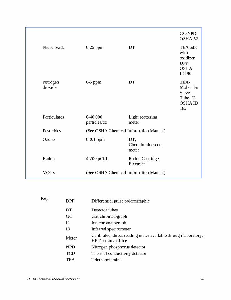
OSHA Technical Manual Section III 56
GC/NPD
OSHA-52
Nitric oxide 0-25 ppm DT TEA tube
with
oxidizer,
DPP
OSHA
ID190
Nitrogen
dioxide
0-5 ppm DT TEA-
Molecular
Sieve
Tube, IC
OSHA ID
182
Particulates 0-40,000
particles/cc
Light scattering
meter
Pesticides (See OSHA Chemical Information Manual)
Ozone 0-0.1 ppm DT,
Chemiluminescent
meter
Radon 4-200 pCi/L Radon Cartridge,
Electrect
VOC's (See OSHA Chemical Information Manual)
Key:
DPP Differential pulse polarographic
DT Detector tubes
GC Gas chromatograph
IC Ion chromatograph
IR Infrared spectrometer
Meter Calibrated, direct reading meter available through laboratory,
HRT, or area office
NPD Nitrogen phosphorus detector
TCD Thermal conductivity detector
TEA Triethanolamine
OSHA Technical Manual Section III 57
NOTE: Referenced OSHA procedures can be found in the OSHA Analytical Methods
Manual or the OSHA Chemical Information Manual. See individual manufacturer's
literature for information on interferences to the screening or sampling method.

OSHA Technical Manual Section III 58
SECTION III: CHAPTER 3
VENTILATION INVESTIGATION
Contents:
I. Introduction
II. Health Effects
III. Standards and Codes
IV. Investigation Guidelines
V. Prevention and Control
VI. Bibliography
Appendix III:3-1. Ventilation Primer
Appendix III:3-2. Glossary
Appendix III:3-3. OSHA and Consensus Standards
Appendix III:3-4. Troubleshooting an Exhaust System--Some Helpful Hints
For problems with accessibility in using figures and illustrations in this document, please contact
the
Office of Science and Technology Assessment at (202) 693-2095.
I. INTRODUCTION.
Industrial ventilation generally involves the use of supply and exhaust ventilation to
control emissions, exposures, and chemical hazards in the workplace. Traditionally,
nonindustrial ventilation systems commonly known as heating, ventilating, and air-
conditioning (HVAC) systems were built to control temperature, humidity, and odors.
1. Ventilation may be deficient in:
confined spaces;
facilities failing to provide adequate maintenance of ventilation
equipment;
facilities operated to maximize energy conservation;
windowless areas; and
areas with high occupant densities.
Any ventilation deficiency must be verified by measurement.
2. There are five basic types of ventilation systems:
1. dilution and removal by general exhaust;
2. local exhaust (see Figure III:3-1);

OSHA Technical Manual Section III 59
3. makeup air (or replacement);
4. HVAC (primarily for comfort); and
5. recirculation systems.
FIGURE III:3-1. COMPONENTS OF A LOCAL EXHAUST SYSTEM.
3. Ventilation systems generally involve a combination of these types of systems.
For example, a large local exhaust system may also serve as a dilution system,
and the HVAC system may serve as a makeup air system (see Appendix III:3-1
for a primer and Appendix III:3-2 for an explanation of these terms).
II. HEALTH EFFECTS.
Inadequate or improper ventilation is the cause of about half of all indoor air quality
(IAQ) problems in nonindustrial workplaces (see Section III, Chapter 2, Indoor Air
Quality). This section of the manual addresses ventilation in commercial buildings and
industrial facilities.
A. INDOOR AIR CONTAMINANTS include but are not limited to particulates,
pollen, microbial agents, and organic toxins. These can be transported by the
ventilation system or originate in the following parts of the ventilation system:
wet filters;
wet insulation;
wet undercoil pans;
cooling towers; and
evaporative humidifiers.
People exposed to these agents may develop signs and symptoms related to
"humidifier fever," "humidifier lung," or "air conditioner lung." In some cases,
indoor air quality contaminants cause clinically identifiable conditions such as
occupational asthma, reversible airway disease, and hypersensitivity pneumonitis.
B. VOLATILE ORGANIC AND REACTIVE CHEMICALS (for example,
formaldehyde) often contribute to indoor air contamination. The facility's

OSHA Technical Manual Section III 60
ventilation system may transport reactive chemicals from a source area to other
parts of the building. Tobacco smoke contains a number of organic and reactive
chemicals and is often carried this way. In some instances the contaminant source
may be the outside air. Outside air for ventilation or makeup air for exhaust
systems may bring contaminants into the workplace (e.g., vehicle exhaust,
fugitive emissions from a neighboring smelter).
See Section III, Chapter 2, Indoor Air Quality, for a discussion of common
indoor-air contaminants and their biological effects.
III. STANDARDS AND CODES.
. CONSENSUS STANDARDS. Appendix III:3-3 is a compilation of OSHA and
industry consensus standards. Foremost are those recommended by the Air
Movement and Control Association (AMCA), the American Society of Heating,
Refrigerating, and Air-Conditioning Engineers (ASHRAE), the American
National Standards Institute (ANSI), the Sheet Metal and Air Conditioning
Contractors National Association (SMACNA), the National Fire Protection
Association (NFPA), and the American Conference of Governmental Industrial
Hygienists (ACGIH). AMCA is a trade association that has developed standards
and testing procedures for fans. ASHRAE is a society of heating and air
conditioning engineers that has produced, through consensus, a number of
standards related to indoor air quality, filter performance and testing, and HVAC
systems. ANSI has produced several important standards on ventilation, including
ventilation for paintspray booths, grinding exhaust hoods, and open-surface tank
exhausts. Four ANSI standards were adopted by OSHA in 1971 and are codified
in 29 CFR 1910.94; these standards continue to be important as guides to design.
ANSI has recently published a new standard for laboratory ventilation (ANSI
Z9.5). SMACNA is an association representing sheet metal contractors and
suppliers. It sets standards for ducts and duct installation. NFPA has produced a
number of recommendations (which become requirements when adopted by local
fire agencies), e.g., NFPA 45 lists a number of ventilation requirements for
laboratory fume hood use. The ACGIH has published widely used guidelines for
industrial ventilation.
A. OSHA REGULATIONS. Ventilation criteria or standards are included in OSHA
regulatory codes for job- or task-specific worker protection (see Appendix III:3-
3). In addition, many OSHA health standards include ventilation requirements.
The four standards in 29 CFR 1910.94 deal with local exhaust systems, and
OSHA's construction standards (29 CFR 1926) contain ventilation standards for
welding. OSHA's compliance policy regarding violation of ventilation standards
is set forth in the Field Inspection Reference Manual.
IV. INVESTIGATION GUIDELINES.

OSHA Technical Manual Section III 61
. INVESTIGATION PHASES. Workplace investigations of ventilation systems
may be initiated by worker complaints of possible overexposures to air
contaminants, possible risk of fire or explosion from flammable gas or vapor
levels at or near the lower explosive limit (LEL), or indoor air quality complaints.
The second phase of the investigation involves an examination of the ventilation
system's physical and operating characteristics.
A. FAULTY VENTILATION CONDITIONS AND CAUSES. Common faulty
ventilation conditions and their probable causes are listed in Table III:3-1.
Specific points to consider during any investigation of a ventilation system
include emission source, air behavior, and employee involvement. Points that
should be included in a review of operational efficacy are shown in Table III:3-2.
Appendix III:3-4 contains information on points to be checked in a troublesome
exhaust system.
TABLE III:3-1. COMMON VENTILATION CONDITIONS AND CAUSES
Condition
Possible cause(s)
Worker complaints, improper use of system,
nonuse of system, alteration of system by
employees.
The hood interferes with work
The hood provides poor control of
contaminants.
Excessive employee exposures although
flow volumes and capture velocities are at
design levels.
Employee work practices need
improvement.
The ventilation system interferes with work
or worker productivity and leads workers to
bypass the system.
Employee training is not adequate.
Design of system is poor.
Constant plugging of duct. Plugged ducts occur when transport velocity
is inadequate or when vapor condenses in
the duct, wets particles, and causes a build-
up of materials.
These problems are caused by poor design,
open access doors close to the fan, fan
problems, or other problems.
Reduced capture velocities or excessive
fugitive emissions.
The cause of these conditions is usually
reduced flow rate, unless the process itself
has changed.
Reduced flow rate occurs in the following
situations:
plugged or dented ducts
slipping fan belts
open access doors

OSHA Technical Manual Section III 62
holes in ducts, elbows
closed blast gate to branch, or opened
blast gates to other branches, or
corroded and stuck blast gates
fan turning in reverse direction (This
can occur when lead wires are
reversed and cause the motor and fan
to turn backwards. Centrifugal fans
turning backwards may deliver up to
only 50% of rated capacity.)
worn out fan blades
additional branches or hoods added
to system since initial installation, or
clogged air cleaner.
TABLE III:3-2. PROBLEM CHARACTERIZATION
Emission source
Where are all emission sources or potential emission sources located?
Which emission sources actually contribute to exposure?
What is the relative contribution of each source to exposure?
Characterization of each contributor:
- chemical composition
- temperature
- rate of emission
- direction of emission
- initial emission velocity
- pattern of emission (continuous or intermittent)
- time intervals of emission
- mass of emitted material
Air behavior
Air temperature
Air movement (direction, velocity)
Mixing potential
Supply and return flow conditions, to include pressure differences between space
and surrounding areas
Sources of tempered and untempered make-up air
Air changes per hour

OSHA Technical Manual Section III 63
Influence of existing HVAC systems
Effects of wind speed and direction
Effects of weather and season
Employee
Worker interaction with emission source
Worker exposure levels
Worker location
Worker education, training, cooperation
C. BASIC TESTING EQUIPMENT might include:
o smoke tubes
o velometers, anemometers:
- swinging vane anemometer
- thermal or hot-wire anemometer
o pressure-sensing devices:
- U-tube or electronic manometers
- Pitot tube
- thermal (thermal and swinging vane instruments measure static
pressure indirectly)
- aneroid ("bellows") gauges
o noise-monitoring equipment
o measuring tapes
o other: rags, flashlight, mirror, tachometer
o combustible gas meter or oxygen meter
o tubes for CO, CO2, formaldehyde, etc.
D. DOCUMENTATION. The characteristics of the ventilation system that must be
documented during an investigation include equipment operability, physical
measurements of the system, and use practices.
E. EQUIPMENT OPERABILITY. Before taking velocity or pressure measurements, note
and record the operating status of the equipment. For example, are filters loaded or clean?
Are variable-flow devices like dampers, variable-frequency drives, or inlet vanes in use?
Are make-up units operating? Are system blueprints available?

OSHA Technical Manual Section III 64
F. MEASUREMENTS.
1. Duct diameters are measured to calculate duct areas. Inside duct diameter is the
most important measurement, but an outside measurement is often sufficient for a
sheet metal duct. To measure the duct, the tape should be thrown around the duct
to obtain the duct circumference, and the number should be divided by (3.142) to
obtain the diameter of the duct.
2. Hood and duct dimensions can be estimated from plans, drawings, and
specifications. Measurements can be made with measuring tape. If a duct is
constructed of 2½ or 4-foot sections, the sections can be counted (elbows and tees
should be included in the length).
3. Hood-face velocities outside the hood or at the hood face can be estimated with
velometers, smoke tubes, and swinging-vane anemometers, all of which are
portable, reliable, and require no batteries.
a. The minimum velocity that can be read by an anemometer is 50 feet per minute
(fpm). The meter should always be read in the upright position, and only the
tubing supplied with the equipment should be used.
b. Anemometers often cannot be used if the duct contains dust or mist because air
must actually pass through the instrument for it to work. The instrument requires
periodic cleaning and calibration at least once per year. Hot-wire anemometers
should not be used in airstreams containing aerosols.
c. Hood-face velocity measurement involves the following steps:
mark off imaginary areas;
measure velocity at center of each area; and
average all measured velocities.
d. Smoke is useful for measuring face velocity (see Figure III:3-2) because it is
visible. Nothing convinces management and employees more quickly that the
ventilation is not functioning properly than to show smoke drifting away from the
hood, escaping the hood, or traveling into the worker's breathing zone. Smoke can
be used to provide a rough estimate of face velocity:
FIGURE III:3-2. USE OF SMOKE TO DEMONSTRATE AIR FLOW.

OSHA Technical Manual Section III 65
Velocity = Distance/Time , or
V =
D
T
Squeeze off a quick burst of smoke. Time the smoke plume's travel over a two-
foot distance. Calculate the velocity in feet per minute. For example, if it takes
two seconds for the smoke to travel two feet, the velocity is 60 fpm.
4. Hood static pressures (SPH) should be measured about 4-6 duct diameters
downstream in a straight section of the hood take-off duct. The measurement can
be made with a pitot tube or by a static pressure tap into the duct sheet metal (see
Figure III:3-3).
FIGURE III:3-3. USE OF STATIC PRESSURE TAP INTO DUCT TO
MEASURE HOOD STATIC PRESSURE.
a. Pressure gauges come in a number of varieties, the simplest being the U-tube
manometer.
b. Inclined manometers offer greater accuracy and greater sensitivity at low
pressures than U-tube manometers. However, manometers rarely can be used for
velocities less than 800 fpm (i.e. velocity pressures less than 0.05" w.g.). Aneroid-
type manometers use a calibrated bellows to measure pressures. They are easy to
read and portable but require regular calibration and maintenance.
5. Duct velocity measurements may be made directly (with velometers and
anemometers) or indirectly (with manometers and pitot tubes) using duct velocity
pressure.
a. Air flow in industrial ventilation ducts is almost always turbulent, with a small,
nonmoving boundary layer at the surface of the duct.
b. Because velocity varies with distance from the edge of the duct, a single
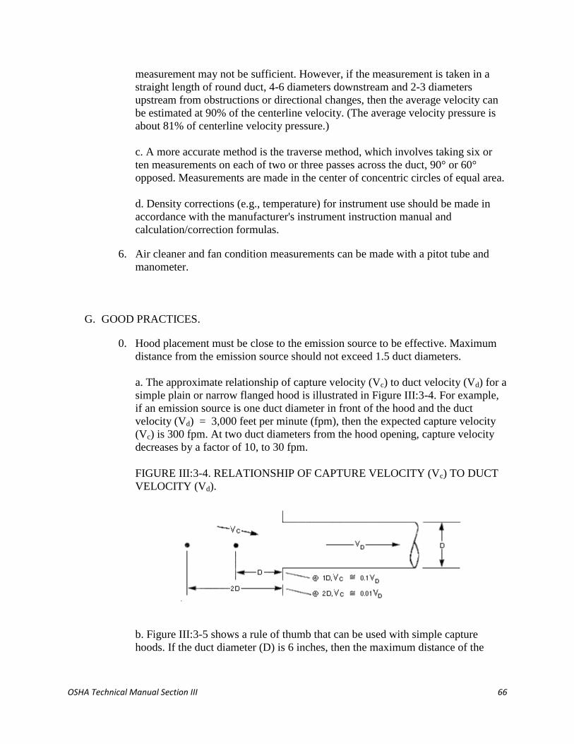
OSHA Technical Manual Section III 66
measurement may not be sufficient. However, if the measurement is taken in a
straight length of round duct, 4-6 diameters downstream and 2-3 diameters
upstream from obstructions or directional changes, then the average velocity can
be estimated at 90% of the centerline velocity. (The average velocity pressure is
about 81% of centerline velocity pressure.)
c. A more accurate method is the traverse method, which involves taking six or
ten measurements on each of two or three passes across the duct, 90° or 60°
opposed. Measurements are made in the center of concentric circles of equal area.
d. Density corrections (e.g., temperature) for instrument use should be made in
accordance with the manufacturer's instrument instruction manual and
calculation/correction formulas.
6. Air cleaner and fan condition measurements can be made with a pitot tube and
manometer.
G. GOOD PRACTICES.
0. Hood placement must be close to the emission source to be effective. Maximum
distance from the emission source should not exceed 1.5 duct diameters.
a. The approximate relationship of capture velocity (Vc) to duct velocity (Vd) for a
simple plain or narrow flanged hood is illustrated in Figure III:3-4. For example,
if an emission source is one duct diameter in front of the hood and the duct
velocity (Vd) = 3,000 feet per minute (fpm), then the expected capture velocity
(Vc) is 300 fpm. At two duct diameters from the hood opening, capture velocity
decreases by a factor of 10, to 30 fpm.
FIGURE III:3-4. RELATIONSHIP OF CAPTURE VELOCITY (Vc) TO DUCT
VELOCITY (Vd).
b. Figure III:3-5 shows a rule of thumb that can be used with simple capture
hoods. If the duct diameter (D) is 6 inches, then the maximum distance of the

OSHA Technical Manual Section III 67
emission source from the hood should not exceed 9 in. Similarly, the minimum
capture velocity should not be less than 50 fpm.
FIGURE III:3-5. RULE OF THUMB FOR SIMPLE CAPTURE HOODS:
MAXIMUM CAPTURE DISTANCE SHOULD NOT BE MORE THAN 1.5
TIMES THE DUCT DIAMETER.
c. Figure III:3-6 provides a guide for determining an effective flange width.
FIGURE III:3-6. EFFECTIVE FLANGE WIDTH (W).
1. System effect loss, which occurs at the fan, can be avoided if the necessary
ductwork is in place.
a. Use of the six-and-three rule ensures better design by providing for a minimum
loss at six diameters of straight duct at the fan inlet and a minimum loss at three
diameters of straight duct at the fan outlet (Figure II:3-7).
FIGURE III:3-7. AN ILLUSTRATION OF THE SIX-AND-THREE
RULE.

OSHA Technical Manual Section III 68
b. System effect loss is significant if any elbows are connected to the fan at inlet
or outlet. For each 2½ diameters of straight duct between the fan inlet and any
elbow, CFM loss will be 20%.
2. Stack height should be 10 ft higher than any roof line or air intake located within
50 ft of the stack (Figure III:3-8). For example, a stack placed 30 ft away from an
air intake should be at least 10 ft higher than the center of the intake.
FIGURE III:3-8. MINIMUM STACK HEIGHT IN RELATION TO
IMMEDIATE ROOF LINE OR CENTER OF ANY AIR INTAKE ON THE
SAME ROOF.
3. Ventilation system drawings and specifications usually follow standard forms and
symbols, e.g., as described in the Uniform Construction Index (UCI).
a. Plan sections include electrical, plumbing, structural, or mechanical drawings
(UCI, Section 15). The drawings come in several views: plan (top), elevation
(side and front), isometric, or section.
b. Elevations (side and front views) give the most detail. An isometric drawing is
one that illustrates the system in three dimensions. A sectional drawing provides
duct or component detail by showing a cross-section of the component.
c. Drawings are usually drawn to scale. (Check dimensions and lengths with a
ruler or a scale to be sure that this is the case. For example, 1/8 inch on the sheet

OSHA Technical Manual Section III 69
may represent one foot on the ground.) Good practices to follow when reviewing
plans and specifications are listed in Table III:3-3.
TABLE III:3-3. GOOD PRACTICES FOR
REVIEWING PLANS AND SPECIFICATIONS
Investigate the background and objectives of the project.
Understand the scope of the project. What is to be included and
why?
Look for conciseness and precision. Mark ambiguous phrases,
"legalese," and repetition.
Do the specifications spell out exactly what is wanted? What is
expected?
Do plans and specifications adhere to appropriate codes,
standards, requirements,policies, and do they recommend good
practice as established by the industry?
Will the designer be able to design, or the contractor to build,
the system from the plans and specifications?
Will the project meet OSHA requirements if it is built as
proposed?
V. PREVENTION AND CONTROL.
A well-designed system and a continuing preventive maintenance program are key
elements in the prevention and control of ventilation system problems.
A. ELEMENTS OF A GOOD MAINTENANCE PROGRAM.
PUT IT ON PAPER
B.
1. Establish a safe place to file drawings, specifications, fan curves,
operating instructions, and other papers generated during design,
construction, and testing.
2. Establish a program of periodic inspection.
a. The types and frequencies of inspections depend on the operation of the
system and other factors.
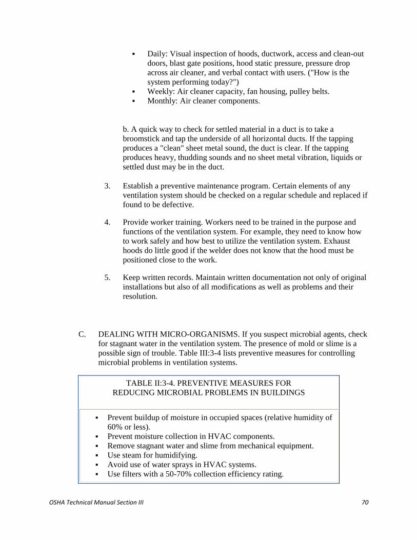
OSHA Technical Manual Section III 70
Daily: Visual inspection of hoods, ductwork, access and clean-out
doors, blast gate positions, hood static pressure, pressure drop
across air cleaner, and verbal contact with users. ("How is the
system performing today?")
Weekly: Air cleaner capacity, fan housing, pulley belts.
Monthly: Air cleaner components.
b. A quick way to check for settled material in a duct is to take a
broomstick and tap the underside of all horizontal ducts. If the tapping
produces a "clean" sheet metal sound, the duct is clear. If the tapping
produces heavy, thudding sounds and no sheet metal vibration, liquids or
settled dust may be in the duct.
3. Establish a preventive maintenance program. Certain elements of any
ventilation system should be checked on a regular schedule and replaced if
found to be defective.
4. Provide worker training. Workers need to be trained in the purpose and
functions of the ventilation system. For example, they need to know how
to work safely and how best to utilize the ventilation system. Exhaust
hoods do little good if the welder does not know that the hood must be
positioned close to the work.
5. Keep written records. Maintain written documentation not only of original
installations but also of all modifications as well as problems and their
resolution.
C. DEALING WITH MICRO-ORGANISMS. If you suspect microbial agents, check
for stagnant water in the ventilation system. The presence of mold or slime is a
possible sign of trouble. Table III:3-4 lists preventive measures for controlling
microbial problems in ventilation systems.
TABLE II:3-4. PREVENTIVE MEASURES FOR
REDUCING MICROBIAL PROBLEMS IN BUILDINGS
Prevent buildup of moisture in occupied spaces (relative humidity of
60% or less).
Prevent moisture collection in HVAC components.
Remove stagnant water and slime from mechanical equipment.
Use steam for humidifying.
Avoid use of water sprays in HVAC systems.
Use filters with a 50-70% collection efficiency rating.

OSHA Technical Manual Section III 71
Find and discard microbe-damaged furnishings and equipment.
Provide regular preventive maintenance.
D. VOLATILE ORGANIC OR REACTIVE CHIICALS. If an organic or reactive
chemical (e.g., formaldehyde) is believed to be the primary agent in an IAQ
problem, potential controls to consider include additional dilution ventilation,
removal or isolation of the offending material, and the transfer of sensitized
employees.
E. TOBACCO SMOKE IN AIR. OSHA has published a proposed rule for IAQ
(including tobacco smoke in the workplace), and this rulemaking is likely to be
completed in the near future. Smoking policies should include provisions for
dedicated smoking areas. Dedicated smoking areas should be configured so that
migration of smoke into nonsmoking areas will not occur. Such areas should:
have floor-to-ceiling walls of tight construction;
be under negative pressure relative to adjacent areas; AND
be exhausted outside the building and not recirculated.
For more information on investigation of complaints, CSHO's should consult the
NIOSH Guidance for Indoor Air Quality Investigation and the EPA guide
Building Air Quality (1991).
VI.
VII. BIBLIOGRAPHY.
American Conference of Governmental Industrial Hygienists (ACGIH). 1988. Industrial
Ventilation, a Manual of Recommended Practice. 20th ed. Cincinnati, OH: American Conference
of Governmental Industrial Hygienists.
Air Movement and Control Association (AMCA). 1988. AMCA Publication One. Arlington
Heights, IL: Air Movement and Control Association.
American Society of Heating, Refrigerating, and Air-Conditioning Engineers (ASHRAE).
Handbooks and Standards. Atlanta, GA: American Society of Heating, Refrigerating, and Air-
Conditioning Engineers.
Sheet Metal and Air Conditioning Contractors National Association (SMACNA). SMACNA
Publications. Arlington, VA: Sheet Metal and Air Conditioning Contractors National
Association.
American National Standards Institute (ANSI) Standards:
Z9.1 - Open Surface Tanks Operation

OSHA Technical Manual Section III 72
Z9.2 - Fundamentals Covering the Design and Operation of Local Exhaust Systems
Z9.3 - Design, Construction, and Ventilation of Spray Finishing Operations
Z9.4 - Ventilation and Safe Practice of Abrasive Blasting Operations
Z9.5 - Laboratory Ventilation. Fairfax, VA: American Industrial Hygiene Association.
Burgess, W. A. et al. 1989. Ventilation and Control of the Work Environment. New York: Wiley
Interscience.
Burton, D. J. 1989. Industrial Ventilation Workbook. Salt Lake City, UT: IVE, Inc.
Burton, D. J. 1990. Indoor Air Quality Workbook.Salt Lake City, UT: IVE, Inc.
Jorgensen, R. et al. 1983. Fan Engineering. 8th ed. Buffalo, NY: Buffalo Forge Co.
Homeon, W. C. L. 1963. Plant and Process Ventilation. New York: Industrial Press.
National Institute for Occupational Safety and Health (NIOSH). 1987. Guidance for Indoor Air
Quality Investigations. Cincinnati: NIOSH.
OSHA Field Operations Manual. 1992. OSHA Instruction CPL 2.45B. Washington, D.C.: U.S.
Government Printing Office.
U.S. Environmental Protection Agency (EPA). 1991. Building Air Quality.
APPENDIX III:3-1. VENTILATION PRIMER
SELECTION Before an appropriate ventilation system can be selected, the employer should
study emission sources, worker behavior, and air movement in the area. In some cases the
employer may wish to seek the services of an experienced professional ventilation engineer to
assist in the data gathering. Table III:3-5 shows factors to consider when selecting a ventilation
system. Combinations of controls are often employed for HVAC purposes.
TABLE III:3-5. SELECTION CRITERIA FOR GENERAL AND LOCAL EXHAUST
SYSTEMS
General exhaust ventilation (dilution ventilation) is appropriate when:
Emission sources contain materials of relatively low hazard. (The degree of hazard
is related to toxicity, dose rate, and individual susceptibility);
Emission sources are primarily vapors or gases, or small, respirable-size aerosols
(those not likely to settle);
Emissions occur uniformly;
Emissions are widely dispersed;
Moderate climatic conditions prevail;
Heat is to be removed from the space by flushing it with outside air;

OSHA Technical Manual Section III 73
Concentrations of vapors are to be reduced in an enclosure; and
Portable or mobile emission sources are to be controlled.
Local exhaust ventilating is appropriate when:
Emission sources contain materials of relatively high hazard;
Emitted materials are primarily larger-diameter particulates (likely to settle);
Emissions vary over time;
Emission sources consist of point sources;
Employees work in the immediate vicinity of the emission source;
The plant is located in a severe climate; and
Minimizing air turnover is necessary.
GENERAL EXHAUST (DILUTION) VENTILATION SYSTEMS General exhaust ventilation,
also called dilution ventilation, is different from local exhaust ventilation because instead of
capturing emissions at their source and removing them from the air, general exhaust ventilation
allows the contaminant to be emitted into the workplace air and then dilutes the concentration of
the contaminant to an acceptable level (e.g., to the PEL or below). Dilution systems are often
used to control evaporated liquids.
To determine the correct volume flow rate for dilution (Qd), it is necessary to estimate the
evaporation rate of the contaminant (qd) according to the following equation:
qd = (387) (lbs)
(MW)(min)(d)
where: qd = evaporation rate in acfm
387 = volume in cubic feet formed by the evaporation of one lb-mole of
a substance, e.g., a solvent
MW = molecular weight of emitted material
lbs = lbs of material evaporated
min = time of evaporation
d = density correction factor
The appropriate dilution volume flow rate for toxics is:
Qd = (qd)(Km)(10
6)
Ca

OSHA Technical Manual Section III 74
where:
Qd =
volume flow rate of air, in acfm
qd =
evaporation rate, in acfm
Km =
mixing factor to account for poor or random mixing
(Note: Km = 2 to 5; Km = 2 is optimum)
Ca =
acceptable airborne concentration of the material (typically half of the
PEL).
The number of air changes per hour is the number of times one volume of air is replaced in the
space per hour. In practice, replacement depends on mixing efficiency. When using dilution
ventilation:
position exhausts as close to emission sources as possible;
use auxiliary fans for mixing;
make sure employees are upwind of the dilution zone; and
add make-up air where it will be most effective.
LOCAL EXHAUST VENTILATION SYSTEMS A typical local exhaust ventilation system is
composed of five parts: fans, hoods, ducts, air cleaners, and stacks. Local exhaust ventilation is
designed to capture an emitted contaminant at or near its source, before the contaminant has a
chance to disperse into the workplace air.
FAN SELECTION To choose the proper fan for a ventilation system, this information must be
known:
air volume to be moved;
fan static pressure;
type and concentration of contaminants in the air (because this affects the fan type and
materials of construction); and
the importance of noise as a limiting factor.
Once this information is available, the type of fan best suited for the system can be chosen. Many
different fans are available, although they all fall into one of two classes: axial flow fans and
centrifugal fans. For a detailed explanation of fans, see the ACGIH Industrial Ventilation
Manual.
HOODS The hood captures, contains, or receives contaminants generated at an emission source.
The hood converts duct static pressure to velocity pressure and hood entry losses (e.g., slot and
duct entry losses).
Hood entry loss (He) is calculated according to the following equation:

OSHA Technical Manual Section III 75
He = (K)(VP) = |SPh |= VP
where:
K =
loss factor
VP =
velocity pressure in duct
|SPh| =
absolute static pressure about 5 duct diameters down the duct from the
hood.
A hood's ability to convert static pressure to velocity pressure is given by the coefficient of entry
(Ce), as follows:
Ce = Qideal
= √ VP
= √ 1
Qactual SPh 1 + K
where: K = loss factor
VP
=
velocity
pressure in
duct
SP
h =
static
pressure
To minimize air-flow requirements, the operation should be enclosed as much as possible, either
with a ventilated enclosure, side baffles, or curtains. This helps both to contain the material and
to minimize the effect of room air
When using a capture or receiving hood, the hood should be located as close to the contaminant
source as possible. Reducing the amount of contaminants generated or released from the process
reduces ventilation requirements.
The hood should be designed to achieve good air distribution into the hood openings so that all
the air drawn into the hood helps to control contaminants. Avoid designs that require that the
velocities through some openings be very high in order to develop the minimum acceptable
velocity through other openings or parts of the hood.
The purpose of most ventilation systems is to prevent worker inhalation of contaminants. For this
reason, the hood should be located so that contaminants are not drawn through the worker's
breathing zone. This is especially important where workers lean over an operation such as an
open-surface tank or welding bench.
OSHA Technical Manual Section III 76
Hoods must meet the design criteria in the ACGIH Industrial Ventilation Manual or applicable
OSHA standards. Most hood design recommendations account for cross-drafts that interfere with
hood operation. Strong cross-drafts can easily reduce a hood's effectiveness by 75%. Standard
hood designs may not be adequate to contain highly toxic materials.
The hood should be designed to cause minimum interference with the performance of work.
Positioning access doors inside an enclosure that must be opened and closed often means that in
practice the doors will be left open, and locating capture hoods too close to the process for the
worker's convenience often means that the hood will be disassembled and removed. Hoods
should never increase the likelihood of mechanical injury by interfering with a worker's freedom
to move around machinery.
Two common misconceptions about hoods that are a part of local exhaust systems are:
Hoods draw air from a significant distance away from the hood opening, and therefore
they can control contaminants released some distance away. It is easy to confuse a fan's
ability to blow a jet of air with its ability to draw air into a hood. Hoods must be close to
the source of contamination to be effective.
Heavier-than-air vapors tend to settle to the workroom floor and therefore can be
collected by a hood located there. A small amount of contaminant in the air (1,000 ppm
means 1,000 parts of contaminant plus 999,000 parts of air) has a resulting density close
to that of air, and random air currents will disperse the material throughout the room.
DUCTS Air flows turbulently through ducts at between 2,000-6,000 feet per minute (fpm). Ducts
can be made of galvanized metal, fiberglass, plastic, and concrete. Friction losses vary according
to ductwork type, length of duct, velocity of air, duct area, density of air, and duct diameter.
AIR CLEANERS The design of the air cleaner depends on the degree of cleaning required.
Regular maintenance of air cleaners increases their efficiency and minimizes worker exposure.
Different types of air cleaners are made to remove particulates (e.g., precipitators, cyclones, etc.)
and gases and vapors (e.g., scrubbers).
STACKS Stacks disperse exhaust air into the ambient environment. The amount of
reentrainment depends on exhaust volume, wind speed and direction, temperature, location of
intakes and exhausts, etc. When installing stacks:
Provide ample stack height (a minimum of 10 ft above adjacent rooflines or air intakes);
Place stack downwind of air intakes;
Provide a stack velocity of a minimum of 1.4 times the wind velocity;
Place the stack as far from the intake as possible (50 ft is recommended);
Place the stack at least 10 ft high on most roofs to avoid recirculation; and
Avoid rain caps if the air intake is within 50 ft of the stack.
MAKE-UP AIR SYSTEMS Exhaust ventilation systems require the replacement of exhausted
air. Replacement air is often called make-up air. Replacement air can be supplied naturally by
atmospheric pressure through open doors, windows, wall louvers, and adjacent spaces

OSHA Technical Manual Section III 77
(acceptable), as well as through cracks in walls and windows, beneath doors, and through roof
vents (unacceptable). Make-up air can also be provided through dedicated replacement air
systems. Generally, exhaust systems are interlocked with a dedicated make-up air system.
Other reasons for designing and providing dedicated make-up air systems are that they:
Avoid high-velocity drafts through cracks in walls, under doors, and through windows;
Avoid differential pressures on doors, exits, and windows; and
Provide an opportunity to temper the replacement air.
If make-up air is not provided, a slight negative pressure will be created in the room and air flow
through the exhaust system will be reduced.
HVAC (heating, ventilating, and air-conditioning) is a common term that can also include
cooling, humidifying or dehumidifying, or otherwise conditioning air for comfort and health.
HVAC also is used for odor control and the maintenance of acceptable concentrations of carbon
dioxide.
Air-conditioning has come to include any process that modifies the air for a work or living space:
heating or cooling, humidity control, and air cleaning. Historically, air-conditioning has been
used in industry to improve or protect machinery, products, and processes. The conditioning of
air for humans has become normal and expected. Although the initial costs of air conditioning
are high, annual costs may account only for about 1% to 5% of total annual operating expenses.
Improved human productivity, lower absenteeism, better health, and reduced housekeeping and
maintenance almost always make air-conditioning cost effective.
Mechanical air-handling systems can range from simple to complex. All distribute air in a
manner designed to meet ventilation, temperature, humidity, and air-quality requirements
established by the user. Individual units may be installed in the space they serve, or central units
can serve multiple areas.
HVAC engineers refer to the areas served by an air handling system as zones. The smaller the
zone, the greater the likelihood that good control will be achieved; however, equipment and
maintenance costs are directly related to the number of zones. Some systems are designed to
provide individual control of rooms in a multiple-zone system.
Both the provision and distribution of make-up air are important to the proper functioning of the
system. The correct amount of air should be supplied to the space. Supply registers should be
positioned to avoid disruption of emission and exposure controls and to aid dilution efforts.
Considerations in designing an air-handling system include volume flow rate, temperature,
humidity, and air quality. Equipment selected must be properly sized and may include:
outdoor air plenums or ducts
filters
supply fans and supply air systems

OSHA Technical Manual Section III 78
heating and cooling coils
humidity control equipment
supply ducts
distribution ducts, boxes, plenums, and registers
dampers
return air plenums
exhaust air provisions
return fans
controls and instrumentation
RECIRCULATION Although not generally recommended, recirculation is an alternative to air
exchanging. Where used, recirculation should incorporate air cleaners, a by-pass or auxiliary
exhaust system, regular maintenance and inspection, and devices to monitor system performance.
Key points to consider in the use of recirculation are shown in Table III:3-6.
TABLE III:3-6. RECIRCULATION CRITERIA
Protection of employees must be the primary design consideration.
The system should remove as much of the contaminant as can economically be
separated from exhaust air.
The system should not be designed simply to achieve PEL levels of exposure.
The system should never allow recirculation to significantly increase existing
exposures.
Recirculation should not be used if a carcinogen is present.
The system should have fail-safe features, e.g., warning devices on critical parts,
back-up systems.
Cleaning and filtering devices that ensure continuous and reliable collection of the
contaminant should be used.
The system should provide a by-pass or auxiliary exhaust system for use during
system failure.
The system should include feedback devices that monitor system performance, e.g.,
static pressure taps, particulate counters, amperage monitors.
The system should be designed not to recirculate air during equipment malfunction.
The employer should train employees in the use and operation of the system.
APPENDIX III:3-2. GLOSSARY
acfm Actual cubic feet per minute of gas flowing at existing temperature and pressure. (See also
scfm.)
ACH, AC/H (air changes per hour) The number of times air is replaced in an hour.

OSHA Technical Manual Section III 79
AIR DENSITY The weight of air in lbs per cubic foot. Dry standard air at T=68° F (20° C) and
BP = 29.92 in Hg (760 mm Hg) has a density of 0.075 lb/cu ft.
ANIOMETER A device that measures the velocity of air. Common types include the swinging
vane and the hot-wire anemometer.
AREA (A) The cross-sectional area through which air moves. Area may refer to the cross-
sectional area of a duct, a window, a door, or any space through which air moves.
ATMOSPHERIC PRESSURE The pressure exerted in all directions by the atmosphere. At sea
level, mean atmospheric pressure is 29.92 in Hg, 14.7 psi, 407 in w.g., or 760 mm Hg.
BRAKE HORSEPOWER (bhp) The actual horsepower required to move air through a
ventilation system against a fixed total pressure plus the losses in the fan. bhp=ahp × 1/eff, where
eff is fan mechanical efficiency.
BRANCH In a junction of two ducts, the branch is the duct with the lowest volume flow rate.
The branch usually enters the main at an angle of less than 90.
CANOPY HOOD (Receiving Hood) A one- or two-sided overhead hood that receives rising hot
air or gas.
CAPTURE VELOCITY The velocity of air induced by a hood to capture emitted contaminants
external to the hood.
COEFFICIENT OF ENTRY (Ce) A measure of the efficiency of a hood's ability to convert
static pressure to velocity pressure; the ratio of actual flow to ideal flow.
DENSITY CORRECTION FACTOR A factor applied to correct or convert dry air density of
any temperature to velocity pressure; the ratio of actual flow to ideal flow.
DILUTION VENTILATION (General Exhaust Ventilation) A form of exposure control that
involves providing enough air in the workplace to dilute the concentration of airborne
contaminants to acceptable levels.
ENTRY LOSS See Hood Entry Loss or Branch Entry Loss.
EVASE (pronounced eh-va-say) A cone-shaped exhaust stack that recaptures static pressure
from velocity pressure.
FAN A mechanical device that moves air and creates static pressure.
FAN LAWS Relationships that describe theoretical, mutual performance changes in pressure,
flow rate, rpm of the fan, horsepower, density of air, fan size, and sound power.
FAN CURVE A curve relating pressure and volume flow rate of a given fan at a fixed fan

OSHA Technical Manual Section III 80
speed (rpm).
FRICTION LOSS The static pressure loss in a system caused by friction between moving air
and the duct wall, expressed as in w.g./100 ft, or fractions of VP per 100 ft of duct (mm w.g./m;
Kpa/m).
GAUGE PRESSURE The difference between two absolute pressures, one of which is usually
atmospheric pressure.
GENERAL EXHAUST See Dilution Ventilation.
HEAD Pressure, e.g. "The head is 1 in w.g."
HOOD A device that encloses, captures, or receives emitted contaminants.
HOOD ENTRY LOSS (He) The static pressure lost (in inches of water) when air enters a duct
through a hood. The majority of the loss usually is associated with a vena contracta formed in the
duct.
HOOD STATIC PRESSURE (SPh) The sum of the duct velocity pressure and the hood entry
loss; hood static pressure is the static pressure required to accelerate air at rest outside the hood
into the duct at velocity.
HVAC (HEATING, VENTILATION, AND AIR CONDITIONING) SYSTEMS Ventilating
systems designed primarily to control temperature, humidity, odors, and air quality.
INDOOR AIR QUALITY (IAQ), SICK-BUILDING SYNDROME, TIGHT-BUILDING
SYNDROME The study, examination, and control of air quality related to temperature,
humidity, and airborne contaminants.
in. w.g. (inches of water) A unit of pressure. One inch of water is equal to 0.0735 in. of
mercury, or 0.036 psi. Atmospheric pressure at standard conditions is 407 in. w.g.
INDUSTRIAL VENTILATION (IV) The equipment or operation associated with the supply or
exhaust of air by natural or mechanical means to control occupational hazards in the industrial
setting.
LAMINAR FLOW (also Streamline Flow) Air flow in which air molecules travel parallel to all
other molecules; laminar flow is characterized by the absence of turbulence.
LOCAL EXHAUST VENTILATION An industrial ventilation system that captures and
removes emitted contaminants before dilution into the ambient air of the workplace.
LOSS Usually refers to the conversion of static pressure to heat in components of the
ventilation system, e.g., "the hood entry loss."
OSHA Technical Manual Section III 81
MAKE-UP AIR See Replacement and Compensating Air.
MANOMETER A device that measures pressure difference; usually a U-shaped glass tube
containing water or mercury.
MINIMUM TRANSPORT VELOCITY (MTV). The minimum velocity that will transport
particles in a duct with little settling; MTV varies with air density, particulate loading, and other
factors.
OUTDOOR AIR (OA) Outdoor air is the "fresh" air mixed with return air (RA) to dilute
contaminants in the supply air.
PITOT TUBE A device used to measure total and static pressures in an airstream.
PLENUM A low-velocity chamber used to distribute static pressure throughout its interior.
PRESSURE DROP The loss of static pressure across a point; for example, "the pressure drop
across an orifice is 2.0 in. w.g."
REPLACEMENT AIR (also, Compensating Air, Make-Up Air) Air supplied to a space to
replace exhausted air.
RETURN AIR Air that is returned from the primary space to the fan for recirculation.
scfm Standard cubic feet per minute. A measure of air flow at standard conditions, i.e., dry air
at 29.92 in. Hg (760 mm Hg) (gauge), 68° F (20° C).
SLOT VELOCITY The average velocity of air through a slot. Slot velocity is calculated by
dividing the total volume flow rate by the slot area (usually, Vs = 2,000 fpm).
STACK A device on the end of a ventilation system that disperses exhaust contaminants for
dilution by the atmosphere.
STANDARD AIR, STANDARD CONDITIONS Dry air at 68° F (20° C), 29.92 in Hg (760
mm Hg).
STATIC PRESSURE (SP) The pressure developed in a duct by a fan; the force in inches of
water measured perpendicular to flow at the wall of the duct; the difference in pressure between
atmospheric pressure and the absolute pressure inside a duct, cleaner, or other equipment; SP
exerts influence in all directions.
SUCTION PRESSURE (See Static Pressure.) An archaic term that refers to static pressure on
the upstream side of the fan.
TOTAL PRESSURE (TP) The pressure exerted in a duct, i.e., the sum of the static pressure and
the velocity pressure; also called Impact Pressure, Dynamic Pressure.

OSHA Technical Manual Section III 82
TRANSPORT VELOCITY See Minimum Transport Velocity.
TURBULENT FLOW Air flow characterized by transverse velocity components as well as
velocity in the primary direction of flow in a duct; mixing velocities.
VELOCITY (V) The time rate of movement of air; usually expressed as feet per minute.
VELOCITY PRESSURE (VP) The pressure attributed to the velocity of air.
VOLUME FLOW RATE (Q) Quantity of air flow in cfm, scfm, or acfm.
APPENDIX III:3-3. OSHA AND CONSENSUS STANDARDS
I. OSHA STANDARDS.
A. HEALTH-RELATED VENTILATION STANDARDS. This list includes some,
but not necessarily all, OSHA standards that address the control of employee
exposure to recognized contaminants.)
General industry
29 CFR 1910.94(a) Abrasive blasting
29 CFR 1910.94(b) Grinding, polishing and buffing operations
29 CFR 1910.94(d) Open surface tanks
29 CFR 1910.252(c)(2)(i)(a)
and (b); (c)(2)(ii)
Ventilation for general welding and cutting--General
29 CFR 1910.252(c)(3) Local exhaust hoods and booths
29 CFR 1910.252(c)(5)(ii) Fluorine compounds--Maximum allowable
concentration
29 CFR 1910.252(c)(12) Cutting of stainless steels
29 CFR 1910.1003 to .1016 Carcinogens
29 CFR 1910.1025(e)(5) Lead
29 CFR 1910.1027(f)(3) Cadmium
Construction
29 CFR 1926.57(a) Ventilation--General
29 CFR 1926.62(e)(3) Lead
29 CFR 1926.63(f)(4) Cadmium
29 CFR 1926.154(a)(1) Temporary heating devices--Ventilation
OSHA Technical Manual Section III 83
29 CFR 1926.353(e)(1) Ventilation and protection in welding, cutting and
heating--General welding, cutting, and heating
Maritime
29 CFR 1915.32(a)(2) Toxic cleaning solvents
29 CFR 1915.51(f)(1) Ventilation and protection in welding, cutting and
heating--General welding, cutting, and heating
29 CFR 1918.93(a)(1)(iii) Ventilation and atmospheric conditions
B. HEALTH-RELATED VENTILATION STANDARDS OTHER THAN
AIRFLOW. This list includes some, but not necessarily all, OSHA standards that
do not contain airflow requirements but are located in the health-related
ventilation standards.
General Industry
29 CFR 1910.94(a)(3)(i)(d) Abrasive blasting--Blasting cleaning
29 CFR 1910.94(a)(5) Abrasive blasting--Personal protective equipment
29 CFR 1910.94(a)(6) Abrasive blasting--Air supply and air compressors
29 CFR 1910.94(a)(7) Abrasive blasting--Operational procedures and general
safety
29 CFR 1910.94(d)(9) Open surface tanks--Personal protection
29 CFR 1910.94(d)(10) Open surface tanks--Special precautions for cyanide
29 CFR 1910.94(d)(11) Open surface tanks--Inspection, installation and
maintenance
29 CFR 1910.94(d)(12) Open surface tanks--Vapor degreasing tanks
C. FIRE AND EXPLOSION-RELATED VENTILATION STANDARDS. This list
includes some, but not necessarily all, OSHA standards that are intended to
prevent fire and explosions.
General industry
29 CFR 1910.94(c) Ventilation--Spray finishing operations
29 CFR 1910.103(b)(3)(ii)(b) Hydrogen--Gaseous hydrogen systems--Separate
buildings
29 CFR 1910.103(b)(3)(iii)(b) Hydrogen--Gaseous hydrogen systems--Special
rooms
29 CFR 1910.103(c)(3)(ii)(b) Hydrogen--Liquid hydrogen systems--Separate
buildings
OSHA Technical Manual Section III 84
29 CFR 1910.103(c)(3)(iii)(b) Hydrogen--Liquid hydrogen systems--Special
rooms
29 CFR 1910.104(b)(3)(xii) Oxygen--Bulk oxygen systems--Ventilation
29 CFR 1910.104(b)(8)(vii) Oxygen--Bulk oxygen systems--Venting
29 CFR 1910.106(d)(4)(iv) Flammable and combustible liquids--Container
and portable tank storage--Design and
construction of inside storage room--Ventilation
29 CFR 1910.106(e)(3)(v) Flammable and combustible liquids--Industrial
plants--Unit physical operations--Ventilation
29 CFR 1910.106(f)(2)(iii)(a) Flammable and combustible liquids--Bulk plants--
Building--Ventilation
29 CFR 1910.106(h)(3)(iii) Flammable and combustible liquids--Processing
plants--Processing building--Ventilation
29 CFR 1910.107(b)(5)(i) Spray finishing using flammable and combustible
materials--Spray booths--Dry type overspray
collectors
29 CFR 1910.107(d)(1) and (2) Spray finishing using flammable and combustible
materials--Ventilation--Conformance--General
29 CFR 1910.107(i)(9) Spray finishing using flammable and combustible
materials--Electrostatic hand spraying equipment-
-Ventilation
29 CFR 1910.108(b)(1) and (2) Dip tanks containing flammable combustible
liquids--Ventilation--Ventilation combined with
drying
29 CFR 1910.307 Hazardous (classified) locations
D. EXCEPTIONS TO 25% OF THE LEL FOR FIRE AND EXPLOSION-
RELATED STANDARDS. This list includes but is not limited to OSHA
standards that allow concentrations of flammable materials no greater than 10%
of the LEL.
Maritime
29 CFR 1915.12(a)(2) Precautions before entering--Flammable
atmospheres and residues
29 CFR 1915.13(a)(2) Cleaning and other cold work (flammable vapors)
29 CFR 1915.35(b)(1), (2), (3) Painting--Paints and tanks coatings dissolved in
highly volatile, toxic and/or flammable solvents
29 CFR 1915.36(a)(2) Flammable liquids ventilation
Construction

OSHA Technical Manual Section III 85
29 CFR 1926.803(i)(2) Compressed Air--Ventilation and air quality--
(Tunnels)
E. SPECIAL CONDITIONS STANDARDS. This list includes some but not
necessarily all OSHA standards that involve confined space operations and/or
high-hazard contaminants specifically designated in the standard.
General industry
29 CFR 1910.252(c)(2)(i)(c) Welding, cutting and brazing--Health protection and
ventilating--Ventilation for general welding and
cutting--General
29 CFR 1910.252(c)(4) Welding, cutting and brazing--Health protection and
ventilating--Ventilation in confined spaces
29 CFR 1910.252(c)(5)(i) Welding, cutting and brazing--Fluorine compounds
29 CFR 1910.252(c)(6)(i) Welding, cutting and brazing--Zinc--Confined
spaces
29 CFR 1910.252(c)(7)(i) Welding, cutting and brazing--Lead--Confined
spaces
29 CFR 1910.252(c)(8) Welding, cutting and brazing--Beryllium
29 CFR 1910.252(c)(9) Welding, cutting and brazing--Cadmium
29 CFR 1910.252(c)(10) Welding, cutting and brazing--Mercury
Construction
29 CFR 1926.154(a)(2) Temporary heating devices--Ventilation
29 CFR 1926.353(b)(1) Ventilation and protection in welding, cutting and
heating--Welding, cutting and heating in confined
spaces
29 CFR 1926.353(c)(1) and (2) Ventilation and protection in welding, cutting and
heating--Welding, cutting or heating of metals of
toxic significance
29 CFR 1926.800(k) Tunnels and shafts--Air quality and ventilation
Maritime
29 CFR 1915.12(b)(2) Precautions before entering--Toxic atmospheres and
residues
29 CFR 1915.12(c)(2) Precautions before entering--Oxygen deficient
atmospheres
29 CFR 1915.12(d) Precautions before entering--Exceptions
29 CFR 1915.34(a)(4) Mechanical paint removers--Power tools--(paint

OSHA Technical Manual Section III 86
dust)
29 CFR 1915.51(c)(3) Ventilation and protection in welding, cutting and
heating--Welding, cutting and heating confined
spaces
29 CFR 1915.51(d)(1) and (2) Ventilation and protection in welding, cutting and
heating--cutting or heating of metals of toxic
significance.
II. CONSENSUS STANDARDS.
Standard Source Title
Air filters
ASHRAE 52-76 ASHRAE Methods of Testing Air-Cleaning Devices Used in
General Ventilation for Removing Particulate Matter
Exhaust systems
ANSI Z33.1-1982
NFPA 91-1983
NFPA Installation of Blower and Exhaust Systems for Dust,
Stock, Vapor Removal or Conveying (1983)
ANSI Z9.2-1979 AIHA Fundamentals Governing the Design and Operation of
Local Exhaust Systems
ANSI Z9.1-1977 AIHA
ASHRAE
Practices for Ventilation and Operation of Open-
Surface Tanks
ANSI Z9.3-1964 ANSI Safety Code for Design, Construction, and Ventilation
of Spray Finishing Operations (reaffirmed 1971)
ANSI Z9.4-1979
ANSI Z9.4A-1981
ANSI Ventilation and Safe Practices of Abrasives Blasting
Operations
ANSI Z9.5-1992 AIHA Laboratory Ventilation
Fans
AMCA 99-83
ANSI/UL 507-1976
AMCA
UL
Standards Handbook Electric Fans (1977)
ASHRAE 51-75
AMCA 210-74
ASHRAE Laboratory Methods of Testing Fans for Rating
ANSI/ASHRAE
87.7-1983
ASHRAE Methods of Testing Dynamic Characteristics of
Propeller Fans--Aerodynamically Excited Fan
Vibrations and Critical Speeds
AMCA 210-74 AMCA Laboratory Methods of Testing Fans for Rating
Purposes
AMCA 99-2404-78 AMCA Drive Arrangement for Centrifugal Fans

OSHA Technical Manual Section III 87
AMCA 99-2406-83 AMCA Designation for Rotation and Discharge of Centrifugal
Fans
AMCA 99-2407-66 AMCA Motor Positions for Belt or Chain Drive Centrifugal
Fans
AMCA 99-2410-82 AMCA Drive Arrangement for Tubular Centrifugal Fans
Industrial duct
SMACNA SMACNA Round Industrial Duct Construction
SMACNA SMACNA Rectangular Industrial Duct Construction
Venting
NFPA 68 NFPA Guide for Explosion Venting
NFPA 204M NFPA Guide for Smoke and Heat Venting
SMACNA SMACNA Guide for Steel Stack Design and Construction (1983)
Ventilation
NFPA 96 NFPA Vapor Removal from Cooking Equipment (1984)
NFPA-88A, 88B NFPA Parking Structures (1979); Repair Garages (1979)
ASHRAE 62-1989 ASHARAE Ventilation for Acceptable Indoor Air Quality
ACGIH ACGIH Industrial Ventilation
III. SOURCES OF CONSENSUS STANDARDS.
Copies of the consensus standards are published and available directly from the organization
issuing the standard. A minimal fee is often required.
Source Organization
ACGIH American Conference of Governmental Industrial Hygienists
6500 Glenway Ave., Bldg. D-5
Cincinnati, OH 45211
AIHA American Industrial Hygiene Association
2700 Prosperity Ave., Suite 250
Fairfax, VA 22031-4319
AMCA Air Movement and Control Association
30 W. University Dr.
Arlington Heights, IL 60004
OSHA Technical Manual Section III 88
ANSI American National Standards Institute
1430 Broadway
New York, NY 10018
ASHRAE American Society of Heating, Refrigeration and Air-Conditioning
Engineers, Inc.
1791 Tullie Circle, N.E.,
Atlanta, GA 30329
NFPA National Fire Protection Association
Batterymarch Park
Quincy, MA 02269
SMACNA Sheet Metal and Air Conditioning Contractors' National Association
8224 Old Courthouse Rd.
Vienna, VA 22180
UL Underwriters Laboratories Inc.
333 Pfingsten Rd.
Northbrook, IL 60062
APPENDIX III:3-4. TROUBLESHOOTING AN EXHAUST SYSTEM--SOME HELPFUL
HINTS
Most of the following checks can be made by visual observation and do not require extensive
measurements.
If air flow is low in hoods, check:
Fan rotation (reversed polarity will cause fan to run backwards; a backward-running
centrifugal fan delivers only 30-50% of rated flow);
Fan RPM;
Slipping belt;
Clogged or corroded fan wheel and casing;
Clogged ductwork (high hood static pressure and low air flow may indicate restricted
ducts; open clean-out doors and inspect inside ducts);
Closed dampers in ductwork;
Clogged collector or air cleaning devices;
Weather cap too close to discharge stack (a 3/4 duct- diameter gap should exist between
cap and stack; weather caps are not recommended);
Poorly designed ductwork (short radius elbows); (branch entries enter main duct at sharp
angles); (duckwork diameter too small for the air-flow needed; and
Lack of make-up air (high negative pressures affect propeller fan system output; lack of
supplied make-up air causes high airflow velocities at doors and windows).
If air flow is satisfactory in a hood but contaminant control is poor, check:

OSHA Technical Manual Section III 89
Crossdrafts (from process air movements); (worker-cooling fans and air-supply systems);
(open doors and windows);
Capture velocity (work operation too far from hood opening);
Hood enclosure: (door, baffles, or sides may be open or removed); and
Hood type: (canopy hoods are inappropriate for toxic materials).

OSHA Technical Manual Section III 90
SECTION III: CHAPTER 4
HEAT STRESS
Contents:
I. Introduction
II. Heat Disorders and Health Effects
III. Investigation Guidelines
IV. Sampling Methods
V. Control
VI. Personal Protective Equipment
VII. Bibliography
Appendix III:4-1 Heat Stress: General Workplace Review
Appendix III:4-2 Heat Stress-Related Illness/Accident Follow-Up
Appendix III:4-3 Measurement of Wet Bulb Globe Temperature
For problems with accessibility in using figures and illustrations in this document, please contact
the
Office of Science and Technology Assessment at (202) 693-2095.
I. INTRODUCTION.
Operations involving high air temperatures, radiant heat sources, high humidity, direct
physical contact with hot objects, or strenuous physical activities have a high potential for
inducing heat stress in employees engaged in such operations. Such places include: iron
and steel foundries, nonferrous foundries, brick-firing and ceramic plants, glass products
facilities, rubber products factories, electrical utilities (particularly boiler rooms),
bakeries, confectioneries, commercial kitchens, laundries, food canneries, chemical
plants, mining sites, smelters, and steam tunnels.
Outdoor operations conducted in hot weather, such as construction, refining, asbestos
removal, and hazardous waste site activities, especially those that require workers to wear
semipermeable or impermeable protective clothing, are also likely to cause heat stress
among exposed workers.
A. CAUSAL FACTORS.
OSHA Technical Manual Section III 91
1. Age, weight, degree of physical fitness, degree of acclimatization,
metabolism, use of alcohol or drugs, and a variety of medical conditions
such as hypertension all affect a person's sensitivity to heat. However,
even the type of clothing worn must be considered. Prior heat injury
predisposes an individual to additional injury.
2. It is difficult to predict just who will be affected and when, because
individual susceptibility varies. In addition, environmental factors include
more than the ambient air temperature. Radiant heat, air movement,
conduction, and relative humidity all affect an individual's response to
heat.
B. DEFINITIONS.
1. The American Conference of Governmental Industrial Hygienists (1992)
states that workers should not be permitted to work when their deep body
temperature exceeds 38°C (100.4°F).
2. Heat is a measure of energy in terms of quantity.
3. A calorie is the amount of heat required to raise 1 gram of water 1°C
(based on a standard temperature of 16.5 to 17.5°C).
4. Conduction is the transfer of heat between materials that contact each
other. Heat passes from the warmer material to the cooler material. For
example, a worker's skin can transfer heat to a contacting surface if that
surface is cooler, and vice versa.
5. Convection is the transfer of heat in a moving fluid. Air flowing past the
body can cool the body if the air temperature is cool. On the other hand,
air that exceeds 35°C (95°F) can increase the heat load on the body.
6. Evaporative cooling takes place when sweat evaporates from the skin.
High humidity reduces the rate of evaporation and thus reduces the
effectiveness of the body's primary cooling mechanism.
7. Radiation is the transfer of heat energy through space. A worker whose
body temperature is greater than the temperature of the surrounding
surfaces radiates heat to these surfaces. Hot surfaces and infrared light
sources radiate heat that can increase the body's heat load.
8. Globe temperature is the temperature inside a blackened, hollow, thin
copper globe.
9. Metabolic heat is a by-product of the body's activity.
OSHA Technical Manual Section III 92
10. Natural wet bulb (NWB) temperature is measured by exposing a wet
sensor, such as a wet cotton wick fitted over the bulb of a thermometer, to
the effects of evaporation and convection. The term natural refers to the
movement of air around the sensor.
11. Dry bulb (DB) temperature is measured by a thermal sensor, such as an
ordinary mercury-in-glass thermometer, that is shielded from direct
radiant energy sources.
II. HEAT DISORDERS AND HEALTH EFFECTS.
A. HEAT STROKE occurs when the body's system of temperature regulation fails
and body temperature rises to critical levels. This condition is caused by a
combination of highly variable factors, and its occurrence is difficult to predict.
Heat stroke is a medical emergency. The primary signs and symptoms of heat
stroke are confusion; irrational behavior; loss of consciousness; convulsions; a
lack of sweating (usually); hot, dry skin; and an abnormally high body
temperature, e.g., a rectal temperature of 41°C (105.8°F). If body temperature is
too high, it causes death. The elevated metabolic temperatures caused by a
combination of work load and environmental heat load, both of which contribute
to heat stroke, are also highly variable and difficult to predict.
If a worker shows signs of possible heat stroke, professional medical treatment
should be obtained immediately. The worker should be placed in a shady area and
the outer clothing should be removed. The worker's skin should be wetted and air
movement around the worker should be increased to improve evaporative cooling
until professional methods of cooling are initiated and the seriousness of the
condition can be assessed. Fluids should be replaced as soon as possible. The
medical outcome of an episode of heat stroke depends on the victim's physical
fitness and the timing and effectiveness of first aid treatment.
Regardless of the worker's protests, no employee suspected of being ill from heat
stroke should be sent home or left unattended unless a physician has specifically
approved such an order.
B. HEAT EXHAUSTION. The signs and symptoms of heat exhaustion are
headache, nausea, vertigo, weakness, thirst, and giddiness. Fortunately, this
condition responds readily to prompt treatment. Heat exhaustion should not be
dismissed lightly, however, for several reasons. One is that the fainting associated
with heat exhaustion can be dangerous because the victim may be operating
machinery or controlling an operation that should not be left unattended;
moreover, the victim may be injured when he or she faints. Also, the signs and
symptoms seen in heat exhaustion are similar to those of heat stroke, a medical
emergency.
Workers suffering from heat exhaustion should be removed from the hot

OSHA Technical Manual Section III 93
environment and given fluid replacement. They should also be encouraged to get
adequate rest.
C. HEAT CRAMPS are usually caused by performing hard physical labor in a hot
environment. These cramps have been attributed to an electrolyte imbalance
caused by sweating. It is important to understand that cramps can be caused by
both too much and too little salt. Cramps appear to be caused by the lack of water
replenishment. Because sweat is a hypotonic solution (±0.3% NaCl), excess salt
can build up in the body if the water lost through sweating is not replaced. Thirst
cannot be relied on as a guide to the need for water; instead, water must be taken
every 15 to 20 minutes in hot environments.
Under extreme conditions, such as working for 6 to 8 hours in heavy protective
gear, a loss of sodium may occur. Recent studies have shown that drinking
commercially available carbohydrate-electrolyte replacement liquids is effective
in minimizing physiological disturbances during recovery.
D. HEAT COLLAPSE ("Fainting"). In heat collapse, the brain does not receive
enough oxygen because blood pools in the extremities. As a result, the exposed
individual may lose consciousness. This reaction is similar to that of heat
exhaustion and does not affect the body's heat balance. However, the onset of heat
collapse is rapid and unpredictable. To prevent heat collapse, the worker should
gradually become acclimatized to the hot environment.
E. HEAT RASHES are the most common problem in hot work environments.
Prickly heat is manifested as red papules and usually appears in areas where the
clothing is restrictive. As sweating increases, these papules give rise to a prickling
sensation. Prickly heat occurs in skin that is persistently wetted by unevaporated
sweat, and heat rash papules may become infected if they are not treated. In most
cases, heat rashes will disappear when the affected individual returns to a cool
environment.
F. HEAT FATIGUE. A factor that predisposes an individual to heat fatigue is lack
of acclimatization. The use of a program of acclimatization and training for work
in hot environments is advisable. The signs and symptoms of heat fatigue include
impaired performance of skilled sensorimotor, mental, or vigilance jobs. There is
no treatment for heat fatigue except to remove the heat stress before a more
serious heat-related condition develops.
III. INVESTIGATION GUIDELINES.
These guidelines for evaluating employee heat stress approximate those found in the
1992-1993 ACGIH publication, Threshold Limit Values for Chemical Substances and
Physical Agents and Biological Exposure Indices.
A. EMPLOYER AND EMPLOYEE INTERVIEWS.

OSHA Technical Manual Section III 94
1. The inspector will review the OSHA 200 Log and, if possible, the OSHA
101 forms for indications of prior heat stress problems.
2. Following are some questions for employer interviews: What type of
action, if any, has the employer taken to prevent heat stress problems?
What are the potential sources of heat? What employee complaints have
been made?
3. Following are some questions for employee interviews: What heat stress
problems have been experienced? What type of action has the employee
taken to minimize heat stress? What is the employer's involvement, i.e.,
does employee training include information on heat stress? (Appendix
III:4-1 lists factors to be evaluated when reviewing a heat stress situation,
and Appendix III:4-2 contains a follow-up checklist.)
B. WALKAROUND INSPECTION. During the walkaround inspection, the
investigator will: determine building and operation characteristics; determine
whether engineering controls are functioning properly; verify information
obtained from the employer and employee interviews; and perform temperature
measurements and make other determinations to identify potential sources of heat
stress. Investigators may wish to discuss any operations that have the potential to
cause heat stress with engineers and other knowledgeable personnel. The
walkaround inspection should cover all affected areas. Heat sources, such as
furnaces, ovens, and boilers, and relative heat load per employee should be noted.
C. WORK-LOAD ASSESSMENT.
1. Under conditions of high temperature and heavy workload, the CSHO
should determine the work-load category of each job (Table III:4-1 and
Figure III:4-1). Work-load category is determined by averaging metabolic
rates for the tasks and then ranking them:
1. Light work: up to 200 kcal/hour
2. Medium work: 200-350 kcal/hour
3. Heavy work: 350-500 kcal/hour
2. Cool Rest Area: Where heat conditions in the rest area are different from
those in the work area, the metabolic rate (M) should be calculated using a
time-weighted average, as follows:
Equation III: 4-1. Average Metabolic Rate
AverageM = (M1)(t1)+ (M2)(t2)+...+(Mn)(tn)
(t1)+(t2)+...(tn)
where:
M
=
metabolic rate

OSHA Technical Manual Section III 95
t =
time in minutes
4.
In some cases, a videotape is helpful in evaluating work practices and
metabolic load.
IV.
V. FIGURE III:4-1. ACTIVITY EXAMPLES
VI.
o Light hand work: writing, hand knitting
o Heavy hand work: typewriting
o Heavy work with one arm: hammering in nails (shoemaker, upholsterer)
o Light work with two arms: filing metal, planing wood, raking the garden
o Moderate work with the body: cleaning a floor, beating a carpet
o Heavy work with the body: railroad track laying, digging, barking trees
Sample Calculation: Assembly line work using a heavy hand tool
Walking along 2.0 kcal/min
Intermediate value between heavy work with two arms
and light work with the body
3.0 kcal/min
Add for basal metabolism 1.0 kcal/min
Total: 6.0 kcal/min
VII.
Source: ACGIH 1992.
VIII. TABLE III:4-1. ASSESSMENT OF WORK
IX.
Body position and movement kcal/min*
Sitting 0.3
Standing 0.6
Walking 2.0-3.0
Walking uphill add 0.8 for every meter (yard) rise
Type of work Average kcal/min Range kcal/min
Hand work
Light 0.4 0.2-1.2

OSHA Technical Manual Section III 96
Heavy 0.9
Work: One arm
Light 1.0 0.7-2.5
Heavy 1.7
Work: Both arms
Light 1.5 1.0-3.5
Heavy 2.5
Work: Whole body
Light 3.5 2.5-15.0
Moderate 5.0
Heavy 7.0
Very heavy 9.0
* For a "standard" worker of 70 kg body weight (154 lbs) and 1.8m2 body surface
(19.4 ft2).
X.
Source: ACGIH 1992.
XI. SAMPLING METHODS.
. BODY TEMPERATURE MEASUREMENTS. Although instruments are
available to estimate deep body temperature by measuring the temperature in the
ear canal or on the skin, these instruments are not sufficiently reliable to use in
compliance evaluations.
A. ENVIRONMENTAL MEASUREMENTS. Environmental heat measurements
should be made at, or as close as possible to, the specific work area where the
worker is exposed. When a worker is not continuously exposed in a single hot
area but moves between two or more areas having different levels of
environmental heat, or when the environmental heat varies substantially at a
single hot area, environmental heat exposures should be measured for each area
and for each level of environmental heat to which employees are exposed.
B. WET BULB GLOBE TEMPERATURE INDEX.
1. Wet Bulb Globe Temperature (WBGT) should be calculated using the
appropriate formula in Appendix III:4-2. The WBGT for continuous all-
day or several hour exposures should be averaged over a 60-minute
period. Intermittent exposures should be averaged over a 120-minute
period. These averages should be calculated using the following formula:

OSHA Technical Manual Section III 97
Equation III:4-2. Average Web Bulb Globe Temperature (WBGT)
AverageWBGT = (WBGT1)(t1)+ (WBGT2)(t2)+...+(WBGTn)(tn)
(t1)+(t2)+...(tn)
For indoor and outdoor conditions with no solar load, WBGT is calculated
as:
WBGT = 0.7NWB + 0.3GT
For outdoors with a solar load, WBGT is calculated as
WBGT = 0.7NWB + 0.2GT + 0.1DB
where: WBGT = Wet Bulb Globe Temperature Index
NWB = Nature Wet-Bulb Temperature
DB = Dry-Bulb Temperature
GT = Globe Temperature
2. The exposure limits in Table III:4-2 are valid for employees wearing light
clothing. They must be adjusted for the insulation from clothing that
impedes sweat evaporation and other body cooling mechanisms. Use
Table III:4-3 to correct Table III:4-2 for various kinds of clothing.
3. Use of Table III:4-2 requires knowledge of the WBGT and approximate
workload. Workload can be estimated using the data in Table III:4-1, and
sample calculations are presented in Figure III:4-1.

OSHA Technical Manual Section III 98
C. MEASUREMENT. Portable heat stress meters or monitors are used to measure
heat conditions. These instruments can calculate both the indoor and outdoor
WBGT index according to established ACGIH Threshold Limit Value equations.
With this information and information on the type of work being performed, heat
stress meters can determine how long a person can safely work or remain in a
particular hot environment. See Appendix III:4-2 for an alternate method of
calculation.
TABLE III:4-2. PERMISSIBLE HEAT EXPOSURE THRESHOLD LIMIT
VALUE
------------- Work Load* ------------
Work/rest regimen Light Moderate Heavy
Continuous work 30.0°C (86°F) 26.7°C (80°F) 25.0°C
(77°F)
75% Work, 25% rest, each hour 30.6°C (87°F) 28.0°C (82°F) 25.9°C
(78°F)
50% Work, 50% rest, each hour 31.4°C (89°F) 29.4°C (85°F) 27.9°C
(82°F)
25% Work, 75% rest, each hour 32.2°C (90°F) 31.1°C (88°F) 30.0°C
(86°F)
*Values are in °C and °F, WBGT.
These TLV's are based on the assumption that nearly all acclimatized, fully clothed
workers with adequate water and salt intake should be able to function effectively under
the given working conditions without exceeding a deep body temperature of 38°C
(100.4° F). They are also based on the assumption that the WBGT of the resting place is
the same or very close to that of the workplace. Where the WBGT of the work area is
different from that of the rest area, a time-weighted average should be used (consult the
ACGIH 1992-1993 Threshold Limit Values for Chemical Substances and Physical
Agents and Biological Exposure Indices (1992).
These TLV's apply to physically fit and acclimatized individuals wearing light summer
clothing. If heavier clothing that impedes sweat or has a higher insulation value is
required, the permissible heat exposure TLV's in Table III:4-2 must be reduced by the
corrections shown in Table III:4-3.
XII.
Source: ACGIH 1992.

OSHA Technical Manual Section III 99
E. OTHER THERMAL STRESS INDICES.
1. The Effective Temperature index (ET) combines the temperature,
the humidity of the air, and air velocity. This index has been used
extensively in the field of comfort ventilation and air-conditioning.
ET remains a useful measurement technique in mines and other
places where humidity is high and radiant heat is low.
2. The Heat-Stress Index (HSI) was developed by Belding and Hatch
in 1965. Although the HSI considers all environmental factors and
work rate, it is not completely satisfactory for determining an
individual worker's heat stress and is also difficult to use.
TABLE III:4-3. WBGT CORRECTION FACTORS IN °C
Clothing type Clo* value WBGT correction
Summer lightweight working
clothing
0.6 0
Cotton coveralls 1.0 -2
Winter work clothing 1.4 -4
Water barrier, permeable 1.2 -6
*Clo: Insulation value of clothing. One clo = 5.55 kcal/m2/hr of heat exchange by
radiation and convection for each degree °C difference in temperature between the
skin and the adjusted dry bulb temperature.
Note: Deleted from the previous version are trade names and "fully encapsulating
suit, gloves, boots and hood" including its clo value of 1.2 and WBGT correction
of -10.
Source: ACGIH 1992.
II. CONTROL.
Ventilation, air cooling, fans, shielding, and insulation are the five major types of
engineering controls used to reduce heat stress in hot work environments. Heat reduction
can also be achieved by using power assists and tools that reduce the physical demands
placed on a worker.
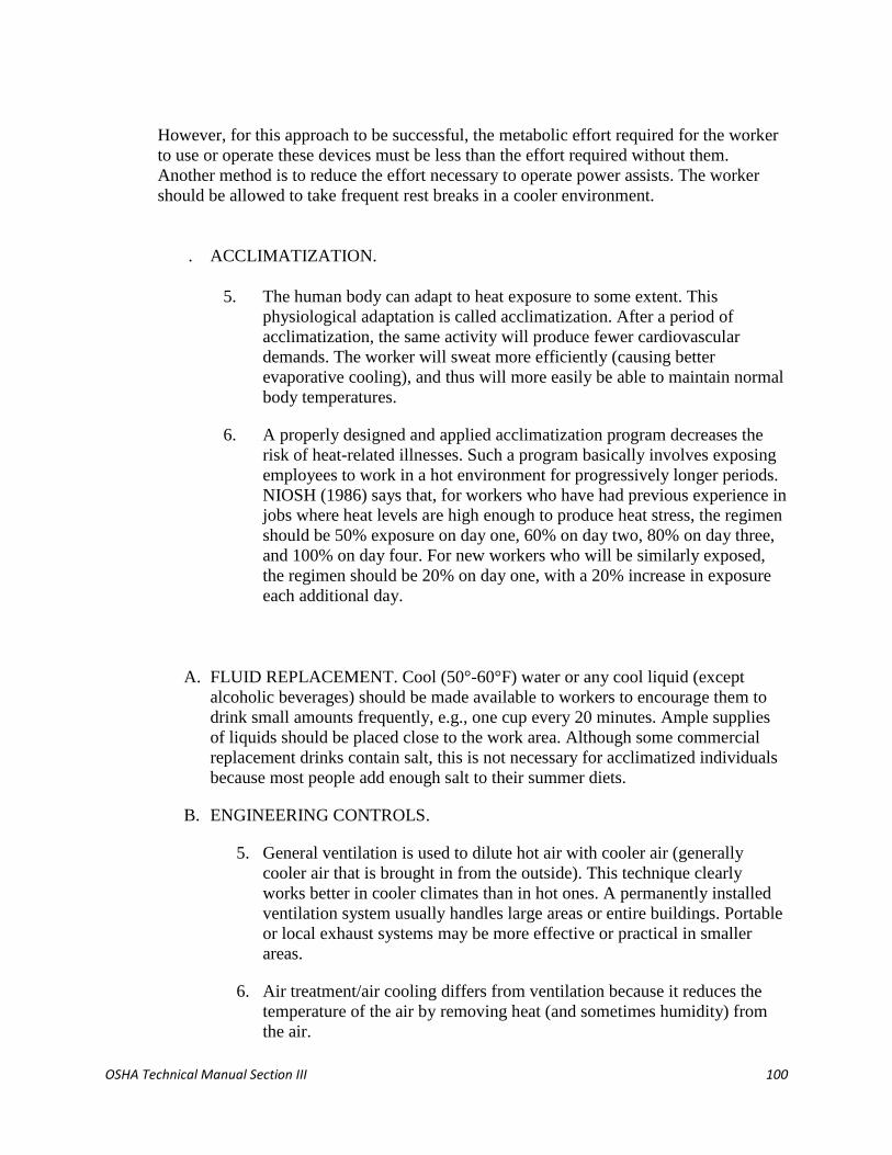
OSHA Technical Manual Section III 100
However, for this approach to be successful, the metabolic effort required for the worker
to use or operate these devices must be less than the effort required without them.
Another method is to reduce the effort necessary to operate power assists. The worker
should be allowed to take frequent rest breaks in a cooler environment.
. ACCLIMATIZATION.
5. The human body can adapt to heat exposure to some extent. This
physiological adaptation is called acclimatization. After a period of
acclimatization, the same activity will produce fewer cardiovascular
demands. The worker will sweat more efficiently (causing better
evaporative cooling), and thus will more easily be able to maintain normal
body temperatures.
6. A properly designed and applied acclimatization program decreases the
risk of heat-related illnesses. Such a program basically involves exposing
employees to work in a hot environment for progressively longer periods.
NIOSH (1986) says that, for workers who have had previous experience in
jobs where heat levels are high enough to produce heat stress, the regimen
should be 50% exposure on day one, 60% on day two, 80% on day three,
and 100% on day four. For new workers who will be similarly exposed,
the regimen should be 20% on day one, with a 20% increase in exposure
each additional day.
A. FLUID REPLACEMENT. Cool (50°-60°F) water or any cool liquid (except
alcoholic beverages) should be made available to workers to encourage them to
drink small amounts frequently, e.g., one cup every 20 minutes. Ample supplies
of liquids should be placed close to the work area. Although some commercial
replacement drinks contain salt, this is not necessary for acclimatized individuals
because most people add enough salt to their summer diets.
B. ENGINEERING CONTROLS.
5. General ventilation is used to dilute hot air with cooler air (generally
cooler air that is brought in from the outside). This technique clearly
works better in cooler climates than in hot ones. A permanently installed
ventilation system usually handles large areas or entire buildings. Portable
or local exhaust systems may be more effective or practical in smaller
areas.
6. Air treatment/air cooling differs from ventilation because it reduces the
temperature of the air by removing heat (and sometimes humidity) from
the air.

OSHA Technical Manual Section III 101
7. Air conditioning is a method of air cooling, but it is expensive to install
and operate. An alternative to air conditioning is the use of chillers to
circulate cool water through heat exchangers over which air from the
ventilation system is then passed; chillers are more efficient in cooler
climates or in dry climates where evaporative cooling can be used.
8. Local air cooling can be effective in reducing air temperature in specific
areas. Two methods have been used successfully in industrial settings.
One type, cool rooms, can be used to enclose a specific workplace or to
offer a recovery area near hot jobs. The second type is a portable blower
with built-in air chiller. The main advantage of a blower, aside from
portability, is minimal set-up time.
9. Another way to reduce heat stress is to increase the air flow or convection
using fans, etc. in the work area (as long as the air temperature is less than
the worker's skin temperature). Changes in air speed can help workers stay
cooler by increasing both the convective heat exchange (the exchange
between the skin surface and the surrounding air) and the rate of
evaporation. Because this method does not actually cool the air, any
increases in air speed must impact the worker directly to be effective.
If the dry bulb temperature is higher than 35°C (95°F), the hot air passing
over the skin can actually make the worker hotter. When the temperature
is more than 35°C and the air is dry, evaporative cooling may be improved
by air movement, although this improvement will be offset by the
convective heat. When the temperature exceeds 35°C and the relative
humidity is 100%, air movement will make the worker hotter. Increases in
air speed have no effect on the body temperature of workers wearing
vapor-barrier clothing.
10. Heat conduction methods include insulating the hot surface that generates
the heat and changing the surface itself.
11. Simple engineering controls, such as shields, can be used to reduce radiant
heat, i.e. heat coming from hot surfaces within the worker's line of sight.
Surfaces that exceed 35°C (95°F) are sources of infrared radiation that can
add to the worker's heat load. Flat black surfaces absorb heat more than
smooth, polished ones. Having cooler surfaces surrounding the worker
assists in cooling because the worker's body radiates heat toward them.
With some sources of radiation, such as heating pipes, it is possible to use
both insulation and surface modifications to achieve a substantial
reduction in radiant heat. Instead of reducing radiation from the source,
shielding can be used to interrupt the path between the source and the
worker. Polished surfaces make the best barriers, although special glass or
metal mesh surfaces can be used if visibility is a problem.

OSHA Technical Manual Section III 102
Shields should be located so that they do not interfere with air flow, unless
they are also being used to reduce convective heating. The reflective
surface of the shield should be kept clean to maintain its effectiveness.
C. ADMINISTRATIVE CONTROLS AND WORK PRACTICES.
0. Training is the key to good work practices. Unless all employees
understand the reasons for using new, or changing old, work practices, the
chances of such a program succeeding are greatly reduced.
1. NIOSH (1986) states that a good heat stress training program should
include at least the following components:
Knowledge of the hazards of heat stress;
Recognition of predisposing factors, danger signs, and symptoms;
Awareness of first-aid procedures for, and the potential health
effects of, heat stroke;
Employee responsibilities in avoiding heat stress;
Dangers of using drugs, including therapeutic ones, and alcohol in
hot work environments;
Use of protective clothing and equipment; and
Purpose and coverage of environmental and medical surveillance
programs and the advantages of worker participation in such
programs.
2. Hot jobs should be scheduled for the cooler part of the day, and routine
maintenance and repair work in hot areas should be scheduled for the
cooler seasons of the year.
D. WORKER MONITORING PROGRAMS.
0. Every worker who works in extraordinary conditions that increase the risk
of heat stress should be personally monitored. These conditions include
wearing semipermeable or impermeable clothing when the temperature
exceeds 21°C (69.8°F), working at extreme metabolic loads (greater than
500 kcal/hour), etc.
1. Personal monitoring can be done by checking the heart rate, recovery heart
rate, oral temperature, or extent of body water loss.
2. To check the heart rate, count the radial pulse for 30 seconds at the
beginning of the rest period. If the heart rate exceeds 110 beats per minute,
shorten the next work period by one third and maintain the same rest
period.
3. The recovery heart rate can be checked by comparing the pulse rate taken
at 30 seconds (P1) with the pulse rate taken at 2.5 minutes (P3) after the
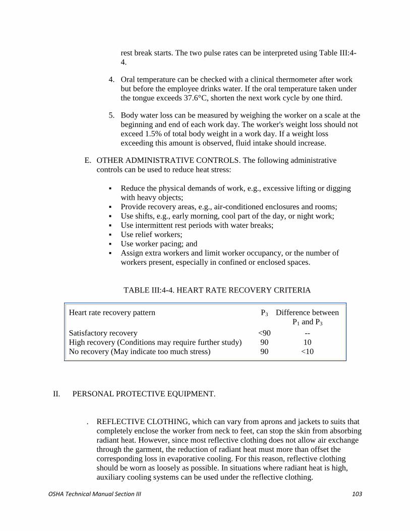
OSHA Technical Manual Section III 103
rest break starts. The two pulse rates can be interpreted using Table III:4-
4.
4. Oral temperature can be checked with a clinical thermometer after work
but before the employee drinks water. If the oral temperature taken under
the tongue exceeds 37.6°C, shorten the next work cycle by one third.
5. Body water loss can be measured by weighing the worker on a scale at the
beginning and end of each work day. The worker's weight loss should not
exceed 1.5% of total body weight in a work day. If a weight loss
exceeding this amount is observed, fluid intake should increase.
E. OTHER ADMINISTRATIVE CONTROLS. The following administrative
controls can be used to reduce heat stress:
Reduce the physical demands of work, e.g., excessive lifting or digging
with heavy objects;
Provide recovery areas, e.g., air-conditioned enclosures and rooms;
Use shifts, e.g., early morning, cool part of the day, or night work;
Use intermittent rest periods with water breaks;
Use relief workers;
Use worker pacing; and
Assign extra workers and limit worker occupancy, or the number of
workers present, especially in confined or enclosed spaces.
TABLE III:4-4. HEART RATE RECOVERY CRITERIA
Heart rate recovery pattern P3 Difference between
P1 and P3
Satisfactory recovery
High recovery (Conditions may require further study)
No recovery (May indicate too much stress)
<90
90
90
--
10
<10
II. PERSONAL PROTECTIVE EQUIPMENT.
. REFLECTIVE CLOTHING, which can vary from aprons and jackets to suits that
completely enclose the worker from neck to feet, can stop the skin from absorbing
radiant heat. However, since most reflective clothing does not allow air exchange
through the garment, the reduction of radiant heat must more than offset the
corresponding loss in evaporative cooling. For this reason, reflective clothing
should be worn as loosely as possible. In situations where radiant heat is high,
auxiliary cooling systems can be used under the reflective clothing.

OSHA Technical Manual Section III 104
A. AUXILIARY BODY COOLING.
0. Commercially available ice vests, though heavy, may accommodate as
many as 72 ice packets, which are usually filled with water. Carbon
dioxide (dry ice) can also be used as a coolant. The cooling offered by ice
packets lasts only 2 to 4 hours at moderate to heavy heat loads, and
frequent replacement is necessary. However, ice vests do not encumber
the worker and thus permit maximum mobility. Cooling with ice is also
relatively inexpensive.
1. Wetted clothing is another simple and inexpensive personal cooling
technique. It is effective when reflective or other impermeable protective
clothing is worn. The clothing may be wetted terry cloth coveralls or
wetted two-piece, whole-body cotton suits. This approach to auxiliary
cooling can be quite effective under conditions of high temperature and
low humidity, where evaporation from the wetted garment is not
restricted.
2. Water-cooled garments range from a hood, which cools only the head, to
vests and "long johns," which offer partial or complete body cooling. Use
of this equipment requires a battery-driven circulating pump, liquid-ice
coolant, and a container.
Although this system has the advantage of allowing wearer mobility, the
weight of the components limits the amount of ice that can be carried and
thus reduces the effective use time. The heat transfer rate in liquid cooling
systems may limit their use to low-activity jobs; even in such jobs, their
service time is only about 20 minutes per pound of cooling ice. To keep
outside heat from melting the ice, an outer insulating jacket should be an
integral part of these systems.
3. Circulating air is the most highly effective, as well as the most
complicated, personal cooling system. By directing compressed air around
the body from a supplied air system, both evaporative and convective
cooling are improved. The greatest advantage occurs when circulating air
is used with impermeable garments or double cotton overalls.
One type, used when respiratory protection is also necessary, forces
exhaust air from a supplied-air hood ("bubble hood") around the neck and
down inside an impermeable suit. The air then escapes through openings
in the suit. Air can also be supplied directly to the suit without using a
hood in three ways:
by a single inlet;
by a distribution tree; or
by a perforated vest.

OSHA Technical Manual Section III 105
In addition, a vortex tube can be used to reduce the temperature of
circulating air. The cooled air from this tube can be introduced either
under the clothing or into a bubble hood. The use of a vortex tube
separates the air stream into a hot and cold stream; these tubes also can be
used to supply heat in cold climates. Circulating air, however, is noisy and
requires a constant source of compressed air supplied through an attached
air hose.
One problem with this system is the limited mobility of workers whose
suits are attached to an air hose. Another is that of getting air to the work
area itself. These systems should therefore be used in work areas where
workers are not required to move around much or to climb. Another
concern with these systems is that they can lead to dehydration. The cool,
dry air feels comfortable and the worker may not realize that it is
important to drink liquids frequently.
B. RESPIRATOR USAGE. The weight of a self-contained breathing apparatus
(SCBA) increases stress on a worker, and this stress contributes to overall heat
stress. Chemical protective clothing such as totally encapsulating chemical
protection suits will also add to the heat stress problem.
III. BIBLIOGRAPHY.
American Conference of Governmental Industrial Hygienists (ACGIH). 1990. Documentation of
the Threshold Limit Values and Biological Exposure Indices. 6th ed. Cincinnati: American
Conference of Governmental Industrial Hygienists.
American Conference of Governmental Industrial Hygienists (ACGIH). 1992. 1992-1993
Threshold Limit Values for Chemical Substances and Physical Agents and Biological Exposure
Indices. Cincinnati: American Conference of Governmental Industrial Hygienists.
American Industrial Hygiene Association (AIHA). 1975. Heating and Cooling for Man in
Industry. 2nd ed. Akron, OH: American Industrial Hygiene Association.
Electric Power Research Institute (EPRI). 1987. Heat-Stress Management Program for Nuclear
Power Plants. Palo Alto, CA: Electric Power Research Institute.
Eastman Kodak Company. 1983. Ergonomic Design for People at Work. Vol. II. Belmont, CA:
Lifetime Learning Publications.
National Institute for Occupational Safety and Health. Criteria for a Recommended Standard--
Occupational Exposure to Hot Environments. DHHS (NIOSH) Publication No. 86-113, April
1986.

OSHA Technical Manual Section III 106
National Institute for Occupational Safety and Health. Occupational Safety and Health Guidance
Manual for Hazardous Waste Site Activities. DHHS (NIOSH) Publication No. 85-115, 1985.
National Institute for Occupational Safety and Health. Standards for Occupational Exposures to
Hot Environments: Proceedings of a Symposium. DHHS (NIOSH) Publication No. 76-100,
January 1976.
National Institute for Occupational Safety and Health. Working in Hot Environments. DHHS
(NIOSH) Publication No. 86-112. Revised 1986.
National Safety Council. 1985. Pocket Guide to Heat Stress. Chicago, IL: National Safety
Council.
Ramsey, J. D., Buford, C. L., Beshir, M.Y., and Jensen, R .C. Effects of Workplace Thermal
Conditions on Safe Work Behavior. Journal of Safety Research 14:105-114, 1983.
Zenz, C. 1988. Occupational Medicine: Principles and Practical Applications. 2nd ed. St. Louis,
MO: Mosby Year Book, Inc.
APPENDIX III:4-1. HEAT STRESS: GENERAL WORKPLACE REVIEW.
NOTE: Listed below are sample questions that the Compliance Officer may wish to consider
when investigating heat stress in the workplace.
WORKPLACE DESCRIPTION.
A. Type of business
B. Heat-producing equipment or processes used
C. Previous history (if any) of heat-related problems
D. At "hot" spots:
o Is the heat steady or intermittent?
o Number of employees exposed?
o For how many hours per day?
o Is potable water available?
o Are supervisors trained to detect/evaluate heat stress symptoms?
ARE EXPOSURES TYPICAL FOR A WORKPLACE IN THIS INDUSTRY?
A. Weather at Time of Review
B. Temperature
C. Humidity
D. Air velocity

OSHA Technical Manual Section III 107
E. Is Day Typical of Recent Weather Conditions?
(Get information from the Weather Bureau)
F. Heat-Reducing Engineering Controls
G. Ventilation in place?
H. Ventilation operating?
I. Air conditioning in place?
J. Air conditioning operating?
K. Fans in place?
L. Fans operating?
M. Shields or insulation between sources and employees?
N. Are reflective faces of shields clean?
WORK PRACTICES TO DETECT, EVALUATE, AND PREVENT OR REDUCE HEAT
STRESS.
A. Training program?
B. Content?
C. Where given?
D. For whom?
E. Liquid replacement program?
F. Acclimatization program?
G. Work/rest schedule?
H. Scheduling of work (during cooler parts of shift, cleaning and maintenance during shut-
downs, etc.)
I. Cool rest areas (including shelter at outdoor work sites)?
J. Heat monitoring program?
K. Personal Protective Equipment
L. Reflective clothing in use?
M. Ice and/or water-cooled garments in use?
N. Wetted undergarments (used with reflective or impermeable clothing) in use?
O. Circulating air systems in use?
P. First Aid Program
Q. Trained personnel?
R. Provision for rapid cool-down?
S. Procedures for getting medical attention?
T. Transportation to medical facilities readily available for heat stroke victims?
U. Medical Screening and Surveillance Program
V. Content?
W. Who manages program?
X. Additional Comments
(Use additional pages as needed.)
APPENDIX III: 4-2. HEAT STRESS-RELATED ILLNESS OR ACCIDENT FOLLOW-UP.

OSHA Technical Manual Section III 108
A. Describe events leading up to the episode.
B. Evaluation/comments by other workers at the scene.
C. Work at time of episode (heavy, medium, light)?
D. How long was affected employee working at site prior to episode?
E. Medical history of affected worker, if known.
F. Appropriate engineering controls in place?
G. Appropriate engineering controls in operation?
H. Appropriate work practices used by affected employee(s)?
I. Appropriate personal protective equipment available?
J. Appropriate personal protective equipment in use?
K. Medical screening for heat stress and continued surveillance for signs of heat stress given
other employees?
L. Additional comments regarding specific episode(s): (Use additional pages as needed.)
APPENDIX III: 4-3. MEASUREMENT OF WET BULB GLOBE TEMPERATURE.
Measurement is often required of those environmental factors that most nearly correlate with
deep body temperature and other physiological responses to heat. At the present time, the Wet
Bulb Globe Temperature Index (WBGT) is the most used technique to measure these
environmental factors. WBGT values are calculated by the following equations:
Equation III:4-4. Indoor or Outdoor Wet Bulb Globe Temperature Indexes (WBGI) Indoor or
outdoors with no solar load
WBGT = 0.7NWB + 0.3GT
Outdoors with solar load
WBGT = 0.7NWB + 0.2GT + 0.1DB
where: WBGT = Wet Bulb Globe Temperature Index
NWB = Natural Wet-Bulb Temperature
DB = Dry-Bulb (air) Temperature
GT = Globe Thermometer Temperature
The determination of WBGT requires the use of a black globe thermometer, a natural (static)
wet-bulb thermometer, and a dry-bulb thermometer. The measurement of environmental factors
shall be performed as follows:
1. The range of the dry and the natural wet-bulb thermometers should be -5°C to +50°C, with an
accuracy of ±0.5°C. The dry bulb thermometer must be shielded from the sun and the other
radiant surfaces of the environment without restricting the airflow around the bulb. The wick of
the natural wet bulb thermometer should be kept wet with distilled water for at least one-half

OSHA Technical Manual Section III 109
hour before the temperature reading is made. It is not enough to immerse the other end of the
wick into a reservoir of distilled water and wait until the whole wick becomes wet by capillarity.
The wick must be wetted by direct application of water from a syringe one-half hour before each
reading. The wick must cover the bulb of the thermometer and an equal length of additional wick
must cover the stem above the bulb. The wick should always be clean, and new wicks should be
washed before using.
2. A globe thermometer, consisting of a 15 cm (6-inch) in diameter hollow copper sphere painted
on the outside with a matte black finish, or equivalent, must be used. The bulb or sensor of a
thermometer (range -5°C to +100°C with an accuracy of ±0.5°C) must be fixed in the center of
the sphere. The globe thermometer should be exposed at least 25 minutes before it is read.
3. A stand should be used to suspend the three thermometers so that they do not restrict free air
flow around the bulbs and the wet-bulb and globe thermometer are not shaded.
4. It is permissible to use any other type of temperature sensor that gives a reading similar to that
of a mercury thermometer under the same conditions.
5. The thermometers must be placed so that the readings are representative of the employee's
work or rest areas, as appropriate.
Once the WBGT has been estimated, employers can estimate workers' metabolic heat load (see
Tables III:4-1 and III:4-2) and use the ACGIH method to determine the appropriate work/rest
regimen, clothing, and equipment to use to control the heat exposures of workers in their
facilities.

OSHA Technical Manual Section III 110
SECTION III: CHAPTER 6
LASER HAZARDS
Contents:
I. Introduction
II. Nonbeam Laser Hazards
III. Biological Effects of the Laser Beam
IV. Laser Hazard Classifications
V. Investigational Guidelines
VI. Control Measures and Safety Programs
VII. Bibliography
Appendix III:6-1. FDA-CDRH Requirements for Laser Products
Appendix III:6-2. FDA-CDRH Federal Laser Product Performance Standard Evaluation
Outline
Appendix III:6-3. The American National Standards Institute (ANSI)
Appendix III:6-4. Warning Signs
Appendix III:6-5. Glossary of Laser Terms
For problems with accessibility in using figures and illustrations in this document, please contact
the
Office of Science and Technology Assessment at (202) 693-2095.
I. INTRODUCTION.
The term LASER is an acronym for Light Amplification by Stimulated Emission of
Radiation. Light can be produced by atomic processes which generate laser light. A laser
consists of an optical cavity, a pumping system, and an appropriate lasing medium
(Figure III:6-1).
FIGURE III:6-1 COMPONENTS OF A LASER
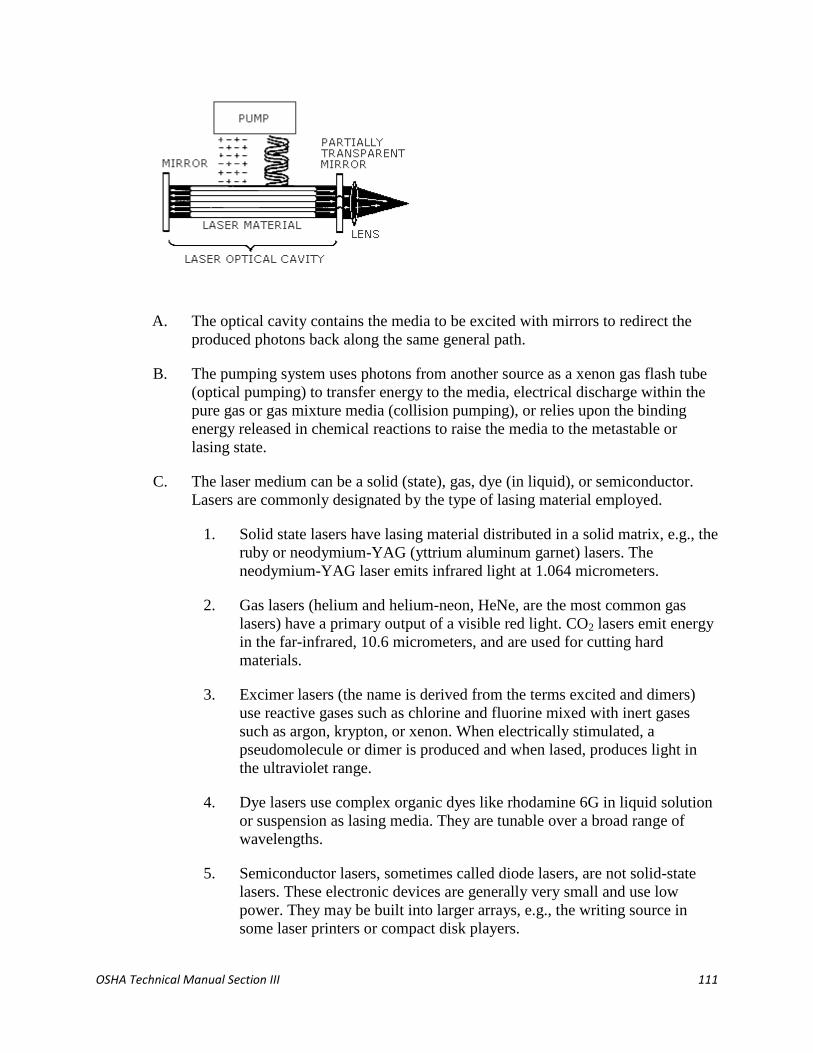
OSHA Technical Manual Section III 111
A. The optical cavity contains the media to be excited with mirrors to redirect the
produced photons back along the same general path.
B. The pumping system uses photons from another source as a xenon gas flash tube
(optical pumping) to transfer energy to the media, electrical discharge within the
pure gas or gas mixture media (collision pumping), or relies upon the binding
energy released in chemical reactions to raise the media to the metastable or
lasing state.
C. The laser medium can be a solid (state), gas, dye (in liquid), or semiconductor.
Lasers are commonly designated by the type of lasing material employed.
1. Solid state lasers have lasing material distributed in a solid matrix, e.g., the
ruby or neodymium-YAG (yttrium aluminum garnet) lasers. The
neodymium-YAG laser emits infrared light at 1.064 micrometers.
2. Gas lasers (helium and helium-neon, HeNe, are the most common gas
lasers) have a primary output of a visible red light. CO2 lasers emit energy
in the far-infrared, 10.6 micrometers, and are used for cutting hard
materials.
3. Excimer lasers (the name is derived from the terms excited and dimers)
use reactive gases such as chlorine and fluorine mixed with inert gases
such as argon, krypton, or xenon. When electrically stimulated, a
pseudomolecule or dimer is produced and when lased, produces light in
the ultraviolet range.
4. Dye lasers use complex organic dyes like rhodamine 6G in liquid solution
or suspension as lasing media. They are tunable over a broad range of
wavelengths.
5. Semiconductor lasers, sometimes called diode lasers, are not solid-state
lasers. These electronic devices are generally very small and use low
power. They may be built into larger arrays, e.g., the writing source in
some laser printers or compact disk players.

OSHA Technical Manual Section III 112
D. The wavelength output from a laser depends upon the medium being excited.
Table III:6-1 lists most of the laser types and their wavelength ouput defined by
the medium being excited. Laser use today is not restricted to the laboratory or
specialized industries. Table III:6-2 lists some of the major uses of lasers.
TABLE III:6-1. WAVELENGTHS OF MOST COMMON LASERS
Laser type
Wavelength
(µmeters)
Laser type
Wavelength
(µmeters)
Argon fluoride (Excimer-UV)
Krypton chloride (Excimer-UV)
Krypton fluoride (Excimer-UV)
Xenon chloride (Excimer-UV)
Xenon fluoride (Excimer-UV)
Helium cadmium (UV)
Nitrogen (UV)
Helium cadmium (violet)
Krypton (blue)
Argon (blue)
Copper vapor (green)
Argon (green)
Krypton (green)
Frequency doubled
Nd YAG (green)
Helium neon (green)
Krypton (yellow)
Copper vapor (yellow)
0.193
0.222
0.248
0.308
0.351
0.325
0.337
0.441
0.476
0.488
0.510
0.514
0.528
0.532
0.543
0.568
0.570
Helium neon (yellow)
Helium neon (orange)
Gold vapor (red)
Helium neon (red)
Krypton (red)
Rohodamine 6G dye (tunable)
Ruby (CrAlO3) (red)
Gallium arsenide (diode-NIR)
Nd:YAG (NIR)
Helium neon (NIR)
Erbium (NIR)
Helium neon (NIR)
Hydrogen fluoride (NIR)
Carbon dioxide (FIR)
Carbon dioxide (FIR)
0.594
0.610
0.627
0.633
0.647
0.570-0.650
0.694
0.840
1.064
1.15
1.504
3.39
2.70
9.6
10.6
Key: UV = ultraviolet (0.200-0.400 µm)
VIS = visible (0.400-0.700 µm)
NIR = near infrared (0.700-1.400 µm)
TABLE III:6-2. MAJOR CATEGORIES OF LASER USE
Alignment
Annealing
Balancing
Biomedical
Cellular research
Dental
Diagnostics
Dermatology
Ophthalmology
Drilling
Entertainment
Heat treating
Holography
Information handling
Copying
Displays
Plate making
Printing
Plasma diagnostics
Spectroscopy
Velocimetry
Lidar
Special photography
Scanning microscopy
Military
Distance ranging
Rifle simulation

OSHA Technical Manual Section III 113
Surgery
Communications
Construction
Alignment
Ranging
Surveying
Cutting
Displays
Reading
Scanning
Typesetting
Videodisk
Marking
Laboratory instruments
Interferometry
Metrology
Weaponry
Nondestructive training
Scanning
Sealing
Scribing
Soldering
Welding
II. NONBEAM LASER HAZARDS.
In some laser operations, particularly in the research laboratory, general safety and health
guidelines should be considered.
A. INDUSTRIAL HYGIENE. Potential hazards associated with compressed gases,
cryogenic materials, toxic and carcinogenic materials and noise should be
considered. Adequate ventilation shall be installed to reduce noxious or
potentially hazardous fumes and vapors, produced by laser welding, cutting and
other target interactions, to levels below the appropriate threshold limit values,
e.g., American Conference of Governmental Industrial Hygienists (ACGIH)
threshold limit values (TLV's) or Occupational Safety and Health
Administration's (OSHA) permissible exposure limits (PEL's).
B. EXPLOSION HAZARDS. High-pressure arc lamps and filament lamps or laser
welding equipment shall be enclosed in housings which can withstand the
maximum pressures resulting from lamp explosion or disintegration. The laser
target and elements of the optical train which may shatter during laser operation
shall also be enclosed.
C. NONBEAM OPTICAL RADIATION HAZARDS. This relates to optical beam
hazards other than laser beam hazards. Ultraviolet radiation emitted from laser
discharge tubes, pumping lamps and laser welding plasmas shall be suitably
shielded to reduce exposure to levels below the ANSI Z 136.1 (extended source),
OSHA PEL's, and/or ACGIH TLV's.
D. COLLATERAL RADIATION. Radiation, other than laser radiation, associated
with the operation of a laser or laser system, e.g., radio frequency (RF) energy
associated with some plasma tubes, x-ray emission associated with the high
voltage power supplies used with excimer lasers, shall be maintained below the
applicable protection guides. The appropriate protection guide for RF and
microwave energy is that given in the American National Standard "Safety levels
with respect to human exposure to radio frequency electromagnetic fields, 300
kHz to 100 GHz," ANSI C95.1; the appropriate protection guides for exposure to

OSHA Technical Manual Section III 114
X-ray emission is found in the Department of Labor Occupational Safety and
Health Standards, 29 CFR Part 1910.1096 and the applicable State Codes. Lasers
and laser systems which, by design, would be expected to generate appreciable
levels of collateral radiation, should be monitored.
E. ELECTRICAL HAZARDS. The intended application of the laser equipment
determines the method of electrical installation and connection to the power
supply circuit (for example, conduit versus flexible cord). All equipment shall be
installed in accordance with the National Electrical Code and the Occupational
Safety and Health Act. [Additional specific recommendations can be found in
Section 7.4 of ANSI Z 136.1 (1993)].
F. FLAMMABILITY OF LASER BEAM ENCLOSURES. Enclosure of Class IV
laser beams and terminations of some focused Class IIIB lasers, can result in
potential fire hazards if the enclosure materials are exposed to irradiances
exceeding 10 W/cm2. Plastic materials are not precluded as an enclosure material,
but their use and potential for flammability and toxic fume release following
direct exposure should be considered. Flame-resistant materials and commercially
available products specifically designed for laser enclosures should also be
considered.
III. BIOLOGICAL EFFECTS OF THE LASER BEAM.
A. EYE INJURY. Because of the high degree of beam collimation, a laser serves as
an almost ideal point source of intense light. A laser beam of sufficient power can
theoretically produce retinal intensities at magnitudes that are greater than
conventional light sources, and even larger than those produced when directly
viewing the sun. Permanent blindness can be the result.
B. THERMAL INJURY. The most common cause of laser-induced tissue damage is
thermal in nature, where the tissue proteins are denatured due to the temperature
rise following absorption of laser energy.
1. The thermal damage process (burns) is generally associated with lasers
operating at exposure times greater than 10 microseconds and in the
wavelength region from the near ultraviolet to the far infrared (0.315 µm-
103 µm). Tissue damage may also be caused by thermally induced
acoustic waves following exposures to sub-microsecond laser exposures.
2. With regard to repetitively pulsed or scanning lasers, the major
mechanism involved in laser-induced biological damage is a thermal
process wherein the effects of the pulses are additive. The principal
thermal effects of laser exposure depend upon the following factors:

OSHA Technical Manual Section III 115
The absorption and scattering coefficients of the tissues at the laser
wavelength. See Table III:6-1 for a summary of more common
laser types and wavelengths.
Irradiance or radiant exposure of the laser beam.
Duration of the exposure and pulse repetition characteristics,
where applicable.
Extent of the local vascular flow.
Size of the area irradiated.
C. OTHER.
1. Other damage mechanisms have also been demonstrated for other specific
wavelength ranges and/or exposure times. For example, photochemical
reactions are the principal cause of threshold level tissue damage
following exposures to either actinic ultraviolet radiation (0.200 µm-0.315
µm) for any exposure time or "blue light" visible radiation (0.400 µm-
0.550 µm) when exposures are greater than 10 seconds.
2. To the skin, UV-A (0.315 µm-0.400 µm) can cause hyperpigmentation
and erythema.
3. Exposure in the UV-B range is most injurious to skin. In addition to
thermal injury caused by ultraviolet energy, there is the possibility of
radiation carcinogenesis from UV-B (0.280 mm - 0.315 mm) either
directly on DNA or from effects on potential carcinogenic intracellular
viruses.
4. Exposure in the shorter UV-C (0.200 µm-0.280 µm) and the longer UV-A
ranges seems less harmful to human skin. The shorter wavelengths are
absorbed in the outer dead layers of the epidermis (stratum corneum) and
the longer wavelengths have an initial pigment-darkening effect followed
by erythema if there is exposure to excessive levels. These biological
effects are summarized in Table III:6-3.
5. The hazards associated with skin exposure are of less importance than eye
hazards; however, with the expanding use of higher-power laser systems,
particularly ultraviolet lasers, the unprotected skin of personnel may be
exposed to extremely hazardous levels of the beam power if used in an
unenclosed system design.
NOTE: The primary purpose of an exiting laser beam, e.g. cutting or
welding of hard materials, must not be forgotten! Some laser beams
designed for material alteration may be effective some distance from their
intended impact point.

OSHA Technical Manual Section III 116
TABLE III:6-3. SUMMARY OF BASIC BIOLOGICAL EFFECTS OF LIGHT
Photobiological spectral domain
Eye effects
Skin effects
Ultraviolet C (0.200-0.280 µm) Photokeratitis Erythema (sunburn)
Skin cancer
Ultraviolet B (0.280-315 µm) Photokeratitis Accelerated skin
aging
Increased
pigmentation
Ultraviolet A (0.315-0.400 µm) Photochemical UV
cataract
Pigment darkening
Skin burn
Visible (0.400-0.780 µm) Photochemical and
thermal retinal
injury
Photosensitive
reactions
Skin burn
Infrared A (0.780-1.400 µm) Cataract, retinal
burns
Skin burn
Infrared B (1.400-3.00 µm) Corneal burn
Aqueous flare
IR cataract
Skin burn
Infrared C (3.00-1000 µm) Corneal burn only Skin burn
IV. LASER HAZARD CLASSIFICATIONS.
A. INTRODUCTION.
1. The intent of laser hazard classification is to provide warning to users by
identifying the hazards associated with the corresponding levels of
accessible laser radiation through the use of labels and instruction. It also
serves as a basis for defining control measures and medical surveillance.
2. Lasers and laser systems received from manufacturers are required by
federal law, 21 CFR Part 1000, to be classified and appropriately labeled
by the manufacturer. It should be stressed, however, that the classification
may change whenever the laser or laser system is modified to accomplish
a given task.
3. It should also be stressed that an agency such as the Food and Drug
Administration's Center for Devices and Radiological Health
(FDA/CDRH) does not "approve" laser systems for medical use. The
manufacturer of the laser system first classifies the laser and then certifies

OSHA Technical Manual Section III 117
that it meets all performance requirements of the Federal Laser Product
Performance Standard (FLPPS). The forms submitted by the manufacturer
to FDA/CDRH are reviewed for technical accuracy, omissions, and errors.
If none are found, the manufacturer is notified only that the submission
appears to be complete. Therefore, all lasers and laser systems that are
manufactured by a company, or purchased by a company and relabeled
and placed into commerce, or incorporated into a system and placed into
commerce, shall be classified.
B. LASER HAZARD CLASSES.
1. Virtually all of the U.S. domestic as well as all international standards
divide lasers into four major hazard categories called the laser hazard
classifications. The classes are based upon a scheme of graded risk. They
are based upon the ability of a beam to cause biological damage to the eye
or skin. In the FLPPS, the classes are established relative to the Accessible
Emission Limits (AEL) provided in tables in the standard. In the ANSI Z
136.1 standard, the AEL is defined as the product of the Maximum
Permissible Exposure (MPE) level and the area of the limiting aperture.
For visible and near infrared lasers, the limiting aperture is based upon the
"worst-case" pupil opening and is a 7 mm circular opening.
2. Lasers and laser systems are assigned one of four broad Classes (I to IV)
depending on the potential for causing biological damage. The biological
basis of the hazard classes are summarized in Table III:6-4.
a. Class I: cannot emit laser radiation at known hazard levels
(typically continuous wave: cw 0.4 µW at visible wavelengths).
Users of Class I laser products are generally exempt from radiation
hazard controls during operation and maintenance (but not
necessarily during service).
Since lasers are not classified on beam access during service, most
Class I industrial lasers will consist of a higher class (high power)
laser enclosed in a properly interlocked and labeled protective
enclosure. In some cases, the enclosure may be a room (walk-in
protective housing) which requires a means to prevent operation
when operators are inside the room.
b. Class I.A.: a special designation that is based upon a 1000-second
exposure and applies only to lasers that are "not intended for
viewing" such as a supermarket laser scanner. The upper power
limit of Class I.A. is 4.0 mW. The emission from a Class I.A. laser
is defined such that the emission does not exceed the Class I limit
for an emission duration of 1000 seconds.
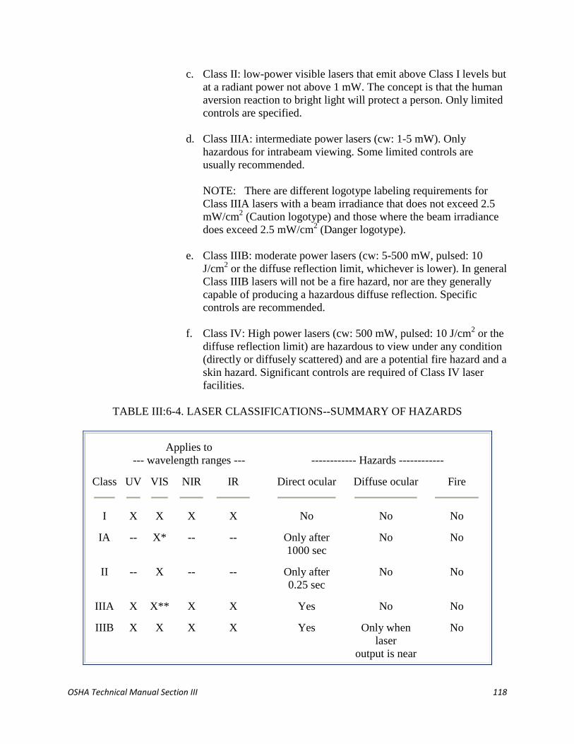
OSHA Technical Manual Section III 118
c. Class II: low-power visible lasers that emit above Class I levels but
at a radiant power not above 1 mW. The concept is that the human
aversion reaction to bright light will protect a person. Only limited
controls are specified.
d. Class IIIA: intermediate power lasers (cw: 1-5 mW). Only
hazardous for intrabeam viewing. Some limited controls are
usually recommended.
NOTE: There are different logotype labeling requirements for
Class IIIA lasers with a beam irradiance that does not exceed 2.5
mW/cm2 (Caution logotype) and those where the beam irradiance
does exceed 2.5 mW/cm2 (Danger logotype).
e. Class IIIB: moderate power lasers (cw: 5-500 mW, pulsed: 10
J/cm2 or the diffuse reflection limit, whichever is lower). In general
Class IIIB lasers will not be a fire hazard, nor are they generally
capable of producing a hazardous diffuse reflection. Specific
controls are recommended.
f. Class IV: High power lasers (cw: 500 mW, pulsed: 10 J/cm2 or the
diffuse reflection limit) are hazardous to view under any condition
(directly or diffusely scattered) and are a potential fire hazard and a
skin hazard. Significant controls are required of Class IV laser
facilities.
TABLE III:6-4. LASER CLASSIFICATIONS--SUMMARY OF HAZARDS
Applies to
--- wavelength ranges --- ------------ Hazards ------------
Class
UV
VIS
NIR
IR
Direct ocular
Diffuse ocular
Fire
I X X X X No No No
IA -- X* -- -- Only after
1000 sec
No No
II -- X -- -- Only after
0.25 sec
No No
IIIA X X** X X Yes No No
IIIB X X X X Yes Only when
laser
output is near
No

OSHA Technical Manual Section III 119
Class IIIB limit
of 0.5 Watt
IV X X X X Yes Yes Yes
Key: X
*
**
=
=
=
Indicates class applies in wavelength range.
Class IA applicable to lasers "not intended for viewing" ONLY.
CDRH Standard assigns Class IIIA to visible wavelengths ONLY.
ANSI Z 136.1 assigns Class IIIA to all wavelength ranges.
C. HOW TO DETERMINE THE CLASS OF LASERS DURING INSPECTION.
1. The classification of a laser or laser product is, in some instances, a rather
detailed process. It can involve determination of the AEL, measurement of
the laser emission, measurement/determination of the emission pulse
characteristics (if applicable), evaluation of various performance
requirements (protective housing, interlocks, etc.) as specified by the
FLPPS and/or ANSI standards.
2. It should be stressed that classification is a required specification provided
by the laser manufacturer and the label that specifies the class is found in
only one location on the laser product. The class of the laser will be
specified only on the lower left-hand corner (position three) of the
warning logotype label.
The logotype is the rectangular label that has the laser "sunburst" symbol
and the warning statement of CAUTION (Class II and some Class IIIA) or
DANGER (some Class IIIA, all Class IIIB and Class IV). This label will
also have the type of laser designated (HeNe, Argon, CO2, etc.) and the
power or energy output specified (1 mW CW/MAX, 100 mJ pulsed, etc.).
3. Class I lasers have no required labeling indicating the Class I status.
Although the FLPPS requires no classification labeling of Class I lasers it
does require detailed compliance with numerous other performance
requirements (i.e., protective housing, identification and compliance
labeling, interlocking, etc.)
D. ANSI Z 136.2 OPTICAL FIBER SERVICE GROUP DESIGNATIONS.
1. Optical Fiber Communication Systems (OFCS) and the associated optical
test sets use semiconductor lasers or LED transmitters that emit energy at
OSHA Technical Manual Section III 120
wavelengths typically in the range from 0.650 to 1.20 mm into the light-
guide fiber-optic cables.
2. All OFCS are designed to operate with the beam totally enclosed within
the fiber-optic and associated equipment and, therefore, are always
considered as Class I in normal operation.
3. The only risk for exposure would occur during installation and service
when light-guide cables are disconnected or during an infrequent
accidental cable break.
4. Under the requirements of the ANSI Z 136.2 (1988) Standard "For the
Safe Use of Optical Fiber Communication Systems Utilizing Laser Diode
and LED Sources," Optical Fiber Communication Systems (OFCS) are
assigned into one of four service group (SG) designations: SG1, SG2,
SG3a, SG3b, depending on the potential for an accessible beam to cause
biological damage.
5. The service group designations relate to the potential for ocular hazards to
occur only during accessible beam conditions. This would normally occur
only during periods of service to a OFCS. Such designations apply only
during periods of service in one of the following four service groups:
a. Service Group 1: An OFCS that is SG1 has a total output power
that is less than the Accessible Emission Limit (AEL) for Class I
and there is no risk of exceeding the Maximum Permissible
Irradiance (MPI) when viewing the end of a fiber with a
microscope, an eye-loupe or with the unaided eye.
b. Service Group 2: An OFCS is SG2 only if wavelengths between
0.400 and 0.700 mm are emitted and is potentially hazardous if
viewed for more than 0.25 second. (Note: At present there are
virtually no OFCS's that operate in this wavelength range.)
c. Service Group 3A: A SG 3A OFCS is not hazardous when viewed
with the unaided eye and is hazardous only when viewed with a
microscope or an eye-loupe.
d. Service Group 3B: OFCS that meet none of the above criteria are
designated as SG 3B.
NOTE: OFCS's where the total power is at or above 0.5W do not
meet the criteria for optical fiber service group designation. In this
case, the OFCS's are treated as a standard laser system.

OSHA Technical Manual Section III 121
V. INVESTIGATIONAL GUIDELINES.
A. REQUIREMENTS OF LASER STANDARDS. In the United States, several
organizations concern themselves with laser safety. These organizations include
the American National Standards Institute (ANSI); the Center for Devices and
Radiological Health (CDRH) of the Food and Drug Administration (FDA); the
Department of Labor's Occupational Safety and Health Administration (OSHA);
and the Council of Radiation Control Program Directors (CRCPD). Several state
governments and the CRCPD have developed a model state standard for laser
safety.
1. OSHA Regulatory Practice. At the present time, OSHA does not have a
comprehensive laser standard, though 29 CFR 1926.54 is applicable to the
construction industry. A standard for personal protective equipment
(Subpart I) may apply in some cases.
The construction standard 29 CFR 1926.102(b)(2), for eye and face
protection, states that "employees whose occupation or assignment
requires exposure to laser beams shall be furnished suitable laser safety
goggles which will protect for the specific wavelength of the laser and be
of optical density (O.D.) adequate for the energy involved."
OSHA citations are issued by invoking the general duty clause or, in some
cases, Subpart I. In such cases, the employers are required to revise their
reportedly unsafe work place using the recommendations and
requirements of such industry consensus standards as the ANSI Z 136.1
Standard. See also Table III:6-8.
2. Specific and Model State Laser Regulations. A few states currently have
laser regulations. Requirements are generally concerned with the
registration of lasers and the licensing of operators and institutions.
Physician-used and other medical lasers are generally exempt from state
requirements.
The complexity of state laser regulations may change in the future pending
adoption of the "Suggested State Regulation for Lasers" promulgated
through the Conference of Radiation Control Program Directors. This
model state standard has been adopted in part, for example, by Arizona
and Florida. Several other states have enacted some form of regulation.
Table III:6-5 summarizes state regulations.
TABLE III:6-5. SUMMARY OF CURRENT STATE LASER REGULATIONS
State Department Regulation

OSHA Technical Manual Section III 122
Alaska
Arizona*
Arkansas
Florida*
Georgia
Illinois
Massachusetts
Montana
New York
Pennsylvania
Texas
Washington
Environmental Conservation
Radiation Regulatory Agency
Division of Radiation Control
& Emergency Management
Department of Health &
Rehabilitative Services
Department of Public Health
Department of Nuclear Safety
Department of Public Health
Health & Environmental Services
Department of Labor
Environmental Resources
Department of Health
Labor & Industry
Title 18, Article 7
Act 460
Non-Ionizing Chapter: 10D-89
Chapter: 290-5-27
Chapter: 111 ½
105 CMR 21
92-003
Code Rule 50
Chapter: 203, Title 25
Radiation Control Act Parts 50, 60, 70
Chapter 296-62-WAC
* Using CRCPD "Model State" laser standard as basis.
3. FDA Center for Devices and Radiological Health Performance
Requirements.
a. The CDRH of the Department of Health and Human Services was
chartered by Congress to standardize the manufacture of lasers in
interstate commerce after August 2, 1976. CDRH also has the
responsibility for enforcing compliance with the medical devices
legislation. All manufacturers of surgical lasers must obtain
premarket approval of their devices through the CDRH.
b. FDA sanctions the exploratory use of lasers for specific procedures
through a process known as an Investigational Device Exemption
(IDE). Approval of an IDE permits the limited use of a laser
expressly for the purpose of conducting an investigation of the
laser's safety and effectiveness. Once an IDE has been prepared
and approved by the CDRH, the manufacturer may then actively
market the laser for that specific medical or surgical procedure.
c. The FDA/CDRH Federal Laser Product Performance Standard
(FLPPS) regulates the manufacturer of commercial laser products,
not the user. The standard does not contain specific design
specifications, but is a conceptual, performance standard which the

OSHA Technical Manual Section III 123
designer of laser products must consider. The intent is to insure
laser product safety.
d. FLPSS is applicable to lasers or laser systems sold by a company
within or imported into the U.S. In some cases it can also apply
when a laser or laser system is transferred within a company for
internal use within the U.S. The compliance procedure requires
implementation of the procedures and requirements as set forth in
the U.S. Federal Laser Product Performance Standard: 21 CFR
Part 1000 [parts 1040.10 and 1040.11].
e. Under the requirements of the FLPPS, the manufacturer is first
required to classify the laser as either a Class-I, Class-II, Class-
I.A., Class-IIIA, Class-IIIB, or Class-IV laser product and then to
certify (by means of a label on the product) as well as submit a
report demonstrating that all requirements (performance features)
of the compliance standard are met. Specific performance features
include:
protective housing;
protective housing warning labels and logotype labels;
product identification label and certification statement;
safety interlocks;
emission indicator;
remote interlock connector;
key control;
beam attenuator;
specification of control locations;
viewing optic limitations;
scanning beam safeguards; and
manual reset of beam cutoff.
f. FDA/CDRH performance requirements are tabulated in Appendix
III:6-1. An outline to assist in evaluating FLPPS laser system
performance requirements is included in Appendix III:6-2.
4. The American National Standard Institute (ANSI). An American National
Standard implies a consensus of those substantially concerned with its
scope and provisions. These standards are intended as a guide for
manufacturers, consumers, and the general public. However, there is no
inherent requirement for any person or company to adhere to an ANSI
standard. Compliance is voluntary unless specifically required by an
organization. For example, the U.S. Department of Energy requires
adherence to the ANSI Z 136.1 by their staff as well as by all contractor
organizations. Appendix III:6-3 summarizes ANSI Standards applicable to
laser safety.

OSHA Technical Manual Section III 124
B. LASER EXPOSURE LIMITS. At present either the FDA criteria for medical
lasers or the following ANSI standards can be useful in evaluating laser safety.
1. FDA Long-Term Exposure Limits. The FDA/CDRH Federal Laser
Product Performance Standard (FLPPS) assumes a linearly additive
biological effect for exposures to visible light between 10 and 10^4
seconds (2.8 hours). The standard accepts that a cumulative radiant energy
exposure of 3.85 millijoules (mJ) will not cause a biological effect. Hence
a 10-second total accumulated exposure corresponds to an average power
entering a 7-mm aperture of 385 microwatts (µW). For an exposure of
10^4 seconds, the average power would be 0.385 µW. In the FLPPS, the
power level of 0.385 µW is referred to as the Class I Accessible Emission
Limit (AEL) for a visible CW laser.
2. ANSI Z 136.1, Long-Term Exposure Limits.
a. The ANSI Z 136.1 (1993) standard is a "user" standard and therefore
provides maximum permissible exposure (MPE) limits. These were
derived by normalizing the power (or pulse energy) data derived from
biological research studies relative to a defined limiting aperture. For
example, in the visible and near-infrared spectra, the limiting aperture is
based upon the diameter of a fully dilated pupil of the human eye, 7 mm.
The area of a 7-mm pupil is 0.385 cm2. Hence, the irradiance limit for
long-term ocular exposure is computed by dividing the AEL value of
0.385 µW by the area of the limiting aperture of 0.385 cm2. This yields the
worst-case MPE value of 1.0 µW/cm2 for long-term exposure in the
wavelength range of 0.400 to 0.550 mm.
b. The ANSI Z 136 and FDA/CDRH allowable-exposure limits for
CW lasers (Class I limits) are essentially identical for wavelengths
between 0.400 and 0.550 µm. The ANSI limits are, however, more
relaxed for wavelengths between 0.550 and 1.40 µm. ANSI
recognizes a decreased biological hazard in the red and infrared
regions that is not recognized by the CDRH.
c. The ANSI Z 136 MPE level for a very long term exposure by a
helium-neon laser is, in fact, seventeen times greater than the
CDRH standard. In the 1976 revision, ANSI Z 136 introduced the
correction factor CB which has a value of 17.5 at the 0.633-µm
HeNe laser wavelength, and, thus, permitted a radiant exposure of
185 mJ/cm2 accumulated exposure for times from T1 = 453
seconds to 104 seconds, and about 18 w/cm2 (7 w in a 7-mm
limiting aperture) for continuous operation of exposure durations
exceeding 104 seconds.
3. ANSI Z 136.1, Repetitively Pulsed Exposures.

OSHA Technical Manual Section III 125
. The ANSI Z 136 standard requires a decrease in the maximum
permissible exposure (MPE) for scanned or repetitive-pulse
radiation as compared to continuous-wave radiation for pulse
repetition frequencies (PRF) in the general range of 1000-15000
Hz. Because of pulse additivity, scanned or repetitively pulsed
radiation with repetition rates less than 15 KHz have lower retinal
damage threshold levels than CW radiation of comparable power.
a. The ANSI Z 136 Standard includes a reduction factor of the
threshold for each of the single pulses based on biological data that
are not yet well explained by any theory. The FDA/CDRH
standard does not recognize this repetitive-pulse correction factor.
However, some experts envision the possibility of a repetitively
pulsed laser which is Class I by the FDA/CDRH standard could be
rated Class II or even Class IIIB by the ANSI Z 136 standard.
b. The ANSI standard requires that multiple-pulse (scanning) lasers
operating from 1 to 15,000 Hz have a correction to the single pulse
MPE. The correction factor is determined by taking the fourth root
of the total number of pulses (N) in a pulse train. Then, the
correction factor is calculated such that the MPE radiant exposure
or integrated radiance of an individual pulse within the train is
reduced by a factor N-¼
.
4. ANSI Z 136.1, Maximum Permissible Exposure Limits.
. a. A summary of Maximum Permissible Exposure (MPE) limits for
direct ocular exposures for some of the more common lasers is
presented in Table III:6-6. For further information on MPE values,
refer to the ANSI Z 136.1 "Safe Use of Lasers" Standard.
a. The information in Table III:6-6 provides the MPE value for
different lasers operating for different overall exposure times. The
times chosen were:
0.25 second: The human aversion time for bright-light
stimuli (the blink reflex). Thus, this becomes the "first line
of defense" for unexpected exposure to some lasers and is
the basis of the Class II concept.
10 seconds: The time period chosen by the ANSI Z 136.1
committees represents the optimum "worst-case" time
period for ocular exposures to infrared (principally near-
infrared) laser sources. It was argued that natural eye
motions dominate for periods longer than 10 seconds.
600 seconds: The time period chosen by the ANSI Z 136.1
committees represents a typical worst-case period for
viewing visible diffuse reflections during tasks such as
alignment.

OSHA Technical Manual Section III 126
30,000 seconds: The time period that represents a full 1-day
(8-hour) occupational exposure. This results from
computing the number of seconds in 8 hours; e.g.: 8 hours
× 60 minutes/hour × 60 seconds/minute = 28,800 seconds.
Rounded off, it becomes 30,000 seconds.
b. The "safety" exposure limits (MPE's) in Table III:6-6 are
expressed in irradiance terms (W/cm2) that would be measured at
the cornea. Note that they vary by wavelength and exposure time.
TABLE III:6-6. SUMMARY: MAXIMUM PERMISSIBLE EXPOSURE LIMITS*
Wave-
length -------------- MPE level (W/cm2) --------------
Laser type
(µm)
0.25 sec
10 sec
600 sec
30,000 sec
CO2 (CW) 10.6 --- 100.0 × 10⁻³
--- 100.0 × 10⁻³
Nd: YAG
(CW)
1.33 --- 5.1 × 10⁻³
--- 1.6 × 10⁻³
Nd: YAG
(CW)
1.064 --- 5.1 × 10⁻³
--- 1.6 × 10⁻³
Nd: YAG
(Q-switched) 1.064 --- 17.0 × 10⁻⁶
--- 2.3 × 10⁻⁶
GaAs
(Diode/CW) 0.840 --- 1.9 × 10⁻³
--- 610.0 × 10⁻⁶
HeNe (CW) 0.633 2.5 × 10⁻³
--- 293.0 × 10-
6
17.6 × 10⁻⁶
Krypton
(CW)
0.647
0.568
0.530
2.5 × 10⁻³
31.0 × 10⁻⁶
16.7 × 10⁻⁶
---
---
---
364.0 × 10-
6
2.5 × 10⁻³
2.5 × 10⁻³
28.5 × 10⁻⁶
18.6 × 10⁻⁶
1.0 × 10⁻⁶
Argon (CW) 0.514 2.5 × 10⁻³
--- 16.7 × 10⁻⁶
1.0 × 10⁻⁶
XeFl
(Excimer/
CW) 0.351 --- --- --- 33.3 × 10⁻⁶
XeCl
(Excimer/
CW) 0.308 --- --- --- 1.3 × 10⁻⁶
* Source: ANSI Z 136.1 (1993)
OSHA Technical Manual Section III 127
C. LASER HAZARD COMPUTATIONS.
1. NHZ Definition, Use, and Values.
a. The Nominal Hazard Zone (NHZ) describes the space within which the
level of direct, reflected, or scattered radiation during normal operation
exceeds the MPE. The NHZ associated with open-beam Class IIIB and
Class IV laser installations can be useful in assessing area hazards and
implementing controls.
b. It is often necessary in some applications where open beams are
required (e.g., industrial processing, laser robotics, surgical uses) to define
the area where the possibility exists for potentially hazardous exposure.
This is done by determining the NHZ. Consequently, persons outside the
NHZ boundary would be exposed below the MPE level and are considered
to be in a non-hazardous location.
c. The NHZ boundary may be defined, for example, by direct beams
(intrabeam) and diffusely scattered laser beams, as well as beams
transmitted from fiber optics and/or through lens arrays. The NHZ
perimeter is the envelope of MPE exposure levels from any specific laser
installation geometry.
d. The purpose of an NHZ evaluation is to define that space where control
measures are required. This is an important factor since, as the scope of
laser uses has expanded, controlling lasers by total enclosure in a
protective housing or interlocked room is limiting and, in many instances,
an expensive overreaction to the real hazards. The following factors are
required in NHZ computations:
laser power or energy output;
beam diameter;
beam divergence;
pulse repetition frequency (prf) (if applicable);
wavelength;
beam optics and beam path; and
maximum anticipated exposure duration.
e. Note that the ANSI Z 136 MPE value is required in all NHZ
calculations. Examples of NHZ calculations can be found in the appendix
of ANSI Z 136.1 (1993). In addition, computer software is also available
to assist in the computations for NHZ, optical densities of protective eye
wear, and other aspects of laser hazard analysis.

OSHA Technical Manual Section III 128
2. NHZ Example Summary. The intrabeam (direct) hazard for a Nd:YAG
laser extends from 792 meters to 1410 meters, depending upon whether a
10-second or 8-hour criterion is used, as summarized in Table III:6-7.
Similarly, with a lens on the laser, the hazard for a Nd:YAG laser exists
over a range from 6.3 meters to 11.3 meters. The diffuse reflection zone
for this laser type is, however, markedly smaller, 0.8 meter to 1.4 meters.
Nonetheless, the analysis suggests that operating personnel and support
staff close to the laser still need eye protection even for diffuse reflections.
Other calculations are also presented in Table III:6-7 for a 500-Watt CO2
and a 5-Watt argon laser. Note that the NHZ's do not vary for the CO2
laser (because the MPE values are nearly identical for 10-second and 8-
hour criteria). Also note that the diffuse reflection NHZ's are very small
except for the 8-hour criterion for the argon laser. In most cases, 0.25
second can be used with visible lasers unless intentional staring is required
or intended.
TABLE III:6-7. NHZ DISTANCE VALUES FOR VARIOUS LASERS
Exposure
----- Hazard range (meters) -----
Laser type
criteria
Diffuse
Lens-on-laser
Direct
Nd:YAG
100 Watt
1.064 µm
8 hours
10 seconds
1.4
0.8
11.3
6.3
1410
792
CO2
500 Watt
10.6 µm
8 hours
10 seconds
0.4
0.4
5.3
5.3
309
390
Argon
5.0 Watt
0.488 µm
8 hours
0.25 seconds
12.6
0.25
1.7 × 10³
33.3
25.2 ×
103
240
Laser criteria used for NHZ distance calculations:
Laser parameter
Nd-YAG
CO2
Argon
Wavelength (µm)
Beam power (Watts)
Beam divergence (mrad)
Beam size at aperture (mm)
Beam size at lens (mm)
1.064
100.0
2.0
2.0
6.3
10.6
500.0
2.0
20.0
30.0
0.488
5.0
1.0
2.0
3.0

OSHA Technical Manual Section III 129
Lens focal length (mm)
MPE for 8 hours (w/cm2)
MPE for 10 seconds (w/cm2) 5.1×10
3
MPE for 0.25 second (w/cm2)
25.4
1.6 × 10³
1.0 × 10⁵
---
200.0
1.0 × 10⁵
---
---
200.0
1.0
2.5 ×
103
Source: ANSI A 136.1 (1993)
1. INTRABEAM OPTICAL DENSITY DETERMINATION.
1. Based upon these typical exposure conditions, the optical density required
for suitable filtration can be determined. Optical density (OD) is a
logarithmic function defined by:
EQUATION III: 6-1. OPTICAL DENSITY
OD = log10 H 0
MPE
where:
H0
MPE
=
=
Anticipated worst-case exposure (J/cm2 or W/cm
2)
Maximum permissible exposure level expressed in the
same units as H0
2. Based upon the worst case exposure conditions outlined above, one can
determine the optical density recommended to provide adequate eye
protection for this laser. For example, the minimum optical density at the
0.514 µm argon laser wavelength for a 600-second direct intrabeam
exposure to the 5-watt maximum laser output can be determined as
follows:
Where:
f = 5 Watts
MPE = 16.7 W/cm2 (using 600-second criterion)
d = 7 mm (worst-case pupil size)
Computing the worst-case exposure H0:
H0 = [Power/Area] = f/A = 4f/ pd2
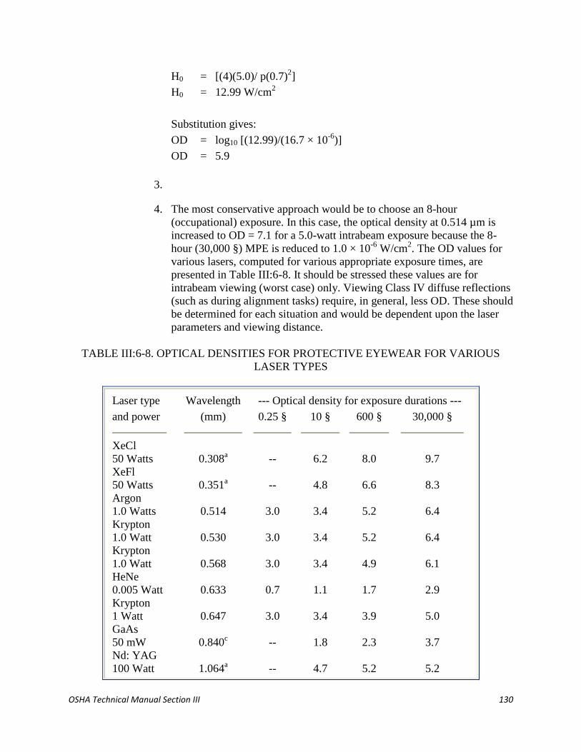
OSHA Technical Manual Section III 130
H0 = [(4)(5.0)/ p(0.7)2]
H0 = 12.99 W/cm2
Substitution gives:
OD = log10 [(12.99)/(16.7 × 10-6
)]
OD = 5.9
3.
4. The most conservative approach would be to choose an 8-hour
(occupational) exposure. In this case, the optical density at 0.514 µm is
increased to OD = 7.1 for a 5.0-watt intrabeam exposure because the 8-
hour (30,000 §) MPE is reduced to 1.0 × 10⁻⁶
W/cm2. The OD values for
various lasers, computed for various appropriate exposure times, are
presented in Table III:6-8. It should be stressed these values are for
intrabeam viewing (worst case) only. Viewing Class IV diffuse reflections
(such as during alignment tasks) require, in general, less OD. These should
be determined for each situation and would be dependent upon the laser
parameters and viewing distance.
TABLE III:6-8. OPTICAL DENSITIES FOR PROTECTIVE EYEWEAR FOR VARIOUS
LASER TYPES
Laser type Wavelength --- Optical density for exposure durations ---
and power
(mm)
0.25 §
10 §
600 §
30,000 §
XeCl
50 Watts
XeFl
50 Watts
Argon
1.0 Watts
Krypton
1.0 Watt
Krypton
1.0 Watt
HeNe
0.005 Watt
Krypton
1 Watt
GaAs
50 mW
Nd: YAG
100 Watt
0.308a
0.351a
0.514
0.530
0.568
0.633
0.647
0.840c
1.064a
--
--
3.0
3.0
3.0
0.7
3.0
--
--
6.2
4.8
3.4
3.4
3.4
1.1
3.4
1.8
4.7
8.0
6.6
5.2
5.2
4.9
1.7
3.9
2.3
5.2
9.7
8.3
6.4
6.4
6.1
2.9
5.0
3.7
5.2

OSHA Technical Manual Section III 131
Nd: YAG
(Q-switch)b
Nd: YAGc
50 Watts
CO2
1000 Watts
1.064a
1.33a
10.6a
--
--
--
4.5
4.4
6.2
5.0
4.9
8.0
5.4
4.9
9.7
a. Repetitively pulsed at 11 Hertz, 12-nanosecond pulses, 20 mJ/pulse.
b. OD for UV and FIR beams computed using a 1-mm limiting aperture,
which presents a "worst-case" scenario. All visible and NIR computations
assume a 7-mm limiting aperture.
c. Nd:YAG operating at a less-common 1.33 µm wavelength.
Note: All OD values determined using MPE criteria of ANSI Z 136.1
(1993).
VI. CONTROL MEASURES AND SAFETY PROGRAMS.
The specific control measures specified in the ANSI Z 136.1 standard are summarized in
Table III:6-9. The details of these controls are outlined the following sections.
TABLE III:6-9. ENGINEERING CONTROL MEASURES FOR THE FOUR LASER
CLASSES [ANSI Z 136.1 (1993)]
------------------ Class -----------------
Control measures I IA II IIIA IIIB IV
Protective housing X X X X X X
Without protective housing -- LSO shall establish alternate controls --
Interlocks on protective housing a a a X X X
Service access panel b b b b b X
Key switch master _ _ _ _ · X
Viewing portals _ _
Collecting optics _ _
Totally open beam path _ _ _ _ X X
Limited open beam path _ _ _ _ X X
Remote interlock connector _ _ _ _ · X
Beam stop or attenuator _ _ _ · · X
Activation warning system _ _ _ _ · X

OSHA Technical Manual Section III 132
Emission delay _ _ _ _ _ ·
Class IIIB laser controlled area _ _ _ _ X _
Class IV laser controlled area _ _ _ _ _ X
Laser outdoor controls _ _ _ _ X X
Temporary laser controlled area b b b b _ _
Remote firing & monitoring _ _ _ _ _ ·
Labels _ X X X X X
Area posting _ _ · · X X
Administrative & procedural controls _ X X X X X
Standard operating procedures _ _ _ _ · X
Output emission limitations _ _ _ --LSO determines--
Education and training _ _ _ X X X
Authorized personnel _ _ _ _ X X
Alignment procedures _ _ X X X X
Eye protection _ _ _ _ · X
Spectator control _ _ _ _ · X
Service personnel b b b b X X
Laser demonstration _ _ X X X X
Laser fiber optics _ _ X X X X
Key:
X
a.
b.
_
·
=
=
=
=
=
=
Shall.
Shall if embedded Class IIIA, Class IIIB, Class IV.
Shall if embedded Class IIIB or Class IV.
No requirement.
Should.
Shall if MPE is exceeded.
VII.
A. CONTROL MEASURES: OVERVIEW.
1. There are four basic categories of controls useful in laser environments.
These are engineering controls, personal protective equipment,
administrative and procedural controls, and special controls. The controls
to be reviewed here are based upon the recommendations of the ANSI Z
136.1 standard.
2. Important in all controls is the distinction between the functions of
operation, maintenance, and service. First, laser systems are classified on
the basis of level of the laser radiation accessible during operation.
OSHA Technical Manual Section III 133
Maintenance is defined as those tasks specified in the user instructions for
assuring the performance of the product and may include items such as
routine cleaning or replenishment of expendables. Service functions are
usually performed with far less frequency than maintenance functions
(e.g., replacing the laser resonator mirrors or repair of faulty components)
and often require access to the laser beam by those performing the service
functions. The safety procedures required for such beam access during
service functions should be clearly delineated in the laser product's service
manual.
B. LASER SAFETY OFFICER (LSO).
1. The LSO has the authority to monitor and enforce the control of laser
hazards and effect the knowledgeable evaluation and control of laser
hazards. The LSO administers the overall laser safety program where the
duties include, but are not limited to, items such as confirming the
classification of lasers, doing the NHZ evaluation, assuring that the proper
control measures are in place and approving substitute controls, approving
standard operating procedures (SOP's), recommending and/or approving
eye wear and other protective equipment, specifying appropriate signs and
labels, approving overall facility controls, providing the proper laser safety
training as needed, conducting medical surveillance, and designating the
laser and incidental personnel categories.
2. The LSO should receive detailed training including laser fundamentals,
laser bioeffects, exposure limits, classifications, NHZ computations,
control measures (including area controls, eye wear, barriers, etc.), and
medical surveillance requirements.
3. In many industrial situations, the LSO functions will be a part-time
activity, depending on the number of lasers and general laser activity. The
individual is often in the corporate industrial hygiene department or may
be a laser engineer with safety responsibility. Some corporations
implement an internal laser policy and establish safety practices based
upon the ANSI Z 136.1 standard as well as their own corporate safety
requirements.
C. CLASS I, CLASS II, CLASS I.A., AND CLASS IIIA LASERS. Accident data on
laser usage have shown that Class I, Class II, Class I.A., and Class IIIA lasers are
normally not considered hazardous from a radiation standpoint unless illogically
used.

OSHA Technical Manual Section III 134
Direct exposure on the eye by a beam of laser light should always be avoided with
any laser, no matter how low the power.
D.
E. BEAM PATH CONTROLS. There are some uses of Class IIIB and Class IV
lasers where the entire beam path may be totally enclosed, other uses where the
beam path is confined by design to significantly limit access and yet other uses
where the beam path is totally open. In each case, the controls required will vary
as follows:
1. Enclosed (Total) Beam Path.
a. Perhaps the most common form of a Class I laser system is a high-
power laser that has been totally enclosed (embedded) inside a protective
enclosure equipped with appropriate interlocks and/or labels on all
removable panels or access doors. Beam access is prevented, therefore,
during operation and maintenance.
b. Such a completely enclosed system, if properly labeled and properly
safeguarded with protective housing interlocks (and all other applicable
engineering controls), will fulfill all requirements for a Class I laser and
may be operated in the enclosed manner with no additional controls for the
operator.
c. It should be noted that during periods of service or maintenance,
controls appropriate to the class of the embedded laser may be required
(perhaps on a temporary basis) when the beam enclosures are removed
and beam access is possible. Beam access during maintenance or service
procedures will not alter the Class I status of the laser during operation.
2. Limited Open Beam Path.
a. It is becoming an accepted work practice, particularly with industrial
materials-processing lasers, to build an enclosure that completely
surrounds the laser-focusing optics and the immediate area of the
workstation. Often a computer-controlled positioning table is located
within this enclosure. The design often allows a gap of less than one
quarter of an inch between the bottom of the enclosure and the top of the
material to be laser processed. Such a design enables the part to be laser
cut or welded to move while the laser delivery optics remain stationary.
b. Such a system might not meet the stringent "human access"
requirements of the FLPPS for a Class I laser, but the real laser hazards
are well confined. Such a design provides what can be called a limited
open beam path. In this situation, the ANSI Z 136.1 standard recommends
OSHA Technical Manual Section III 135
that the LSO shall conduct a laser hazard analysis and establish the extent
of the NHZ.
c. In many system designs, (such as described above), the NHZ will be
extremely limited, and procedural controls (rather than elaborate
engineering controls) will be sufficient to ensure safe use. In many cases,
the laser units may be reclassified by the LSO as Class I under the
specifications of the ANSI Z 136 standard.
d. Such an installation will require a detailed standard operating procedure
(SOP). Training is also needed for the system operator commensurate with
the class of the embedded laser.
e. Protective equipment (eye protection, temporary barriers, clothing
and/or gloves, respirators, etc.) would be recommended, for example, only
if the hazard analysis indicated a need or if the SOP required periods of
beam access such as during setup or infrequent maintenance activities.
Temporary protective measures for service can be handled in a manner
similar to the service of any embedded Class IV laser.
3. Totally Unenclosed Beam Path. There are several specific application
areas where high power (Class IIIB and Class IV) lasers are used in an
unenclosed beam condition. This would include, for example, open
industrial processing systems (often incorporating robotic delivery), laser
research laboratory installations, surgical installations, etc. Such laser uses
will require that the LSO conduct a hazard analysis and NHZ assessment.
Controls are chosen to reflect the magnitude of hazards associated with the
accessible beam.
F. LASER-CONTROLLED AREA. When the entire beam path from a Class IIIB or
Class IV laser is not sufficiently enclosed and/or baffled to ensure that radiation
exposures will not exceed the MPE, a "laser-controlled area" is required. During
periods of service, a controlled area may be established on a temporary basis. The
controlled area will encompass the NHZ. Those controls required for both Class
IIIB and Class IV installations are as follows:
1. Posting with Appropriate Laser Warning Signs.
a. Class IIIA (beam irradiance 2.5 mW/cm2), Class IIIB and Class IV
lasers: Require the ANSI DANGER sign format: white back-ground, red
laser symbol with black outline and black lettering (see Appendix III:6-4).
Note that under ANSI Z 136.1 criteria, area posting is required only for
Class IIIB and Class IV lasers.
b. Class II or Class IIIA areas (if area warning is deemed unnecessary by
OSHA Technical Manual Section III 136
the LSO): All signs (and labels) associated with these lasers (when beam
irradiance for Class IIIA does not exceed 2.5 mW/cm2) use the ANSI
CAUTION format: yellow background, black symbol and letters.
c. During times of service and other times when a temporary laser-
controlled area is established, an ANSI NOTICE sign format is required:
white background, red laser symbol with blue field and black lettering.
This sign is posted only during the time when service is in progress.
Examples of area warning signs and logotype designs are given in
Appendix III:6-4.
2. Operated by Qualified and Authorized Personnel. Training of the
individuals in aspects of laser safety is required for Class IIIB and Class
IV laser installations.
3. Transmission from Indoor Controlled Area. The beams shall not, under
any circumstances, be transmitted from an indoor laser-controlled area
unless for specific purposes (such as testing). In such cases, the operator
and the LSO must assure that the beam path is limited to controlled air
space.
G. CLASS IV LASER CONTROLS--GENERAL REQUIREMENTS. Those items
recommended for Class IIIB but required for Class IV lasers are as follows:
Supervision directly by an individual knowledgeable in laser safety.
Entry of any noninvolved personnel requires approval.
A beam stop of an appropriate material must be used to terminate all
potentially hazardous beams.
Use diffusely reflecting materials near the beam, where appropriate.
Appropriate laser protective eye wear must be provided all personnel
within the laser controlled area.
The beam path of the laser must be located and secured above or below
eye level for any standing or seated position in the facility.
All windows, doorways, open portals, etc., of an enclosed facility should
be covered or restricted to reduce any escaping laser beams below
appropriate ocular MPE level.
Require storage or disabling of lasers when not in use.
H. ENTRYWAY CONTROL MEASURES (CLASS IV). In addition, there are
specific controls required at the entryway to a Class IV laser controlled area.
These can be summarized as follows:
OSHA Technical Manual Section III 137
All personnel entering a Class IV area shall be adequately trained and
provided proper laser protective eye wear.
All personnel shall follow all applicable administrative and procedural
controls.
All Class IV area and entryway controls shall allow rapid entrance and
exit under all conditions.
The controlled area shall have a clearly marked "Panic Button"
(nonlockable disconnect switch) that allows rapid deactivation of the laser.
Class IV areas also require some form of area and entryway controls. In the past,
doorway interlocking was customary for Class IV installations. The ANSI Z 136
Standard now provides four options that allow the LSO to provide an entryway
control suited for the installation. The options include:
4. Nondefeatable Entryway Controls. A nondefeatable control, such as a
magnetic switch built into the entryway door which cuts the beam off
when the door is opened, is one option. In this case, training is required
only for those persons who regularly work in the laser area.
5. Defeatable Entryway Controls.
a. Defeatable controls may be used at an entryway, for example, during
long-term testing in a laser area. In this case the controls may be
temporarily made inactive if it is clearly evident that there is no hazard at
the point of entry. Training is required for all personnel who may
frequently require entry into the area.
b. Such defeatable controls shall be designed to allow both rapid egress by
the laser personnel at all times and admittance to the laser controlled area
in an emergency condition. A readily accessible "panic button" or
control/disconnect switch shall be available for deactivating the laser
under such emergency conditions.
c. Under conditions where the entire beam path is not completely
enclosed, access to the laser-controlled area shall be limited only to
persons wearing proper laser protective eye wear when the laser is capable
of emitting a beam. In this case, all other optical paths (for example,
windows) from the facility shall be covered or restricted in such a way as
to reduce the transmitted intensity of the laser radiation to levels at or
below the MPE for direct irradiation of the eye.
6. Procedural Entryway Controls. A blocking barrier, screen, or curtain that
can block or filter the laser beam at the entryway may be used inside the
controlled area to prevent the laser light from exiting the area at levels
above the applicable MPE level. In this case, a warning light or sound is
required outside the entryway that operates when the laser is energized

OSHA Technical Manual Section III 138
and operating. All personnel who work in the facility shall be
appropriately trained.
7. Entryway Warning Systems. In order to safely operate a Class IV laser or
laser system, a laser warning system shall be installed as described:
A laser activation warning light assembly shall be installed outside
the entrance to each laser room facility containing a Class IV laser
or laser system.
In lieu of a blinking entryway warning, the entryway light
assembly may alternatively be interfaced to the laser in such a
manner that a light will indicate when the laser is not operational
(high voltage off) and by an additional light when the laser is
powered up (high voltage applied) but not operating and by an
additional (flashing) light when the laser is operating.
A laser warning sign shall be posted both inside and outside the laser-
controlled area.
I. TEMPORARY LASER-CONTROLLED AREA. Should overriding interlocks
become necessary during periods of special training, service, or maintenance, and
access to Class IIIB or Class IV lasers is required, a temporary laser-controlled
area shall be devised following specific procedures approved by the LSO. These
procedures shall outline all safety requirements necessary during such operation.
Such temporary laser-controlled areas, which by nature will not have the built-in
protective features as defined for a laser-controlled area, shall nevertheless
provide all of the safety requirements for all personnel, both within and without
the temporary laser-controlled area during periods of operation when the
interlocks are defeated.
J. ADMINISTRATIVE AND PROCEDURAL CONTROLS.
0. Standard Operating Procedures. One of the more important of the
administrative and procedural controls is the written Standard Operating
Procedure (SOP). The ANSI Z 136.1 standard requires an SOP for a Class
IV laser and recommends SOP's for Class IIIB lasers.
The key to developing an effective SOP is the involvement of those
individuals who operate, maintain and service the equipment under
guidance of the LSO. Most laser equipment comes with instructions for
safe operation by the manufacturers; however, sometimes the instructions
are not well suited to a specific application due to special use conditions.
OSHA Technical Manual Section III 139
1. Alignment Procedures. Many laser eye accidents occur during alignment.
The procedures require extreme caution. A written SOP is recommended
for all recurring alignment tasks.
2. Limitations on Spectators. Persons unnecessary to the laser operation
should be kept away. For those who do enter a laser area with unenclosed
Class IIIB or Class IV beam paths, appropriate eye protection and
instruction is required.
3. Protective Equipment. Protective equipment for laser safety generally
means eye protection in the form of goggles or spectacles, clothing, and
barriers and other devices designed for laser protection.
a. Laser Protective Eyewear and Clothing.
Eye-protection devices designed to protect against radiation from a
specific laser system shall be used when engineering controls are
inadequate to eliminate the possibility of potentially hazardous eye
exposure (i.e., whenever levels of accessible emission exceed the
appropriate MPE levels.) This generally applies only to Class IIIB
and Class IV lasers. All laser eye wear shall be clearly labeled with
OD values and wavelengths for which protection is afforded.
Skin protection can best be achieved through engineering controls.
If the potential exists for damaging skin exposure, particularly for
ultraviolet lasers (0.200-0.400 m), then skin covers and or sun-
screen creams are recommended. For the hands, gloves will
provide some protection against laser radiation. Tightly woven
fabrics and opaque gloves provide the best protection. A laboratory
jacket or coat can provide protection for the arms. For Class IV
lasers, flame-resistant materials may be best.
In general, other controls should serve as primary protection rather
than depending on employees to use protective eye wear. Many
accidents have occurred when eye wear was available but not
worn. This may be because laser protective eye wear is often dark,
uncomfortable to wear, and limits vision.
b. Laser Barriers and Protective Curtains.
Area control can be effected in some cases using special barriers
specifically designed to withstand either direct or diffusely
scattered beams. The barrier will be described with a barrier
threshold limit (BTL): the beam will penetrate the barrier only
after some specified exposure time, typically 60 seconds. The
barrier is located at a distance from the laser source so that the
BTL is not exceeded in the worst-case exposure scenario.

OSHA Technical Manual Section III 140
Currently available laser barriers exhibit BTL's ranging from 10 to
350 W/cm2 for different laser wavelengths and power levels. An
analysis conducted in a manner similar to the NHZ evaluations
described previously can establish the recommended barrier type
and installation distances for a given laser. It is essential that the
barrier also not support combustion or be itself consumed by
flames during or following a laser exposure.
K. ENGINEERING CONTROLS. Engineering controls are normally designed and
built into the laser equipment to provide for safety. In most instances, these will
be included on the equipment (provided by the laser manufacturer) as part of the
"performance requirements" mandated by the FLPPS. Specifics on some of the
more important engineering controls recommended in the ANSI Z 136.1 standard
are detailed as follows:
0. Protective Housing. A laser shall have an enclosure around it that limits
access to the laser beam or radiation at or below the applicable MPE level.
A protective housing is required for all classes of lasers except, of course,
at the beam aperture. In some cases, the walls of a properly enclosed room
area can be considered as the protective housing for an open beam laser.
Such a "walk-in" enclosure can also be a FDA/CDRH Class I provided
that controls preclude operation with personnel within the room (viz.:
pressure sensitive floor-mat switches, IR sensors, door interlocks, etc.)
1. Master Switch Control. All Class IV lasers and laser systems require a
master switch control. The switch can be operated by a key or computer
code. When disabled (key or code removed), the laser cannot be operated.
Only authorized system operators are to be permitted access to the key or
code. Inclusion of the master switch control on Class IIIB lasers and laser
systems is also recommended but not required.
2. Optical Viewing System Safety. Interlocks, filters, or attenuators are to be
incorporated in conjunction with beam shutters when optical viewing
systems such as telescopes, microscopes, viewing ports, or screens are
used to view the beam or beam-reflection area. For example, an electrical
interlock could prevent laser system operation when a beam shutter is
removed from the optical system viewing path. Such optical filter
interlocks are required for all except Class I lasers.
3. Beam Stop or Attenuator. Class IV lasers require a permanently attached
beam stop or attenuator which can reduce the output emission to a level at
or below the appropriate MPE level when the laser system is on "standby."
Such a beam stop or attenuator is also recommended for Class IIIA and
Class IIIB lasers.
OSHA Technical Manual Section III 141
4. Laser Activation Warning System. An audible tone or bell and/or visual
warning (such as a flashing light) is recommended as an area control for
Class IIIB laser operation. Such a warning system is mandatory for Class
IV lasers. Such warning devices are to be activated upon system start-up
and are to be uniquely identified with the laser operation. Verbal
"countdown" commands are an acceptable audible warning and should be
a part of the SOP.
5. Service Access Panels. The ANSI Z 136.1 standard requires that any
portion of the protective housing that permits direct access to an
embedded Class IIIB or Class IV laser (intended for removal only by
service personnel) must have either an interlock or require a tool in the
removal process. If an interlock is used and is defeatable, a warning label
indicating this fact is required on the housing near the interlock. The
design shall not allow replacement of a removed panel with the interlock
in the defeated condition.
The FDA/CDRH Federal Laser Product Performance Standard requires
warning labels on removable protective housing panels under all
conditions.
6. Protective Housing Interlock Requirements.
a. Interlocks, which cause beam termination or reduction of the beam to
MPE levels, must be provided on all panels intended to be opened during
operation and maintenance of all Class IIIA, Class IIIB, and Class IV
lasers. The interlocks are typically electrically connected to a beam
shutter. The removal or displacement of the panel closes the shutter and
eliminates the possibility of hazardous exposures.
b. Under the requirements of the ANSI Z 136 Standard, for embedded
Class IIIB and Class IV lasers only, the interlocks are to be "fail-safe."
This usually means that dual, redundant, electrical series-connected
interlocks are associated with each removable panel.
c. Adjustments or procedures during service on the laser shall not cause
the safety interlocks to become inoperative or the laser radiation outside a
Class I laser protective housing to exceed the MPE limits, unless a
temporary laser-controlled area is established. The interlocking
requirements under the FLPPS are detailed and summarized in Appendix
III:6-2.
7. Remote Interlock Connector. All Class IV lasers or laser systems must
have a remote interlock connector to allow electrical connections to an
emergency master disconnect ("panic button") interlock or to room, door
or fixture interlocks. When open circuited, the interlock shall cause the

OSHA Technical Manual Section III 142
accessible laser radiation to be maintained below the appropriate MPE
level. The remote interlock connector is also recommended for Class IIIB
lasers.
L. LASER USE WITHOUT PROTECTIVE HOUSING (ALL CLASSES). In some
circumstances, such as during the manufacture of lasers and during research and
development, operation of an unenclosed laser or laser system may become
necessary. In such cases, the LSO shall determine the hazard and ensure that
controls are instituted appropriate to the class of maximum accessible emission to
ensure safe operation. Such controls may include but are not limited to:
access restriction;
eye protection;
area controls;
barriers, shrouds, beam stops, etc.;
administrative and procedural controls; and
education and training.
M. OPTICAL FIBER (LIGHT WAVE) COMMUNICATION SYSTEMS (OFCS).
0. Under normal operation such systems are completely enclosed (Class I)
with the optical fiber and optical connectors forming the enclosure. During
installation or servicing, or when an accidental break in the cable occurs,
the system can no longer be considered enclosed. If engineering controls
limit the accessible emission to levels below the applicable MPE
(irradiance), no controls are necessary. If the accessible emission is above
the MPE, the following requirements shall apply:
a. Only authorized trained personnel shall be permitted to perform
service on light wave transmission systems if access to laser
emission is required.
b. Only authorized trained personnel shall be permitted to use the
laser test equipment (Optical Loss Test Set, Optical Time Domain
Reflectometer, etc.) during installation and/or service.
c. All unauthorized personnel shall be excluded from the immediate
area of access to laser radiation during service and installation
when there is a possibility that the system may become energized.
The immediate area shall be considered a temporary laser-
controlled area.
d. Staring into the end of any broken, severed, or unterminated
optical fiber or cable shall be avoided.
OSHA Technical Manual Section III 143
e. The end of any broken, severed, or unterminated optical fiber shall
not be viewed with unfiltered optical instruments (microscopes,
telescopes, etc.) An exception to this is the use of indirect image
converters such as an infrared image converter or closed-circuit
television system for verification that a fiber is not energized.
f. During a splicing operation (either installation or service), if it is
required that the ends of the fiber be examined with an eye-loupe
for a satisfactory cut, only an eye-loupe containing an appropriate
filter shall be used. If a fusion splicer is used, the appropriate
operating safety procedures shall be rigidly adhered to.
VIII. BIBLIOGRAPHY.
American National Standards Institute, American National Standard for the Safe Use of
Lasers: ANSI Z 136.1 (1993), Laser Institute of America, New York, NY (1993).
American National Standards Institute, American National Standard for the Safe Use of
Optical Fiber Communication Systems Utilizing Laser Diode and LED Sources: ANSI Z
136.2 (1988), Laser Institute of America, Orlando, Florida, 1988.
American National Standards Institute, American National Standard for the Safe Use
Lasers in the Health Care Environment: ANSI Z 136.3 (1988), Laser Institute of
America, Orlando, Florida, 1988.
Food and Drug Administration: Regulations for the Administration and Enforcement of
the Radiation Control for Health and Safety Act of 1968 (Lasers), Center for Devices and
Radiological Health, Food and Drug Administration (DHHS), 21 CFR Chapter 1, 1968.
Food and Drug Administration: Performance Standard for Laser Products, Center for
Devices and Radiological Health, Food and Drug Administration (DHHS), 50 CFR 161:
33682-33702, 1985.
Food and Drug Administration: Compliance Guide for Laser Products, Center for
Devices and Radiological Health, Food and Drug Administration (DHHS), FDA 86-
8260.
Doyle, Daryl and Kokasa, John, Laser Processing of Kevlar: Hazardous Chemical By-
products, Proceedings of ICALEO, Laser Institute of America, Toledo, Ohio, 1986.
Rockwell, R. James, Jr., Ed., Laser Safety Training Manual - Sixth Edition, Rockwell
Associates, Inc., Cincinnati, Ohio, 1989.
Sliney, David H. and Wolbarsh, Myron L., Safety With Lasers and Other Optical

OSHA Technical Manual Section III 144
Sources. New York, Plenum, 1980.
Rockwell, R. James, Jr., "Ensuring safety in laser robotics," Lasers and Applications,
3(11): 65-69, November 1984.
Rockwell, R. James, Jr., "Fundamentals of Industrial Laser Safety." In Industrial Laser
Annual Handbook, M. Levitt and D. Belforte, Eds. Penn Well Books, Tulsa, Okla., pp.
131-148, 1986.
Laser Institute of America, "Safety information on electrical hazards," Laser News, Laser
Inst. of America, 6(5): 8-14, September 1984.
Doyle, D.J. and Kokosa, J.M., "Hazardous By-Products of Plastics Processing with
Carbon Dioxide Lasers." In: Laser Welding, Machining and Materials Processing: C.
Albright, Ed. Proceedings of ICALEO, IFS LTD., Bedford, U.K., pp. 201-203, 1985.
Rockwell, R. James, Jr. and Moss, C.E., "Optical radiation hazards of laser welding
processes, part I: Nd:YAG laser," The Journal of The American Industrial Hygiene
Association, 44(8): 572-579, August 1983.
Rockwell, R. James, Jr. and Moss, C.E., "Optical radiation hazards of laser welding
processes, part II: carbon dioxide laser," The Journal of The American Industrial Hygiene
Association, 50(8): 419-427, August 1989.
Rockwell, R. James, Jr., "Laser accidents: are they all reported and what can be learned
from them?" Journal of Laser Applications, Laser Institute of America, Toledo, Ohio, pp.
53-57,October 1989.
Underwriters Laboratories Inc., UL 1740: Standard for Industrial Robots and Robotic
Equipment. Underwriters Laboratories Inc. Northbrook, Ill., 1995.
APPENDIX III:6-1. FDA/CDRH REQUIREMENTS FOR LASER PRODUCTS
----------- Class1 -----------
Requirements I IA II IIIA IIIB IV
Performance (all laser products)
Protective housing R2 R
2 R
2 R
2 R
2 R
2
Safety interlock R3,4
R3,4
R3,4
R3,4
R3,4
R3,4
Location of controls _ R R _ R R
Viewing optics R R R R R R
Scanning safeguard R R R R R R
Performance (laser systems)
Remote control connector _ _ _ _ R R

OSHA Technical Manual Section III 145
Key control _ _ _ _ R R
Emission indicator _ _ R R R10
R10
Beam attenuator _ _ R R R R
Reset _ _ _ _ _ R13
Performance (specific purpose products)
Medical S S S S8 S
8 S
8
Surveying, leveling, alignment S S S S NP NP
Demonstration S S S S S11
S11
Labeling (all laser products)
Certification and identification R R R R R R
Protective housing D5 R
5 R
5 R
5 R
5 R
5
Aperture _ _ R R R R
Class warning _ R6 R
7 R
9 R12 R
12
Information (all lasers)
User information R R R R R R
Product literature _ R R R R R
Service information R R R R R R
Key:
R
_
S
NP
D
=
=
=
=
=
required
not applicable
same as other products of class
not permitted
depends on level of interior radiation
Notes:
1. Based on highest level accessible during operation.
2. Required wherever and whenever human access to laser radiation above Class I
limits is not needed for product to perform its function.
3. Required for protective housings opened during operation or maintenance, if human
access thus gained is not always necessary when housing is opened.
4. Interlock requirements vary according to Class of internal radiation.
5. Wording depends on level and wavelength of laser radiation within protective
housing.
6. Warning statement label.
7. CAUTION logotype.
8. Requires means to measure level of radiation intended to irradiate the body.
9. CAUTION if 2.5 mWcm-2 or less, DANGER if greater than 2.5 mWcm-2.
10. Delay required between indication and emission.
11. Variance required for Class IIIB or IV demonstration laser products and light shows.

OSHA Technical Manual Section III 146
12. DANGER logotype.
13. Required after August 20, 1986.
APPENDIX III:6-2. FDA/CDRH FEDERAL PRODUCT PERFORMANCE STANDARD
EVALUATION OUTLINE
LASER EMISSIONS DESCRIPTION:
Type:
CLASSIFICATION DESIGNATION:
CLASS I [ ] CLASS IIIA [ ]
CLASS IIA [ ] CLASS IIIB [ ]
CLASS II [ ] CLASS IV [ ]
PERFORMANCE REQUIREMENTS: PRESENT:
[YES] [NO]
Protective Housing -- All Classes -- 1040.10(f)(1) [ ] [ ]
Safety Interlocks -- All Classes -- 1040.10(f)(2)
Note: requirements are dependent on class of internal radiation
Nondefeatable Interlocks
Defeatable Interlocks
[ ]
[ ]
[ ]
[ ]
Remote Interlock Connector -- Classes IIIB & IV -- 1040.10(f)(3) [ ] [ ]
Key Control -- Classes IIIB & IV -- 1040.10(f)(4) [ ] [ ]
Emission Indicator -- Classes II, III & IV -- 1040.10(f)(5)
Class II & IIIA: no delay -- 1040.10(f)(5)(i)
Class IIIB & IV: with delay -- 1040.10(f)(5)(ii)
Indicators on laser and controls, if separated by more than 2 meters.
Note: Class IIA is exempt.
[ ]
[ ]
[ ]
[ ]
[ ]
[ ]
Beam Attenuator -- Classes II, III & V -- 1040.10(f)(6) [ ] [ ]
Location of Controls -- Classes IIA, II, III & IV -- 1040.10(f)(7) [ ] [ ]
Viewing Optics -- All Classes -- 1040.10(f)(8) [ ] [ ]
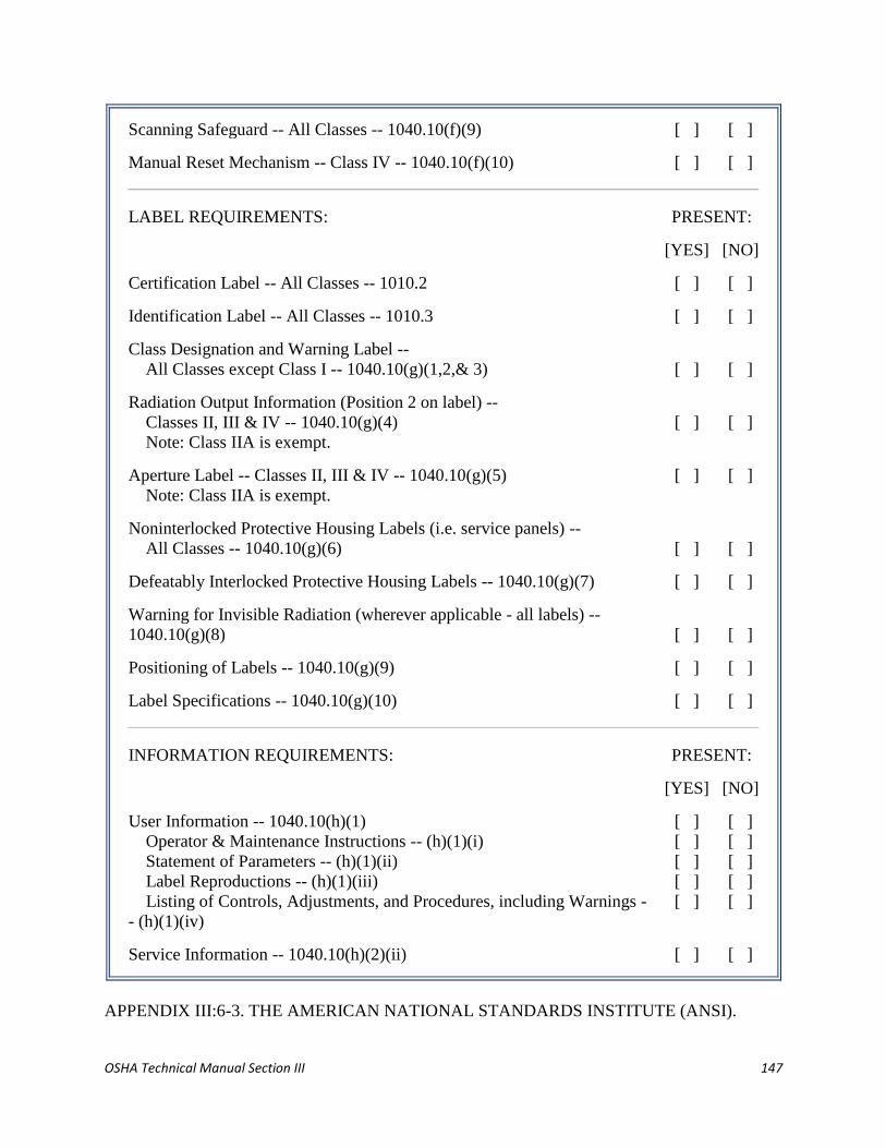
OSHA Technical Manual Section III 147
Scanning Safeguard -- All Classes -- 1040.10(f)(9) [ ] [ ]
Manual Reset Mechanism -- Class IV -- 1040.10(f)(10) [ ] [ ]
LABEL REQUIREMENTS: PRESENT:
[YES] [NO]
Certification Label -- All Classes -- 1010.2 [ ] [ ]
Identification Label -- All Classes -- 1010.3 [ ] [ ]
Class Designation and Warning Label --
All Classes except Class I -- 1040.10(g)(1,2,& 3) [ ] [ ]
Radiation Output Information (Position 2 on label) --
Classes II, III & IV -- 1040.10(g)(4)
Note: Class IIA is exempt.
[ ] [ ]
Aperture Label -- Classes II, III & IV -- 1040.10(g)(5)
Note: Class IIA is exempt.
[ ] [ ]
Noninterlocked Protective Housing Labels (i.e. service panels) --
All Classes -- 1040.10(g)(6) [ ] [ ]
Defeatably Interlocked Protective Housing Labels -- 1040.10(g)(7) [ ] [ ]
Warning for Invisible Radiation (wherever applicable - all labels) --
1040.10(g)(8) [ ] [ ]
Positioning of Labels -- 1040.10(g)(9) [ ] [ ]
Label Specifications -- 1040.10(g)(10) [ ] [ ]
INFORMATION REQUIREMENTS: PRESENT:
[YES] [NO]
User Information -- 1040.10(h)(1)
Operator & Maintenance Instructions -- (h)(1)(i)
Statement of Parameters -- (h)(1)(ii)
Label Reproductions -- (h)(1)(iii)
Listing of Controls, Adjustments, and Procedures, including Warnings -
- (h)(1)(iv)
[ ]
[ ]
[ ]
[ ]
[ ]
[ ]
[ ]
[ ]
[ ]
[ ]
Service Information -- 1040.10(h)(2)(ii) [ ] [ ]
APPENDIX III:6-3. THE AMERICAN NATIONAL STANDARDS INSTITUTE (ANSI).

OSHA Technical Manual Section III 148
An American National Standard implies a consensus of those substantially concerned with its
scope and provisions. These standards are intended as a guide to aid the manufacturer, the
consumer and the general public. There is, however, no inherent requirement for anyone or any
company to adhere to an ANSI standard. Compliance is voluntary unless specifically required by
some alliance. For example, the Federal Department of Energy requires adherence to the ANSI Z
136.1 by their internal staff as well as all contractor organizations. At present, the following
ANSI standards can be useful in laser safety matters:
ANSI Z 136.1 (1993): "FOR THE SAFE USE OF LASERS"
This is the master or "parent" standard in the Z 136 series. Originally published in 1973, this
standard has gone through revisions in 1976, 1980, 1986, and 1993. Revisions are currently
being considered by the committee for the next publication which should occur in 1991.
The Z 136.1 (1993) standard includes the basis of laser hazard assessment including the Nominal
Hazard Zone (NHZ) concept and measurements, establishes Maximum Permissible Exposure
(MPE) limits based on bioeffects of the eye and skin, introduces a general classification scheme,
specifies the recommended control measures, outlines suggested medical surveillance practice,
specifies training requirements and recommends practices for other (nonbeam) concerns.
ANSI Z 136.2 (1988): "FOR THE SAFE USE OF OPTICAL FIBER COMMUNICATION
SYSTEMS UTILIZING LASER DIODE AND LED SOURCES"
This ANSI Standard provides guidance for the safe use of optical fiber communications systems
(OFCS) utilizing laser diodes and/or LED sources by defining control measures for each of four
service group (SG) classifications. This concept eliminates measurements and/or calculations.
The standard is limited to OFCS that emit at power levels at or below 0.5 W.
The Z 136.2 standard addresses the same general topics as the base Z 136.1 standard. The
significant variation between the two standards lies in the definition of a Maximum Permissible
Irradiance (MPI) value based upon a 5 mm limiting aperture in the visible and near-infrared
spectral regions. This is in contrast to the larger 7mm limiting aperture used in this spectral
region in the ANSI Z 136.1 Standard.
ANSI Z 136.3 (1988): "FOR THE SAFE USE OF LASERS IN HEALTH CARE FACILITIES"
The ANSI Z 136.3 Standard provides guidance for the safe use of lasers for diagnostic and
therapeutic uses in health care facilities. The publication includes an extensive appendix that
details suggested practice in fourteen medical subspecialty areas. (Although the appendix is not
technically a part of the standard.)
Major emphasis is included on the associated hazard topics of airborne contaminants ("plume")
and electrical and fire hazards. The information in the base of the standard has been kept less
mathematical and refers the reader frequently to the ANSI Z 136.1 Standard if such detail is
needed. Summary charts provide information on MPE and NHZ values. Control measures are
identical, in most cases, to the master standards, with items special to medical laser systems (foot
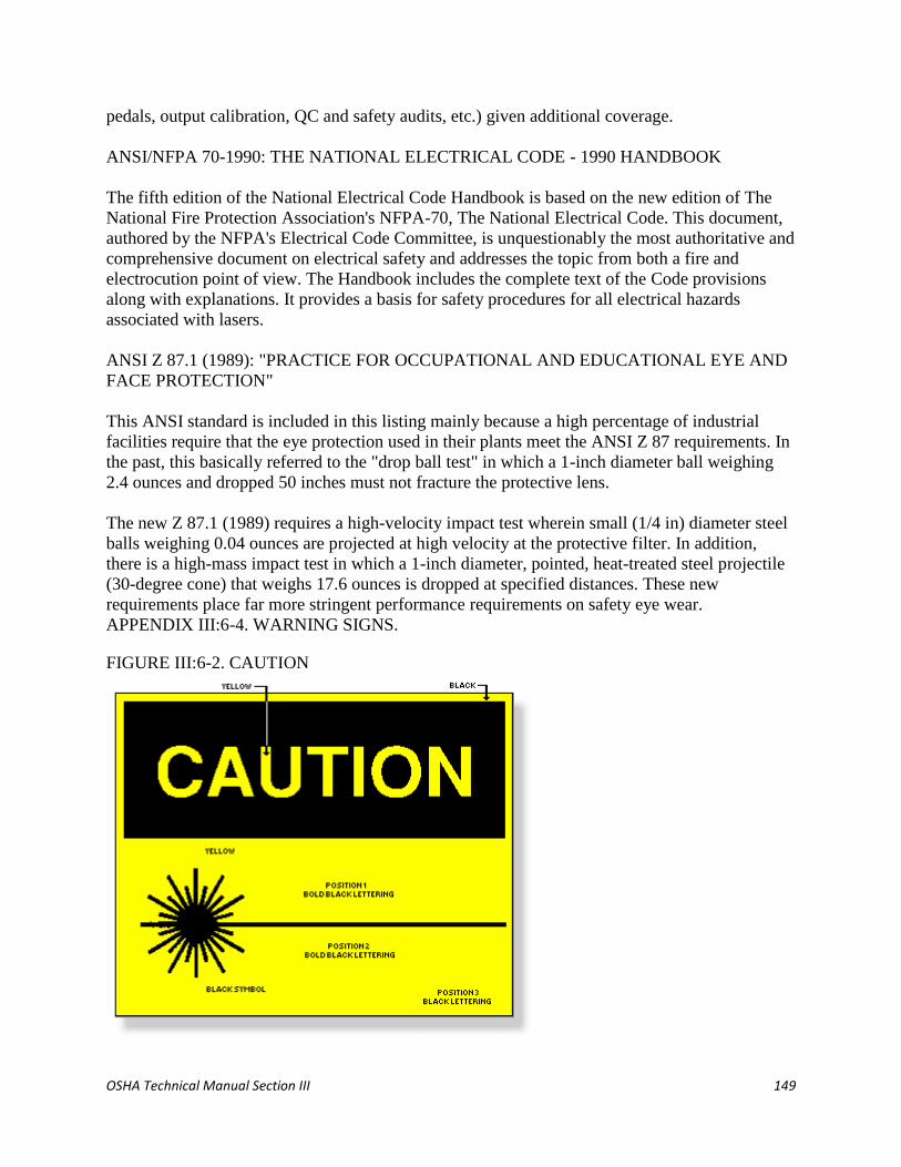
OSHA Technical Manual Section III 149
pedals, output calibration, QC and safety audits, etc.) given additional coverage.
ANSI/NFPA 70-1990: THE NATIONAL ELECTRICAL CODE - 1990 HANDBOOK
The fifth edition of the National Electrical Code Handbook is based on the new edition of The
National Fire Protection Association's NFPA-70, The National Electrical Code. This document,
authored by the NFPA's Electrical Code Committee, is unquestionably the most authoritative and
comprehensive document on electrical safety and addresses the topic from both a fire and
electrocution point of view. The Handbook includes the complete text of the Code provisions
along with explanations. It provides a basis for safety procedures for all electrical hazards
associated with lasers.
ANSI Z 87.1 (1989): "PRACTICE FOR OCCUPATIONAL AND EDUCATIONAL EYE AND
FACE PROTECTION"
This ANSI standard is included in this listing mainly because a high percentage of industrial
facilities require that the eye protection used in their plants meet the ANSI Z 87 requirements. In
the past, this basically referred to the "drop ball test" in which a 1-inch diameter ball weighing
2.4 ounces and dropped 50 inches must not fracture the protective lens.
The new Z 87.1 (1989) requires a high-velocity impact test wherein small (1/4 in) diameter steel
balls weighing 0.04 ounces are projected at high velocity at the protective filter. In addition,
there is a high-mass impact test in which a 1-inch diameter, pointed, heat-treated steel projectile
(30-degree cone) that weighs 17.6 ounces is dropped at specified distances. These new
requirements place far more stringent performance requirements on safety eye wear.
APPENDIX III:6-4. WARNING SIGNS.
FIGURE III:6-2. CAUTION

OSHA Technical Manual Section III 150
FIGURE III:6-3. DANGER
FIGURE III:6-4. LASER REPAIR NOTICE
APPENDIX III:6-5. GLOSSARY OF LASER TERMS.
Absorb To transform radiant energy into a different form, with a resultant rise in temperature.
Absorption Transformation of radiant energy to a different form of energy by the interaction of
matter, depending on temperature and wavelength.

OSHA Technical Manual Section III 151
Accessible Emission Level The magnitude of accessible laser (or collateral) radiation of a
specific wavelength or emission duration at a particular point as measured by appropriate
methods and devices. Also means radiation to which human access is possible in accordance
with the definitions of the laser's hazard classification.
Accessible Emission Limit (AEL) The maximum accessible emission level permitted within a
particular class. In ANSI Z 136.1, AEL is determined as the product of accessible emission
Maximum Permissible Exposure limit (MPE) and the area of the limiting aperture (7 mm for
visible and near-infrared lasers).
Aperture An opening through which radiation can pass.
Argon A gas used as a laser medium. It emits blue-green light primarily at 448 and 515 nm.
Attenuation The decrease in energy (or power) as a beam passes through an absorbing or
scattering medium.
Aversion Response Movement of the eyelid or the head to avoid an exposure to a noxious
stimulant, bright light. It can occur within 0.25 seconds, and it includes the blink reflex time.
Beam A collection of rays that may be parallel, convergent, or divergent.
Beam Diameter The distance between diametrically opposed points in the cross section of a
circular beam where the intensity is reduced by a factor of e-1
(0.368) of the peak level (for safety
standards). The value is normally chosen at e-2
(0.135) of the peak level for manufacturing
specifications.
Beam Divergence Angle of beam spread measured in radians or milliradians (1 milliradian =
3.4 minutes of arc or approximately 1 mil). For small angles where the cord is approximately
equal to the arc, the beam divergence can be closely approximated by the ratio of the cord length
(beam diameter) divided by the distance (range) from the laser aperture.
Blink Reflex See aversion response.
Brightness The visual sensation of the luminous intensity of a light source. The brightness of a
laser beam is most closely associated with the radio-metric concept of radiance.
Carbon Dioxide Molecule used as a laser medium. Emits far energy at 10,600 nm (10.6 µm).
Closed Installation Any location where lasers are used which will be closed to unprotected
personnel during laser operation.
CO2 Laser A widely used laser in which the primary lasing medium is carbon dioxide gas. The
output wavelength is 10.6 µm (10600 nm) in the far infrared spectrum. It can be operated in
either CW or pulsed.

OSHA Technical Manual Section III 152
Coherence A term describing light as waves which are in phase in both time and space.
Monochromaticity and low divergence are two properties of coherent light.
Collimated Light Light rays that are parallel. Collimated light is emitted by many lasers.
Diverging light may be collimated by a lens or other device.
Collimation Ability of the laser beam to not spread significantly (low divergence) with distance.
Continuous Mode The duration of laser exposure is controlled by the user (by foot or hand
switch).
Continuous Wave (CW) Constant, steady-state delivery of laser power.
Controlled Area Any locale where the activity of those within are subject to control and
supervision for the purpose of laser radiation hazard protection.
Diffuse Reflection Takes place when different parts of a beam incident on a surface are
reflected over a wide range of angles in accordance with Lambert's Law. The intensity will fall
off as the inverse of the square of the distance away from the surface and also obey a Cosine
Law of reflection.
Divergence The increase in the diameter of the laser beam with distance from the exit aperture.
The value gives the full angle at the point where the laser radiant exposure or irradiance is e-1
or
e-2
of the maximum value, depending upon which criteria is used.
Embedded Laser A laser with an assigned class number higher than the inherent capability of
the laser system in which it is incorporated, where the system's lower classification is appropriate
to the engineering features limiting accessible emission.
Emission Act of giving off radiant energy by an atom or molecule.
Enclosed Laser Device Any laser or laser system located within an enclosure which does not
permit hazardous optical radiation emission from the enclosure. The laser inside is termed an
"embedded laser."
Energy (Q) The capacity for doing work. Energy is commonly used to express the output from
pulsed lasers and it is generally measured in Joules (J). The product of power (watts) and
duration (seconds). One watt second = one Joule.
Excimer "Excited Dimer" A gas mixture used as the active medium in a family of lasers
emitting ultraviolet light.
Fail-safe Interlock An interlock where the failure of a single mechanical or electrical
component of the interlock will cause the system to go into, or remain in, a safe mode.
OSHA Technical Manual Section III 153
Gas Discharge Laser A laser containing a gaseous lasing medium in a glass tube in which a
constant flow of gas replenishes the molecules depleted by the electricity or chemicals used for
excitation.
Gas Laser A type of laser in which the laser action takes place in a gas medium.
Helium-Neon (HeNe) Laser A laser in which the active medium is a mixture of helium and
neon. Its wavelength is usually in the visible range. Used widely for alignment, recording,
printing, and measuring.
Infrared Radiation (IR) Invisible electromagnetic radiation with wavelengths which lie within
the range of 0.70 to 1000 µm. These wavelengths are often broken up into regions: IR-A (0.7-1.4
µm), IR-B (1.4-3.0 µm) and IR-C (3.0-1000 µm).
Intrabeam Viewing The viewing condition whereby the eye is exposed to all or part of a direct
laser beam or a specular reflection.
Irradiance (E) Radiant flux (radiant power) per unit area incident upon a given surface. Units:
Watts per square centimeter. (Sometimes referred to as power density, although not exactly
correct).
Laser An acronym for light amplification by stimulated emission of radiation. A laser is a
cavity with mirrors at the ends, filled with material such as crystal, glass, liquid, gas or dye. It
produces an intense beam of light with the unique properties of coherency, collimation, and
monochromaticity.
Laser Accessories The hardware and options available for lasers, such as secondary gases,
Brewster windows, Q-switches and electronic shutters.
Laser Controlled Area See Controlled Area.
Laser Device Either a laser or a laser system.
Laser Medium (Active Medium)Material used to emit the laser light and for which the laser is
named.
Laser Rod A solid-state, rod-shaped lasing medium in which ion excitation is caused by a
source of intense light, such as a flash lamp. Various materials are used for the rod, the earliest of
which was synthetic ruby crystal.
Laser Safety Officer (LSO) One who has authority to monitor and enforce measures to control
laser hazards and effect the knowledgeable evaluation and control of laser hazards.
Laser System An assembly of electrical, mechanical and optical components which includes a
laser. Under the Federal Standard, a laser in combination with its power supply (energy source).

OSHA Technical Manual Section III 154
Lens A curved piece of optically transparent material which, depending on its shape, is used to
either converge or diverge light.
Light The range of electromagnetic radiation frequencies detected by the eye, or the wavelength
range from about 400 to 760 nm. The term is sometimes used loosely to include radiation beyond
visible limits.
Limiting Aperture The maximum circular area over which radiance and radiant exposure can be
averaged when determining safety hazards.
Maintenance Performance of those adjustments or procedures specified in user information
provided by the manufacturer with the laser or laser system, which are to be performed by the
user to ensure the intended performance of the product. It does not include operation or service
as defined in this glossary.
Maximum Permissible Exposure (MPE) The level of laser radiation to which a person may be
exposed without hazardous effect or adverse biological changes in the eye or skin.
Nd:Glass Laser A solid-state laser of neodymium:glass offering high power in short pulses. A
Nd-doped glass rod used as a laser medium to produce 1064 nm light.
Nd:YAG Laser Neodymium:Yttrium Aluminum Garnet. A synthetic crystal used as a laser
medium to produce 1064 nm light.
Neodymium (Nd) The rare earth element that is the active element in Nd:YAG laser and
Nd:Glass lasers.
Nominal Hazard Zone (NHZ) The nominal hazard zone describes the space within which the
level of the direct, reflected or scattered radiation during normal operation exceeds the applicable
MPE. Exposure levels beyond the boundary of the NHZ are below the appropriate MPE level.
Optical Cavity (Resonator) Space between the laser mirrors where lasing action occurs.
Optical Density A logarithmic expression for the attenuation produced by an attenuating
medium, such as an eye protection filter.
Optical Fiber A filament of quartz or other optical material capable of transmitting light along
its length by multiple internal reflection and emitting it at the end.
Optical Pumping The excitation of the lasing medium by the application of light rather than
electrical discharge.
Optical Radiation Ultraviolet, visible, and infrared radiation (0.35-1.4 µm) that falls in the
region of transmittance of the human eye.
Output Power The energy per second measured in watts emitted from the laser in the form of
OSHA Technical Manual Section III 155
coherent light.
Power The rate of energy delivery expressed in watts (Joules per second). Thus: 1 Watt = 1
Joule × 1 §
Protective Housing A protective housing is a device designed to prevent access to radiant power
or energy.
Pulse A discontinuous burst of laser, light or energy, as opposed to a continuous beam. A true
pulse achieves higher peak powers than that attainable in a CW output.
Pulse Duration The "on" time of a pulsed laser, it may be measured in terms of milliseconds,
microseconds, or nanoseconds as defined by half-peak-power points on the leading and trailing
edges of the pulse.
Pulsed Laser Laser which delivers energy in the form of a single or train of pulses.
Pump To excite the lasing medium. See Optical Pumping or Pumping.
Pumped Medium Energized laser medium.
Pumping Addition of energy (thermal, electrical, or optical) into the atomic population of the
laser medium, necessary to produce a state of population inversion.
Radiant Energy (Q) Energy in the form of electromagnetic waves usually expressed in units of
Joules (watt-seconds).
Radiant Exposure (H) The total energy per unit area incident upon a given surface. It is used to
express exposure to pulsed laser radiation in units of J/cm2.
Reflection The return of radiant energy (incident light) by a surface, with no change in
wavelength.
Refraction The change of direction of propagation of any wave, such as an electromagnetic
wave, when it passes from one medium to another in which the wave velocity is different. The
bending of incident rays as they pass from one medium to another (e.g., air to glass).
Resonator The mirrors (or reflectors) making up the laser cavity including the laser rod or tube.
The mirrors reflect light back and forth to build up amplification.
Ruby The first laser type; a crystal of sapphire (aluminum oxide) containing trace amounts of
chromium oxide.
Scanning Laser A laser having a time-varying direction, origin or pattern of propagation with
respect to a stationary frame of reference.

OSHA Technical Manual Section III 156
Secured Enclosure An enclosure to which casual access is impeded by an appropriate means
(e.g., door secured by lock, magnetically or electrically operated latch, or by screws).
Semiconductor Laser A type of laser which produces its output from semiconductor materials
such as GaAs.
Service Performance of adjustments, repair or procedures on a non-routine basis, required to
return the equipment to its intended state.
Solid Angle The ratio of the area on the surface of a sphere to the square of the radius of that
sphere. It is expressed in steradians (sr).
Source The term source means either laser or laser-illuminated reflecting surface, i.e., source of
light.
Tunable Laser A laser system that can be "tuned" to emit laser light over a continuous range of
wavelengths or frequencies.
Tunable Dye Laser A laser whose active medium is a liquid dye, pumped by another laser or
flash lamps, to produce various colors of light. The color of light may be tuned by adjusting
optical tuning elements and/or changing the dye used.
Ultraviolet (UV) Radiation Electromagnetic radiation with wavelengths between soft X-rays
and visible violet light, often broken down into UV-A (315-400 nm), UV-B (280-315 nm), and
UV-C (100-280 nm).
Visible Radiation (light) Electromagnetic radiation which can be detected by the human eye. It
is commonly used to describe wavelengths in the range between 400 nm and 700-780 nm.
Wavelength The length of the light wave, usually measured from crest to crest, which
determines its color. Common units of measurement are the micrometer (micron), the nanometer,
and (earlier) the Angstrom unit.
YAG Yttrium Aluminum Garnet, a widely used solid-state crystal composed of yttrium and
aluminum oxides and a small amount of the rare earth neodymium.

OSHA Technical Manual Section III 157
SECTION III: CHAPTER 7
LEGIONNAIRES' DISEASE
Contents:
I.
II.
III.
IV.
V.
VI.
Introduction
Disease Recognition
Source Identification
Investigation Protocol
Controls
Bibliography
Appendix III:7-1. Employee Awareness Program
Appendix III:7-2. Physical Survey and Water Sampling Protocol
Appendix III:7-3. Water Sampling Guidelines
Appendix III:7-4. Legionnaires' Disease Case Identification
Appendix III:7-5. Water Treatment Protocols for Facilities That Have Experienced a
Legionnaires' Outbreak
I. INTRODUCTION.
This chapter provides information to assist industrial hygienists in the assessment of work
sites for potential Legionnaires' disease. It provides information on disease recognition,
investigation procedures to identify probable water sources, and control strategies. The
primary focus of this document is on the control and prevention of contaminated water
sources, not on case identification, an area of expertise primarily exercised by local
health departments frequently in conjunction with the Centers for Disease Control and
Prevention (CDC) in Atlanta. Appendices include details on conducting an employee
awareness program, water sampling protocols and guidelines for acceptable levels of the
organism in water, procedures for identifying new cases of the disease, and water
treatment and control strategies for facilities where an outbreak has occurred.
II. DISEASE RECOGNITION.
A. CAUSATIVE AGENT.
1. Legionella pneumophila was first identified in 1977 by the CDC as the
cause of an outbreak of pneumonia that caused 34 deaths at a 1976
American Legion Convention in Philadelphia. L. pneumophila had

OSHA Technical Manual Section III 158
undoubtedly caused previous pneumonia outbreaks, but the organism's
slow growth and special growth requirements prevented earlier discovery.
2. The diseases produced by Legionella are called legionellosis. More than
34 species of Legionella have been identified, and more than 20 linked
with human diseases. L. pneumophila causes the pneumonia known as
Legionnaires' disease and the flu-like Pontiac fever. L. pneumophila has
also been implicated in wound infections, pericarditis, and endocarditis
without the presence of pneumonia. Because the majority of legionellosis
is caused by L. pneumophila, this chapter will deal exclusively with that
organism. Cases where other species of Legionella are involved in disease
require actions similar to those to control Legionnaires' disease.
3. The L. pneumophila bacteria are gram-negative rods that exist in a number
of distinguishable serogroups. Each serogroup contains further subtypes
that have different surface structures on the cell membrane and can be
distinguished by special tests. Evidence indicates that some Legionella
serogroups are more virulent than others. L. pneumophila serogroup 1 is
the most frequently identified form of the bacterium isolated from patients
with Legionnaires' disease, although other serogroups and subtypes of the
bacterium are frequently isolated from water sources. Serogroups 4 and 6
are the next most frequently linked with disease.
B. SYMPTOMS.
1. Legionnaires' disease has an incubation period of two to ten days. Severity
ranges from a mild cough and low fever to rapidly progressive pneumonia
and coma. Early symptoms include malaise, muscle aches, and slight
headache. Later symptoms include high fever (up to 105°F), a dry cough,
and shortness of breath. Gastrointestinal symptoms including vomiting,
diarrhea, nausea, and abdominal pain are common. The disease is treated
with erythromycin or a combination of erythromycin and rifampin.
2. Pontiac fever is a non-pneumonia, flu-like disease associated with, and
likely caused by, the Legionella bacterium. This disease has an "attack
rate" of 90% or higher among those exposed, and a short incubation
period, 1-3 days. Complete recovery usually occurs in 2-5 days without
medical intervention. The factors that cause the same organism to produce
two illnesses with major differences in attack rate and severity are not
known.
C. INCIDENCE. In the U.S., Legionnaire's disease is considered to be fairly
common and serious, and the Legionella organism is one of the top three causes

OSHA Technical Manual Section III 159
of sporadic, community-acquired pneumonia. Because it is difficult to distinguish
this disease from other forms of pneumonia, many cases go unreported.
Approximately 1,000 cases are reported annually to the CDC, but it is estimated
that over 25,000 cases of the illness occur each year and cause more than 4,000
deaths.
D. RISK FACTORS. Legionnaires' disease is frequently characterized as an
"opportunistic" disease that most frequently attacks individuals who have an
underlying illness or weakened immune system. The most susceptible include
persons who are elderly, smokers, and immunosuppressed. Individuals with
chronic obstructive pulmonary disease (COPD), organ transplant patients, and
persons taking corticosteroid therapy are also at elevated risk. The attack rate for
the average population is approximately 5% or less. The fatality rate is similar to
that of other forms of pneumonia, approximately 15%.
E. DIAGNOSIS. CDC guidelines define two types of cases of Legionelloses,
probable and confirmed. A probable case of Legionnaire's disease is a person who
experienced an illness clinically compatible with Legionnaire's and has a single
antibody titer of 256 or higher (discussed below), and can be associated with a
population of individuals who have experienced confirmed cases of the disease
(outbreak). A confirmed case of Legionella requires a physician's diagnosis of
pneumonia based on a chest x-ray and positive laboratory test results. A
laboratory test is necessary for confirmation because the symptoms and x-ray
evidence of Legionnaires' disease resemble those of other types of pneumonia.
Various methods are used to confirm the presence of the disease.
1. Culture of the Organism. The definitive laboratory method of
confirming the presence of the disease is by culturing viable cells of
Legionella from sputum, bronchial washing, or autopsy on special media.
Further identification of the cultured cells will identify the species and
serogroup. Special tests may determine subtype of certain isolates. The
sensitivity of this test to detect the disease is reported to be about 70%.
2. Urine Antigen Test. The detection of antigen from L. pneumophila in the
urine is considered a reliable measure of the disease. These antigenic
materials may include L. pneumophila cells or portions of cells in the
urine during and after the disease. The presence of antigen in the urine is a
strong indicator of the disease, and a patient may have a positive response
for several months following the disease. The sensitivity of this test is
limited because the only commercially available urinary antigen test
detects only serogroup 1 forms of L. pneumophila. The CDC recommends
only the radioimmunoassay (RIA) test because the latex antigen (LA) test
has a high false-positive rate. Fortunately, 80-90% of the clinically
diagnosed cases are caused by serogroup 1. The absence of a positive
urinary test is not proof that a patient did not have Legionnaires' disease,
but merely indicates the absence of antigen in the urine at the time of the
test.

OSHA Technical Manual Section III 160
3. Direct Fluorescent Antibody (DFA) Staining. Direct fluorescent
antibody staining of lung aspirates can detect L. pneumophila. However,
this test is frequently negative during the initial stages of the disease
because few organisms are present in the aspirate or sputum. This test also
requires an antigen-specific reagent. There are a multitude of serogroups
and subtypes of L. pneumophila, and a test will be negative if the exact
antigen-specific reagent is not included.
4. Serology (Antibody Titers).
a. An increase in the antibody level in the serum of infected persons
occurs several weeks after the onset of the disease. A fourfold increase in
the antibody titer coupled with a physician's diagnosis of pneumonia is
considered a reliable indicator of disease. This is measured by comparing
the antibody level four to eight weeks after onset (convalescent titer) to an
initial (acute) titer at the beginning of the disease. Pontiac fever also
produces an elevated antibody titer, but the flu-like symptoms of this
disease do not match those of Legionnaires' disease.
b. Frequently only a convalescent titer has been measured from
individuals who had symptoms of the disease. For situations in which
these cases are associated with an outbreak of Legionnaires' disease, a
single titer of 256 to 1 or higher is generally used as a presumptive
indication of disease (probable case). Antibody strength is determined by
the number of dilutions of serum which elicit a positive antibody response.
The reciprocal value of the number of dilutions is the antibody titer. For
example, an antibody titer of 256 means a positive antibody test of the
patients's serum following serial dilutions of 1:2, then 1:4, then 1:16, etc.,
until the 1:256 dilution point is reached.
c. The indirect fluorescent antibody (IFA) test is the accepted diagnostic
tool for demonstrating L. pneumophilia exposure. Another widely used
test of antibody response is the enzyme-linked immunosorbent assay
method (ELISA). CDC believes that direct comparison of results between
IFA and ELISA is not reliable because there are insufficient data to
compare the two. The ELISA method has gained wide medical acceptance
as a useful means of demonstrating exposure to Legionella.
F. TRANSMISSION.
1. The likelihood of contracting Legionnaires' disease is related to the level
of contamination in the water source, the susceptibility of the person
exposed, and the intensity of exposure to the contaminated water. Disease
transmission usually occurs via inhalation of an aerosol of water
contaminated with the organism. Aspiration of contaminated water into

OSHA Technical Manual Section III 161
the lungs may also cause the disease. In the Philadelphia Legionnaires'
disease outbreak, the hotel's cooling tower was identified as the likely
source of the disease, although domestic water sources were not evaluated.
2. The disease has been associated with domestic hot-water systems in a
number of outbreaks. In many instances it has been difficult to identify a
likely source for aerosolization of the suspected water source. Although
transmission of the disease other than through direct inhalation of aerosols
may occur, the mechanisms are not clearly understood. The organism
requires water, and the disease cannot occur in the absence of a
contaminated water source. There is no evidence that the disease can be
transmitted from one person to another.
III. SOURCE IDENTIFICATION.
A. CONDITIONS THAT PROMOTE GROWTH.
1. L. pneumophila bacteria are widely distributed in water systems. They
tend to grow in biofilms or slime on the surfaces of lakes, rivers and
streams, and they are not eradicated by the chlorination used to purify
domestic water systems. Low and even nondetectable levels of the
organism can colonize a water source and grow to high concentrations
under the right conditions.
Conditions that promote growth of the organism include heat, sediment,
scale, and supporting (commensal) microflora in water. Common water
organisms including algae, amoebae, and other bacteria appear to amplify
Legionella growth by providing nutrients or harboring the organism.
Because of its ability to remain viable in domestic water systems, it is
capable of rapid multiplication under the proper conditions.
2. Water conditions that tend to promote the growth of Legionella include:
stagnation;
temperatures between 20° and 50°C (68° - 122°F) (The optimal
growth range is 35° - 46°C [95° - 115°F]);
pH between 5.0 and 8.5;
sediment that tends to promote growth of commensal microflora;
and
micro-organisms including algae, flavobacteria, and Pseudomonas,
which supply essential nutrients for growth of Legionella or harbor
the organism (amoebae, protozoa).
B. COMMON SOURCES OF CONTAMINATED WATER.
1. Water sources that frequently provide optimal conditions for growth of the
organisms include:

OSHA Technical Manual Section III 162
cooling towers, evaporative condensers, and fluid coolers that use
evaporation to reject heat. These include many industrial processes
that use water to remove excess heat;
domestic hot-water systems with water heaters that operate below
60°C (140°F) and deliver water to taps below 50°C (122°F);
humidifiers and decorative fountains that create a water spray and
use water at temperatures favorable to growth;
spas and whirlpools;
dental water lines, which are frequently maintained at temperature
above 20°C (68°F) and sometimes as warm as 37°C (98.6°F) for
patient comfort; and
other sources including stagnant water in fire sprinkler systems and
warm water for eye washes and safety showers.
2. Water stored below 20°C (68°F) is generally not a source for amplified L.
pneumophila levels. However, high levels of bacteria have been measured
in the water supplying ice machines. The source of amplification in this
case was thought to be heat from the condenser coil of the ice maker to the
cold water supply. However, no cases of Legionnaires' disease have been
linked to consumption of ice made from contaminated water.
C. MONITORING.
1. Air. An air sample applied to special culture plates by an Andersen-type
sampler sometimes demonstrates the presence of the organism in the air.
However, negative results are frequent because of the difficulty in
maintaining viability of the organism on the culture plates. Air sampling
for Legionella is strongly not recommended as a means of measuring
potential exposure because of the high likelihood of false negatives.
2. Water. Analysis of water samples from a source suspected of being
contaminated with L. pneumophila is a valuable means of identifying
potential sources of the disease. A qualified microbiological laboratory
experienced in Legionella detection can determine the number of
organisms present in colony forming units (CFU) per volume of water and
can identify the different serogroups of Legionella pneumophila in the
sample. Appendix III:7-2 provides details on the collection, storage, and
shipping of water samples.
D. MICROBIOLOGICAL ANALYSIS OF WATER SAMPLES.
1. Cultured Samples. Water samples are cultured on special buffered
charcoal yeast extract (BCYE) culture media. Selective isolation processes
OSHA Technical Manual Section III 163
to eliminate other microbial overgrowth can determine the number of CFU
of L. pneumophila per milliliter of water. This process of growth and
isolation is time-consuming, and results typically require 7-14 days from
the time of submission.
Cultured samples can also be analyzed to identify specific serogroups.
Matching the same serogroup and subtype of organism in the patient as
found in a water source is considered strong evidence of an associated
link.
2. Direct Fluorescence Antibody (DFA). The number of organisms in a
water sample can also be determined via direct fluorescence antibody
(DFA) conjugate tests that stain the organism with a fluorescent dye. This
test is unable to distinguish between live and dead bacteria and may also
have some cross-reactivity with other bacteria. Sample results can be
available in one or two days, and this method can be useful in screening
water samples. Use caution, however, in interpreting the results since the
potential exists for both false positive and negative results.
3. DNA Amplification. A relatively new method for rapid, specific detection
of the organism in water employs a polymerase chain reaction (PCR)
process to amplify and then detect portions of DNA unique to L.
pneumophila. This method can produce results in 1 day, and preliminary
evidence indicates that its sensitivity and specificity are comparable to
those of cell culture, which can take 10-14 days to obtain results. Further
testing may lead to acceptance of this technique as the method of choice
for monitoring water sources for contamination.
E. INTERPRETATION OF SAMPLE RESULTS.
1. The probability of infection with L. pneumophila is a function both of the
intensity of the exposure dose and the level of host susceptibility. Because
total eradication of Legionella may not be possible, an acceptable control
strategy is to minimize the number of organisms present in a water source.
Ample evidence indicates that Legionella levels are readily controllable. A
survey of over 1,000 cooling towers indicates that approximately 60%
contained nondetectable levels of L. pneumophila when measured by DFA
analysis for the number of organisms per milliliter of water (detection
limit is 10 bacteria per milliliter of water). In another survey of 663
cooling towers, 57% contained Legionella that were not detected when
measured by culture (detection limit less than 1 CFU/mL). Other studies
of domestic hot-water sources indicate that although the organism is
common, especially in large hot-water systems, practical control measures
can limit the potential for amplification.
OSHA Technical Manual Section III 164
2. A private consulting firm and microbiological laboratory, PathCon Inc. of
Norcross, Georgia, has introduced suggested guidelines for control of the
organism based on the number of CFU of L. pneumophila per milliliter of
water (Appendix III:7-3.) These guidelines vary depending on the water
source, a recognition by the authors that dose is related both to the
potential for exposure and to concentration. For example, recommended
exposure limits for contaminated water from a humidifier, which would
involve direct exposure to an aerosol are lower than for a cooling tower
where the opportunity for exposure is normally less. Work operations such
as maintenance on cooling towers may involve direct exposure to cooling
tower mist, and precautions to minimize exposure are always necessary.
The authors recognize that these guidelines are based on limited data, but
they represent the best available information and must suffice until the
dose effect of L. pneumophila is better understood.
IV. INVESTIGATION PROTOCOL.
A. COMMUNITY HEALTH CONCERNS. It is important to remember that an
outbreak of Legionnaires' disease among workers may have its origin in the
community and may not be related to the work environment. A Legionnaires'
outbreak is both an occupational and a public-health concern, and the
investigation may include local public health departments and the Centers for
Disease Control (CDC). To minimize employee risk and maximize the
effectiveness of effort, close coordination among OSHA, other public agencies,
and the employer is imperative.
B. TYPES OF INVESTIGATIONS.
1. The course of action chosen during an investigation of a facility should be
based on the degree of certainty that the site is the source of a reported
illness. For this reason, two investigation protocols are based on differing
levels of suspected risk for exposure to Legionella. It is important to
remember that these procedures are provided only to assist in the
investigation of potential Legionnaires' cases. Individual circumstances
may require changes in the investigation. All cases require sound
professional judgment in deciding the appropriate course of action.
2. A level-one investigation may be initiated when there is a probable basis
for suspecting that workplace water sources are contaminated with
Legionella, or when there is information that one case of Legionnaires'
disease may exist. A level-two investigation should be conducted when
more then one possible case of Legionnaires' disease has been reported at
a facility.
3. If two or more cases of the disease can be attributed to a work site, assume
that a Legionnaires' disease outbreak has occurred. If evidence indicates
that the outbreak is still in progress (that is, at least one of the cases has

OSHA Technical Manual Section III 165
occurred in the last 30 days), prompt actions should be undertaken to
provide maximum protection to employees and eliminate the hazard.
Appendix III:7-5 includes examples of actions required to control water
sources where an outbreak has occurred.
4. Both investigations follow the same general pattern and include a
preliminary opening conference, a walk-through of the facility to conduct
a physical assessment of the water systems, a more detailed examination
of the systems including a review of maintenance records, assessment of
findings, and a closing conference to present control actions based on the
findings.
C. LEVEL-ONE INVESTIGATION. Use the following procedure when
Legionnaires' disease may be related to the work environment.
1. Step 1. Obtain an overview of all water systems at the facility.
a. A facilities engineer or experienced member of the building
maintenance staff should be available to explain system operation and
assist in the walkthrough investigation. This person should have a working
knowledge of the system's design and current operation.
b. The overview of the water systems should include plumbing systems,
heating-ventilating-air-conditioning (HVAC) systems, and other water
reservoirs. A review of the plumbing system should include both hot and
cold domestic water systems, water heaters, distribution pipes, water
coolers, water treatment equipment, connections to process water systems
protected (or unprotected) by backflow preventers, and storage tanks.
c. The HVAC system review should include cooling towers, evaporative
condensers, fluid coolers, humidifiers, direct evaporative air-cooling
equipment, indirect evaporative air-cooling equipment, air washers for
filtration, etc. Note the location of the fresh-air intakes of the building's
air-handling units relative to water sources such as the cooling towers.
d. Investigate other potential sources of employee exposure including
decorative fountains, plant misters, whirlpools, spas, tepid-water eye-
washes and safety showers, humidifiers, and water for cooling industrial
processes.
e. Review maintenance records on water systems including water heaters
and cooling towers. The records should include temperature checks of
domestic water, visual and physical checks of cooling towers, and reports
of cooling-tower water-quality assessment and chemical treatment.

OSHA Technical Manual Section III 166
f. Identify the locations of portions of the system in which water is
allowed to stagnate such as storage tanks or unused plumbing pipe
sections ("dead legs"), or infrequently used faucets. Check for cross-
connections between domestic and process water systems, and note the
condition and type of back-flow prevention devices.
g. Investigate recent major maintenance or changes in the system's
operation. Determined if there were recent or frequent losses of water
pressure from the incoming water supply due to line breakage or street
repairs. The failure of a back-flow prevention device under loss of
pressure can contaminate the system.
2. Step 2. Conduct a walk-through investigation of the facility.
a. Equipment you will need includes a thermometer for measuring water
temperatures, a flashlight, and a film or video camera to record
observations. Measure and record the temperature of water drawn from
each storage-type water heater in the facility. This temperature may be
significantly below the water heater's gauge temperature because of heat
stratification. Note the presence of rust and scale in this water.
b. Record the maximum temperature of water at faucets connected to each
water heater on the system. Record temperatures at locations near,
intermediate, and distant from the heaters. It may be necessary to run the
water for several minutes before it reaches a temperature maximum.
c. Examine the water temperature and the potential for stagnation of cold-
water storage tanks used for reserve capacity or to maintain hydrostatic
pressure. These should be protected from temperature extremes and
covered to prevent contamination. Record the temperature of the domestic
cold-water lines at various locations within the facility. Note both the
initial temperature and the final equilibrium temperature on the cold-water
line, and record the time required to reach equilibrium, because this can be
an indicator of the amount of stagnation in the system.
d. Evaluate cooling towers, evaporative condensers, and fluid coolers for
biofilm growth, scale buildup, and turbidity. Record the location of the
tower relative to fresh-air intakes, kitchen exhausts, leaves, plant material,
or other sources of organic material that might contribute to the growth of
the organism.
e. Record the general condition of the cooling tower. Determine the
presence and condition of drift eliminators, which are designed to limit the
vapor release from the units, along with the basin temperature of the water
in the cooling tower if it is currently being operated. If the cooling tower is
operating and is suspected of being contaminated, wear appropriate
respiratory protection in the form of a half-face piece respirator equipped

OSHA Technical Manual Section III 167
with a HEPA or similar type of filter capable of effectively collecting one-
micron particles during the examination of the system.
f. Note the location and evaluate the condition of the sumps for the
cooling tower(s), evaporative condenser(s), and fluid cooler(s). These
sumps are sometimes located indoors to protect them from freezing.
Record the locations of any cross-connections between the cooling tower
water system and any domestic water system. These may supply a back-up
source of cool water to refrigeration condenser units or serve to supply
auxiliary cooling units. The lack of a regular maintenance schedule or
water-treatment program for a cooling tower or evaporative condenser
system strongly suggests a potential for Legionella contamination.
3. Step 3. Assess the results of the walkthrough investigation to determine
the course of action. If no potential problems are identified, the operating
temperatures measured at water heaters are 60°C (140°F) or above, and
the delivery temperature at distant faucets is 50°C (122°F) or higher, no
further action will be necessary. However, if the system is poorly
maintained and operating temperatures are below recommended
minimums, then recommendations for corrective action should be made.
4. Step 4. Recommend control actions.
a. Details of suggested control actions are discussed in Section E. These
actions may include disinfection of the domestic water system via heat
treatment, chlorination, or other means, and cleaning and disinfecting the
cooling tower system according to the Wisconsin Division of Health
protocol for "Control of Legionella in Cooling Towers" or a similar
process for cleaning heat rejection systems that follows sound practices to
minimize potential for Legionella growth.
b. Additional actions may include eliminating dead legs in the plumbing
system, insulating plumbing lines and installing heat tracing to maintain
proper temperatures in the system, eliminating rubber gaskets, and
removing or frequently cleaning fixtures such as aerators and shower
heads.
c. Corrective actions limited to raising the water heater temperature
without evaluating the system for points of stagnation, heat loss and gain,
cross-contamination, and other factors that contribute to growth are
generally not sufficient.
d. For a level-one investigation it is not recommended that water samples
be collected to confirm the presence of Legionella in the system. The
absence of proper operating conditions alone is sufficient for assuming
that the water system can pose an unnecessary risk to the employees. Take
water samples after the completion of the control actions to confirm that

OSHA Technical Manual Section III 168
the corrective measures were successful. The employer may also want to
obtain samples before starting corrective actions to assess the extent of the
problem.
e. The employer should take necessary corrective actions even if the
results of presampling are negative. Water sampling can produce false
negatives, a contaminated portion of the system may have been missed,
and the absence of Legionella organisms at the time of sampling does not
insure that the system will remain negative.
f. If, after control actions, the Legionella levels in a water source exceed
the guidelines in Appendix III:7-3, re-examine the water system to
determine if potential contamination points within the system were
overlooked and reassess control procedures to determine if they were
performed properly. Repeat the procedures as needed until contamination
levels meet the guidelines.
D. LEVEL-TWO INVESTIGATION. A level-two investigation is similar to a
level-one investigation with several additional steps. Supplemental actions
include: (1) medical surveillance of all employees currently on sick leave to
identify any new cases, (2) employee awareness training on the disease to
minimize employee concerns and aid in early recognition of new cases, (3)
assessment of past sick-leave absences for undetected cases of the disease, and (4)
collection of water samples during the walkthrough assessment.
1. Step 1. Assess water systems as described for a level-one investigation.
2. Step 2. Conduct a second walkthrough survey of the facility and collect
water samples. Estimate the size of the building and the number of water
services during the initial walkthrough and prearrange supply and shipping
of the required number of sterile sample containers with the appropriate
laboratory. (See Appendix III:7-2 for water sampling procedures.)
3. Step 3. Initiate an employee awareness program and monitor current sick
leave for new cases. It is important to ensure that employees understand
the early symptoms of the disease and seek medical assistance promptly. It
is imperative not to alarm the workers. It is equally important to stress the
importance of the need to know the health status of all employees on sick
leave. (See Appendix III:7-1, Employee Awareness Program.)
4. Step 4. Review worker absences to detect other cases. This requires
identification of all employees who took three or more consecutive days of
sick leave from approximately six weeks before the case of Legionnaires'
disease was identified up to the present. Request those employees who
may have had pneumonia during this period to undergo additional

OSHA Technical Manual Section III 169
voluntary tests for evidence of Legionnaires' disease. (See Appendix III:7-
4, Case Identification.)
5. Step 5. Assess results of worker absence survey and analysis of water
systems. If evidence indicates more than one case of Legionnaires' disease
at the workplace, then the site should be treated as having an outbreak.
Take immediate control of all water sources to eliminate potential for
exposure, and take measures to eliminate the hazard. (See Appendix III:7-
5.)
No action is necessary if the results of the investigation are negative, that
is, (1) all water and HVAC systems are well maintained and in good
operating condition; (2) all water sample results are negative or acceptably
low (Appendix III:7-3); and (3) no new cases of the disease have been
identified at the work site. Under these circumstances, assume that the site
is not the origin of the identified case.
6. Step 6. For recommended control actions, see the level-one investigation.
7. Ongoing Outbreak.
a. If the evidence indicates that two or more cases of Legionnaires'
disease have occurred at a site, and at least one of the cases was within the
last 30 days, assume that an outbreak is in progress and requires a high-
priority investigation and prompt action. Conduct a level-two investigation
as outlined above, and take the following precautions to protect building
occupants.
b. Immediately initiate control measures to prevent additional exposures
to all water systems that have a reasonable potential for worker exposure
including hot and cold domestic water, cooling towers, humidifiers, and
any other potential sources of water exposure. Collect appropriate water
samples to determine Legionella levels before shutting down the water
systems (Appendix III:7-2). These sample results will be invaluable in
establishing the cause of the outbreak. A member of the building
maintenance or engineering staff who has a working knowledge of the
system's design and current operation can explain how the water system
operates and the proper procedure for a controlled shutdown.
These control actions need not require facility shutdown. Temporary
provisions can allow work to continue: bottled water can be supplied for
drinking, shutting off water heaters can eliminate hot-water access, and
temporary cooling towers can allow work to continue.
V. CONTROLS.
OSHA Technical Manual Section III 170
A. GENERAL DISCUSSION. This section contains background information on
water system operations and proper controls to prevent Legionella amplification.
This discussion encompasses a variety of water systems, some of which have not
been implicated with outbreaks of Legionnaires' disease. Nevertheless, it is
important to remember that any water system can be a source of disease if the
water in it is subjected to conditions that promote growth of the organism.
Remember, however, that the primary sources of exposure to contaminated water
are heat rejection systems (cooling towers, fluid coolers, etc.) and domestic hot-
water systems.
B. COOLING TOWERS, EVAPORATIVE CONDENSERS, AND FLUID
COOLERS. The function of cooling towers, evaporative condensers, and fluid
coolers is to reject heat from system fluids through evaporation. Cooling towers
remove heat from condenser water via direct-contact evaporation in a wet
airstream. This cooled water circulates through the condenser side of a
mechanical refrigeration unit to absorb heat. Evaporative condensers operate
similarly, except that the refrigerant condenser coils are directly inside the wet air
stream and water passing over the coils directly cools the refrigerant. Fluid
coolers are employed to reject heat from industrial processes, computer-room air
conditioners, etc. Like evaporative condensers, fluid coolers have heat-exchanger
coils directly in the wet air stream.
Because all of these systems use a fan to move air through a recirculated water
system, a considerable amount of water vapor is introduced into the surroundings
despite the presence of drift eliminators designed to limit vapor release. In
addition, this water may be in the ideal temperature range for Legionella growth,
20° - 50°C, 68° - 122°F.
1. Inspection and Maintenance. Visual inspection and periodic
maintenance of the system are the best ways to control growth of
Legionella and related organisms. Good maintenance is necessary both to
control Legionella growth and for effective operation. The system should
be properly monitored and maintained to prevent buildup of scale and
sediment and bio-fouling, all of which support Legionella growth and
reduce operating efficiency.
2. Biocide. Unfortunately, measurements of water quality such as total
bacterial counts, total dissolved solids, and pH have not proven to be good
indicators of Legionella levels in cooling towers. Periodic use of biocides
is needed to ensure control of Legionella growth.
a. Little information exists on the demonstrated effectiveness of many
commercial biocides for preventing Legionella growth in actual
operations. Recent Australian studies indicate that Fentichlor [2,2'-thiobis
(4-chlorophenol)] used weekly for 4 hours at 200 ppm, or bromo-chloro-
dimethyl-hydantoin (BCD) in a slow-release cartridge at an initial
concentration of 300 ppm are effective in controlling the growth of

OSHA Technical Manual Section III 171
Legionella. There are no U.S. suppliers of Fentichlor, although the
chemical is liscensed by the EPA for water treatment in cooling towers.
Towerbrom 60MTM
, a chlorotriazine and sodium bromide salt mixture, has
been reported to be effective when alternated with BCD for control of
Legionella in U.S. studies of Legionella contamination of cooling towers.
The Australian study also indicates that quaternary ammonium
compounds, widely used for control of bio-fouling in cooling towers, are
not effective in controlling Legionella.
b. Traditional oxidizing agents such as chlorine and bromine have been
proven effective in controlling Legionella in cooling towers. Continuous
chlorination at low free residual levels can be effective in controlling
Legionella growth. It is important, however, that the proper oxidant level
be established and maintained because free residual chlorine above 1 ppm
may be corrosive to metals in the system and may damage wood used in
cooling towers; free residual levels below 1 ppm may not adequately
control Legionella growth. Chlorine also combines with organic
substances in water to form toxic by-products that are of environmental
concern. Frequent monitoring and control of pH is essential for
maintaining adequate levels of free residual chlorine. Above a pH of 8.0,
chlorine effectiveness is greatly reduced. Proper control of pH will
maintain the effectiveness of chlorination and minimize corrosion.
c. Bromine is an effective oxidizing biocide. It is frequently added as a
bromide salt and generated by reaction with chlorine. Bromine's
effectiveness is less dependent than chlorine on the pH of the water; it is
less corrosive; and it also produces less toxic environmental by-products.
d. The effectiveness of any water-treatment regimen depends on the use
of clean water. High concentrations of organic matter and dissolved solids
in the water will reduce the effectiveness of any biocidal agent. Each sump
should be equipped with a "bleed," and make-up water should be supplied
to reduce the concentration of dissolved solids.
3. Design.
a. One of the most effective means of controlling the growth of
Legionella is to maintain sump water at a low temperature. Sump-water
temperatures depend on tower design, heat load, flow rate, and ambient
dry-bulb and wet-bulb temperatures. Under ideal conditions, sump-water
temperatures in evaporative devices approach the ambient wet-bulb
temperature, and that may be low enough to limit Legionella
amplification. System design should recognize the value of operating with
low sump-water temperatures.
b. High-efficiency drift eliminators are essential for all cooling towers.
Older systems can usually be retrofitted with high-efficiency models. A

OSHA Technical Manual Section III 172
well-designed and well-fitted drift eliminator can greatly reduce water loss
and potential for exposure. Other important design features include easy
access or easily disassembled components to allow cleaning of internal
components including the packing (fill). Enclosure of the system will
prevent unnecessary drift of water vapor, and other design features to
minimize the spray generated by these systems are also desirable.
4. Frequency of Cleaning. Cooling towers should be cleaned and
disinfected at least twice a year. Normally this maintenance will be
performed before initial start-up at the beginning of the cooling season and
after shut-down in the fall. Systems with heavy bio-fouling or high levels
of Legionella may require additional cleaning. Any system that has been
out of service for an extended period should be cleaned and disinfected.
New systems require cleaning and disinfecting because construction
material residue can contribute to Legionella growth.
5. Wisconsin Protocol. Acceptable cleaning procedures include those
described in the Wisconsin Protocol. This procedure calls for an initial
shock treatment with 50 ppm free residual (total) chlorine, addition of
detergent to disperse bio-fouling, maintenance of 10 ppm chlorine for 24
hours, and a repeat of the cycle until there is no visual evidence of
biofilms. To prevent exposure during cleaning and maintenance, wear
proper personal protective equipment: a Tyvek-type suit with a hood,
protective gloves, and a properly fitted respirator with a high-efficiency
particulate (HEPA) filter or a filter effective at removing one-micron
particles.
6. Recordkeeping. A description of the operating system (which includes all
components cooled by the system) and details of the make-up water to the
system should be available. Written procedures for proper operation and
maintenance of the system should indicate the use of scale and corrosion
inhibitors, antifoaming agents, and biocides or chlorine use and should be
readily available. Log books should list dates of inspections and cleanings,
water-quality test results, and maintenance.
C. DOMESTIC HOT-WATER SYSTEMS.
1. Background. Domestic hot-water systems are frequently linked to
Legionnaires' outbreaks. The term "domestic" applies to all nonprocess
water used for lavatories, showers, drinking fountains, etc., in commercial,
residential, and industrial settings. Disease transmission from domestic hot
water may be by inhalation or aspiration of Legionella-contaminated
aerosolized water. Water heaters that are maintained below 60°C (140°F)
and contain scale and sediment tend to harbor the bacteria and provide
essential nutrients for commensal micro-organisms that foster growth of L.
OSHA Technical Manual Section III 173
pneumophila. Large water heaters like those used in hospitals or industrial
settings frequently contain cool zones near the base where cold water
enters and scale and sediment accumulate. The temperature and sediment
in these zones can provide ideal conditions for amplification of the
organism. Dead legs (i.e., sections of piping or plumbing that have been
altered or capped such that water cannot flow through) and
nonrecirculated plumbing lines that allow hot water to stagnate also
provide areas for growth of the organism.
2. Design. Water systems designed to recirculate water and minimize dead
legs will reduce stagnation. If potential for scalding exists, appropriate,
fail-safe scald-protection equipment should be employed. For example,
pressure-independent, thermostatic mixing valves at delivery points can
reduce delivery temperatures. Point-of-use water heaters can eliminate
stagnation of hot water in infrequently used lines. Proper insulation of hot-
water lines and heat tracing of specific lines can help maintain distribution
and delivery temperatures.
3. Maintenance.
a. To minimize the growth of Legionella in the system, domestic hot
water should be stored at a minimum of 60°C (140°F) and delivered at a
minimum of 50°C (122°F) to all outlets. The hot-water tank should be
drained periodically to remove scale and sediment and cleaned with
chlorine solution if possible. The tank must be thoroughly rinsed to
remove excess chlorine before reuse.
b. Eliminate dead legs when possible, or install heat tracing to maintain
50°C (122°F) in the lines. Rubber or silicone gaskets provide nutrients for
the bacteria, and removing them will help control growth of the organism.
Frequent flushing of these lines should also reduce growth.
c. Domestic hot-water recirculation pumps should run continuously. They
should be excluded from energy conservation measures.
4. Control.
a. Raising the water-heater temperature can control or eliminate
Legionella growth. Pasteurize the hot water system by raising the water-
heater temperature to a minimum of 70°C (158°F) for 24 hours and then
flushing each outlet for 20 minutes. It is important to flush all taps with
the hot water because stagnant areas can "re-seed" the system. Exercise
caution to avoid serious burns from the high water temperatures used in
Pasteurization.
b. Periodic chlorination of the system at the tank to produce 10 ppm free
residual chlorine and flushing of all taps until a distinct odor of chlorine is

OSHA Technical Manual Section III 174
evident is another means of control. In-line chlorinators can be installed in
the hot water line; however, chlorine is quite corrosive and will shorten
the service life of metal plumbing. Control of the pH is extremely
important to ensure that there is adequate residual chlorine in the system.
c. Alternative means to control Legionella growth include the use of
metal ions such as copper or silver (which have a biocidal effect) in
solution. Ozonization injects ozone into the water. Ultraviolet (UV)
radiation also kills microorganisms. Commercial, in-line UV systems are
effective and can be installed on incoming water lines or on recirculating
systems, but stagnant zones may diminish the effectiveness of this
treatment. Scale buildup on the UV lamp surface can rapidly reduce light
intensity and requires frequent maintenance to ensure effective operation.
D. DOMESTIC COLD-WATER SYSTEMS.
1. Domestic cold water systems are not a major problem for Legionella
growth. Maintaining cold-water lines below 20°C will limit the potential
for amplification of the bacteria. It is surprising, however, that elevated
levels of Legionella have been measured in ice machines in hospitals.
Cold-water lines near heat sources in the units are believed to have caused
the amplification.
2. Dental water lines have recently been recognized as common sources of
water contaminated with high concentrations of microorganisms including
Legionella. However, to date an increased risk of disease among dental
staff or patients has not been demonstrated. Dental water line operating
conditions are especially appropriate for Legionella proliferation because
the water is stagnant a majority of the time, the narrow plastic tubing
encourages biofilm formation, and the water temperature is usually 20°C
(68°F) or higher--some systems maintain water at 37°C (98.6°F).
Filtration of water at the point of use with replaceable, in-line, FDA-
cleared, 0.22-microns pore sizes filters is recommended for minimizing
risk to patients and staff in a dental facility.
3. Water tanks that allow water to remain uncirculated for long periods can
also promote growth of bacteria. Such tanks should be eliminated or
designed to reduce storage time to a day or less. They should also be
covered to prevent contamination and protected from temperature
extremes.
4. Cross-contaminations of the domestic cold-water system with other
systems should always be suspected. All connections to process water
should be protected by a plumbing code-approved device (e.g., back-flow
preventer, air gap, etc.). If significant contamination of the domestic cold
OSHA Technical Manual Section III 175
water system occurs, the source of contamination must be determined.
Inspect the system for "dead legs" and areas where water may stagnate.
Elimination of these sections or frequent flushing of taps to drain the
stagnant areas may be necessary to limit growth of the organism. Insulate
cold-water lines that are close to hot-water lines to reduce the temperature
in the line.
5. If the cold-water lines have significant contamination, hyperchlorination
can eradicate Legionella. Free chlorine levels of 20 to 50 ppm are allowed
to remain for one hour at 50 ppm, or two hours at 20 ppm. Faucets are
then allowed to run until the odor of chlorine is present, and the water is
allowed to remain for approximately two hours.
E. HVAC SYSTEMS.
1. HVAC systems are not normally amplification sites for Legionella. The
organism cannot survive without water, and a properly operated, well-
maintained HVAC system is unlikely to be a source of problems.
However, the HVAC system can disseminate contaminated water aerosols.
2. Water-aerosol sources are classified as either external or internal.
a. External sources may emit contaminated aerosolized water that is
drawn into a system's fresh-air intake. Mist discharged from cooling
towers, evaporative condensers, and fluid coolers can be ingested by the
HVAC fresh air intake. When evaluating this path, you should consider:
prevailing wind direction and velocity;
building effects (e.g., low-pressure zones on leeward sides of
buildings and on roof);
architectural screen walls; and
distance from tower to intake.
b. Fresh-air intake areaways, typically concrete plenums located at grade
level, supply fresh air to air handlers in the basement or lower levels of
buildings and can collect organic material (e.g. leaves, dirt, etc.) and water
from rain or irrigation.
c. Do not ignore direct paths such as through an open window. The
transmission path through the HVAC system is tortuous, and the bacteria
may die from desiccation in the airstream or impact on internal surfaces
like filters, duct lining, etc. When evaluating external sources, examine the
potential for direct transmission.
d. Internal sources may provide contaminated aerosolized water that is

OSHA Technical Manual Section III 176
then disseminated by the air-distribution system. Contaminated water can
leak from pipes into HVAC ducts, where it can be aerosolized and
distributed by the system. Potential sources of contaminated water include
domestic water systems, fire-sprinklers, refrigeration condensers, etc.
e. HVAC system humidifiers can be hazards. Four types are common:
Heated-pan humidifiers use a heat source to evaporate water from
a pan open to the air stream. Intermittent use of the device coupled
with a warm pan of water may support Legionella growth.
Contaminant-free water is essential.
Direct steam-type humidifiers inject boiler-generated steam
directly into the air stream. These systems normally operate above
70°C (158°F), and Legionella cannot survive at that temperature.
Atomizing humidifiers use mechanical devices or pneumatic air to
create a water mist that evaporates into the air stream. A
contaminant-free water source is essential.
f. Direct evaporative air coolers may be used as humidifiers. These
devices mix water and air in direct contact to create a cool, wet air stream
by evaporation. These devices include sumps, which may stagnate when
not in use.
g. When draining properly, the water that passes through the condensate
pans of cooling coils in an air handler is normally not a source of growth
for the organism because of the low temperature of water condensate.
h. Indirect evaporative air cooling in systems designed for dryer climates.
One common design circulates cool water from a cooling tower sump
through a water coil in the supply air stream. If the coil develops a leak,
then pumped cooling tower water will be injected directly into the supply
air stream with potentially deleterious effects if the sump water is
contaminated with Legionella. Indirect evaporative air cooling is also
found in air-to-air heat exchangers. One side of the heat exchanger is an
evaporative-cooled wet air stream, and the other side supplies air for the
conditioned space. If the heat exchanger leaks, the wet air stream can mix
with supply air and cause problems if the wet air stream is contaminated
with Legionella.
i. Many air-handling systems designed for dryer climates employ direct
evaporative air cooling. Wet evaporative coolers, slinger air coolers and
rotary air coolers common in commercial applications. These devices mix
water and air in direct contact to create a cool, wet air stream by
evaporation. If these systems are using 100% outside air in a dry climate,
the water sump temperature may be low and will not represent a
significant risk. However, improperly operated and maintained systems

OSHA Technical Manual Section III 177
that use warm, stagnant sump water can present problems.
j. Other equipment may also be potential sources of Legionella:
Residential humidifiers are small, free-standing, portable units that
use an internal fan and wet media to disseminate a wet air stream.
The sumps of these devices are frequently contaminated with
Legionella. Daily cleaning is necessary to maintain acceptable
water quality, but these units seldom receive appropriate
maintenance, and their use in the commercial or industrial
workplace is strongly discouraged.
Computer room air conditioners typically include humidifiers and
frequently are not well maintained. They may contain a sump filled
with contaminated water.
3. The following are issues to consider when designing HVAC systems to
minimize risk from Legionella contamination. Most apply to all types of
microbial contamination.
a. Minimize use of water reservoirs, sumps, and pans. Chemically
untreated, stagnant, warm-water sources provide an ideal environment for
Legionella growth.
b. Provide a way to drain water sumps when not in use, e.g., an electric
solenoid valve on the sump drain. If an HVAC sump is used during the
hours when a building is occupied, drain the sump during unoccupied
hours.
c. Provide a "bleed" for water sumps so that dissolved solids do not form
sediments in the sump.
d. Slope and drain sumps from the bottom so that all the water can drain
out and allow the pan to dry.
e. Locate HVAC fresh-air intakes so that they do not draw the mist from a
cooling tower, evaporative condenser, or fluid cooler into the system. The
American Conference of Governmental Industrial Hygienists publishes
"Guidelines For The Assessment Of Bioaerosols In The Indoor
Environment," which lists recommended minimum distances between
cooling towers and fresh-air intakes.
f. Design indirect evaporative cooling systems with the knowledge that
the failure of the heat exchanger will allow wet systems to mix with the
air-distribution systems.
g. Use steam or atomizing humidifiers instead of units that use
recirculated water. Do not use raw steam from the central heating boiler

OSHA Technical Manual Section III 178
because it contains corrosion inhibitors and anti-scaling chemicals.
Atomizing humidifiers must have contaminant-free water.
4. Operate all HVAC equipment as originally designed, and maintain it so
that it can perform as designed. Test all HVAC equipment periodically to
insure that it is performing as designed. Inactive sumps must be properly
drained and bled to prevent accumulation of sediments. Maintenance
failures can produce contaminated, stagnant water that can become an
ideal environment for Legionella growth if heated (e.g., by sunlight).
VI. BIBLIOGRAPHY.
American Water Works Association, A Procedure for Disinfecting Water Mains AWWA C601
1981; Denver CO.
Best, M., A. Goetz, and V.L. Yu. "Heat eradication measures for control of nosocomial
Legionnaires' disease." American Journal of Infection Control, 12, (1), 1984, pp. 26-30.
Broadbent, C.R. "Legionella in Cooling Towers: Practical Research, Design, Treatment and
Control Guidelines." Delivered at 1992 Inter. Symp. on Legionella, Amer. Society for Micro.,
Jan. 26-29, 1992, Orlando Fl.
Chartered Institution of Building Services Engineers, Minimizing The Risk of Legionnaires'
Disease, Delta House, 222 Balham High Rd., London 1987.
England, A.C. et al. "Sporadic legionellosis in the U.S.: the first 1000 cases." Ann. Inter. Med.
94, 1981, p. 164.
Gilpin, R.W., A.M. Kaplan, and E.F. Goldstein "Quantitation of Legionella pneumophila in one
thousand commercial and industrial cooling towers." Proceedings 48th Inter. Water Conference,
Oct. 24-26, 1988, Pittsburgh, pp.13-19.
Health and Safety Executive (UK), "The Control of legionellosis including Legionnaires'
disease." Health and Safety Series Booklet, HS (G)70, Library and Information Services, Broad
Lane, Sheffield S37HQ, Tel: (0742) 752539.
Health Department Victoria; Melbourne Australia, "Guidelines for the Control of Legionnaires'
Disease" in Environmental Health Standards, 1989.
Morris, G.K. and B.G. Shelton. Legionella in Environmental Samples: Hazard Analysis and
Suggested Remedial Actions. March 1991, Pathogen Control Assoc., Norcross, Georgia.
Muder, R.R., V.L. Yu, and A.H. Woo. "Mode of transmission of Legionella pneumophila." Arch
Intern Med, 146, (1986), pp. 1607-1612.
Muraca, P., J.E. Stout, and V.L. Yu. "Comparative assessment of chlorine, heat, ozone, and UV
OSHA Technical Manual Section III 179
light for killing Legionella pneumophila within a model plumbing system." Applied and
Environmental Microbiology, 53, (2), 1987, p. 447-453.
Muraca, P.W., V.L. Yu, and R.N. Goetz. "Disinfection of water distribution systems for
Legionella: a review of application procedures and methodologies." Infect. Control Hosp.
Epidemiol., 11, (2), 1990, pp. 79-88.
Muraca, P.W., J.E. Stout, V.L. Yu, and Y.C. Ying. "Legionnaires' disease in the work
environment: implications for environmental health." Am. Ind. Hyg. Assoc., 49, (11), 1988, pp.
584-590.
Nalco Chemical Company. Cooling Water Chlorination, Technifax, TF-132, Nalco Chemical
Co., Naperville, Illinois, 1986.
Nguyen, M.H., J.E. Stout, and V.L. Yu. "Legionellosis." Lower Respiratory Tract Infections, 5,
(3), September 1991, pp. 561-584.
Stout, J.E., V.L. Yu, and M.S. Muraca. "Isolation of Legionella pneumophila from the cold water
of hospital ice machines: implications for origin and transmission of the organism." Infection
Control, 7786, (4), 1985, pp. 141-146.
Stout, J.E., V.L. Yu, M.S. Muraca, J. Joly, N. Troup, and L.S. Tompkins. "Potable water as a
cause of sporadic cases of community-acquired Legionnaires' disease." New England Journal of
Medicine, 326, January 16, 1992, pp. 151-155.
Wisconsin Division of Health. Control of Legionella in Cooling Towers: Summary Guidelines,
June 1987, Wisconsin Department of Health and Social Sciences.
Williams, J.F. et. al. "Microbial contamination of dental unit waterlines: prevalance, intensity
and microbiological characteristics." J. of American Dental Association, 124, October 1993, pp.
59-65.
APPENDIX III:7-1. EMPLOYEE AWARENESS PROGRAM.
The purpose of an employee awareness program is to inform the employees of the potential
outbreak, and to educate them about the disease. This educational program should be part of a
level-two investigation or for a Legionnaires' disease outbreak. This program is of critical
importance to aid in early recognition of the disease. It is also important to help alleviate
employee concerns about the disease. This program should supplement the case identification
program to discover previously undetected cases of the illness at the work site.

OSHA Technical Manual Section III 180
The employer should implement the following elements of this program immediately upon
recognition of more than one probable or confirmed case of disease in the work place:
An initial employee training session which provides basic information about the disease
and actions being taken to investigate the problem;
An ongoing general information service to provide updates and answer questions that
may arise among employees; and
Medical and psychological counseling services when an outbreak has occurred.
Below is a sample letter and supplemental information on the disease that the employer can
use for informing employees of a potential or actual outbreak. SAMPLE LETTER FROM
EMPLOYER TO EMPLOYEES
DATE:
MEMO TO: ALL EMPLOYEES
FROM: MANAGEMENT OFFICIAL
SUBJECT: Legionnaires' Disease
On _________________, we were notified that one of the employees of our
company had contracted legionellosis, commonly referred to as Legionnaires'
disease. The employee is assigned to _________________ on ___________ shift.
We want to share with you some general information concerning the disease. In
addition, we want to tell you what we are currently doing here at
_____________________ to ensure all necessary steps are taken to address health
concerns.
Legionellosis, or Legionnaire's disease, is a type of pneumonia caused by
Legionella bacteria. Legionnaires' disease is not contagious, and you cannot catch
it from another person. The bacteria are common and grow in water. People often
receive low-level exposure in the environment without getting sick. Legionellosis
usually occurs only when someone who is already susceptible receives
concentrated exposure to the bacteria. Persons who are heavy smokers, elderly, or
whose ability to resist infection is reduced are more likely to contract Legionnaires'
disease than healthy nonsmokers. According to the Centers for Disease Control in
Atlanta, there are between 10,000 and 50,000 cases of Legionnaire's disease every
year in the U.S. We are cooperating fully with local health officials who are
investigating this matter. Most cases of legionellosis are isolated and are not

OSHA Technical Manual Section III 181
associated with an outbreak. To date, _____ case(s) of the disease has/have
occurred among employees in this facility.
To identify any other cases, we will review sick-leave records for the period
____________ to _____________. Employees who took more than three
consecutive days of sick leave will be identified, and we will attempt to determine
if any in that group experienced pneumonia-like symptoms (fever, shortness of
breath, cough). Those who used three or more consecutive days of sick leave
during this period can expect to be contacted by a representative of our company
for an interview. If you experienced a pneumonia-like illness in the past two
months but used fewer then three consecutive days of sick leave, contact
_________________ to arrange an interview.
To assure that you are being protected during the interim, we are also instituting a
medical surveillance program to identify any new or old cases. Part of this
surveillance will be to ask you a few questions about your illness when you call in
sick to your supervisor. In addition, we are offering counseling and employee
information services. If you would like to take advantage of these services or want
more information, contact your manager. For the present, please pay attention to
the following important points:
WHAT YOU SHOULD DO NOW:
1. If you are not sick, there is no need for you to see a doctor.
2. If you are now sick with a cough and fever:
I. See your private doctor or contact __________ to arrange to see a
_______________ physician.
II. Tell the physician that you work in a building that may be involved
in a Legionnaires' disease outbreak.
III. If you see a physician, notify _______________ so that your illness
can be tracked.
If you have any concerns or questions concerning this issue, please ask your
manager. Your health and safety are of great concern to us, and we will be grateful
for your cooperation in this matter. As further information develops we will keep
you informed.

OSHA Technical Manual Section III 182
SAMPLE INFORMATION TO BE OBTAINED BY INTERVIEW
WITH EMPLOYEES CALLING IN ON SICK LEAVE
Interviewer:__________________________Date:_______________
SUPERVISOR SURVEY FORM
We are screening employee illnesses as a result of our Legionnaire's disease incident.
You are not obligated to participate in the survey, but your participation will help you
and your fellow workers.
We recommend that you see a physician if you currently have pneumonia-like
symptoms such as severe chills, high fever, a cough, and difficult breathing.
Are you currently experiencing these symptoms?
Yes_____ No_____ Prefer not to answer______
If the answer to the question is "No," do not complete the rest of this form.
Thank you for your cooperation.
If the answer is "Yes," please read the statement below and complete the
bottom half of this form (Employee name, etc).
If you answer is "Prefer not to answer," please complete ONLY the bottom
half of this form (Employee name, etc).
STATEMENT: You will be contacted by ______________ to obtain
additional information necessary to complete our survey.
Thank you!
Employee's Name _______________________________________________
Work Telephone Number _______________________________
Home Telephone Number _______________________________
Shift: Day ___ Swing ___ Graveyard ___ Rotating ___
Branch _______________________/Organization Code _______________
Employee's Supervisor
_____________________________________________
Telephone Number _______________________________________________
Date _____________________________________
OSHA Technical Manual Section III 183
PLEASE FORWARD TO ________________ BY 10:00 am EACH DAY
LEGIONNAIRES' DISEASE: QUESTIONS AND ANSWERS
BACKGROUND.
Legionnaires' disease is a common name for one of the several illnesses caused by Legionella
bacteria. Legionnaires' disease is an infection of the lungs that is a form of pneumonia. A person
can develop Legionnaires' disease by inhaling water mist contaminated with Legionella.
Legionella bacteria are widely present at low levels in the environment: in lakes, streams, and
ponds. At low levels the chance of getting Legionnaires' disease from a water source is very
slight. The problem arises when high concentrations of the organism grow in water sources.
Water heaters, cooling towers, and warm, stagnant water can provide ideal conditions for the
growth of the organism.
Scientists have learned much about the disease and about the Legionella bacteria since it was
first discovered in 1976. The following questions and answers will help you learn more of what
is currently known about Legionnaires' disease.
Q. What are the symptoms of Legionnaires' disease?
A. Early symptoms of the illness are much like the flu. After a short time (in some cases a
day or two), more severe pneumonia-like symptoms may appear. Not all individuals with
Legionnaires' disease experience the same symptoms. Some may have only flu-like
symptoms, but to others the disease can be fatal.
Early flu-like symptoms:
o slight fever
o headache
o aching joints and muscles
o lack of energy, tired feeling
o loss of appetite
Common pneumonia-like symptoms:
o high fever (102° to 105°F, or 39° to 41°C)
o cough (dry at first, later producing phlegm)
o difficulty in breathing or shortness of breath
o chills
o chest pains

OSHA Technical Manual Section III 184
Q. How common is Legionnaires' disease?
A. It is estimated that in the United States there are between 10,000 and 50,000 cases each
year.
Q. How does a person get Legionnaires' disease?
A. A person must be exposed to water contaminated with Legionella bacteria. This exposure
may happen by inhaling or drinking water contaminated with the Legionella bacteria. For
example, inhaling contaminated water mist from a cooling tower, a humidifier, or even a
shower or sink can cause the disease.
Q. How soon after being exposed will a person develop symptoms of the disease?
A. If infection occurs, disease symptoms usually appear within 2 to 10 days.
Q. Are some people at a higher risk of developing Legionnaires' disease?
A. Yes, some people have lower resistance to disease and are more likely to develop
Legionnaires' disease. Some of the factors that can increase the risk of getting the disease
include:
o organ transplants (kidney, heart, etc.);
o age (older persons are more likely to get disease);
o heavy smoking;
o weakened immune system (cancer patients, HIV-infected individuals);
o underlying medical problem (respiratory disease, diabetes, cancer, renal dialysis,
etc.);
o certain drug therapies (corticosteroids); and
o heavy consumption of alcoholic beverages.
Q. Is Legionnaires' disease spread from person to person?
A. No. Legionnaires' disease is not contagious and cannot be transmitted from one person to
another.
Q. What causes Legionnaires disease?
A. Legionnaires' disease is caused by inhaling water contaminated with rod-shaped bacteria
called Legionella pneumophila. There are over 30 different species of Legionella, many
of which can cause disease. Legionella pneumophila is the most common species that
causes disease.
Q. Does everyone who inhales Legionella into the lungs develop Legionnaires' disease?

OSHA Technical Manual Section III 185
A. No. Most people have resistance to the disease. It is thought that fewer than 5 out of 100
persons exposed to water contaminated with Legionella will develop Legionnaires'
disease.
Q. Is Legionnaires' disease easy to diagnose?
A. No. The pneumonia caused by Legionella is not easy to distinguish from other forms of
pneumonia. A number of diagnostic tests allow a physician to identify the disease. These
tests can be performed on a sample of sputum, blood, or urine.
Q. How is Legionnaires' disease treated?
A. Erythromycin is currently the antibiotic of choice. Early treatment reduces the severity
and improves chances for recovery. In many instances this antibiotic may be prescribed
without the physician's knowledge that the disease is Legionnaires' because erythromycin
is effective in treating a number of types of pneumonia.
Q. How did Legionnaires' disease get its name?
A. Legionnaires' disease got its name from the first outbreak in which the organism was
identified as the cause. This outbreak occurred in 1976, in a Philadelphia hotel where the
Pennsylvania American Legion was having a convention. Over 200 Legionnaires and
visitors at this convention developed pneumonia, and some died. From lung tissue, a
newly discovered bacterium was found to be the cause of the pneumonia and was named
Legionella pneumophila.
Q. Is Legionnaire's disease a new disease?
A. No, Legionnaires' disease is not new, but it has only recently been identified. Unsolved
pneumonia outbreaks that occurred before 1976 are now known to have been
Legionnaires' disease. Scientists are still studying this disease to learn more about it.
Q. Are Legionella bacteria widespread in the environment?
A. Yes, studies have shown that these bacteria can be found in both natural and man-made
water sources. Natural water sources including streams, rivers, freshwater ponds and
lakes, and mud can contain the organism in low levels.
Q. Could I get the disease from natural water sources?
A. It is unlikely. In the natural environment the very low levels of this organism in water
sources probably cannot cause disease.
Q. What water conditions are best for growth of the organism?

OSHA Technical Manual Section III 186
A. Warm, stagnant water provides ideal conditions for growth. At temperatures between 68°
and 122°F the organism can multiply. Temperatures of 90°-105°F are ideal for growth.
Rust (iron), scale, and other micro-organisms can also promote the growth of Legionella.
Q. What common types of water are of greatest concern?
A. Water mist from cooling towers or evaporative condensers, evaporative coolers (swamp
coolers), humidifiers, misters, showers, faucets, and whirlpool baths can be contaminated
with the organism and if inhaled or swallowed can cause the disease.
Q. Can Legionnaires' disease be prevented?
A. Yes. Avoiding water conditions that allow the organism to grow to high levels is the best
means of prevention. Specific preventive steps include:
o Regularly maintain and clean cooling towers and evaporative condensers to
prevent growth of Legionella. This should include twice-yearly cleaning and
periodic use of chlorine or other effective biocide.
o Maintain domestic water heaters at 140°F (60°C). The temperature of the water
should be 122°F or higher at the faucet.
o Avoid conditions that allow water to stagnate. Large water-storage tanks exposed
to sunlight can produce warm conditions favorable to high levels of Legionella.
Frequent flushing of unused water lines will help alleviate stagnation.
Q. Do you recommend that I operate my home water heater at 140°F?
A. Probably not if you have small children or infirm elderly persons who could be at serious
risk of being scalded by the hot water. However, if you have persons living with you who
are at high risk of contracting the disease, then operating the water heater at a minimum
temperature of 140F is probably a good idea.
Q. What can be done if a water system is already contaminated or is suspected of being
contaminated?
A. Special cleaning procedures can eliminate Legionella from water sources. In many cases
these procedures involve the use of chlorine-producing chemicals or high water
temperatures. Professional assistance should be sought before attempting to clean a water
system.
Q. Can my home water heater also be a source of Legionella contamination?
A. Yes, but evidence indicates that smaller water systems such as those used in homes are
not as likely to be infected with Legionella as larger systems in work places and public
buildings.
Q. Can Legionella bacteria cause other diseases?

OSHA Technical Manual Section III 187
A. Yes. In addition to Legionnaires' disease, the same bacteria also cause a flu-like disease
called Pontiac fever.
Q. How does Pontiac fever differ from Legionnaires' disease?
A. Unlike Legionnaires disease, which can be a serious and deadly form of pneumonia,
Pontiac fever produces flu-like symptoms that may include fever, headache, tiredness,
loss of appetite, muscle and joint pain, chills, nausea, and a dry cough. Full recovery
occurs in 2 to 5 days without antibiotics. No deaths have been reported from Pontiac
fever.
Q. Are there other differences between Legionnaires' disease and Pontiac fever?
A. Yes. Unlike Legionnaires' disease, which occurs in only a small percentage of persons
who are exposed, Pontiac fever will occur in approximately 90% of those exposed. In
addition, the time between exposure to the organism and appearance of the disease
(called the incubation period) is generally shorter for Pontiac fever than for Legionnaires'
disease. Symptoms of Pontiac fever can appear within one to three days after exposure.
APPENDIX III:7-2. PHYSICAL SURVEY AND WATER SAMPLING ROTOCOL.*
Arrange with the appropriate laboratory for supply and shipment of sterile sampling containers,
and for analysis of water samples. During the initial walk-through, estimate the size of the
building and the number of water services at the facility to determine the number of samples and
the size of the purchase order. When investigating the water services within a building, it will be
helpful to obtain or prepare a simple schematic diagram of the water services. Note the following
features:
The location of the incoming supply and/or private source.
The location of storage tanks, water treatment systems, and pumps.
The location of water heaters and boilers.
The type of fittings used in the system (e.g., taps, showers, valves) and the material from
which the pipework is made.
The location of all cooling towers, evaporative condensers, and fluid coolers at the
facility. The location and type of all systems served by the cooling tower water including
sump tanks, condensers, and indirect evaporative cooling coils in air handling units.
The location of any evaporative cooling systems or humidifiers.
The location of ornamental fountains, whirlpools, eye washes, safety showers, or other
water sources within or near the facility.
Trace the route of the service from the point of entry of the water supply. Note the condition of
pipes, jointing methods used, insulation, sources of heat, and the kind of insulation in water
storage tanks. Also note carefully any disconnected fittings, "dead legs," and cross-connections
with other services. Once you have identified these features, take water samples from:
OSHA Technical Manual Section III 188
The incoming water supply.
Each storage tank and water heater.
A representative number of faucets for each of the hot and cold water systems in the
facility.
All cooling towers, evaporative condensers, humidifiers, spas, showers, etc.
The water entering or leaving any other type of fitting or piece of equipment under
particular suspicion.
It is important not to overlook any potential water sources in the building. Water from ice
machines, hand spray bottles, decorative fountains, and for plastic injection molding equipment
have been implicated in past outbreaks or have been found to be significantly contaminated. The
ability to maintain an open mind is essential in conducting an investigation because of the variety
of potential sources of contamination at a facility.
WATER SAMPLING PROCEDURE.
Wear appropriate respiratory protection in the form of a half-face piece respirator equipped with
a HEPA filter or a similar type of filter media capable of effectively collecting particles in the
one micron size range during the examination of water systems if a significant potential exists
for exposure to high concentrations of contaminated aerosols.
Collect samples in polypropylene (nalgene) containers (250 mL-1 L) that have been autoclaved
at 121°C for 15 minutes. The microbiological laboratory that will analyze the samples should be
able to provide the bottles. A local hospital or state health department should be able to autoclave
the bottles. It is important not to flush the system to be sampled before collecting samples.
Collect at least a 250 mL sample. Measure the temperature of the sampled water. It is preferable
to accomplished this by measuring the water stream flowing from the water source and not by
placing the thermometer in the sample container. To avoid cross-contamination of the samples,
sanitize the thermometer with isopropyl alcohol before measuring the temperature of each
sample. When measuring temperature from faucets, showers, water fountains, etc., record the
initial water temperature, and then allow the fixture to discharge until the temperature stabilizes.
Record the initial and final temperatures, and the time needed to stabilize.
Domestic Water Heaters.
Take a sample of water from the bottom drain.
Collect a sample of water from the outlet pipe if the plumbing provides for access.
Faucets and Showers.
Collect a "before-flush" (initial flow) sample of water.
Collect an "after-flush" sample of water when the maximum temperature has been
reached.
The initial (before-flush) sample is intended to indicate the level of contamination at the sample
point or fitting, and the final sample should reveal the quality of the water being supplied to the
fitting. Collect sterile-swab samples from faucets or shower heads by removing the fitting and

OSHA Technical Manual Section III 189
vigorously swabbing the interior. Swab samples may be positive for Legionella even when water
samples from the source are negative. Sterile test tubes containing sterilized swabs are available
for convenient sampling and shipping.
Cooling Towers.
Take a sample from the incoming supply to the tower.
Take samples from any storage tanks or reservoirs in the system (i.e., chilled-water return
tanks or header tanks).
Take a sample from the basin of the cooling tower at a location distant from the incoming
make-up water, and from the water returning from the circulation system at the point of
entry to the tower.
Take a sample of any standing water in the condensate trays or from the cooling coils.
Humidifiers, Swamp Coolers, and Spas.
Take a sample from the water reservoirs. Sample the incoming water supply if it is
accessible.
For cooling towers, humidifiers, swamp coolers, and building water services, collect
samples of sludge, slimes, or sediments, particularly where accumulations occur.
Take swabs of shower heads, pipes, and faucets and rehydrate from water taken from the
sampling site. Swab areas of scale buildup (i.e., remove shower heads, faucet screens,
and aerators). Use prepackaged sterile swabs and small glass or polypropylene bottles
(autoclaved) for this purpose.
SAMPLE TRANSPORTATION.
Prepare samples for shipment carefully, as follows:
Wrap vinyl tape clockwise around the neck of each bottle to hold its screw cap firmly in
place and seal the interface between the cap and the bottle.
Wrap absorbent paper around bottles, and place the bottles in a sealable (zip-lock) plastic
bag.
Place the sealed plastic bag in an insulated container (styrofoam chest or box).
Samples should not be refrigerated or shipped at reduced temperature. They should be protected
from temperature extremes such as sunlight or other external heat or cold sources. Ship to
laboratory using overnight mail. If shipping on a Friday, make arrangements for weekend
receipt. The samples should be stored at room temperature (20° ± 5°C) and processed within 2
days.
APPENDIX III:7-3. WATER SAMPLING GUIDELINES.

OSHA Technical Manual Section III 190
[Adapted from George K. Morris, PhD, and Brian G. Shelton, Pathcon Technical Bulletin 1.3,
Legionella in Environmental Samples: Hazard Analysis and Suggested Remedial Actions, June
1991, Pathogen Control Associates, 270 Scientific Dr., Suite 3, Norcross, GA 30092]
Use the following guidelines to assess the effectiveness of water system maintenance. These
guidelines are based on limited data and are subject to change. They are intended to apply only to
water systems being used by healthy individuals and are not necessarily protective for persons
who are immunocompromised.
The levels requiring action vary for the source of exposure based on the assumption that some
routes or exposure result in a greater dose to the lung. For this reason, humidifiers and similar
devices such as misters and evaporative condensers which produce an aerosol mist that can be
directly inhaled should be controlled to lower levels. Remember that these numbers are only
guidelines, and the goal is zero detectable Legionella in a water source. Levels of Legionella
equal to or greater than the values in the table constitute a need for action, as described below.
Action 1: Prompt cleaning and/or biocide treatment of the system.
Action 2: Immediate cleaning and/or biocide treatment. Take prompt steps to prevent employee
exposure.
Table III:7-1. Colony forming units (CFU) of Legionella per milliliter
Action
1
2
Cooling tower
100
1,000
Domestic water
10
100
Humidifier
1
10
APPENDIX III:7-4. LEGIONNAIRES' DISEASE CASE IDENTIFICATION.
The purpose of this phase of an investigation will be to identify cases of Legionnaires' disease
among the workers. The investigation will include identification of all employees who took three
or more consecutive days of sick leave days from six weeks before the Legionnaires' case was
identified to the present. Following a screening process, all employees who have been identified
as having had pneumonia, or potentially having had pneumonia, during this period will be
requested to undergo voluntary medical testing to detect evidence of Legionnaires' disease. A
physician's diagnosis of pneumonia or pneumonia-like symptoms that include a fever (101°F)
and cough indicate a need for further evaluation. A sample program is described below.
Examine sick leave records to identify all employees who used three or more consecutive days of
sick leave from 6 weeks before the earliest known case to the present. These employees will be
interviewed. If it appears that an employee experienced a pneumonia-like illness, the attached

OSHA Technical Manual Section III 191
surveillance questionnaire will be completed. Employees who feel that they might have had
symptoms of Legionnaires' disease but did not use three or more consecutive days of sick leave
should also be interviewed.
Employees who have experienced a pneumonia-like illness and have seen a physician should be
requested to sign a medical release form to allow the company and/or OSHA to obtain additional
information from the physician. The physicians of all employees who have seen a physician and
have signed a medical release will be interviewed using the physician interview survey form
(attached).
Employees participating in surveys such as the one described above must be informed of their
Privacy Act rights as well as their right to protect their own medical information. Physician-
patient confidentiality must not be violated. Necessary medical information may be
communicated only with the patient's written permission. When seeking employees' permission,
clearly inform them that the purpose of obtaining a proper diagnosis and sharing this information
with the Agency is to protect them and their fellow workers against the potential threat of
legionellosis. All medical records will be handled in accordance with 29CFR 1913.10. It may be
necessary for the CSHO to obtain medical releases from the employees interviewed so that
amplifying information can be obtained from a company health unit or the employee's physician.
Arrangements similar to that described above should be sought for permanent contract
employees controlled by separate contractor organizations in the building, e.g., janitors, cafeteria
workers, security personnel.
Based on an interview with the employee's physician, potential cases should be considered for a
clinical test to detect additional cases. Most probably this will be a serological test to determine
the antibody level of the individual. A single antibody titer of 1/256 or greater based on a
physician's diagnosis of pneumonia should be interpreted as a probable case of Legionnaires'
disease. In the event that an antibody titer level for Legionella was obtained at the time of illness,
or if serum collected from the patient at the early phase of the illness (acute phase) is available,
then an antibody titer level should be determined from this sample to determine the convalescent
to acute titer ratio. A fourfold increase in this titer will be sufficient to confirm a case of
Legionnaires' disease.
Other diagnostic tests may also be appropriate. If the potential case occurred recently, then a
urine antigen test may detect Legionella pneumophila serogroup-1 antigen. A positive urine
antigen test for a diagnosed pneumonia case is also accepted as evidence of a confirmed case.
However, this test is available only for Legionella pneumophila serogroup-1 infections. Culture
currently symptomatic individuals for Legionella. A positive culture indicates confirmation.
If this process detects one or more additional cases of disease, then the facility should be
considered to have experienced an outbreak. The immediacy of the action will depend on
whether the outbreak is ongoing or occurred 30 days or more in the past. Take prompt action to
control exposure at the site if there is evidence that the outbreak is still occurring. Whatever the
circumstances, initiate control procedures and continue medical surveillance of the workforce to
detect any new cases of disease and identify the water source responsible for the outbreak.

OSHA Technical Manual Section III 192
HEALTH SURVEILLANCE QUESTIONNAIRE - LEGIONELLOSIS
Records show that you took sick leave for three consecutive days or more. We would
like to ask a few questions.
1. Name: (last)____________________, (first)__________________
Age:______ Sex: ______ Work Location: ____________________
Home Phone:___________ Work Phone:________________________
2. Dates of absence(s):______________________________________
3. Stated reason for absence:________________________________
Ask about the following symptoms:
4. Fever: Yes ____ No____ If yes, highest temperature _____.
5. Cough: Yes____ No ____
6. Headache: Yes_____ No_____
7. Diarrhea: Yes_____ No_____
8. Shortness of breath: Yes ____ No ____
9. Chest pain: Yes ____ No ____
10. Did you see a physician about these symptoms? Yes ___ No ___
Was a chest x-ray taken? Yes_____ No_____
Were you diagnosed as having pneumonia? Yes ___ No ___
Were you tested for legionellosis? Yes_____ No_____
Physician's name:______________________ Phone:_____________
Physician's Address:______________________________________
11. Were you admitted to a hospital? Yes ____ No ____

OSHA Technical Manual Section III 193
If yes, which hospital?_____________________________________
Admission Date: _________________ Date released: __________
12. Interviewer:________________________________ Date:______________
PHYSICIAN SURVEY QUESTIONNAIRE - LEGIONELLOSIS
We are calling to inform you that _______________________ is a patient of yours
and an employee at ____________. He/she has signed a medical release giving us
permission to contact you to obtain information about her/his recent illness. This
questionnaire will be used to determine if your patient's recent illness could be
classified as a pneumonia that may have been caused by exposure to Legionella at
the workplace.
1. Name of Physician: ________________________________________
Address:___________________________________________________
Phone:_____________________________
2. Date of visit(s): (1st)________ (2nd)________ (3rd)________
3. What was the patient's complaint?:_________________________
___________________________________________________________
Cough?
Short of breath?
History of fever?
yes
yes
yes
no
no
no
unknown
unknown
unknown
4. Physical Findings: _________________________________________
____________________________________________________________
Abnormal chest or lung findings: ___________________________
____________________________________________________________
Rales?
Dyspnea?
Cyanosis?
yes
yes
yes
no
no
no
not examined
not examined
not examined
Temperature ______
Other: __________________________________________________
5. Chest x-ray done? yes no

OSHA Technical Manual Section III 194
Findings: _____________________________________________
6. Sputum culture? yes no
Results: ______________________________________________
Laboratory: ___________________________________________
Sputum cultured for Legionella? yes no
Laboratory:___________________________________________
7. Diagnostic testing? yes no
Type of test: Urine Antigen Test, Direct Fluorescent Antibody
Serology Tests:
Indirect Fluorescent Antibody (IFA) ______
ELISA ________
Laboratory:____________________________________________
8. Diagnosis or impression: _____________________________________
EPIDEMIOLOGICAL QUESTIONNAIRE
Background
Employee's Name:_________________________ Age:_____ Gender:_____
(last, first)
Home:_____________________________________________________________
(city, zip)
Race/Ethnicity: white, black, native American, Hispanic, Asian, Other (circle
one)
Are you currently taking any oral steroid medications?: Y/N
On what date did you first become ill?: ___ /___ /___

OSHA Technical Manual Section III 195
How many days were you ill?: _______
Was anyone else in your family ill?: Y/N
If Yes, who? ______________________________________
What symptoms did they have? ______________________________
Since ___________, have any of your friends been diagnosed with pneumonia?:
Yes/No
If Yes, who? _______________________________________________
Work Exposure
During the 10 days prior to your illness:
Job Description: ________________________________________________
Primary work area: ______________________________________________
List all areas in _______ building where you spend any time:
Area
_______________________________
_______________________________
_______________________________
_______________________________
_______________________________
Hours per week
_______________________________
_______________________________
_______________________________
_______________________________
_______________________________
Did you shower at work?: Yes/No
If Yes, where and how may times per week?: _________________
List all places you eat lunch:____________________________________
List all places where you take a break: ____________________________

OSHA Technical Manual Section III 196
List all restrooms you use: ________________________________________
Do you smoke in the restrooms (or spend "extra" time, i.e., if a lounge is present):
Yes/No
If Yes, Where:_______________________________
Did you attend any training courses outside of the building?: Yes/No
If Yes, where were they held? _______________________________
Do you have a second job?: Yes/No
If Yes, what job and where:
____________________________________________________________________
Any other places that you have not mentioned where you spend time while on the
job?:
____________________________________________________________________
Community Exposure (During the 10 days prior to your illness)
Did you use any health clubs?: Yes/No
If Yes, which ones?: ________________________________________
How many times?______________________________________________
Did you use any hot tubs (whirlpool spas)?: Yes/No
If Yes, list which hot tubs and when used:
_____________________________________________________________
Did you attend any churches?: Yes/No
If Yes, where________________________________________________
How many times?____________
Have you had any dental work performed?: Yes/No
If Yes, where_________________________________________
OSHA Technical Manual Section III 197
How many times?____________
Which grocery stores did you go to?: _____________________________
How often?__________________
Did you go to the movies?: Yes/No
If Yes, which one? ________________________________
How often?____________
Did you go to any shopping malls?: Yes/No
If Yes, which one(s)?__________________________
Did you go to any other public places which you feel might be significant (i.e. public
meetings, schools etc.)?: Yes/No
If Yes, where? ___________________________________________
APPENDIX III:7-5. WATER TREATMENT PROTOCOLS FOR FACILITIES THAT
HAVE EXPERIENCED A LEGIONNAIRES' OUTBREAK.
BACKGROUND.
This section describes actions required to abate the threat of further infection in a building in
which an outbreak of Legionnaires' disease has occurred. For purposes of this document, an
"outbreak of Legionnaires' disease" may be said to exist when medically confirmed cases of
Legionnaires' disease are epidemiologically associated with a building or some portion of a
building. This usually means that two or more confirmed cases of Legionnaires' disease have
been identified within a six-week period at the site.
Under most circumstances evacuation of the building is not recommended. It will be necessary,
following confirmation of an outbreak, to isolate individuals who are at high risk of contracting
the disease from all potential sources of infection. Individuals at high risk include the
immunosuppressed, such as persons who have had organ transplants, individuals receiving
chemotherapy including corticosteroids, and other individuals in poor health. In addition, a
medical monitoring program must be instituted to track all workers currently on sick leave.
OSHA Technical Manual Section III 198
Following these initial actions, the building must be inspected to identify all potential Legionella
sources including the HVAC cooling systems (cooling towers, evaporative condensers),
domestic water systems, humidifiers, and any sources of water that are maintained above 20°C
(68°F) and has a potential for being aerosolized.
Before flushing or disinfecting the water in these suspected sources, take water samples for
analysis to determine the predominant serotypes and subtypes of L. pneumophila in the water
source and to determine the number of colony forming units (CFU) per unit of water. This
information will be helpful in identifying the source of the disease if the subtype of L.
pneumophila has been identified in the afflicted worker population. Because of the 10-day to
two-week delay in obtaining sample results, corrective action should begin immediately.
Because sampling for Legionella can be inconclusive, sampling results alone should not
determine the appropriate course of action in a building where an outbreak has occurred. ALL
POTENTIAL SOURCES OF CONTAMINATION WILL BE ASSUMED TO BE
CONTAMINATED AND TREATED ACCORDINGLY IN THE EVENT THAT AN
OUTBREAK HAS OCCURRED. Water sampling and testing must be in accordance with
currently accepted, state-of-the-art procedures.
Treatment of potential sources of contamination following sampling is described below. After
the treatment collect and analyze water samples for CFU of L. pneumophila to determine the
effectiveness of the treatment. Upon re-use of a water system following treatment, periodic
maintenance and regular water sampling are essential to ensure that the maintenance continues to
be effective. Included are proper maintenance procedures for controlling the organism in a
facility's water sources.
COOLING TOWERS AND EVAPORATIVE CONDENSERS.
An HVAC condenser water system absorbs heat from the AC refrigeration units and rejects it to
the atmosphere through evaporation in cooling towers. Evaporative condensers operate similarly
to cooling towers except that refrigerant coils are inside the water path, and water passes over the
coils to cool the refrigerant gas directly. Because both cooling towers and evaporative
condensers use a fan system to move air through a recirculated water system, they introduce a
considerable amount of water vapor into the surroundings even with drift eliminators designed to
limit vapor release. In addition, this water is typically in the 20°-50°C (68°-122°F) range, ideal
for L. pneumophila growth.
Water Sampling Protocol. Before starting decontamination, collect an adequate number of
water samples in sterile containers. These samples should be cultured to determine the degree of
contamination and the subtype of L. pneumophila before treatment. Collect at least three water
samples (200 milliliters to 1 liter volume). Include water from the incoming make-up water
supply, water from the basin of the unit most distant from the make-up water source, and
recirculated water from the HVAC system at its point of return to the unit.
Clean-up Procedure.

OSHA Technical Manual Section III 199
1. Clean and disinfect the entire cooling system including attached chillers and/or storage tanks
(sumps) following the"Wisconsin Protocol" Emergency Protocol, as follows:
"Shock" treat cooling tower water at 50 ppm free residual chlorine.
Add dispersant.
Maintain 10 ppm chlorine for 24 hours.
Drain system.
Refill and repeat steps a through d.
Inspect system for visual evidence of biofilm. If found, repeat steps a through d.
Perform mechanical cleaning (cooling tower design may require modified procedures).
Refill system, bring chlorine to 10 ppm, and circulate for one hour.
Flush system.
Refill with clean water in accordance with an effective water treatment program. The unit
is now ready to be returned to service.
2. Identify and eliminate all water leaks into the cooling water system.
3. After completing step 1, sample the cooling water for analysis of CFU of L. pneumophila.
The unit may be put into service provided the medical monitoring program has been
implemented. If sample culture results indicate detectable levels of L. pneumophila, repeat
chlorination and resample the water.
4. Once the nondetectable level for L. pneumophila has been achieved, institute maintenance as
outlined in the Wisconsin Protocol to ensure continued safe and proper operation, as follows:
Inspect equipment monthly.
Drain and clean quarterly.
Treat circulating water for control of microorganisms, scale, and corrosion. This should
include systematic use of biocides and rust inhibitors, preferably supplied by continuous
feed, and monthly microbiologic analysis to ensure control of bacteria.
Document operation and maintenance in a log or maintenance records book.
5. Test cooling-system water at the following intervals to verify that there is no significant
growth of Legionella, as follows:
Test weekly for the first month after return to operation.
Test every two weeks for the next two months.
Test monthly for the next three months.
6. The standard for Legionella concentration throughout the six months of monitoring is fewer
than 10 CFU per milliliter (based on PathCon guidelines). If no water samples exceed this level,
monitoring may be suspended. The maintenance program must continue indefinitely.
If any sample contains 10 or more CFU Legionella per milliliter, take immediate steps to reduce
levels to acceptable limits. These steps may include increased frequency of application or
OSHA Technical Manual Section III 200
concentration of biocides, pH adjustment, additional "shock" treatments, or any other action that
reduces Legionella levels. Take new water samples and begin the testing schedule again. Make
the results of all water monitoring tests available to building occupants.
DOMESTIC WATER SYSTEMS.
Domestic water systems are designed to provide heated water for washing, cleaning,
consumption, etc. A large building may have multiple independent systems. These systems
usually include a boiler or heater, a recirculating piping system, and pipes terminating in taps and
fixtures. Operating temperatures vary depending on system design, energy conservation
programs, and intended use of the water. It is recommended that water heaters be kept at a
minimum of 60°C (140°F) and all water be delivered at each outlet at a minimum of 50°C
(122°F).
It is essential to identify all parts of the domestic water systems where water may stagnate (e.g.,
"dead legs" or laterals that have been capped off, storage tanks that have "dead zones" or are not
frequently used). For treatment to be effective, the stagnant zones must be removed from the
system. Rubber and plastic gaskets in the plumbing system may also serve as a Legionella
growth medium. Eliminate or minimize use of these materials and substitute materials not
conducive to Legionella growth. It is also important to identify and test the integrity of all
backflow preventers to assure protection of domestic water from cross-contamination with
process water through a building code-approved method.
WATER SAMPLING PROTOCOL.
Collect water samples before beginning treatment to determine potential contamination. Draw
200 milliliters to 1 liter of water from the draw-off valve of all water heaters into a sterile
container. Check the temperature of the water in these units to determine if it is significantly
lower than the set temperature. Sample a representative number of domestic hot-water faucets or
outlets. It is important not to flush the faucet before taking a sample because the end section of
the water system may be a source of contamination. Collect a 200 milliliter to 1 liter "preflush
sample" of the first hot water drawn from the outlet. Allow the water to run and measure the
temperature, and then collect a second, "postflush" sample when the water temperature is
constant. Submit the water samples to a laboratory qualified to measure CFU of Legionella per
milliliter of water.
Use the clean-up procedure below to treat all hot-water systems that have either been tested and
found to contain detectable levels of Legionella or have been assumed to be contaminated.
1. Disinfect the system using any effective chemical, thermal, or other treatment method. For
example:
Pasteurize the hot water system by heating the water to at least 70°C (158°F) and
maintain this temperature for a minimum of 24 hours. While maintaining the temperature
at 70°C (158°F), continuously flush each faucet on the system with hot water for 20
minutes.

OSHA Technical Manual Section III 201
Use an accepted chemical disinfectant such as chlorine or an acceptable biocide treatment
to clean the system. Thoroughly flush the system after treatment to remove all traces of
the corrosive and possibly toxic chemicals.
Follow any other technique that has demonstrated effectiveness and safety.
2. Maintain domestic water heaters at 60°C (140°F) and water delivered at the faucet at a
minimum of 122°F (50°C). Where these temperatures cannot be maintained, control Legionella
growth with a safe and effective alternative method.
3. After treatment, resample the hot water from each storage tank. If Legionella are detected, re-
treat and resample the water system. If no measurable levels are found in this system and all
other potential sources have also been addressed, go to the next step.
4. Test the domestic hot- or warm-water system for Legionella on the following schedule to
assure that recontamination has not occurred:
Weekly for the first month after resumption of operation.
Every two weeks for the next two months.
Monthly for the next three months.
5. Use the Pathcon criteria for Legionella in domestic water systems during the monitoring
period. If 10 or more CFU per milliliter of water are present, re-treat the system according to
steps 1-3 above. Resume weekly testing (step 4) after retreatment. If levels remain below 1 CFU
per milliliter, no further monitoring is necessary. If the levels are between 1 and 9 CFU per
milliliter, continue monthly sampling of the water indefinitely and continue efforts to determine
the source of contamination. Make test results available to building residents.
TEPID WATER SYSTEMS. Warm-water systems or tepid water systems dilute domestic hot
water from a water heater with cold water upstream from the outlet source are not recommended.
Warm water left in these lines is at ideal temperatures for amplification of L. pneumophila.
Localized mixing at the source to temper very hot water is more acceptable. Another alternative
is "instantaneous" point of delivery heating of water using individual steam heating systems at
each outlet.
DOMESTIC COLD-WATER SYSTEMS. Domestic cold-water systems are designed to
provide water for drinking, washing, cleaning, toilet flushing, etc. These systems have not been a
major source of concern for Legionnaires' disease because L. pneumophila will not amplify at
low temperatures. cold-water storage and delivery should be at less than 20°C (68°F) to
minimize potential for growth. cold-water lines near hot-water lines should be insulated. Try to
eliminate stagnant places in the system as dead legs or storage tanks that are not routinely used.
Detectable levels of L. pneumophila in the system may indicate contamination of the source
water supply and should represent the maximum allowable level in the system. If sampling of the
system indicates a level of contamination significantly greater than that of the incoming domestic
water supply system, treat the system and identify the source of contamination or amplification.
By definition, these systems have no provision for heating water, and therefore disinfection
cannot be by heat treatment. Follow the clean-up procedure below if cold-water systems are

OSHA Technical Manual Section III 202
shown to contain measurable Legionella or are assumed to be contaminated.
Clean-Up Procedure.
1. Clean and disinfect all cold water systems including storage tanks, drinking fountains, water
lines, and water outlets, as follows:
Use an accepted chemical disinfectant such as chlorine or other acceptable biocide.
Use any other technology that has been shown to be safe and effective.
2. Ensure that cold-water systems are maintained so that conditions do not promote growth of
Legionella. Maintain temperatures at 20°C (68°F) and keep residual chlorine in the range of 1-2
ppm. In practice this level of chlorination may be objectionable and may also be excessively
corrosive to metal pipes and containers.
3. Take samples according to sampling guidelines. If analysis shows no detectable Legionella
and all other potential sources have been addressed, go to the next step.
4. Flush all cold-water outlets and fountains for four minutes, twelve hours before re-entry.
5. When steps a through d have been successfully completed, return the building to normal
operation but test the domestic cold-water system for Legionella according to the following
schedule:
Weekly for the first month after resumption of operation.
Every two weeks for the next two months.
Monthly for the next three months.
6. The same criteria used for hot water systems described above will also be used for the cold-
water system during the monitoring period. Ten or more CFU per milliliter of water require
retreatment of the system according to steps 1-3 above. Following retreatment, resume weekly
testing and repeat the schedule outlined in step 5. If Legionella levels remain below 1 CFU per
milliliter, additional monitoring is not necessary. If levels are between 1-9 CFU per milliliter,
continue monthly sampling of the water source indefinitely and try to identify the source of
contamination. Make monitoring results available to building occupants.
HVAC AIR DISTRIBUTION SYSTEMS.
Under normal conditions HVAC systems are not likely to be sources of L. pneumophila unless
water contaminated with the bacteria enters the system. Under normal conditions, condensate
pans on coiling coils should not serve as a water source in which amplification of the bacteria
can occur because the temperature of the water is below 20°C (68°F). Improperly drained
condenser pans may produce tepid conditions that can encourage microbial and fungal growth.
Proper maintenance will lessen problems related to other diseases such as humidifier fever and
asthmatic responses, and will minimize the possibility of a Legionnaires' outbreak.
Most probably, for a Legionnaires' disease outbreak to be linked directly with the HVAC system,

OSHA Technical Manual Section III 203
Legionella-contaminated water must continuously enter the system, be aerosolized, and be
delivered to building occupants. Examine the systems to rule out this possibility, as follows:
Inspect the entire air distribution system (including return and exhaust systems) for visual
evidence of water accumulation.
Eliminate all water leaks and remove any standing water found in the system. Replace or
eliminate any water-damaged insulation in the system.
Operate the HVAC system using 100% outside air for 8 hours before returning the
building to normal operation.
Sampling of air in the ducts to prove that the duct system is free of Legionella is not required and
would be pointless. No reliable way to detect Legionella in the air is available, and Legionella
can live only in water. If the ducts are dry, they cannot serve as a source of Legionella.
Following return of the building to normal operation, keep outside-air supply rates as high as
possible for one month. At a minimum, the outdoor air requirements of ASHRAE Ventilation
Standard 62-1989 must be met.
HUMIDIFIERS AND MISTERS.
Many HVAC systems supply humidified air to building occupants to maintain comfort.
Improperly maintained humidifiers can be both amplifiers and disseminators of a variety of
bioaerosols; however, generally the cool temperatures in HVAC systems are not conducive to
growth of L. pneumophila. cold-water humidifiers in HVAC systems must be connected to a
domestic water source and provided with a drain line to remove the water. Stand-alone, console-
type humidifiers that recirculate water for humidification should not be used because the water in
these systems becomes contaminated with micro-organisms rapidly. These stand-alone units
have been linked to an outbreak of Legionnaires' disease in a hospital. Ideally, HVAC
humidifiers should use steam injection systems that eliminate potential microbe problems.
Cold-water humidifiers require rigorous maintenance to ensure that the water source does not
contribute to potential problems. Since humidifiers discharge into HVAC air distribution
systems, inspect for standing water and treat according to the HVAC Air Distribution System
protocol above. Where water in humidifiers has been sampled and shown to contain measurable
Legionella, or where such water has been assumed to be contaminated with Legionella, use the
following protocol:
1. Disinfect water in piping or reservoirs feeding the humidifier with chlorine or other effective
biocides.
2. Sample the humidifier water to assure "kill" of Legionella. Samples must have no detectable
CFU of Legionella per milliliter of water. If one or more are detected, repeat treatment and
sampling.
3. Ensure that an adequate maintenance program is in effect to reduce the growth of Legionella.
Water storage temperatures should be above or below the 20° - 50°C (68° - 122°F) range, and
the system must be kept clean.

OSHA Technical Manual Section III 204
4. Before using the humidifier, flush the piping and/or reservoir thoroughly to remove biocides.
5. When steps 1 through 4 have been successfully completed, return the humidifier to operation
and test the unit's water system to detect recontamination with Legionella according to the
schedule below:
Weekly for the first month.
Every two weeks for the next two months.
Monthly for the next three months.
The criterion for Legionella in humidifier water systems during monitoring is fewer than 1 CFU
per milliliter. If no samples exceed the criterion, suspend monitoring and continue the
maintenance program indefinitely.
If any sample shows one or more CFU of Legionella per milliliter, retreat and retest the system
according to the schedule above (step 5). Make monitoring results available to building
occupants.