Ophthalmic applications of circular polarizersserinet.meei.harvard.edu/faculty/peli/papers/jaoa 1986...
5
Ophthalmic applications of circular polarizers Eli Peli, M.Sc., o.o.a Optometrists are very familiar with linear polarizing filters and their ap- plications. Vertically polarizing fil- ters are frequently used in prescrip- tion and non-prescription sun- glasses to control reflected glare from horizontal surfaces. I Linear polarizers at oblique axes (45" and 135") in vectographic systems are used for clinical evaluation of bi- nocular vision, measurement of stereo-acuity, and visual training. 2 Horizontally polarizing filters are used in illumination systems at art galleries to control the glare of light reflected from pictures on the wall. Horizontally oriented linear polar- izers may be helpful if prescribed for a student who is suffering from ver- tically polarized glared reflected from the class blackboard. 3 Circular polarizers are not being used in spectacle lenses; how- ever, an increasing number of ap- plications of these polarizers are of interest and concern to the optom- etrist. These include control of cor- neal reflex glare in direct ophthal- moscopy, improvement of corneal endothelial view on slit-lamp spec- ular reflection biomicroscopy,4 and consumer applications such as con- trol of reflections and glare from computer visual display terminals (VDTs), and 3-D movie projection systems. This report reviews the princi- ples of circularly polarized light and explains the mode of operation of circular polarizing filters in oph- thalmic applications. The advan- tages of replacing current linearly polarized vectographic systems with circular polarizing systems are dis- cussed. In a beam of linearly polarized light, the electric vector is confined to one plane transverse to the direc- tion of propagation of the beam. In circularly polarized light, the elec- tric vector changes its direction with time. The vector movement de- scribes a helix with an axis in the direction of propagation. Circularly polarized light is similar to light that would emerge from a linear polar- izer rotating at a very high rate in a beam of unpolarized light. A circular polarizer is con- structed from a linear polarizer lam- inated to a retarder. A retarder is an optical element that divides a lin- early polarized beam into two or- thogonal components without alter- ing the intensity and polarization of the beam. It retards the phase of one component relative to the other and reunites the components into a sin- gle emerging beam. If the axis ofthe retarder is at 45" to the axis of the linearly polarized light, the two or- thogonal components will be equal in magnitude. If the retardance (Le., the relative phase difference be- tween the two components) is 90" of phase angle, or a quarter wave- length, the resulting beam is circu- larly polarized. I Because the retar- dation is a quarter wavelength for only a limited wavelength range, the retardation for white light applica- tions is usually selected in the mid- visible range (i.e., about 560 nm). The circularly polarized light can be right-handed or left-handed polarized, depending on the angle between the axis of the retarder and the axis of the linear polarizer. Right circularly polarized light will be blocked by a left circular polarizing filter, and vice versa. Two properties of circularly po- larized light are distinctly different from those oflinearly polarized light and are the basis for all the appli- cations described. First, when a beam of circularly polarized light is reflected from a specular (smooth) surface, the polarization is reversed. A beam of right circularly polarized light becomes left circularly polar- ized when reflected. This beam will be blocked if it passes back through a right circular polarizer. This phe- nomenon is used in all applications of circular polarizers to control re- flected glare. The second property ofcircular polarization, which is im- portant for vectographic applica- tions, is that the effective absorption of right circularly polarized light by a left circular polarizer is almost independent of the rotation of one 298 Journal of the American Optometric Association
Transcript of Ophthalmic applications of circular polarizersserinet.meei.harvard.edu/faculty/peli/papers/jaoa 1986...
Ophthalmic applications of circular polarizers Eli Peli, M.Sc., o.o.a
Optometrists are very familiar with linear polarizing filters and their applications. Vertically polarizing filters are frequently used in prescription and non-prescription sunglasses to control reflected glare from horizontal surfaces. I Linear polarizers at oblique axes (45" and 135") in vectographic systems are used for clinical evaluation of binocular vision, measurement of
stereo-acuity, and visual training.2
Horizontally polarizing filters are used in illumination systems at art galleries to control the glare of light reflected from pictures on the wall. Horizontally oriented linear polarizers may be helpful if prescribed for a student who is suffering from vertically polarized glared reflected from the class blackboard. 3
Circular polarizers are not being used in spectacle lenses; however, an increasing number of applications of these polarizers are of interest and concern to the optometrist. These include control of corneal reflex glare in direct ophthalmoscopy, improvement of corneal endothelial view on slit-lamp specular reflection biomicroscopy,4 and consumer applications such as control of reflections and glare from computer visual display terminals (VDTs), and 3-D movie projection systems.
This report reviews the principles ofcircularly polarized light and explains the mode of operation of circular polarizing filters in ophthalmic applications. The advantages of replacing current linearly polarized vectographic systems with circular polarizing systems are discussed.
In a beam of linearly polarized light, the electric vector is confined to one plane transverse to the direction of propagation of the beam. In circularly polarized light, the electric vector changes its direction with time. The vector movement describes a helix with an axis in the direction of propagation. Circularly polarized light is similar to light that would emerge from a linear polarizer rotating at a very high rate in a beam of unpolarized light.
A circular polarizer is constructed from a linear polarizer laminated to a retarder. A retarder is an optical element that divides a lin
early polarized beam into two orthogonal components without altering the intensity and polarization of the beam. It retards the phase ofone component relative to the other and reunites the components into a single emerging beam. If the axis ofthe retarder is at 45" to the axis of the linearly polarized light, the two orthogonal components will be equal in magnitude. If the retardance (Le., the relative phase difference between the two components) is 90" of phase angle, or a quarter wavelength, the resulting beam is circularly polarized. I Because the retardation is a quarter wavelength for only a limited wavelength range, the retardation for white light applications is usually selected in the midvisible range (i.e., about 560 nm).
The circularly polarized light can be right-handed or left-handed polarized, depending on the angle between the axis of the retarder and the axis ofthe linear polarizer. Right circularly polarized light will be blocked by a left circular polarizing filter, and vice versa.
Two properties ofcircularly polarized light are distinctly different from those oflinearly polarized light and are the basis for all the applications described. First, when a beam of circularly polarized light is reflected from a specular (smooth) surface, the polarization is reversed. A beam of right circularly polarized light becomes left circularly polarized when reflected. This beam will be blocked if it passes back through a right circular polarizer. This phenomenon is used in all applications of circular polarizers to control reflected glare. The second property ofcircular polarization, which is important for vectographic applications, is that the effective absorption of right circularly polarized light by a left circular polarizer is almost independent of the rotation of one
298 Journal of the American Optometric Association
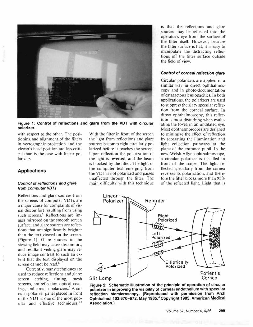
Figure 1: Control of reflections and glare from the vor with circular polarizer.
with respect to the other. The positioning and alignment of the filters in vectographic projection and the viewer's head position are less critical than is the case with linear polarizers.
Applications
Control of reflections and glare from computer VDTs
Reflections and glare sources from the screens of computer VDTs are a major cause for complaints of visual discomfort resulting from using such screens. 5 Reflections are i mages mirrored on the smooth screen surface, and glare sources are reflections that are significantly brighter than the text viewed on the screen. (Figure 1). Glare sources in the viewing field may cause discomfort, and resultant veiling glare may reduce image contrast to such an extent that the text displayed on the screen cannot be read. 6
Currently, many techniques are used to reduce reflections and glare: screen etching, tIntIng, mesh screens, antireflection optical coatings, and circular polarizers.7 A circular polarizer panel placed in front of the VDT is one of the most pop
sular and effective techniques. 5.
With the filter in front of the screen the light from reflections and glare sources becomes right circularly polarized before it reaches the screen . Upon reflection the polarization of the light is reversed , and the beam is blocked by the filter. The light of the computer text emerging from the VDT is not polarized and passes unaffected through the filter. The main difficulty with this technique
Slit Lamp
is that the reflections and glare sources may be reflected into the operator's eye from the surface of the filter itself. However, because the filter surface is flat, it is easy to manipulate the distracting reflections off the filter surface outside the field of view.
Control of corneal reflection glare
Circular polarizers are applied in a similar way in direct ophthalmoscopy and in photo-documentation ofcataractous lens opacities. In both applications, the polarizers are used to suppress the glary specular reflection from the corneal surface. In direct ophthal moscopy, this reflection is most disturbing when evaluating the fovea in an undilated eye. Most ophthalmoscopes are designed to minimize the effect of reflection by separating the illumination and light collection pathways at the plane of the entrance pupil. In the new Welsh-Allyn ophthalmoscope, a circular polarizer is installed in front of the scope. The light reflected specularly from the cornea reverses its polarization, and therefore the filter blocks more than 95 % of the reflected light. Light that is
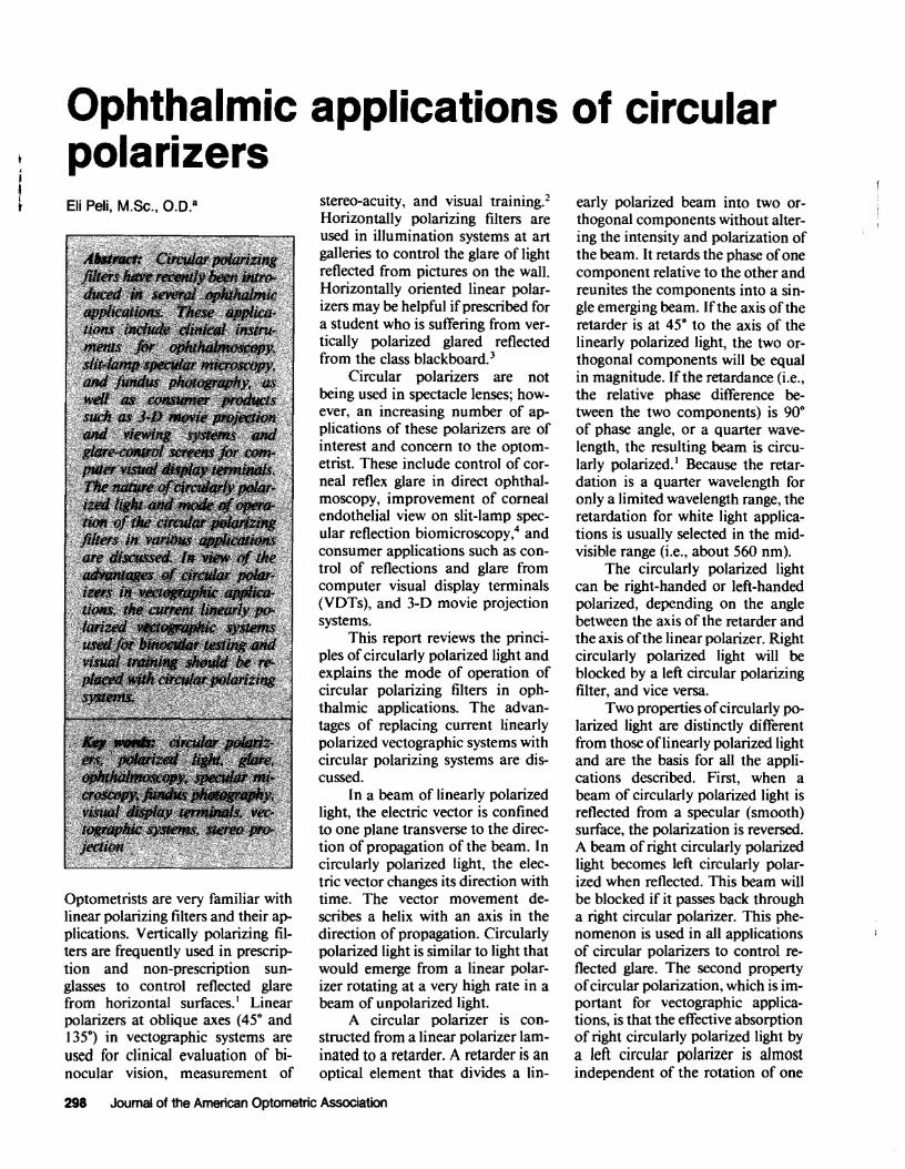
Elliptically Polarized
Patient's Cornea
Figure 2: Schematic illustration of the principle of operation of circular polarizer in improving the visibility of corneal endothelium with specular reflection biomicroscopy. (Reproduced with permisSion from Arch OphthalmoI103:670-672, May 1985.4 Copyright 1985, American Medical Association. )
Volume 57, Number 4,4/86 299
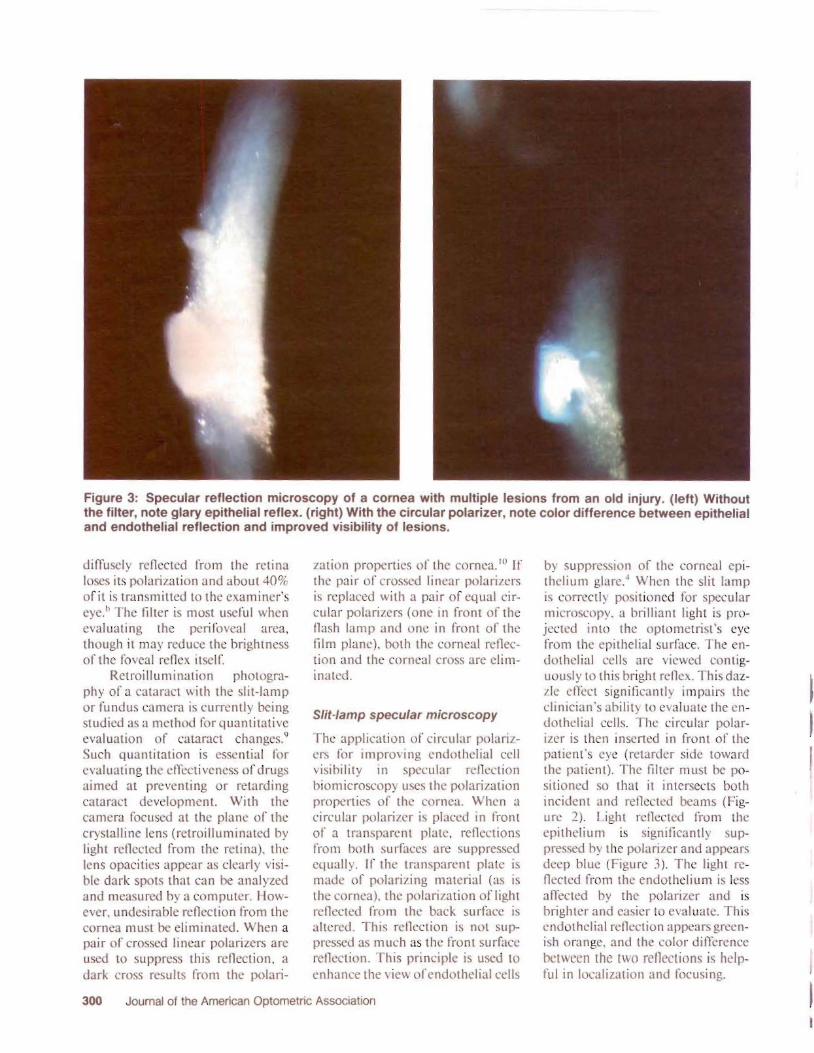
Figure 3: Specular reflection microscopy of a cornea with multiple lesions from an old injury. (left) Without the filter, note glary epithelial reflex. (right) With the circular polarizer, note color difference between epithelial and endothelial reflection and improved visibility of lesions.
dilTuscly reflected from the retina loses its polarization and about 40% of it is tra nsmitted to the examiner's eye. 11 The filter is most useful when evaluating the periloveal area , though it may reduce the brightness of the foveal rctlex itself
Retroillumination photography of a cataract with the slit -lamp or fundus camera is currenLly being studied as a method for quant itative evaluation of cataract changes. 9
Such quantitation is essential for evaluati ng the efTccti veness of drugs aimed at preventing or retarding cataract development. With the camera focused at the plane of the crystalline lens (retroilluminated by light reflected from the retina), the lens opacities appear as clearly visible dark spots that can be analyzed and measured by a computer. Ilowever. undesirable reflection from the cornea must be eliminated . When a pair I' ero sed linear polarizers are used to suppress this reflection , a dark cross results from the polari
zation properties of the cornea. III If the pair of crossed linear polarizers is replaced with a pair of equal circular polari/crs (one in front of the flash lamp and one in front of the film plane). hoth the corneal rellection and the corneal cross are eliminated .
Slit-lamp specular microscopy
The application of circular polarilcrs fc r improving C'ndothclial cell visibility In specular rellection biomicroscopy uses the polari/_ation properties of tht.: cornea. When a circular polarizer i placed in front of a tran parent plate, reflections from hoth surfacts are suppressed equally. If the transparent plate is made of polarizing material (as is the cornea), the polarization of light reflected from the baek surface is altered. This reflection is n t suppressed as much as the front surface reflection. This princirle is used to cnham:e [he view ofendothelial cells
300 Joumal of the American Optometric Association
by suppression of the corneal epithelium glare:' When the slit lamp is correc tly posit ioned for specular microscorY. a brilliant light is projected into the optometrist's eye from the epithelial surface. The endothelial cells arc viewed contiguously to this br ight reflex . Th i dazIll' effect significantly impai rs the clinician's ability to evaluate the I.!n dothelial cells . The circular polarizer is then insert d in front of the patient's eye (retarder side toward the patient) . The filter must be positioned so that it intersects both incident and reflected beams (Figure 2) Light reflected from the epithelium is significantly . uppressed by the polarizer and appears deep blue (Figure 3). The light reflec ted froOl the endothel ium i less afTected hy the polarizer and is brighter and easier to eval uate . This endothelial reflection appears greenish orange. and the color difTerence between the two reflections i helpful in localiz.ation and focusing.
T V H P Rue F N C
T V H P Rue F N C
N R T S F ,"
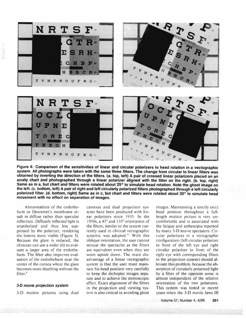
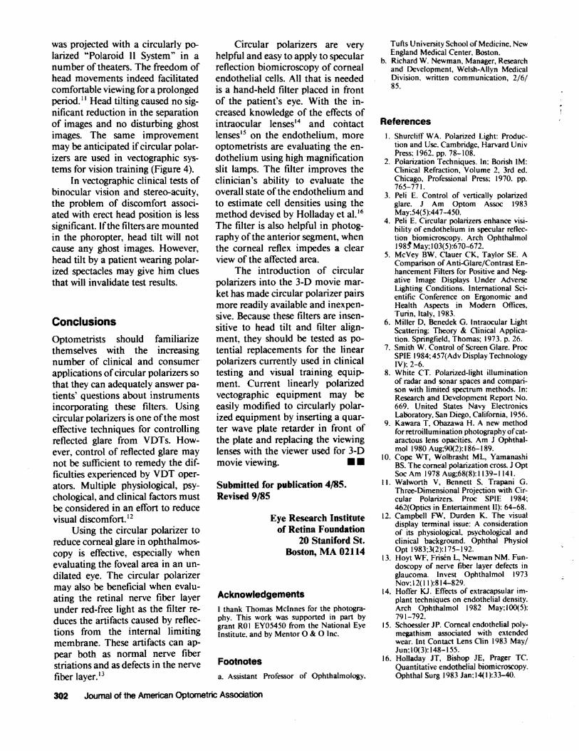
Figure 4: Comparison of the sensitivi,ties of linear and circular polarizers to head rotation in a vectographic system. All photographs were taken with the same three filters. The change from circular to linear filters was obtained by inverting the direction of the filters. (a. top, left) A pair of crossed linear polarizers placed on an acuity chart and photographed through a linear polarizer aligned with the filter on the right. (b. top, right) Same as in a, but chart and filters were rotated about 25° to simulate head rotation. Note the ghost image on the left. (c. bottom, left) A pair of right and left circularly polarized filters photographed through a left Circularly polarized filter. (d. bottom, right) Same as in c, but chart and filters were rotated about 30° to simulate head movement with no effect on separation of images.
Abnormalities of the endotheliurn or Descemet's membrane result in diffuse rather than specular retlection . Diffusely retlected light is unpolarized and thus less suppressed by the polarizer, rendering the lesions more visible (Figure 3). Because the glare is reduced , the clinician can use a wider slit to evaluate a larger area of the endothelium. The filter also improves evaluation of the endothelium near the center of the cornea where the glare becomes more disabling without the fit ter. 4
3-~ movie projection system
3-D motion pictures using dual
cameras and dual projection systems have been produced with linear polarizers since 1935. In the J950s, a 45" and 135 0 orientation of the filters, similar to the system currently used in clinical vectographic systems, was adopted. I I With this oblique orientation, the user cannot misuse the spectacles as the filters are equivalent even when they are worn upside down. The main disadvantage of a linear vectographic system is that the user must maintain his head position very carefully to keep the dichoptic images separate and to achieve the stereoscopic effect. Exact alignment of the filters in the projection and viewing system is also critical in avoiding ghost
images. Maintaining a strictly erect head position throughout a fulllength motion picture is very uncomfortable and is associated with the fatigue and asthenopia reported by many 3-D movie spectators. Circular polarizers in a vectographic configuration (left circular polarizer in front of the left eye and right circular polarizer in front of the right eye with corresponding filters in the projection system) should alleviate this problem, because the absorption of circularly polarized light by a filter of the opposite sense is almost independent of the relative orientation of the two polarizers. This system was tested in recent years when the 3-D movie Jaws III
Volume 57. Number 4. 4/86 301
was projected with a circularly polarized "Polaroid II System" in a number of theaters. The freedom of head movements indeed facilitated comfortable viewing for a prolonged period. II Head tilting caused no significant reduction in the separation of images and no disturbing ghost images. The same improvement may be anticipated if circular polarizers are used in vectographic systems for vision training (Figure 4).
In vectographic clinical tests of binocular vision and stereo-acuity, the problem of discomfort associated with erect head position is less significant. Ifthe filters are mounted in the phoropter, head tilt will not cause any ghost images. However, head tilt by a patient wearing polarized spectacles may give him clues that will invalidate test results.
Conclusions
Optometrists should familiarize themselves with the increasing number of clinical and consumer applications ofcircular polarizers so that they can adequately answer patients' questions about instruments incorporating these filters. Using circular polarizers is one ofthe most effective techniques for controlling reflected glare from VOTs. However, control of reflected glare may not be sufficient to remedy the difficulties experienced by VOT operators. Multiple physiological, psychological, and clinical factors must be considered in an effort to reduce visual discomfort. 12
Using the circular polarizer to reduce corneal glare in ophthalmoscopy is effective, especially when evaluating the foveal area in an undilated eye. The circular polarizer may also be beneficial when evaluating the retinal nerve fiber layer under red-free light as the filter reduces the artifacts caused by reflections from the internal limiting membrane. These artifacts can appear both as normal nerve fiber striations and as defects in the nerve fiber layer. 13
Circular polarizers are very helpful and easy to apply to specular reflection biomicroscopy of corneal endothelial cells. All that is needed is a hand-held filter placed in front of the patient's eye. With the increased knowledge of the effects of intraocular lensesl4 and contact lenses15 on the endothelium, more optometrists are evaluating the endothelium using high magnification slit lamps. The filter improves the clinician's ability to evaluate the overall state of the endothelium and to estimate cell densities using the method devised by Holladay et al. 16
The filter is also helpful in photography ofthe anterior segment, when the corneal reflex impedes a clear view of the affected area.
The introduction of circular polarizers into the 3-0 movie market has made circular polarizer pairs more readily available and inexpensive. Because these filters are insensitive to head tilt and filter alignment, they should be tested as potential replacements for the linear polarizers currently used in clinical testing and visual training equipment. Current linearly polarized vectographic equipment may be easily modified to circularly polarized equipment by inserting a quarter wave plate retarder in front of the plate and replacing the viewing lenses with the viewer used for 3-0 movie viewing. • •
Submitted for publication 4/85. Revised 9/85
Eye Research Institute of Retina Foundation
20 Staniford St. Boston, MA 02114
Acknowledgements I thank Thomas McInnes for the photography. This work was supported in part by grant ROI EY05450 from the National Eye Institute. and by Mentor 0 & 0 Inc.
Footnotes
a. Assistant Professor of Ophthalmology,
302 Journal of the American Optometric Association
Tufts University School of Medicine, New England Medical Center, Boston.
b. Richard W. Newman, Manager, Research and Development, Welsh-Allyn Medical Division, written communication, 2/6/ 85.
References
I. Shurclilf W A. Polarized Light: Production and Use. Cambridge, Harvard Univ Press; 1962. pp. 78-108.
2. Polarization Techniques. In: Borish 1M: Clinical Refraction, Volume 2, 3rd ed. Chicago, Professional Press; 1970. pp. 765-771.
3. Peli E. Control of vertically polarized glare. J Am Optom Assoc 1983 May;54(5):447-450.
4. Peli E. Circular polaiizers enhance visibility of endothelium in specular reflection biomicroscopy. Arch Ophthalmol 1985" May; I 03( 5 ):670-612.
5. McVey BW, Clauer CK, Taylor SE. A Comparison of Anti-Glare/Contrast Enhancement Filters for Positive and Negative Image Displays Under Adverse Lighting Conditions. International Scientific Conference on Ergonomic and Health Aspects in Modern Offices, Turin, Italy, 1983.
6. Miller D, Benedek G. Intraocular Light Scattering: Theory & Clinical Application. Springfield, Thomas; 1973. p. 26.
7. Smith W. Control of Screen Glare. Proc SPIE 1984; 457(Adv Display Technology IV); 2-6.
8. White CT. Polarized-light illumination of radar and sonar spaces and comparison with limited spectrum methods. In: Research and Development Report No. 669. United States Navy Electronics Laboratory, San Diego, California, 1956.
9. Kawara T. Obazawa H. A new method for retroillumination photography ofcataractous lens opacities. Am J Ophthalmol 1980 Aug;90(2):186-189.
10. Cope WT, Wolbrasht ML, Yamanashi BS. The corneal polarization cross. J Opt Soc Am 1978 Aug;68(8):1139-1141.
II. Walworth V, Bennett S, Trapani G. Three-Dimensional Projection with Circular Polarizers. Proc SPIE 1984; 462(Optics in Entertainment II): 64-68.
12. Campbell FW, Durden K. The visual display terminal issue: A consideration of its physiological, psychological and clinical background. Ophthal Physiol Opt 1983;3(2):175-192.
13. Hoyt WF, Frisen L, Newman NM. Fundoscopy of nerve fiber layer defects in glaucoma. Invest Ophthalmol 1973 Nov: I 2(1 1):814-829.
14. Hoffer KJ. Effects of extracapsular implant techniques on endothelial density. Arch Ophthalmol 1982 May;tOO(5): 791-792.
15. Schoessler JP. Corneal endothelial polymegathism associated with extended wear. Int Contact Lens Clin 1983 May/ Jun;10(3): 148-155.
16. Holladay JT, Bishop JE, Prager TC. Quantitative endothelial biomicroscopy. Ophthal Surg 1983 Jan:I4(J):33-40.