OPERATIONAL EXPENDITURE COST ANALYSIS FOR SMALL …...dibekalkan kepada penyongsang arus DC/AC. Arus...
95
OPERATIONAL EXPENDITURE COST ANALYSIS FOR SMALL SCALE PROTON EXCHANGE MEMBRANE FUEL CELL AIDA BINTI DEN UNIVERSITI TEKNOLOGI MALAYSIA
Transcript of OPERATIONAL EXPENDITURE COST ANALYSIS FOR SMALL …...dibekalkan kepada penyongsang arus DC/AC. Arus...
OPERATIONAL EXPENDITURE COST ANALYSIS FOR SMALL SCALE
PROTON EXCHANGE MEMBRANE FUEL CELL
AIDA BINTI DEN
UNIVERSITI TEKNOLOGI MALAYSIA


NOTES : If the thesis is CONFIDENTIAL or RESTRICTED, please attach with the letter from
the organization with period and reasons for confidentiality or restriction
PSZ 19:16 (Pind. 1/13)
UNIVERSITI TEKNOLOGI MALAYSIA
DECLARATION OF THESIS / UNDERGRADUATE PROJECT REPORT AND
COPYRIGHT Author’s full name : AIDA BINTI DEN
Date of Birth : 24 OCTOBER 1989
Title : OPERATIONAL EXPENDITURE COST ANALYSIS FOR SMALL
SCALE PROTON EXCHANGE MEMBRANE FUEL CELL
Academic Session : 2018/2019
I declare that this thesis is classified as:
CONFIDENTIAL (Contains confidential information under the
Official Secret Act 1972)*
RESTRICTED (Contains restricted information as specified by the
organization where research was done)*
OPEN ACCESS I agree that my thesis to be published as online
open access (full text)
1. I acknowledged that Universiti Teknologi Malaysia reserves the right as
follows:
2. The thesis is the property of Universiti Teknologi Malaysia
3. The Library of Universiti Teknologi Malaysia has the right to make copies for
the purpose of research only.
4. The Library has the right to make copies of the thesis for academic
exchange.
Certified by:
SIGNATURE OF STUDENT SIGNATURE OF SUPERVISOR
MJ133044 DR. RASLI BIN ABD GHANI
MATRIC NUMBER NAME OF SUPERVISOR
Date: 7 MARCH 2019 Date: 7 MARCH 2019


“I hereby declare that I have read this thesis and in my
opinion this thesis is sufficient in term of scope and quality for the
award of the degree of Master of Philosophy”
Signature : ______________________
Name of Supervisor I : RASLI BIN ABD GHANI
Date : 7 MARCH 2019


BAHAGIAN A – Pengesahan Kerjasama*
Adalah disahkan bahawa projek penyelidikan tesis ini telah dilaksanakan melalui kerjasama
antara _______________________ dengan _______________________
Disahkan oleh:
Tandatangan : Tarikh :
Nama :
Jawatan : (Cop rasmi)
* Jika penyediaan tesis/projek melibatkan kerjasama.
BAHAGIAN B – Untuk Kegunaan Pejabat Sekolah Pengaji an Siswazah
Tesis ini telah diperiksa dan diakui oleh: Nama dan Alamat Pemeriksa Luar : Assoc. Prof. Dr. Ahmad Maliki bin Omar
Fakulti Kejuruteraan Elektrik, Universiti
Teknologi Mara, 40450, Shah Alam, Selangor
Nama dan Alamat Pemeriksa Dalam : Dr. Mohd Nabil bin Muhtazaruddin
Razak Faculty of Technology and Informatics,
UTM Kuala Lumpur
Nama Penyelia lain (jika ada) :
Disahkan oleh Timbalan Pendaftar di Malaysia-Japan International Institute of Technology (MJIIT) :
Tandatangan : Tarikh : Nama :


OPERATIONAL EXPENDITURE COST ANALYSIS FOR SMALL SCALE
PROTON EXCHANGE MEMBRANE FUEL CELL
AIDA BINTI DEN
A thesis submitted in fulfilment of the
requirements for the award of the degree of
Master of Philosophy
Malaysia-Japan International Institute of Technology
Universiti Teknologi Malaysia
MARCH 2019

ii
DECLARATION
I declare that this thesis entitled “Operational Expenditure Cost Analysis for Small
Scale Proton Exchange Membrane Fuel Cell” is the result of my own research
except as cited in the references. The thesis has not been accepted for any degree and
is not concurrently submitted in candidature of any other degree.
Signature : ................................
Name : AIDA BINTI DEN
Date : 7 MARCH 2019

iii
DEDICATION
To all people around me who are very supportive.

iv
ACKNOWLEDGEMENT
Praise to Almighty that I managed to finish this long journey. Without believe
that whatever happened in this world is according to His best decision, I think
I cannot reach this far. May Allah s.w.t accept all my effort to go through this
journey. To my supervisor, who is very supportive and always believe in me,
Dr Rasli bin Abd Ghani, thank you very much for your support for this five years.
I hope I still get the chance to work with you in the future.
To all Ocean Thermal Energy Conversion (OTEC) Centre members,
especially Dato’ Abu Bakar Jaafar and Prof Md Nor bin Musa, thank you for giving
me a chance to join OTEC Centre. Hopefully our vision to build OTEC Tower will
become reality in the near future. To MJIIT especially Advanced Devices and
Material Engineering Lab’s members thank you for your support. To my family,
especially my parents and my husband, Hadi thank you for your understanding that
I am not only one of the family members of you but also citizen that is trying to
upgrade herself in order to contribute to her nation. Last but not least, to all who had
been directly and in directly related to this research and help me.
Thank you very much.

v
ABSTRACT
Rural areas in Sabah have problems connecting to the national grid due to
their geographical conditions. Hence, the Proton Exchange Membrane Fuel Cell
(PEMFC) off-grid power system using hydrogen from the Ocean Thermal Energy
Conversion (OTEC) is recommended. This study carried out calculations for the
operational cost using hydrogen from OTEC to serve as baseline for the
implementation of PEMFC off-grid power system. Performance of small scale off-
grid power system using hydrogen has been analysed and proposed to overcome this
problem. To demonstrate the off-grid system, 1 kW PEMFC from the
Horizon Fuel Cell Company model H-1000XP was used. Direct Current (DC) output
from PEMFC was regulated using DC/DC converter prior supply to the DC/AC
inverter. DC voltage was inverted to Alternate Current (AC) by using 1 kW
pure sine wave inverter from Swipower Company and supplied to the customized
1 kW of bulb loads. This system shows that PEMFC was able to deliver power of
up to 400 W and the efficiency was 40%. The operational cost for 1 kW PEMFC
using hydrogen from OTEC for 25 years was calculated as RM316,066,410.
Data of the existing diesel generator capacity in Felda Sahabat, Sabah was used as a
guideline to propose the PEMFC capacity for Felda Sahabat. The total diesel
generator capacity in Felda Sahabat was 10,785 kW. Estimation for suitable
electrical power plant capacity for Felda Sahabat was 80% from the total
diesel generator capacity which was recorded as 8,628 kW. In order to obtain net
power of 8,628 kW, the idea was to develop PEMFC in modular mode whereas each
modular power rated was 100 kW. Electrical specification for 100 kW was between
1.2 kV to 1.44 kV for voltage and 0 A to 70 A for current, respectively. A total of
216 units of 100 kW modular PEMFC were required to deliver net power of
8,628 kW using 40% efficiency of PEMFC off-grid power system estimation.

vi
ABSTRAK
Kawasan pedalaman di Sabah mempunyai masalah untuk dihubungkan
dengan grid nasional kerana keadaan geografinya. Justeru, penjana eletrik Sel Bahan
Api Membran Pertukaran Proton (PEMFC) yang tidak bersambung kepada grid dan
menggunakan hidrogen dari Sistem Penukaran Tenaga Haba Lautan (OTEC) adalah
disyorkan. Kajian ini menjalankan pengiraan kos operasi sistem PEMFC dengan
menggunakan sumber hidrogen dari OTEC untuk menjadi asas bagi perlaksanaan
sistem PEMFC. Janakuasa elektrik pada skala kecil bagi sistem yang tidak
bersambung kepada grid yang menggunakan hidrogen telah dianalisa dan
dicadangkan untuk mengatasi masalah ini. Untuk pengujian sistem ini, 1 kW PEMFC
model H-1000XP dari Syarikat Horizon Fuel Cell telah digunakan. Arus terus (DC)
dari PEMFC dikawal dengan menggunakan penukar arus DC/DC sebelum
dibekalkan kepada penyongsang arus DC/AC. Arus terus (DC) ditukarkan kepada
arus ulang alik (AC) menggunakan penyongsang arus dari Syarikat Swipower dan
dihantar kepada beban lampu sebanyak 1 kW. Sistem ini menunjukkan bahawa
PEMFC mampu membekalkan elektrik sehingga 400 W dan kecekapannya adalah
40%. Kos perbelanjaan operasi untuk 1 kW PEMFC menggunakan sumber hidrogen
dari OTEC selama 25 tahun telah dikira dan hasilnya adalah RM316,066,410.
Data mengenai kapasiti penjana diesel sedia ada di Felda Sahabat, Sabah telah
dikumpulkan sebagai garis panduan untuk mencadangkan kapasiti PEMFC bagi
Felda Sahabat. Kapasiti penjana diesel di Felda Sahabat adalah 10,785 kW.
Anggaran kapasiti loji kuasa elektrik yang sesuai untuk Felda Sahabat adalah 80%
dari jumlah kapasiti penjana diesel iaitu 8,628 kW. Untuk mendapatkan kuasa bersih
8,628 kW, PEMFC dibangunkan dalam bentuk modular dan nilai kuasa elektrik
setiap modular adalah 100 kW. Spesifikasi elektrik untuk 100 kW adalah di antara
1.2 kV hingga 1.44 kV untuk voltan dan 0 A hingga 70 A untuk arus. 261 unit
100 kW modular PEMFC dikehendaki untuk mendapatkan kuasa bersih 8,628 kW
berdasarkan kecekapan sistem PEMFC 40%.

vii
TABLE OF CONTENTS
TITLE PAGE
DECLARATION ii
DEDICATION iii
ACKNOWLEDGEMENT iv
ABSTRACT v
ABSTRAK vi
TABLE OF CONTENTS vii
LIST OF TABLES ix
LIST OF FIGURES x
LIST OF ABBREVIATIONS xii
LIST OF SYMBOLS xiv
LIST OF APPENDICES xv
CHAPTER 1 INTRODUCTION 1
1.1 Background 1
1.2 Problem Statement 2
1.3 Objectives of Research 4
1.4 Scope 5
1.5 Thesis Organization 5
CHAPTER 2 LITERATURE REVIEW 7
2.1 Sabah Power Generation 7
2.1.1 Photovoltaic in Sabah 11
2.1.2 Biogas and Biomass in Sabah 13
2.1.3 Small Hydro in Sabah 15
2.1.4 Geothermal in Sabah 15
2.1.5 Ocean Thermal Energy Conversion in Sabah 16
2.2 Proton Exchange Membrane Fuel Cell (PEMFC) 19
2.3 Overview of Hydrogen 25

viii
CHAPTER 3 RESEARCH METHODOLOGY 29
3.1 Experiment Set up for Small Scale Off-grid Power
System 29
3.2 Data Collection of Felda Sahabat 36
CHAPTER 4 RESULTS AND DISCUSSION 41
4.1 Experimental Result of Small Scale Off-grid Power
System 41
4.2 OPEX for Small Scale PEMFC 45
4.3 Estimate Specification of 100 kW PEMFC 47
CHAPTER 5 CONCLUSION AND RECOMMENDATIONS 53
5.1 Conclusion 53
5.2 Recommendation 54
REFERENCES 55

ix
LIST OF TABLES
TABLE NO. TITLE PAGE
Table 2.1 Installed capacity of power generation in Sabah as of 31st
December 2015 [2] 10
Table 2.2 List FiAH biogas power plant in Sabah [28] 14
Table 2.3 List FiAH biomass power plant in Sabah [28] 14
Table 2.4 List FiAH hydro power plant in Sabah [28] 15
Table 2.5 Fuel cell types [53] 22
Table 2.6 Cost of hydrogen based on OTEC size [44] 28
Table 3.1 Specification of 1 kW PEMFC [61] 31
Table 3.2 List of available diesel generator in Felda Sahabat [64] 38
Table 4.1 Ambient temperature, stack temperature, battery voltage,
stack current, stack voltage and stack power at different
load power 45
Table 4.2 Lifetimes assumption for system components 45
Table 4.3 Specification of 5 kW PEMFC 48
Table 4.4 Estimation specification for 100 kW PEMFC 51

x
LIST OF FIGURES
FIGURE NO. TITLE PAGE
Figure 2.1 SAIDI of Sabah, Sarawak and Peninsular Malaysia 8
Figure 2.2 Hybrid PV-PEMFC system diagram [26] 13
Figure 2.3 OTEC power plant concept taken from [40] 17
Figure 2.4 OTECpower plant concept with electrolyzer and hydrogen
storage [40] 18
Figure 2.5 PEMFC concept [46] 19
Figure 2.6 Membrane Electrode Assembly (MEA) [48] 20
Figure 2.7 Small scale off-grid power system using PEMFC as power
generator; (a) with reformer (b) without reformer 24
Figure 2.8 DEMCOPEM-2 PEMFC power plant at Ynnovate,
Yingkou [58] 25
Figure 2.9 Steam reformer [59] 26
Figure 2.10 Standard electrolysis [60] 27
Figure 3.1 Experimental set up for PEMFC off-grid power system 30
Figure 3.2 Polarization curve for H-1000XP [61] 32
Figure 3.3 Hydrogen consumption rate at different output power [61] 32
Figure 3.4 Alternate Current (AC) load 33
Figure 3.5 Electrical circuit diagram for H-1000XP [61] 34
Figure 3.6 Electrical circuit diagram for H-1000XP with external
DC/DC converter and DC/AC inverter [61] 35
Figure 3.7 Location of Felda Sahabat [63] 37
Figure 4.1 Stack power, stack current and stack voltage at 0 W 42
Figure 4.2 Stack power, stack current and stack voltage at 100 W 42
Figure 4.3 Stack power, stack current and stack voltage at 200 W 43
Figure 4.4 Stack power, stack current and stack voltage at 300 W 43
Figure 4.5 Stack power, stack current and stack voltage at 400 W 44
Figure 4.6 Stack power, stack current and stack voltage at 500 W 44

xi
Figure 4.7 Modular system for 21, 570 kW PEMFC 49

xii
LIST OF ABBREVIATIONS
AC - Alternate Current
AFC - Alkaline Fuel Cell
BELB - Bekalan Elektrik Luar Bandar
CAPEX - Capital Expenditure
CERs - Carbon Emission Credits
DC - Direct Current
DMFC - Direct Methanol Fuel Cell
ECG - East Coast Grid
EFB - Empty Fruit Bunch
FiAH - Feed in Approval Holder
FiT - Feed in Tariff
IPPs - Independent Power Producer
KeTTHA - Ministry of Energy, Green Technology and Water
MEA - Membrane Electrode Assembly
MESTECC - Ministry of Energy, Science, Technology, Environment and
Climate Change
MFC - Molten Carbonate Fuel Cell
MFO - Marine Fuel Oil
MOSTI - Ministry of Science, Technology and Innovation
NRE - Ministry of Natural Resources and Environment
O&M - Operation and Maintenance
OPEX - Operational Expenditure
OTEC - Ocean Thermal Energy Conversion
PAFC - Phosphoric Acid Fuel Cell
PEMANDU - Pemandu Associates Sdn Bhd
PEMFC - Proton Exchange Membrane Fuel Cell
PETRONAS - Petroliam Nasional Berhad
PV - Photovoltaic
RE - Renewable Energy
SAIDI - System Average Interruption Duration Index

xiii
SEDA - Sustainable Energy Development Authority in Malaysia
SESB - Sabah Electricity Sdn Bhd
SJAT - Stesen Janakuasa Anjung Tanah
SJBA - Stesen Janakuasa Baiduri Ayu
SJBS/DK - Stesen Janakuasa Bandar Sahabat or Desa Kencana
SJC - Stesen Janakuasa Cenderawasih
SJEB - Stesen Janakuasa Embara Budi
SJFH - Stesen Janakuasa Fajar Harapan
SJGP - Stesen Janakuasa Gemala Pura
SJHB - Stesen Janakuasa Hamparan Badai
SJJB - Stesen Janakuasa Jeragan Bestari
SJKS - Stesen Janakuasa Kembara Sakti
SLPM - Standard Liter Per Minute
SMR - Steam Methane Reforming
SOFC - Solid Oxide Fuel Cell
WCG - West Coast Grid

xiv
LIST OF SYMBOLS
A - Ampere
atm - Atmosphere
°C - Degree Celsius
kg - Kilogram
kW - Kilowatt
kV - Kilo volt
L - Liter
MW - Megawatt
MWh - Megawatt Hour
W - Watt

xv
LIST OF APPENDICES
APPENDIX TITLE PAGE
Appendix A Website Photovoltaic Monitoring System by SEDA
Malaysia 63
Appendix B Major Power Station and Grid Supply in Sabah 64
Appendix C PEMFC Catalogue from Horizon Fuel Cell 65
Appendix D Specification of Inverter 69
Appendix E Ambient Temperature Sensor 70
Appendix F PEMFC H-1000XP Controller 71


1
CHAPTER 1
INTRODUCTION
1.1 Background
Sabah has large rural area and difficult to connect with national grid in terms
of physical geography because distance from nearest national grid are more than
20 km. Long transmission lines increase power distribution losses and power
transmission losses. According to The Borneo Post on 24th
October 2018,
Yeo Bee Yin, Minister of Ministry of Energy, Science, Technology, Environment
and Climate Change (MESTECC), Sabah’s electricity problem is not only about
generation, interruptions in Sabah are caused by transmission and distribution
problems [1]. Hence, standalone power generator is good option to overcome this
problem. Installed capacity of power generators in Sabah as of 31st December 2015
are hydro (82.5 MW), natural gas (1231.4 MW), diesel/Marine Fuel Oil (MFO)
(897.6 MW), biomass (301.5 MW), photovoltaic (PV) (18.3 MW) and
biogas (6.1 MW) [2].
Natural gas power plant is the largest power generator available in Sabah.
Instead of hydro, biomass, PV and biogas, OTEC is one of the potential renewable
energy available in Sabah. Sabah has potential to develop OTEC in the
Sabah Trough up to 50,000 MW [3][4]. Electricity from OTEC can be utilised to
produce hydrogen instead of directly delivery the energy to Sabah rural area due to
long transmission line. Hydrogen from OTEC is useful for PEMFC to generate
electricity. PEMFC can convert chemical energy of hydrogen into electrical energy.

2
1.2 Problem Statement
Electricity distribution system performance in Sabah is inadequate compare
to Peninsular Malaysia and Sarawak. Report entitle “Malaysia Energy Statistic
Handbook 2017” published by Energy Commission shows in 2016, unscheduled
interruption per 1,000 customers in Sabah is the highest which is 32.15 compare to
Peninsular Malaysia and Sarawak which are 6.68 and 6.98, respectively [2].
System Average Interruption Duration Index (SAIDI) for Sabah also is the highest
compare to Peninsular Malaysia and Sarawak. Poor electricity distributions interrupt
daily activity of people in Sabah. Sabah Electricity Sdn Bhd (SESB) share news from
Daily Express on SESB website entitle “Lahad Datu folks want electricity supply
reconnected”. The news mention one of the villagers from Batu 1, Jalan Segama
Lahad Datu, Sabah urges government to expedite reinstallation of electrical
substation for supplying electricity to his village [5]. The villager also said that
inoperative electrical substation that being built before should be reactivated to
supply electricity to villagers.
According to the villager, they generate their own electricity for their usage
because electricity supplied by SESB is not stable. Their monthly expenses increase
because they have to buy diesel to operate their own diesel generator. Borneo Today
reported the article “Sabah SAIDI 100 lab to find permanent solutions to electricity
problem”[6]. This article is about special task force called Sabah SAIDI 100 Lab is
launched in Sabah. It is joint programme between Ministry of Energy,
Green Technology and Water (KeTTHA) and Pemandu Associates Sdn Bhd
(PEMANDU) to improve power distribution quality in Sabah. Dr. Maximus Ongkili,
previous Minister of KeTTHA inform that RM3.21 billion are allocated to the SESB
since 2001 to enhance the state’s electricity supply infrastructure developments,
besides channelled RM7.1 billion to subsidise fuel for power distribution since
2004 to 2017[6].

3
After the 14th
Malaysian general election was held on 9th
May 2018, the entire
component of Ministry of Science, Technology and Innovation (MOSTI), KeTTHA
and related component of Climate Change and Environment from
Ministry of Natural Resources and Environment (NRE) had been restructured and
formed MESTECC. Federal Government under MESTECC and Sabah Government
cooperate to solve the SAIDI problem in Sabah. Efforts from both government show
positive result when SAIDI in Sabah reduce from 1856 in 2008 to 241 in 2017 [7][8].
Eventhough SAIDI rate in Sabah reduce, there are 603 villages with
19,761 houses are not receive electricity and 207 houses from 19,761 houses are
listed in Rural Electricity Supply Project or Bekalan Elektrik Luar Bandar (BELB)
which is under progress [9]. Under BELB, PV hybrid systems are installed to supply
electricity in remote area. Installation of PV/diesel mini grid based on guideline
70% PV/battery to 30% diesel or 50% PV/battery to 50% diesel, depending on
source available on the site [10].
PV/diesel installation in Sabah is reliable to supply electricity if battery
systems have sufficient capacity [11]. If not, fuel consumption for diesel generator
increase cause more money to buy diesel [11]. Lead acid battery is the common
battery for energy backup in PV power supply system. Typical life time for the
battery is 500 to 1200 cycles or numbers of charging and discharging [12]. Others
report life time of lead acid battery is 5 to 15 years depend on usage [13]. Short life
time of battery is one of the issues that increase cost of operating PV. Instead of
battery, PEMFC has potential to combine with PV for energy storage.
From aforementioned statement in background, Sabah has potential to
produce hydrogen using OTEC. Felda Sahabat, Sabah is suitable area for pilot
project to commercialize hydrogen from OTEC for electricity generation due to easy
transportation from OTEC power plant to resident area. Data collection from
Felda Engineering Sdn Bhd and through literature search show diesel generator and
biomass power plant are existing electricity power plant available in
Felda Sahabat [14]. The power plant are equipped with 5 x 1 MW diesel generators
as backup throughout breakdowns similarly provide power during boiler inspection

4
in biomass power plant. It’s anticipated that biomass plant use diesel generator for
two weeks each year during annual Operation and Maintenance (O&M) of the
Empty Fruit Bunch (EFB) facility. PEMFC can replace diesel generator as a backup
during O&M as an alternative for clean electricity generation.
PEMFC has flexibility to use as standalone power plant or integrate with
other electricity generation such as biomass and PV for energy storage and backup.
However, in Malaysia, not much study about cost implementation of PEMFC as
off-grid power system to generate electricity. Cost of implementation involves
Capital Expenditure (CAPEX) and Operational Expenditure (OPEX). This thesis will
discuss of OPEX cost analysis for small scale PEMFC as a baseline for
implementation of this system in the future. Main cost for OPEX cost for PEMFC is
fuel which is hydrogen to operate the PEMFC. In this thesis, calculation for
hydrogen cost based on cost of hydrogen production from OTEC can be guideline for
power plant developer in Malaysia to develop power plant using hydrogen supply
from OTEC. OTEC is new technology in Malaysia which has potential to produce
hydrogen in large scale to meet demand for hydrogen in Malaysia.
1.3 Objectives of Research
The objectives of the research are :
(a) To develop a small scale of off-grid power system using PEMFC as a main
power generator for studying the system efficiency.
(b) To calculate OPEX for small scale PEMFC.
(c) To estimate electrical specification for bigger size PEMFC as proposal for
Felda Sahabat, Sabah

5
1.4 Scope
For objective to develop a small scale of off-grid power system using
PEMFC as a main power generator for studying the system efficiency, components
of small scale of off-grid power system using PEMFC as main power source will be
studied based on literature. Components of hydrogen supply and power conditioning
which are DC/DC converter and DC/AC inverter that suitable with small scale
PEMFC is being search based on literature. Then, all the components will be
integrated and analysis of efficiency for 1 kW small scale PEMFC off-grid power
system will be evaluated using Alternate Current (AC) load.
To calculate OPEX for small scale PEMFC, measurement of hydrogen
consumption not included in the experiment. Hydrogen consumption data for
operational cost analysis adopted directly from H-1000XP user manual (data sheet).
After that, operational expenditure cost of PEMFC will be calculated based on
hydrogen consumption rate and price of hydrogen from OTEC. In addition, data of
existing electrical generation type and capacity in case study area which is Felda
Sahabat, Sabah will be gathered. From the data, electrical estimation for suitable
capacity for PEMFC off-grid system proposal for Felda Sahabat will be estimated.
1.5 Thesis Organization
Chapter 1 of this thesis is mentioned about an overview of the electricity
supply in Sabah and about the idea of developing PEMFC off-grid power system
using the hydrogen fuel from OTEC. Research objectives and scope to develop a
small scale of off-grid power system using PEMFC as a main power generator for
studying the system efficiency, calculate operational expenditure cost for small scale
and estimate electrical specification for bigger size PEMFC as proposal for
Felda Sahabat has been highlighted. After that, in chapter 2, overview about Sabah
power generation, PEMFC, and overview of hydrogen are described.

6
Next, in chapter 3, experimental set up for small scale PEMFC off-grid power
system and data collection of existing electrical generation type and capacity in
Felda Sahabat, Sabah are described. Efficiency result of small scale PEMFC off-grid
power system, operational expenditure cost for small scale PEMFC and estimated
electrical specification for bigger size PEMFC are discussed in chapter 4. Finally,
chapter 5 presents the conclusion of this work and the recommendation of PEMFC
installation in Felda Sahabat, Sabah.

7
CHAPTER 2
LITERATURE REVIEW
2.1 Sabah Power Generation
Population of Sabah in year 2016 and in year 2017 are 3.80 million and
3.86 million, respectively. However, for year 2018, no actual data is recorded yet.
Sabah population increases about 0.06 million from 2016 to 2017 [15]. Population
increase in Malaysia will increase energy consumption and economic growth [16].
Thus, SESB should be prepared for increment of energy consumption in Sabah
because data shows that population in Sabah is increasing.
Sabah grid system has three voltage level transmission line consists of
275kV, 132 kV and 66 kV that connect all major areas in Sabah and
Federal Territory of Labuan. The Sabah grid system is divided into two regions
which is West Coast Grid (WCG) and East Coast Grid (ECG) with most of
electricity generation and electricity load are in the WCG. ECG and WCG are
interconnected through 275 kV Kolopis - Segaliud transmission lines with a distance
246 km [17]. 275 kV Kolopis - Segaliud transmission line is identified as weakest
point of interconnection of Sabah Grid System and it is suggested additional
interconnection to support existing network for preserving stability of grid [17].
Number of SAIDI in Sabah is the highest compare to Sarawak and
Peninsular Malaysia. Figure 2.1 shows the SAIDI of Sabah, Sarawak and
Peninsular Malaysia. SAIDI is one of the performance indicator used by electricity
provider to monitor performance of distribution system. SAIDI is the average
electricity interruption in minutes experienced by customers in a year. High SAIDI
indicate bad performance of distribution system.

8
Figure 2.1 SAIDI of Sabah, Sarawak and Peninsular Malaysia
Based on finding in [17] and high SAIDI for Sabah distribution system, it is
good for SESB to consider having two totally separate grid system and develop more
power generation at east coast to increase stability of ECG. SESB should utilize
potential of Renewable Energy (RE) in east coast area to increase power generation
capacity in east coast and avoid long interconnected transmission line that risky the
stability of grid. RE available in east coast area are PV, biogas, biomass, small hydro
and OTEC. For remote area, off grid power supply from RE is suitable for electricity
generation and distribution system. Off-grid power system is suitable for remote area
in order to reduce cost of connection link to the nearest grid power station.
There are many types of power generator for off-grid power system which are
wind power, PV, diesel generators, biogas generator and fuel cells. The system are
either alone or hybrid power system. Hybrid system consists of wind power plant and
PV power plants are most suitable for the off-grid system supply [18]. The claim is
not 100% true because it is depends on the availability of the source. Advantages of
wind power plant and PV are needed no fuel to operate and there are the possibility
of minimizing the capacity for each power sources. In addition, when one source

9
output decrease, another source can supplied electricity to maintain total output for
the system. However, control system for hybrid system is more complicated than
single source power system. For Malaysia, wind power plant is limited to certain
location and should utilize PV to generate electricity because Malaysia has high
irradiance rate receive all over the year at most of the location.
Social acceptability of RE in Malaysia has been conducted by [19].
Regarding measuring the level of interest in renewable energy, the result shows
majority of Malaysian believes that PV is the most suitable RE in Malaysia [19].
However, PV has weakness which is cannot produce electricity 24 hour. At night PV
cannot produce electricity and during cloudy day performance of PV will drop.
PV should be installed with energy storage system. Lead acid battery is common
being used to store excess electricity produce by PV. Instead of lead acid battery,
PEMFC also can be attached to the system as backup.
SESB is the largest electricity producer in Sabah. However, over the years,
Independent Power Producer (IPPs) generates their own electricity instead of relying
only on SESB [20]. Report from Energy Commission shows instead of SESB and
IPPs, power producer types in Sabah are co-generation, self-generation and
Feed in Tariff (FiT) [2]. IPPs are the largest power producer type in Sabah which is
about 47.39% of total electricity generation in Sabah. IPPs generate electricity and
distribute electricity using Sabah Grid owned by SESB. SESB pay to them for the
electricity. IPPs available in Sabah are Ranhill Powertron Sdn Bhd,
Sepangar Bay Corporation Sdn Bhd, Ranhil Powertron II Sdn Bhd,
Kimanis Power Sdn Bhd, SPR Energy (M) Sdn Bhd, Stratavest Sdn Bhd and
Serudong Power Sdn Bhd.

10
Co-generation refers to power producer whom utilize the electricity and
the heat from a single power plant. Example of co-generation producer in Sabah is
Felda Palm Industries Sdn Bhd. Felda Palm Industries Sdn Bhd generates electricity
from biomass using steam turbines power plant. Steam turbines power plant not only
generated electricity but it also produced heat for drying the palm oil in crude palm
oil milling process. Self-generation in Sabah refers to producer whom produces
electricity for their own usage and capacity is below 5 MW.
Malaysia Government introduces FiT to promote growth of RE sector in
Malaysia. Sustainable Energy Development Authority in Malaysia (SEDA) is the
institution that responsible to monitor the FiT mechanism. Sabah FiT mechanism is
SESB buy electricity from producers whom generate electricity from renewable
energy and set the rate of price. SESB pay for RE supplied to the electricity grid for
specific duration based on RE source. The duration for biomass and biogas source
are 16 years while for small hydro power and PV are 21 years. Installed capacity of
power generation by each power producers in Sabah as of 31st December 2015 is
tabulated in Table 2.1.
Table 2.1 Installed capacity of power generation in Sabah as of
31st December 2015 [2]
Producer Source
Hydro
(MW)
Natural
Gas
(MW)
Diesel/MFO
(MW)
Biomass
(MW)
Solar
(MW)
Biogass
(MW)
Total
SESB 76.0 112.0 180.9 - - - 368.9
IPPs - 1012.6 189.9 - - - 1202.5
Co-
generation
- 106.8 - 122.7 - - 229.5
Self
generation
- - 526.8 135.8 0.1 3.4 666.1
FiT 6.5 - - 43.0 18.1 2.7 70.3
Total 82.5 1231.4 897.6 301.5 18.2 6.1 2537.3

11
2.1.1 Photovoltaic in Sabah
Solar energy in Malaysia first introduced as one of the five fuels in electricity
generation through the Fifth Fuel Policy in 2001 [21]. Existing PV installation in
Malaysia whom registered with SEDA can be monitored online at website [22].
First time user must sign up and can log in after sign up process finish.
Required information to sign up is personal email and set own password.
Email verification will be sent to registered email and after email verification
process, sign up process finish. From the website, user can see the list of available
PV power plant. Appendix A shows the screenshot list of existing PV power plant
from website [22]. User can sort based on location, capacity, plant type and plant
number. From the website, installed numbers of PV in Sabah as of
3rd
December 2018 are six plants.
Field study about the existing solar PV-diesel hybrid in 11 schools in Sabah is
conducted by [11]. Schools name and district are Sekolah Kebangsaan Luasong
(Tawau), Sekolah Kebangsaan Labuk Subur (Sandakan), Sekolah Kebangsaan Litang
(Kinabatangan), Sekolah Kebangsaan Golong (Beluran), Sekolah Lung Manis
(Sandakan), Sekolah Kebangsaan Matupang (Ranau), Sekolah Kebangsaan Poring
(Tuaran), Sekolah Kebangsaan Tanjung Paras (Lahad Datu),
Sekolah Menengah Kebangsaan Timbua (Ranau), Sekolah Kebangsaan Sungai
Sungai (Beluran) and Sekolah Kebangsaan Rungus Nahaba (Ranau). All installed
PV-diesel hybrid are reliable except for Sekolah Kebangsaan Poring [11]. Due to
location of Sekolah Poring is at highland (836 m from sea level), this area is always
surrounded with cloud especially in the afternoon [11]. As a result, there is low
radiation level in Sekolah Kebangsaan Poring and highest charge factor find at
Sekolah Kebangsaan Poring which is 1.58 compare to other schools which are 1.34
in average [11]. Normal charge factor for battery is 1.2 [23]. Higher charge factor
means more energy being used to charge batteries compare to power that it can be
delivered. Hence, this condition reduces the reliability of the PV system.

12
Lead acid batteries are commonly used in PV system due to excellent
electrical performance and relatively low cost [24]. However, life cycle of lead acid
battery is short which is only between 500 to 1200 charge/discharge cycles [12].
Actively controlled battery – supercapacitor hybrid energy storage systems has great
ability in generating smoother battery current and reducing peak current which are
good for battery longevity [24]. Supercapacitor manages to overcome the problem
when high demand peak current and surge current occurred [25]. The system reduces
current stress in batteries, improve lifecycle of battery and reduce operating and
maintenance cost for battery in PV system [25].
Instead of using ultracapacitor and lead acid battery for energy storage in PV
system, electrolyzer and PEMFC can be integrated with PV to store energy.
Excess energy from PV is used for producing hydrogen by electrolyzer and being
used by PEMFC to produce electricity when PV is not generating electricity at night
or cloudy day. Figure 2.2 shows the PV – PEMFC hybrid system. The system shows
power supply system for the Direct Current (DC) load. In the system, electricity from
PV regulate by DC/DC converter based on DC load input voltage. At the same time,
excess electricity from PV supply to the electrolyzer for electrolysis process.
Electrolyzer is an electrochemical device that used electricity to break water into
hydrogen and oxygen. Hydrogen produce by electrolyzer being stored in hydrogen
tank, later will be used by PEMFC to generate electricity when PV cannot generate
electricity during night or cloudy day.

13
Figure 2.2 Hybrid PV-PEMFC system diagram [26]
2.1.2 Biogas and Biomass in Sabah
Installed capacity as 31st December 2015 of biogas and biomass in Sabah are
6.1 MW and 301.5 MW, respectively [2]. Potential of electric power (MWh) which
can be produced by palm oil in Sabah is 2,382 MWh [27]. Table 2.2 and Table 2.3
show list of Feed in Approval Holder (FiAH) biogas and biomass power plant in
Sabah based on data from SEDA website respectively [28]. Sahabat biomass power
plant not included in the list because not listed in FiT programme.

14
Table 2.2 List FiAH biogas power plant in Sabah [28]
Plant Owner Location Capacity (MW)
TSH Bio Gas Sdn Bhd Tawau 3.1950
QL Tawau Biogas Sdn Bhd Tawau 2.4000
Mistral Engineering Sdn Bhd Sandakan 4.0000
Prosperous Sebatik Sdn Bhd Tawau 3.0000
Atlantica Sdn Bhd Sandakan 3.0000
Konsep Muktamad Sdn Bhd Tawau 1.0000
Cahaya Bumijasa Sdn Bhd Tawau 3.8000
Desa Kim Loong Palm Oil Sdn Bhd Keningau 2.4000
Table 2.3 List FiAH biomass power plant in Sabah [28]
Plant Owner Location Capacity (MW)
Kina Biopower Sdn Bhd Sandakan 11.5000
Seguntor Bioenergy Sdn Bhd Sandakan 13.4000
TSH Bio-Energy Sdn Bhd Tawau 12.0000
Cash Horse (M) Sdn Bhd Sandakan 12.0000
IOI Bio-Energy Sdn Bhd Sandakan 15.0000

15
2.1.3 Small Hydro in Sabah
Table 2.4 shows list FiAH hydro power plant in Sabah based on data from
SEDA website [28]. Most of the power plants are in Kota Marudu, Sabah.
Table 2.4 List FiAH hydro power plant in Sabah [28]
Plant Owner Location Capacity (MW)
Esajadipower Sdn Bhd Kota Belud 2.0000
Esajadipower Sdn Bhd Kota Marudu 4.5000
One River Power Sdn Bhd Kota Marudu 13.5000
One River Power Sdn Bhd Kota Marudu 5.6000
One River Power Sdn Bhd Kota Marudu 10.0000
Telekosang Hydro Two Sdn Bhd Tenom 16.0000
Telekosang Hydro One Sdn Bhd Tenom 24.0000
2.1.4 Geothermal in Sabah
Malay Mail published article on 5th
August 2016 regarding geothermal power
plant in Sabah [29]. Article entitle “Minister:Malaysia’s First Geothermal Plant to be
operational by 2018” mentioned that according to former Minister of KeTTHA,
Datuk Seri Dr. Maximus Ongkili announced geothermal power plant which located
in Apas Kiri in the Sabah east coast district, is set to export 30 MW power to
SESB [29]. Estimated cost for this project is RM600 million total investment with an
initial grant of RM35 million from the federal government [29].
Tawau Geothermal Project is the first geothermal power plant in Malaysia and it is
Independent Power Plant under Tawau Green Energy [30]. This geothermal source
was first discovered in Apas Kiri, Tawau during 2008 to 2009 by
Malaysia’s Minerals and Geoscience Department [30]. Unfortunately,
on 6th
December 2018, Malay Mail reported Sabah geothermal power plant project
found abandoned [31]. MESTECC Minister Yeo Bee Yin said based on her visit to
the site, there was no development activities on site [31]. The project which being

16
developed by Tawau Green Energy Sdn Bhd being stopped and actually on
29th
August 2018, SEDA has decided to cancel FiT approval for this project [31].
2.1.5 Ocean Thermal Energy Conversion in Sabah
Marine survey in the South China Sea in 2006 to 2008 by Malaysia National
Minister’s Department with the technical support of Petroliam Nasional Berhad
(PETRONAS), Department of Survey and National Mapping,
the Hydrography Directorate of Royal Malaysian Navy and Department of
Geosciences Malaysia found the temperature differences between deep sea water and
surface water of Sabah Trough is more than 20°C which has potential for
OTEC [32]. OTEC power plant is able to produce electricity through the temperature
differential between cold deep ocean water and warm surface ocean water to run
turbine and produce electricity. South East Asia includes Malaysia has great potential
for OTEC. As of 2018, no OTEC has been developed in Sabah.
In 2003, Lockheed Martin and Reignwood Group which are one of the
companies who actively involved in OTEC technology announce that 10 MW OTEC
power plant will be built in China [33]. This project is in on going and China
reported until December 2017, Institute of Oceanography of State Oceanic
Administration has been developing a 10 kW OTEC prototype and now is
undergoing experimental test [34]. Japan are successfully developed OTEC and the
plant is located in Kume Islands with capacity 50 kW. Instead of generating
electricity, OTEC also have another advantages. Deep ocean water has many
advantages like for aquaculture and air conditioning, mineral extraction and water
desalination [35][36]. For an example, Hareruma Island, Japan uses deep ocean
water for aquaculture of abalone and low temperature mango plantation.
Another advantage and disadvantage of OTEC in term of power and technical
are OTEC plant can supply steady power and not affected by weather and seasons
change and OTEC use common thermodynamics devices and equipment such as

17
turbine and heat exchanger. Disadvantages of OTEC are it has low efficiency, plant
has to withstand severe ocean conditions and equipment has to resist the corrosive
effect of sea water [37].
High cost required to set up power grid to distribute electricity from OTEC
power plant to household because of OTEC location far from land area. Besides
generating electricity, OTEC has a big potential for seawater electrolysis and
hydrogen production. Hydrogen nowadays becomes one of important energy carrier
due to development of fuel cell technology. Fuel cell mainly uses in vehicles. It also
can be used as household power supply [38][39]. Fuel cell for household generates
electricity by utilizing mass production of hydrogen from OTEC power plant.
Figure 2.3 shows OTEC power plant concept.
Figure 2.3 OTEC power plant concept taken from [40]

18
Figure 2.4 OTECpower plant concept with electrolyzer and hydrogen storage
[40]
Figure 2.4 shows OTEC power plant concept with electrolyzer and hydrogen.
Jacques Arsene D’Arsonval is the person who proposed this system in 1800’s and
after 130 years later the first prototype was built by George Claude [41]. In OTEC
system, there are piping system for cold and warm water, heat exchanger,
working fluid and turbine. To make sure that this system can run, temperature
difference between surface water and deep water must be more than 20°C [42][43].
Ammonia is common fluid used in OTEC system because it has low boiling point.
Warm surface water will heat ammonia and ammonia will drive the turbine to
generate electricity. Heated ammonia flow through the heat exchanger and being
cold by cold deep sea water that is being pumped up from bottom. Cold ammonia
flows through another heat exchanger and being heated by heat exchanger. Again
heated ammonia will drive the turbine and this cycle continues to produce electricity.
Electricity from OTEC is not suitable to supply directly to the residential area
because it is far from land. Hence, electricity can be used to generate hydrogen
through electrolysis process. Electricity from OTEC supply to electrolyzer, then
electrolyzer will separate water into hydrogen and oxygen. After that, hydrogen can
be stored in hydrogen tank and transported to the land for PEMFC usage. Estimation
for electrolyzer with efficiency 100%, 8.9 L water and 39 kWh of electricity are
needed to produce 1 kg of hydrogen. Commercialize electrolyzer with efficiency

19
56% to 73% requires 70.1 kWh to 53.4 kWh of electricity to produce 1 kg of
hydrogen at 25 °C and 1 atm [44]. Thermal efficiency of OTEC is
around 5% to 6 % [45].
2.2 Proton Exchange Membrane Fuel Cell (PEMFC)
Figure 2.5 PEMFC concept [46]
Figure 2.5 shows the PEMFC concept. PEMFC generates electricity through
the chemical reaction in the cell. PEMFC consists of two electrodes which are anode
and cathode. At the anode, hydrogen loss electron and become hydrogen ions.
Hydrogen ions spread throughout membrane to the cathode. Electrons from hydrogen
flow to the cathode using external circuit because proton exchange membrane only
allow proton to go through it. At the cathode, hydrogen ions receive electron and
react with oxygen. Waste product of this chemical reaction is only water. The overall
chemical reaction is shown in Equation (2.1).

20
( )
( ) ( )
(2.1)
Research has been conducted in various methods to improve efficiency of
fuel cell. Some of the researchers focus on improvement of Membrane Electrode
Assembly (MEA) which is main part of PEMFC [47]. MEA is very important for
PEMFC because chemical reaction to produce electricity happen at MEA. Figure 2.6
shows MEA components which are consist of membrane, catalyst layer and gas
diffusion layer. Membrane allow positive ion to go through but block electron.
Catalyst layer have anode and cathode side. On the anode side, hydrogen split into
hydrogen ion and electron. On the cathode side, oxygen from air reacts with
hydrogen ion and producing water. Gas diffusion layer transport hydrogen fuel to the
catalyst layer for chemical reaction and produce electricity. At the same time, gas
diffusion layer also remove water to avoid membrane damage. Sealing material is to
seal MEA components together.
Figure 2.6 Membrane Electrode Assembly (MEA) [48]
PEMFC can be used for transportation and also domestic power supply.
Nowadays, car’s manufacturer companies such as Honda, Toyota and Hyundai
introduce their fuel cell vehicle. For domestic power supply, Japan through the
Ene - Farm Scheme installed the fuel cell at over 120,000 residential. This project
shows that by using fuel cell CO₂ emission can be reduced about 38% in
one year [49]. Installed units of fuel cell increase from 2,550 in year 2009 to

21
154, 045 in year 2015 [50]. This remarks fuel cell market demanding is increasing.
For domestic power supply, fuel cell is being used either alone or combined with
other type of renewable energy such as solar energy. Fuel cell is best option to
overcome one of the problem that encounter with solar energy which is no electricity
generate at night. With fuel cell, energy from solar system can be used to break water
into oxygen and hydrogen using electrolyzer and stored for PEMFC usage a night.
With this integration, the system is able to generate electricity for 24 hour. In this
study, standalone off-grid power system using PEMFC as power generator is being
proposed for studying the efficiency of the system and operational cost.
Basically, fuel cell off-grid system consists of hydrogen supply unit, PEMFC
as power generator and power conditioning unit which is DC/DC converter and
DC/AC inverter. Fuel cell has many types and classified by electrolyte type being
used. Examples of fuel cell are Alkaline Fuel Cell (AFC), Phosphoric Acid Fuel Cell
(PAFC), Molten Carbonate Fuel Cell (MFC), Solid Oxide Fuel Cell (SOFC),
Proton Exchange Membrane Fuel Cell (PEMFC) and Direct Methanol Fuel Cell
(DMFC). For fuel cell off-grid system, PEMFC is being used as power generator
because it has low operating temperature and easy to run.[51][52]. Table 2.5 shows
comparison of different type of fuel cells [53].

22
Table 2.5 Fuel cell types [53]
Fuel Cell Temperature
(°C)
Application Advantages Disadvantages
Alkaline
Fuel Cell
(AFC)
50-90 Space
application
High efficiency Intolerent to CO₂ in
impure H₂ and air,
corrosion ,
expensive
Phosphoric
Acid Fuel
Cell
(PAFC)
175-220 Stand-alone &
combined heat
& power
Tolerant to
impure H₂,
commercial
value
Low power density,
corrosion & sulfur
poisoning
Molten
Carbonate
Fuel Cell
(MFC)
600-650 Central, stand-
alone &
combined heat
& power
High efficiency ,
commercial
value
Electrolyte
instability,
corrosion & sulfur
poisoning
Solid
Oxide
Fuel Cell
(SOFC)
800-1000 Central,
stand-alone
& combined
heat & power
High
efficiency &
direct fossil
fuel
High temperature,
thermal stress
failure, coking &
sulfur poisoning
Polymer
Electrolyte
Membrane
Fuel Cell
(PEMFC)
50-100 Vehicle &
portable
High power
density, low
temperature
Intolerent to CO
in impure H₂,
expensive
Direct
Methanol
Fuel Cell
(DMFC)
50-120 Vehicle &
small
portable
No reforming,
high power
density & low
temperature
Low efficiency,
methanol
crossover &
poisonous by
product
In off-grid system, the power conditioning unit which is included
DC/DC converter and DC/AC inverter are necessary [54]. Off-grid power system
using PEMFC can be developed by including reformer to the system or directly
feeding pure hydrogen to PEMFC [55]. Reformer is for generating hydrogen through
23
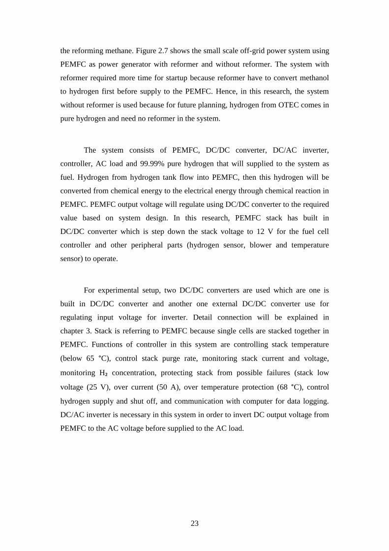
the reforming methane. Figure 2.7 shows the small scale off-grid power system using
PEMFC as power generator with reformer and without reformer. The system with
reformer required more time for startup because reformer have to convert methanol
to hydrogen first before supply to the PEMFC. Hence, in this research, the system
without reformer is used because for future planning, hydrogen from OTEC comes in
pure hydrogen and need no reformer in the system.
The system consists of PEMFC, DC/DC converter, DC/AC inverter,
controller, AC load and 99.99% pure hydrogen that will supplied to the system as
fuel. Hydrogen from hydrogen tank flow into PEMFC, then this hydrogen will be
converted from chemical energy to the electrical energy through chemical reaction in
PEMFC. PEMFC output voltage will regulate using DC/DC converter to the required
value based on system design. In this research, PEMFC stack has built in
DC/DC converter which is step down the stack voltage to 12 V for the fuel cell
controller and other peripheral parts (hydrogen sensor, blower and temperature
sensor) to operate.
For experimental setup, two DC/DC converters are used which are one is
built in DC/DC converter and another one external DC/DC converter use for
regulating input voltage for inverter. Detail connection will be explained in
chapter 3. Stack is referring to PEMFC because single cells are stacked together in
PEMFC. Functions of controller in this system are controlling stack temperature
(below 65 °C), control stack purge rate, monitoring stack current and voltage,
monitoring H₂ concentration, protecting stack from possible failures (stack low
voltage (25 V), over current (50 A), over temperature protection (68 °C), control
hydrogen supply and shut off, and communication with computer for data logging.
DC/AC inverter is necessary in this system in order to invert DC output voltage from
PEMFC to the AC voltage before supplied to the AC load.

24
(a)
(b)
Figure 2.7 Small scale off-grid power system using PEMFC as power generator;
(a) with reformer (b) without reformer
To get big scale PEMFC off-grid power system, small unit of PEMFC can be
stacked together. The Dutch fuel cell manufacturer (Nedstack), run a project of
Solvay 1 MW PEMFC Project. In this project, 168 units of 10 kW PEMFC are
stacked up together to get peak power 1.7 MW PEMFC. However, output power is
1 MW with 60% efficiency [56]. This project has been installed in Solvay chlorine
plant in Lillo, Belgium. Nedstack is working on the project called
DEMCOPEM-2 MW to build 2 MW PEMFC in Yingkaou, China and target to be
completed by the end of 2018 [57]. This project is completed and installed on site at
Ynnovate Sanzheng (Yingkou) [58]. Figure 2.8 shows the DEMCOPEM-2 PEMFC
Power Plant at Ynnovate, Yingkou.
Hydrogen
Tank
PEMFC DC/DC
Converter
DC/AC
Inverter
AC
Load
Controller
Reformer PEMFC DC/DC
Converter
DC/AC
Inverter
AC
Load
Controller

25
Figure 2.8 DEMCOPEM-2 PEMFC power plant at Ynnovate, Yingkou [58]
2.3 Overview of Hydrogen
Hydrogen is energy carrier that can be converted to produce electricity.
Steam Methane Reforming (SMR) and water electrolysis are methods to produce
hydrogen. Equation (2.2) and Equation (2.3) show chemical reaction of extracting
hydrogen from natural gas (methane). SMR consists of two steps, first step is
methane reforming takes place in the present of catalyst at temperature
(500°C to 900°C) and pressure 30 atm. Second, CO then reacts with steam to produce
H₂ and CO₂. Figure 2.9 shows the steam reformer which is steam from the heater is
mix with flammable gas, which contains methane to begin the response.
The steam-gas mixture enters the reformer from the inlet manifold.
The transforming tubes are encompassed by burners, keeping at high temperature.
At high temperatures, methane (CH₄) responds with steam (H₂O) to deliver hydrogen
(H₂) and carbon monoxide (CO). The present of a nickel catalyst enables this
procedure to respond all the more rapidly and to hold more hydrogen gas.
The hydrogen-carbon monoxide mixture leaves the reformer via cold outlet manifold
system. Carbon monoxide is definitely not a helpful result of the response and might
be unsafe whenever discharged into the earth [59].

26
( ) ₂ ( ) ₂( ) ( ) (2.2)
CO(g)+H₂O(g)→H₂(g)+CO₂(g) (2.3)
Figure 2.9 Steam reformer [59]

27
Figure 2.10 Standard electrolysis [60]
Equation (2.4) shows chemical reaction of extracting hydrogen from water
which is water separated into hydrogen and oxygen using electrolysis process.
Electrolyzer is electrochemical device that utilize an electric current to separate a
water particle (H₂O) into hydrogen (H₂) and oxygen (O₂). At the cathode, reduction
reaction occur which is electron from cathode is given to hydrogen cations to form
hydrogen gas. At the anode, oxidation reaction occur which is oxygen lost electron to
form oxygen gas. Hydrogen can be produced via electrolysis of water from any
electrical source, including utility grid power, PV, wind power, hydropower, nuclear
power or OTEC. Electrolyzer has a positive and negative side, similar to a battery.
Hydrogen gas is created on the negative side while oxygen gas is produced on the
positive side as shown in Figure 2.10. If attach empty tubes or cylinders to either
side, gases can be collected.

28
₂ ( ) ₂( ) ₂( ) (2.4)
One of the reason hydrogen became popular as future energy is because of its
cleanliness. Cleanliness of power system using hydrogen fuel depends on hydrogen
production method. Producing hydrogen from OTEC water electrolysis can keep
cleanliness of power system using hydrogen fuel. Table 2.6 shows cost of hydrogen
based on OTEC size. The bigger the size of OTEC plant, the less the cost of
hydrogen production [44].
Table 2.6 Cost of hydrogen based on OTEC size [44]
Nominal Plant Size OTEC (MW) Cost of Hydrogen in $/kg
10.00 14.48
35.00 7.22
50.00 6.66
53.50 5.07
100.00 4.75
29
CHAPTER 3
RESEARCH METHODOLOGY
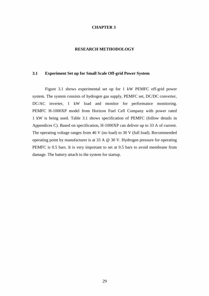
3.1 Experiment Set up for Small Scale Off-grid Power System
Figure 3.1 shows experimental set up for 1 kW PEMFC off-grid power
system. The system consists of hydrogen gas supply, PEMFC set, DC/DC converter,
DC/AC inverter, 1 kW load and monitor for performance monitoring.
PEMFC H-1000XP model from Horizon Fuel Cell Company with power rated
1 kW is being used. Table 3.1 shows specification of PEMFC (follow details in
Appendices C). Based on specification, H-1000XP can deliver up to 33 A of current.
The operating voltage ranges from 46 V (no load) to 30 V (full load). Recommended
operating point by manufacturer is at 33 A @ 30 V. Hydrogen pressure for operating
PEMFC is 0.5 bars. It is very important to set at 0.5 bars to avoid membrane from
damage. The battery attach to the system for startup.

30
Hydrogen Gas
Monitor
1 kW Load
PEMFC Set
DC/DC Converter DC/AC Inverter
Battery
Figure 3.1 Experimental set up for PEMFC off-grid power system

31
Table 3.1 Specification of 1 kW PEMFC [61]
Category Value
Type of fuel cell PEM
Physical Number of cells 50
Dimensions 264mm x 203mm x 104mm
Weight 11.7kg
Performance Peak Power 1000W
Rated current 0 - 33.5A @30V
DC Voltage 25V - 48V
Fuel Reactants Hydrogen and air
Composition 99.99% dry H₂
H₂ pressure 0.50 - 0.65 bar
Hydrogen Consumption @1000W
or flowrate
12.5 SLPM (standard liter
per minute)
Operation External Temperature 5-35°C
Max stack temperature 65°C
Humidification Self-humidified
Cooling Air
Start up battery 12 V
Monitoring RS232 System Status/Historical
data

32
Figure 3.2 Polarization curve for H-1000XP [61]
Figure 3.2 shows polarization curve for H-1000XP from user manual
provided by manufacturer. Graph shows at no load, PEMFC output voltage is 48 V.
When current increase, PEMFC output voltage will drop. For 1 kW output power,
voltage is 36 V and current is 30 A.
Figure 3.3 Hydrogen consumption rate at different output power [61]
0
2
4
6
8
10
12
14
100 200 300 400 500 600 700 800 900 1000
Hyd
roge
n C
on
sum
tio
n R
ate
(L/
min
)
PEMFC Output Power (W)

33
Figure 3.3 shows the hydrogen consumption rate at different output power
based on H-1000XP user manual. More hydrogen consumes by PEMFC to deliver
more power. Figure 3.4 shows AC load which indicate power of each bulb is 100 W.
To test amount of power that PEMFC can deliver to the load, switch is on one by
one. One switch controls one bulb and load power has been tested with increment
step of 100 W.
Figure 3.4 Alternate Current (AC) load

34
Figure 3.5 Electrical circuit diagram for H-1000XP [61]
Figure 3.5 shows electrical circuit diagram for H-1000XP. Hydrogen supplies
to the PEMFC at 0.5 bars. In this system, there are two valves available. Supply
valve is for hydrogen supply and purge valve is for purging out hydrogen when
PEMFC is not in use to avoid damage on membrane. Pressure regulator usage is to
control hydrogen supplied at constant pressure. Then, battery is being connected for
startup the system and power on hydrogen sensor. Hydrogen will trigger alarm if
there is leakage of hydrogen. After that, press switch for about 3 seconds until the
system is on. Temperature sensor and blower are necessary to maintain stack
temperature below than 65°C to avoid stack damage. The system connects to the
laptop for monitoring of ambient temperature, stack power, battery voltage,
stack temperature, stack voltage and stack current. H-1000XP set includes
internal DC/DC converter is for regulating the output voltage of PEMFC controller at
12 V for the fuel cell controller to operate. Functions of controller in this system
aforementioned in chapter 2 are for controlling stack temperature (below 65 °C),
control stack purge rate, monitoring stack current and voltage, monitoring H₂
concentration, protecting stack from possible failures (stack low voltage (25 V),

35
over current (50 A), over temperature protection (68 °C), control hydrogen supply
and shut off, and communication with computer for data logging. Ultracapacitor can
supply power output during system short circuiting which could enable system
continuous operation without external power supply.
Electrical circuit diagram from user manual shows example for motor as a
load. In this study, AC load which is bulb is being used as a load. Figure 3.6 shows
electrical circuit diagram for supplying power to the AC load. External DC/DC
converter is connected to output connecter to regulate the voltage at 36 V to supply
to the DC/AC inverter from Swipower Company. DC/AC inverter inverts DC output
voltage of PEMFC to AC voltage. DC input voltage range of inverter is between
30 V to 45 V (details in Appendices D).
Figure 3.6 Electrical circuit diagram for H-1000XP with external DC/DC
converter and DC/AC inverter [61]
36
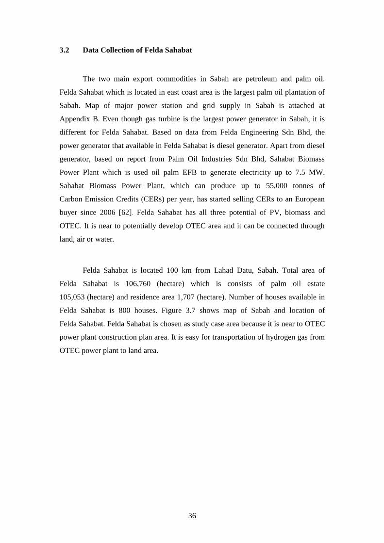
3.2 Data Collection of Felda Sahabat
The two main export commodities in Sabah are petroleum and palm oil.
Felda Sahabat which is located in east coast area is the largest palm oil plantation of
Sabah. Map of major power station and grid supply in Sabah is attached at
Appendix B. Even though gas turbine is the largest power generator in Sabah, it is
different for Felda Sahabat. Based on data from Felda Engineering Sdn Bhd, the
power generator that available in Felda Sahabat is diesel generator. Apart from diesel
generator, based on report from Palm Oil Industries Sdn Bhd, Sahabat Biomass
Power Plant which is used oil palm EFB to generate electricity up to 7.5 MW.
Sahabat Biomass Power Plant, which can produce up to 55,000 tonnes of
Carbon Emission Credits (CERs) per year, has started selling CERs to an European
buyer since 2006 [62]. Felda Sahabat has all three potential of PV, biomass and
OTEC. It is near to potentially develop OTEC area and it can be connected through
land, air or water.
Felda Sahabat is located 100 km from Lahad Datu, Sabah. Total area of
Felda Sahabat is 106,760 (hectare) which is consists of palm oil estate
105,053 (hectare) and residence area 1,707 (hectare). Number of houses available in
Felda Sahabat is 800 houses. Figure 3.7 shows map of Sabah and location of
Felda Sahabat. Felda Sahabat is chosen as study case area because it is near to OTEC
power plant construction plan area. It is easy for transportation of hydrogen gas from
OTEC power plant to land area.

37
Figure 3.7 Location of Felda Sahabat [63]
Based on data provided by Felda Engineering Sdn Bhd, total diesel generator
capacity available in Felda Sahabat is 10,785 kW. Table 3.2 shows list of diesel
generators in Felda Sahabat. There are 10 stations available which are
Stesen Janakuasa Bandar Sahabat or Desa Kencana (SJBS/DK), Stesen Janakuasa
Anjung Tanah (SJAT), Stesen Janakuasa Cenderawasih (SJC), Stesen Janakuasa
Baiduri Ayu (SJBA), Stesen Janakuasa Embara Budi (SJEB), Stesen Janakuasa Fajar
Harapan (SJFH), Stesen Janakuasa Gemala Pura (SJGP), Stesen Janakuasa
Hamparan Badai (SJHB), Stesen Janakuasa Jeragan Bestari (SJJB) and
Stesen Janakuasa Kembara Sakti (SJKS). Normally, installation of diesel generator
capacity is bigger than amount of required load. Load utilize from diesel generator
power plant is 80%. Based on this data, estimation for suitable electrical power plant
capacity for Felda Sahabat is 8,628 kW which is 80% from total diesel generator
capacity available in Felda Sahabat. This value will be used for estimation
specification for large PEMFC power plant.
Using diesel as fuel can harm environment. Besides that, noise from diesel
generator is annoying to surrounding people. For future, demand for clean and
renewable energy is increasing and diesel generator usage should be reduced. Due to

38
this, off-grid power system using hydrogen fuel is good option to provide electricity
to this area in the future.
Table 3.2 List of available diesel generator in Felda Sahabat [64]
No. Station Location Model
Engine Alternator Capacity
(kW)
1 SJBS/
DK
Bandar
Sahabat
Cummins / VTA28G5 LEROY SUM 500
Cummins / KTA38 MARATHON 800
Cummins / KTA38 STANDFORD 800
Cummins /KTA38 STANDFORD 800
TOTAL 2900
2 SJAT Anjung Tanah Cummins/ KTA19-G4 MARATHON 400
Cummins/KTA19-G4 MARATHON 400
Cummins/NTA855G2 LEROY SUM 250
Cummins/NTA855G2 LEROY SUM 250
TOTAL 1300
3 SJC Cenderawasih Cummins / KTA38 STANDFORD 800
Cummins / KTA38 MARATHON 800
Cummins /VTA28G5 STANDFORD 500
Cummins /VTA28G5 STANDFORD 500
TOTAL 2600
4 SJBA Baiduri Ayu Cummins/6CT8.3G CBR128
(STDFD)
125
Cummins/6CT8.3G CBR128
(STDFD)
125
Cummins/6CT8.3G STANDFORD 125
Cummins/6BT5.3G STANDFORD 60
TOTAL 435

39
Table 3.2 Continued
No. Station Location Model
Engine Alternator Capacity
(kW)
5 SJEB Embara Budi Cummins/LTA10G3 MARATHON 200
Cummins/LTA10G4 MARATHON 200
Cummins/6CT8.3G CBR128 125
Cummins/6CT8.3G CBR128 125
TOTAL 650
6 SJFH Fajar Harapan Cummins/6CT8.3G STANDFORD 125
Cummins/6CT8.3G STANDFORD 125
Cummins/NTA855G2 MARATHON 250
TOTAL 500
7 SJGP Gemala Pura Cummins/6CT8.3G MARATHON 125
Cummins/6CT8.3G MARATHON 125
Cummins/LTA10G4 MARATHON 200
TOTAL 450
8 SJHB Hamparan Badai Cummins/6CT8.3G MARATHON 125
Cummins/6CT8.3G MARATHON 125
Cummins/LTA10G4 MARATHON 200
TOTAL 450
9 SJJB Jeragan Bistari Cummins/6CT8.3G MARATHON 125
Cummins/6CT8.3G MARATHON 125
Cummins/LTA10G4 MARATHON 200
TOTAL 450
10 SJKS Kembara Sakti Cummins/KTA19-G4 MARATHON 400
Cummins/KTA19-G4 MARATHON 400
Cummins/NTA855G2 MARATHON 250
TOTAL 1050
GRAND TOTAL 10785


41
CHAPTER 4
RESULTS AND DISCUSSION
4.1 Experimental Result of Small Scale Off-grid Power System
Figure 4.1 until Figure 4.6 show ambient temperature, stack temperature,
battery voltage, stack power, stack current and stack voltage value at load value 0 W,
100 W, 200 W, 300 W, 400 W and 500 W. Please refer to Appendix E for location of
ambient temperature sensor measurement.
Each steps in Figure 4.6 shows that load power increase by 100 W.
Stack power increase when load power increase. Graph in Figure 4.6 shows that
when load power increase, the step for PEMFC output power increase steeply. From
this, it concludes that PEMFC is able to adjust quickly based on required load
demand and cause no power outage for consumer side. When load power increase,
more current derive from PEMFC stack and more hydrogen flow into the PEMFC to
deliver more power. When load power demand change to 500 W, PEMFC output
power become unstable and power drop as shown in Figure 4.6. This result indicate
that maximum power that can be delivered by PEMFC H-1000XP is 400 W. It shows
that PEMFC H-1000XP only can supply about 40% of rated power. This information
is important as guideline to estimate electrical specification for bigger size system.
Value of ambient temperature, stack temperature, battery voltage, stack current, stack
voltage and stack power is tabulated in Table 4.1.

42
Figure 4.1 Stack power, stack current and stack voltage at 0 W
Figure 4.2 Stack power, stack current and stack voltage at 100 W

43
Figure 4.3 Stack power, stack current and stack voltage at 200 W
Figure 4.4 Stack power, stack current and stack voltage at 300 W

44
Figure 4.5 Stack power, stack current and stack voltage at 400 W
Figure 4.6 Stack power, stack current and stack voltage at 500 W

45
Table 4.1 Ambient temperature, stack temperature, battery voltage, stack
current, stack voltage and stack power at different load power
Load
Power
(W)
Ambient
Temperature
(°C)
Stack
Temperature
(°C)
Battery
Voltage
(V)
Stack
Current
(A)
Stack
Voltage
(V)
Stack
Power
(W)
0 20.00 24.50 14.10 1.40 40.33 56.47
100 20.50 26.50 14.00 4.40 36.67 161.33
200 20.50 32.00 14.10 7.60 34.67 263.47
300 20.50 35.00 14.10 10.40 33.00 343.20
400 21.00 41.00 14.10 12.80 32.33 413.87
500 - - - - - -
*No data recorded for load 500 W because PEMFC is not stable
4.2 OPEX for Small Scale PEMFC
Calculation doing based on project life time 25 years. Table 4.2 shows
lifetimes assumption for system components. Lifetime for PEMFC is 1000 hours.
Assume PEMFC is being operated 24 hours per day. One set of PEMFC can operated
for about 41 days. In 25 years, PEMFC set need to be replaced for 222 times.
Total cost of replacement is RM7, 276, 050. Lifetime for startup battery is 5 years.
In 25 years, battery is needed to replace 5 times. Total cost for battery replacement in
25 years is RM360. For DC /DC converter and DC/AC inverter, assumes lifetime are
25 years, replacement cost in 25 years is RM 0.
Table 4.2 Lifetimes assumption for system components
Components Cost (RM) Lifetime Replacement Cost
(RM/25 years)
PEMFC H-1000XP
set (1 kW)
32,775.00 1000 hours 7,276,050
Startup battery 72.00 5 years 360
DC/DC converter 57.70 25 years 0
DC/AC inverter 500.00 25 years 0
Total 33, 404.70 7, 276, 410

46
For operating PEMFC small scale off-grid power system, hydrogen
consumption will be the biggest portion for the operational expenditure cost.
Hydrogen consumption rate for 1 kW H-1000XP is 12 liter per minutes. In the
experiment, a compressed hydrogen cylinder with capacity 47 liter is used.
The purity of hydrogen is 99.99%. and cost of hydrogen cylinder is RM249.80.
Number of hours for operating PEMFC at power rated 1 kW is 0.07 hours as shown
in Equation (4.1). The cost of operating 1 kW PEMFC for 0.07 hours using only one
cylinder is RM249.80. This is equivalent to RM3568.57 per kilowatt hour.
This calculation based on price of hydrogen supplied at Kuala Lumpur during time of
experiment.
(4.1)
Cost of hydrogen production from electrolysis process by 100 MW OTEC
plant size is $4.75/kg [44]. 1 kg of hydrogen is equal to 14.128 liter of hydrogen.
Converting to liter, the price is $0.336212 per liter. Using currency rate as
31st December 2018, RM1 is equal to $0.24, price for hydrogen is RM1.40 per liter.
This is price for hydrogen production at OTEC power plant. Assume the price sell to
the customer is about 50% higher than production cost, the price become
RM2.10 per liter. Assume the hydrogen supply from OTEC using the same cylinder
size, for one tank of hydrogen, RM2.10 multiple with 47 liter, the price for one tank
of hydrogen is RM98.70. By using hydrogen from OTEC, to operate 1 kW PEMFC
for 0.07 hours is RM 98.70. To operate for one hour, RM98.70 divided with
0.07 hours, equivalent to RM1,410 per kilowatt hour. Assume PEMFC operates
24 hours, for one day cost of hydrogen consumption is RM33, 840. To operate in one
year, RM33, 840 multiple with 365 days, cost for one year is RM12, 351, 600.
To operate for 25 years, the cost will be RM308, 790, 000.
To operate small scale of off-grid system using PEMFC in 25 years, total cost
is cost for components replacement in 25 years plus with hydrogen consumption for
25 years. Total cost for replacement is RM7, 276, 410 and total cost for hydrogen
47
consumption is RM308, 790, 000, resulted in RM316, 066, 410 for total operational
cost in 25 years.
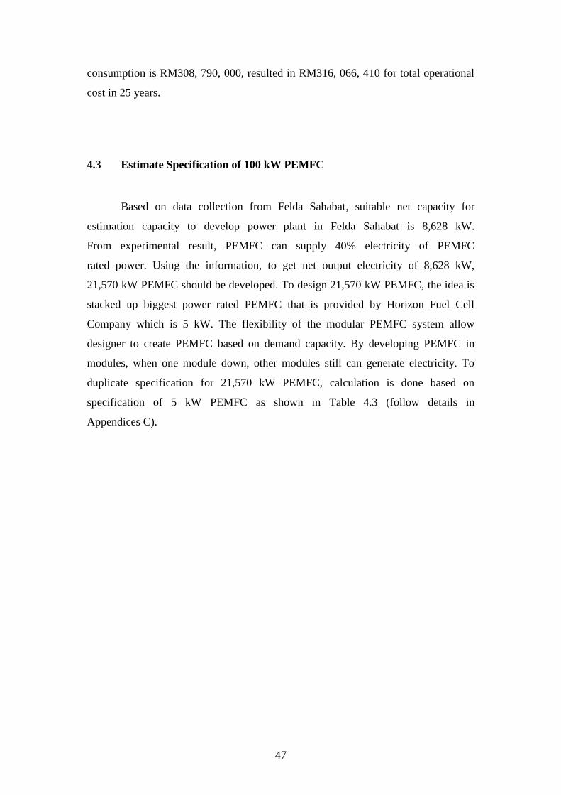
4.3 Estimate Specification of 100 kW PEMFC
Based on data collection from Felda Sahabat, suitable net capacity for
estimation capacity to develop power plant in Felda Sahabat is 8,628 kW.
From experimental result, PEMFC can supply 40% electricity of PEMFC
rated power. Using the information, to get net output electricity of 8,628 kW,
21,570 kW PEMFC should be developed. To design 21,570 kW PEMFC, the idea is
stacked up biggest power rated PEMFC that is provided by Horizon Fuel Cell
Company which is 5 kW. The flexibility of the modular PEMFC system allow
designer to create PEMFC based on demand capacity. By developing PEMFC in
modules, when one module down, other modules still can generate electricity. To
duplicate specification for 21,570 kW PEMFC, calculation is done based on
specification of 5 kW PEMFC as shown in Table 4.3 (follow details in
Appendices C).

48
Table 4.3 Specification of 5 kW PEMFC Category Value
Type of fuel cell PEM
Physical Number of cells 120
Dimensions 650mm x 350mm x 212mm
Weight stack 32.5 kg
Performance Peak Power 5000W
Rated current 0 - 70A @72V
DC Voltage 60V - 72V
Fuel Reactants Hydrogen and air
Composition 99.99% dry H₂
H₂ pressure 0.50 - 0.65 bar
Hydrogen Consumption @5000W or
flowrate
65 SLPM(standard liter per
minute)
Operation External Temperature 5-30°C
Max stack temperature 65°C
Humidification Self-humidified
Cooling Air
Start up battery 24 V
Monitoring RS232 System Status/Historical data

49
Figure 4.7 Modular system for 21, 570 kW PEMFC
To get 21,570 kW PEMFC, 216 units of modular 100 kW PEMFC can be
developed. Figure 4.7 shows the modular system for 21,570 kW PEMFC which each
modular capacity is 100 kW. Each PEMFC array consists of 20 units 5 kW PEMFC
connected in series. Output voltage for 100 kW is 1.2 kV to 1.44 kV
(details calculation refer to Equation (4.6) and Equation (4.7)). For distribution,
output voltage can be step up to 11 kV using step up transformer to deliver electricity
to the industrial customer which is palm oil mill in Felda Sahabat and can be step
down to 240 V to supply electricity to the Felda Sahabat resident.
To get 100 kW PEMFC, 20 units of 5 kW PEMFC is needed as per shown in
Equation (4.2). To get number of cells for 100 kW, number of cells for 5 kW
PEMFC which is 120 cells multiple with 20 as shown in Equation (4.3). Thus,
number of cells for 100 kW PEMFC is 2,400 cells.
units PEMFC
(4.2)

50
(4.3)
To calculate dimension for 100 kW PEMFC, dimension for 100 kW PEMFC
is 20 times bigger than 5 kW PEMFC, calculation is done based on Equation (4.4)
and total size is 385.84 m³. Assume bigger size about 30% for the auxiliary
component such as battery, DC/DC converter, DC/AC inverter and hydrogen supply,
result for total size will be 501.592 m³.
( ) ( ) ( )
(4.4)
(4.5)
Equation (4.5) shows calculation for weight. For voltage, total voltage will be
1200 V to 1440 V as per shown in Equation (4.6) and Equation (4.7).
(4.6)
(4.7)
For type of fuel cell, reactants, composition, H₂ pressure,
external temperature, maximum stack temperature, humidification, cooling and
monitoring system are remain the same with 5 kW PEMFC specification. 20 batteries
with voltage 24 V is needed for startup. For hydrogen consumption, total amount is
1,300 Standard Liter Per Minute (SLPM) as per shown in Equation (4.8).
Table 4.4 shows estimation specification for 100 kW PEMFC.
(4.8)

51
Table 4.4 Estimation specification for 100 kW PEMFC
Category Value
Type of fuel cell PEM
Physical Number of cells 2,400
Dimensions 501.592 m³
Weight 650 kg
Performance Peak Power 100 kW
Rated current 0-70A
DC Voltage 1200V - 1440V
Fuel Reactants Hydrogen and air
Composition 99.99% dry H₂
H₂ pressure 0.50 - 0.65 bar
Hydrogen Consumption @1MW
or flowrate
1,300 SLPM (standard liter per
minute)
Operation External Temperature 5-35°C
Max stack temperature 65°C
Humidification Self-humidified
Cooling Air
Start up battery 24 V x 20
Monitoring RS232 System Status/Historical data


53
CHAPTER 5
CONCLUSION AND RECOMMENDATIONS
From this study, several points are concluded and some recommendations for
future work are being highlighted.
5.1 Conclusion
From this study, it can be concluded that experimental result using 1 kW
H-1000XP shows that efficiency of the PEMFC small scale power system is 40%.
For proposing the capacity of bigger scale of PEMFC off-grid power system to
Felda Sahabat, 21,570 kW PEMFC off-grid power system is suitable to get net power
output at 8,628 kW. Operational expenditure cost assumption for 1 kW PEMFC
H-1000XP using hydrogen from OTEC for 25 years is RM316, 066, 410. Electrical
specification of 1 modular 100 kW PEMFC output voltage and output current is
1.2 kV to 1.44 kV and 0 A to 70 A, respectively. 216 units of 100 kW modular
PEMFC is required to get net output 8,628 kW for PEMFC off-grid installation
proposal for Felda Sahabat, Sabah. This study can be baseline for Felda Sahabat and
other organizations for developing PEMFC off-grid power system using hydrogen
from OTEC in the future.
54
5.2 Recommendation
To calculate more accurate cost of implementation off-grid power system
using PEMFC, cost of distribution cable, protection system, transformer for power
distribution should be included. Monitoring system should be installed to monitor
amount of hydrogen as proactive action to avoid hydrogen from being out of stack.
Hydrogen supply is very important for PEMFC, because without hydrogen PEMFC
cannot generate electricity.
Felda Sahabat should integrate biomass power plant with PEMFC as backup
during biomass power plant maintenance. Instead of only using hydrogen supply
from OTEC, study on how to utilize methanol from palm oil landfill should carry out
as another alternative to fully utilize waste from palm oil production.
Study for implementation PEMFC as distribute generation to the houses area
with low density of resident is good option to supply electricity in remote area in
Sabah. Villagers should be trained to manage their own PEMFC at their house and
this is practical because PEMFC is easy to operate and need no difficult maintenance
to maintain the system. Integration of PEMFC with electrolyzer to produce hydrogen
onsite is also good idea to remote area which are difficult to get hydrogen supply
from outside.
With the flexibility to install PEMFC either for standalone or hybrid, it is
recommended to utilize this technology for electricity generation when PEMFC and
OTEC technology are matured enough to compete with conventional electricity
generation in term of cost.

55
REFERENCES
1. Neil Brian Joseph (2018, October 24) Federal working with state to resolve
power issue – Yeo. Borneo Post Online. Retrieved January 1, 2019 from
http://www.theborneopost.com/2018/10/24/federal-working-with-state-to-
resolve-power-issues-yeo/
2. Energy Commision.Malaysia Energy Statistic Handbook 2017
3. Z. Marziah, A. Azhim, A. Mahdzir, M. N. Musa and A. B. Jaafar. Potential of
Deep Seawater Mariculture for Economic Transformation in Sabah,
Malaysia. 10th Asian Control Conference. May 31- June 3, 2015. Kota
Kinabalu, Sabah: IEEE. 2015. 1-6.
4. A. Hossain, A. Azhim, A. B. Jaafar, M. N. Musa, S. A. Zaki and D. N.
Fazreen. Ocean Thermal Energy Conversion: The Promise of a Clean Future.
IEEE Conference on Clean Energy and Technology. November 18-20, 2013.
Langkawi, Malaysia: IEEE. 2013. 23-26.
5. Ibrahim Tabir (2018, November 6) Lahad Datu folks want electricity supply
reconnected. Daily Express. Retrieved November 14, 2018 from
https://www.sesb.com.my/news/ld-folks-want-electricity-supply-reconnected
6. (2017, July 18) Sabah SAIDI 100 lab to find permanent solutions to
electricity problem. Borneo Today. Retrieved November 15, 2018 from
https://www.borneotoday.net/sabah-saidi-100-lab-to-find-permanent-
solutions-to-electricity-problem/
7. Energy Commision.Sabah Electricity Supply Industry Outlook 2015
8. (2018, July 25) Electricity grid in Sabah set for upgrade. The Star. Retrieved
November 19, 2018 from https://www.thestar.com.my/metro/metro-
news/2018/07/25/electricity-grid-in-sabah-set-for-upgrade-projects-costing-
rm840mil-will-boost-supply-from-west-coas/
9. (2018, August 22) 603 villages yet to enjoy power supply. Daily Express.
Retrieved November 19, 2018 from
http://www.dailyexpress.com.my/news.cfm?NewsID=126701

56
10. J. Hazelton, A. Bruce and L. Macgill. Improving Risk Management for
Utility PV-Battery-Diesel –Mini Grid Project in Sabah. Asia Pacific Solar
Research Conference 2015. December, 2015. Brisbane, Australia.
11. Mahmud, A.M. and Blanchard, R.E. Assessing a Rural Electrification
Program in Malaysia: System Performance Analysis on 11 Solar PV-diesel
Hybrid Systems. 4th International Conference on Development in Renewable
Energy Technology (ICDRET) 2016. January 7-9, 2016. Dhaka, Bangladesh.
12. Lifespan of lead acid battery from https://www.quora.com/What-is-the-
lifespan-of-a-lead-acid-battery (Accessed: November 19, 2018)
13. M. Faisal, M. A. Hannan, and P. J. Ker. Review of Energy Storage System
Technologies in Microgrid Applications: Issues and Challenges. IEEE
Access. 2018. 6: 35143-35164.
14. Palm Oil Indstries Sdn Bhd. Sahabat Empty Fruit Bunch Biomass Project.
Clean Development Mechanism Simplified Project Design Document for
Small Scale Project Activity. 2003. Malaysia: Palm Oil Industries Sdn Bhd.
2003
15. Department of Statistics Malaysia, Official Report. Retrieved January 1, 2019
from
https://www.dosm.gov.my/v1/index.php?r=column/cone&menu_id=dTZ0K2
o4YXgrSDRtaEJyVmZ1R2h5dz09
16. M. S. Shaari, Hafizah A.B Rahim, and Intan M.A.R. Relationship among
Population, Energy Consumption and Economic Growth in Malaysia. The
International Journal of Social Sciences. 2013. 13: 39-45
17. Myjessie Songkin, N.N Barsoum, and Farrah Wong. Study on Sabah Grid
Stability. 2017 IEEE 2nd International Conference on Automatic Control and
Intelligent Systems (I2CACIS 2017), October 21, 2017, Kota Kinabalu,
Sabah, Malaysia
18. S. Joshi, V. Pandya and B. Bhalja, Hybrid Wind Photovoltaic Standalone
System. 2016 IEEE 6th International Conference on Power Systems (ICPS),
New Delhi, 2016.1-5.

57
19. A. W. A. Al-Fatlawi, R. Saidur and N. A. Rahim. Researching Social
Acceptability of Renewable-Energy Technology in Malaysia.
3rd International Conference on Clean Energy and Technology. November
24-26, 2014. Kuching, Sarawak: IEEE. 2014. 1-5.
20. Department of Energy Management and Industry Development Energy
Commission. Energy Outlook: Electricity Supply in Sabah. 2014. Malaysia:
Energy Commission. 2014
21. J. Sulaiman, A. Azman, and B. Saboori. Development of Solar Energy in
Sabah Malaysia: The Case of Trudgill’s Perception. 2014. International
Journal of Sustainable Energy and Environmental Research. 3: 90-99
22. SEDA website : https://pvms.seda.gov.my (Accessed December 3, 2018)
23. Charge traction battery from https://www.tvh.com/en-my/blog/how-do-i-
correctly-charge-traction-batteries (Accessed : December 4, 2018)
24. W. L. Jing, C. H. Lai, and W. S. H. Wong. Cost Analysis of Battery-
Supercapacitor Hybrid Energy Storage System for Standalone PV Systems.
4th IET Clean Energy and Technology Conference (CEAT. 2016).
Kuala Lumpur. 2016. 1-6.
25. M. I. Fahmi, R. K. Rajkumar, and R. Arelhi. Study on the Effect of
Supercapacitors in Solar PV system for Rural Application in Malaysia.
2015 50th International Universities Power Engineering Conference
(UPEC). Stoke on Trent, England. 2015. 1-5.
26. N. Tlili, B. Neily and F. Ben Salem. Modeling and Simulation of Hybrid
System Coupling a Photovoltaic Generator, a PEM Fuel Cell and an
Electrolyzer (Part I). 2014 IEEE 11th International Multi-Conference on
Systems, Signals & Devices (SSD14). Barcelona. 2014. 1-8.
27. K. Suzuki, N. Tsuji, and Y. Shirai. Evaluation of Biomass Energy Potential
Towards Achieving Sustainability in Biomass Energy Utilization in Sabah,
Malaysia. Biomass and Bioenergy. 97.2017: 149-154
28. SEDA website FiAH listing from
http://www.seda.gov.my/?omaneg=000101000000010101010001000010000
00000000000000000&s=1817 (Accessed January 1, 2019)

58
29. Julia Chan. (2016, August 5) Minister: Malaysia first geothermal plant to be
operational by 2018. Malay Mail. Retrieved December 13, 2018, from
https://www.malaymail.com/s/1177031/minister-malaysias-first-geothermal-
plant-to-be-operational-by-2018
30. L.C Sien and N.A. Osman. Development of Geothermal Plant in Malaysia: A
Case Study of Tawau Green Energy Project in Sabah.
Science and Technology National Conference 2015.Putrajaya, Malaysia.
2015.
31. Mukhriz Hazim (2018, December 6) Sabah geothermal power plant project
found abandoned, Dewan Rakyat told. Malay Mail. Retrieved December 13,
2018, from https://www.malaymail.com/s/1700621/sabah-geothermal-power-
plant-project-found-abandoned-dewan-rakyat-told
32. Abu Bakar Jaafar.(2012) Harnessing Ocean Thermal Energy From
Temperature Differentials of the Water Depth Off the Sabah Trough,
Malaysia. MIMA Buletin. 19 (1). 24-26
33. Mary Ann. OTEC in South East Asia. Available from
http://www.otecnews.org/2013/06/otec-in-south-east-asia/ [accessed January
23, 2018].
34. 32nd Exco Meeting, 10 and 11 April 2017. Ocean Energy System News
Bulletin. Retrieved December 23, 2018 from https://www.ocean-energy-
systems.org/newsletter.php?nID=17
35. K. Otsuka and K. Iio. Economic and Environmental Evaluations for Multi-
purpose Utilizations of Deep Ocean Water in Hateruma Island, Japan. 2016
Techno-Ocean. October 6-8, 2016. Kobe, Japan: IEEE. 2016. 217-220.
36. A. Shekarbaghani. Determine the Best Location for Ocean Thermal Energy
Conversion (OTEC) in Iranian Seas. Modern Applied Science. 2016. 10 (5):
32-40.
37. Vidya Mitra. 2017. Principles of generation of ocean thermal energy
conversion. Retrieved December 24, 2018 from
https://www.youtube.com/watch?v=0_1c69AWFY8

59
38. H. S. Das, C. W. Tan, A. H. M. Yatim and N. Din bin Muhamad. Modeling
and Simulation of Stand-alone Fuel Cell System for Distributed Generation
Application. 3rd International Conference on Electrical Engineering and
Information Communication Technology. September 22-24, 2016. Dhaka,
Bangladesh: IEEE. 2016. 1-6.
39. M. A. Rosli, N. Z. Yahaya and Z. Baharudin. Multi-input DC-DC Converter
for Hybrid Renewable Energy Generation System. 2014 IEEE Conference on
Energy Conversion. October 13, 2014. Johor Bahru, Malaysia: IEEE. 2014.
283-286.
40. Ocean Thermal Energy Conversion and Seawater District Cooling. Retrieved
January 1, 2019 from https://wefunder.com/otecorporation
41. A. Khaligh and C. Onar. Energy Harvesting: Wind, solar and ocean energy
conversion systems. United States of America: Taylor and Francis Group.
2008
42. A. G. Neto, L. Hiron, F. M. Pimenta and R. R. Rodrigues. Northeast Brazil
Potential for Land-based OTEC Implementation. 2014 Ninth International
Conference on Ecological Vehicles and Renewable Energies. March 25-27,
2014. Monte-Carlo, Monaco: IEEE. 2014. 1-4.
43. W.H. Avery and C. Wu. Renewable Energy from the Ocean: A Guide of
OTEC. New York:Oxford University Press. 1994
44. S. Banarjee, M. N. Musa, and A. B. Jaafar Economic Assessment and
Prospect of Hydrogen Generated by OTEC as Future Fuel.
International Journal of Hydrogen Energy.42. 2017: 26-37
45. S. Goto, D. Iseri, and Y. Matsuda. Simulation Model of Evaporator and
Separator in OTEC Plant using Uehara Cycle for Liquid Level Control.
2012 Proceedings of SICE Annual Conference (SICE). Akita. 2012.
2088-2093.
46. H. Lade, V. Kumar and G. Arthanareeswaran. Sulfonated Poly(arylene ether
sulfone) Nanocomposites Electrolyte Membrane for Fuel Cell Applications.
A Review . International Journal of Hydrogen.2016. 12:2-13
47. N. M. Zahari and A. A. Aziz. Effect of Platinum Catalyst Loading on
Membrane Electrode Assembly (MEA) in Proton Exchange Membrane Fuel
Cell (PEMFC). 2012 10th IEEE International Conference on Semiconductor
Electronics. September 19-21, 2012. Kuala Lumpur: IEEE. 2012. 669-673.

60
48. Fuel Cell Store. Membrane Electrodes Assemblies (MEA). Retrieved
December 24, 2018 from https://www.fuelcellstore.com/fuel-cell-
components/membrane-electrode-assembly
49. M. Akai. Stationary Fuel Cell Program in Japan. International Energy Agency
Workshop. April 27-28, 2010. Paris: International Agency Energy. 2010.
1-54.
50. A. Maruta. Japan’s Ene-Farm Programme. Technova Inc. presentation at the
AFC Workshop in Vienna, 2016.
51. N. Ioannis, M. Andreas and N. Stavros. PEM Fuel Cell System Evaluation
Using Operational Data and Update Matlab/Simulink Tools.
7th Mediterranean Conference and Exhibition on Power Generation,
Transmission, Distribution and Energy Conversion. November 7-10, 2010.
Agia Napa, Cyprus: IEEE. 2010. 1-6.
52. J. Jia, D. Lian and Y.Wang. Matlab/Simulink Based-Study on PEM Fuel Cell
and Battery Hybrid System. 10th International Conference on Control,
Automation, Robotics and Vision. December 17-20, 2008. Hanoi, Vietnam:
IEEE. 2008. 2108-2113.
53. B. Gou, W. K. Na and B. Diong. Fuel Cells Modelling, Control and
Applications. United States: CRC Press Taylor & Francis Group. 2010
54. W. Chen, Y. Han and Q. Li. Design of Proton Exchange Membrane Fuel Cell
Grid-Connected System Based on Resonant Current Controller. International
Journal of Hydrogen Energy. 2014. 39(26): 14402-14410.
55. L. Stroyov, S. Patel and R. Ali. Innovative Fuel Cell Deployment in Telstra’s
Network and Key Learning from the Field. IEEE International
Telecommunications Technology Conference (INTELEC). 2017. Broadbeach,
QLD. 2017. 47-53.
56. Patrick Francoisse. Solvay 1 MW PEMFC Project. 3rd Stakeholders General
Assembly. November 9-10, 2010. Brussel: Fuel Cell and Hydrogen Joint
Undertaking. 2010. 1-14.
57. J. T. Have and Jorg Coolegem. DEMCOPEM-2MW: Demontsration of
Combined Heat and Power 2 MWe PEM Fuel Cell Generator and Integration
into an Existing Chlorine Production Plant. Belgium: Publication Office of
the Europian Union. 2016

61
58. Launching Ceremony in China of the World’s First 2 MW PEM Fuel Cell
Power Plant. Retrieved January 2, 2019 from http://www.demcopem-
2mw.eu/worlds-first-2mw-pem-fuel-cell-power-plant/
59. Kevin Bakey. The Production of Hydrogen Gas: Steam Methane Reforming.
English Technical Class Writing note – Process Description March 23, 2015
60. Horizon Energy Curriculum. Introduction to Electrolyzers and Fuel Cells.
Retrieved December 25, 2018) from
https://www.horizoncurriculum.com/supportmaterial/introduction-to-
electrolyzers-and-fuel-cells/
61. H-1000XP User Manual
62. Hanim Adnan and Edi Sarif.(February 11, 2012) Advocating green practices.
The Star. Retrieved January 2, 2019 from
https://www.thestar.com.my/business/business-news/2012/02/11/advocating-
green-practices/
63. Google Map application from website
https://www.google.com/maps/search/felda+sahabat+sabah/@5.695637,116.5
052523,8z (Accessed : January 17, 2019)
64. List of Diesel Generator in Felda Sahabat, Sabah. Felda Engineering Sdn Bhd


63
Appendix A Website Photovoltaic Monitoring System by SEDA Malaysia

64
Appendix B Major Power Station and Grid Supply in Sabah
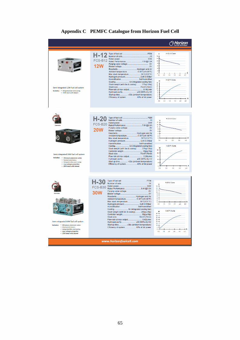
65
Appendix C PEMFC Catalogue from Horizon Fuel Cell

66

67

68

69
Appendix D Specification of Inverter
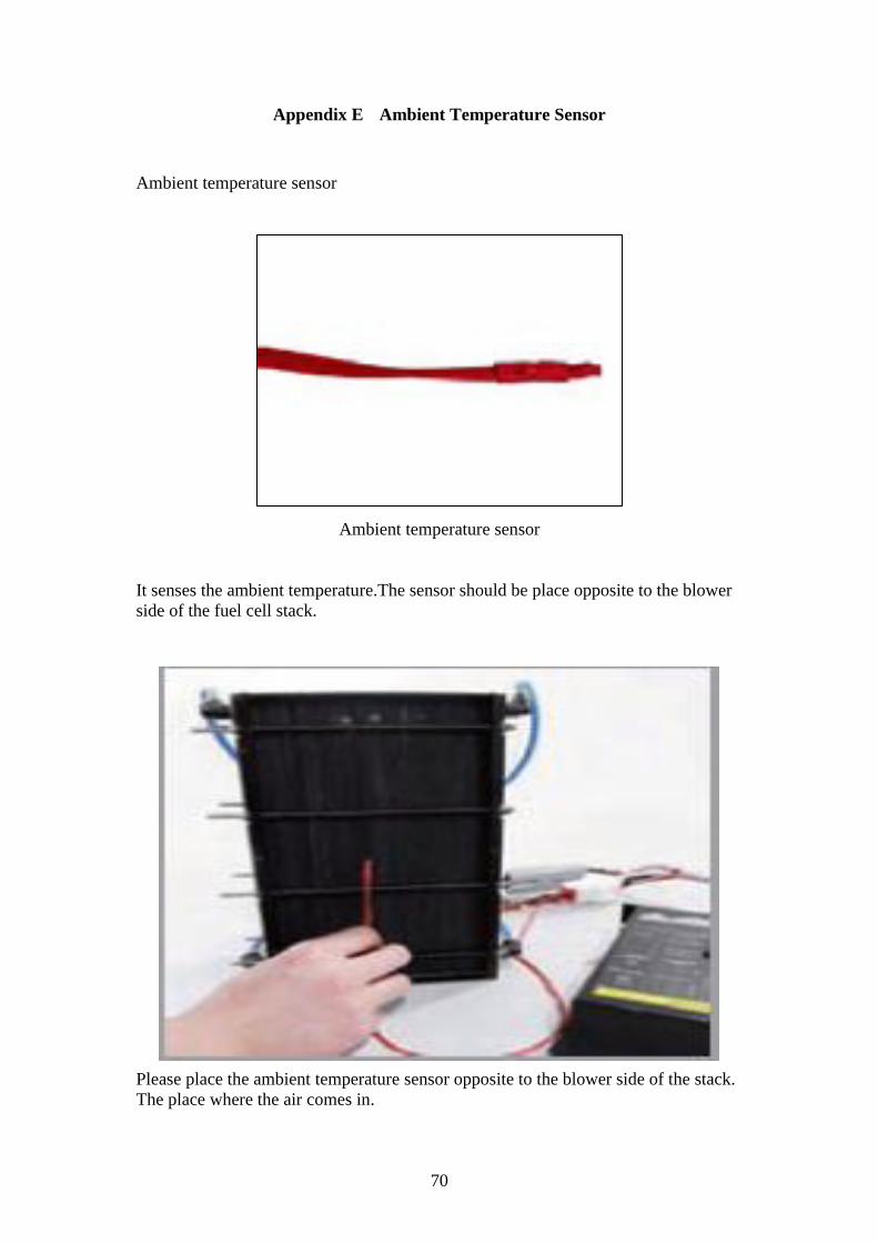
70
Appendix E Ambient Temperature Sensor
Ambient temperature sensor
Ambient temperature sensor
It senses the ambient temperature.The sensor should be place opposite to the blower
side of the fuel cell stack.
Please place the ambient temperature sensor opposite to the blower side of the stack.
The place where the air comes in.
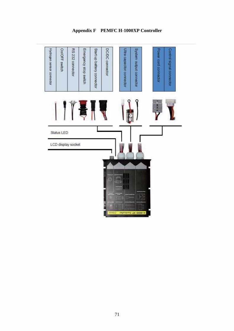
71
Appendix F PEMFC H-1000XP Controller