NCT Manual Revised May 2012
96
Údarás Um Shábháilteacht Ar Bhóithre Road Safety Authority NATIONAL CAR TEST (NCT) MANUAL 2012 Passenger Vehicles (Up to 8 Passengers) NATIONAL CAR TEST (NCT) MANUAL 2010
-
Upload
jmaguire1977 -
Category
Documents
-
view
141 -
download
2
description
NCT, testing, doe, ireland
Transcript of NCT Manual Revised May 2012
Údarás Um Shábháilteacht Ar BhóithreRoad Safety Authority
NATIONAL CAR TEST (NCT) MANUAL 2012Passenger Vehicles (Up to 8 Passengers)
Údarás Um Shábháilteacht Ar Bhóithre
Road Safety Authority
Páirc Ghnó Ghleann na Muaidhe, Cnoc an tSabhaircín, Bóthar Bhaile Átha Cliath, Béal an Átha, Co. Mhaigh Eo
Moy Valley Business Park, Primrose Hill, Dublin Road, Ballina, Co. Mayo
locall: 1890 50 60 80 fax: (096) 25252 email: [email protected] website: www.rsa.ie
Revision 2
BAILE ÁTHA CLIATH
ARNA FHOILSIÚ AG OIFIG AN tSOLÁTHAIR
Le ceannach díreach ón
OIFIG DHÍOLTA FOILSEACHÁN RIALTAIS
TEACH SUN ALLIANCE, SRÁID THEACH LAIGHEAN, BAILE ÁTHA CLIATH 2
nó tríd an bpost ó
FOILSEACHÁIN RIALTAIS, AN RANNÓG POST-TRÁCHTA
AONAD 20 PÁIRC MIONDÍOLA COIS LOCHA,CLÁR CHLAINNE MHUIRIS, CONTAE MHAIGH EO
(Teil: 01 – 6476834 nó 1890 213434; Fax 01 – 6476843 nó 094 - 9378964 )
nó trí aon díoltóir leabhar.
DUBLIN
PUBLISHED BY THE STATIONERY OFFICE
To be purchased directly from the
GOVERNMENT PUBLICATIONS SALE OFFICE
SUN ALLIANCE HOUSE, MOLESWORTH STREET, DUBLIN 2
or by mail order from
GOVERNMENT PUBLICATIONS, POSTAL TRADE SECTION
UNIT 20 LAKESIDE RETAIL PARK, CLAREMORRIS, CO. MAYO
(Tel: 01 – 6476834 or 1890 213434; Fax: 01 – 6476843 or 094 - 9378964)
or through any bookseller.
Working To Save Lives
NA
TIO
NA
L CA
R T
ES
T (N
CT
) MA
NU
AL 2
01
0 P
asse
ng
er V
eh
icles (U
p to
8 P
asse
ng
ers)

3
Road Safety AuthorityNational Car Test (NCT) Manual 2012
Covers Type M1 Vehicles
This Manual is not a legal document and must not be construed as such.
REVISIONS
This Manual may be revised and updated from time to time. A current version will always be available on the Road Safety Authority website: www.rsa.ie.
January 2012
Updated to implement changes arising from transposition of the latest EU directive on roadworthiness testing (Directive 2010/48/EU):
Item Numbers: 2, 3, 7, 21, 26, 27, 29, 32, 35, 37, 43, 46, 49, 54, 55, 57, 58 and 60
April 2012
Section 30 - Headlamp condition - changes to include test on HID lights
Introduction – person presenting the car for test must produce the required identification or the test certificate will not be issued
SAFETY
The methods of testing described in this Manual are intended to be carried out by trained and competent persons, working with appropriate supervision in suitable premises and with safe equipment and tools.
4
Reflectors 34 55
Bodywork 35 56
Tyre Condition 36 60
Tyre Specification 37 62
Tyre Tread 38 63
Wheels 39 64
Spare Wheel and Carrier 40 65
Brake Fluid 41 66
Chassis/Underbody 42 67
Steering Linkage 43 69
Wheel Bearings 44 71
Front Springs 45 72
Front Suspension 46 74
Brake Lines/Hoses 47 76
Shock Absorber Condition 48 77
Electrical System 49 78
Fuel System 50 79
Brake Wheel Units 51 81
Mechanical Brake Components 52 82
Brake Master Cylinder/Servo/Valves/Connections 53 83
Exhaust System/Noise 54 84
Rear Suspension 55 85
Rear Springs 56 86
Transmission & Drive Train 57 88
Rear Fog Lamp(s) 58 89
Reverse Lamp(s) 59 90
Malfunction Indicators 60 91
Registration Plate Lamps 61 92
Contents
Item N
o
Item N
o
Page
Page
Introduction 05
Methods of Testing and Reasons for Failure 07
Registration Plates 1 08
Exhaust Smoke (Diesel) 2 10
Exhaust CO/HC/Lambda 3 13
Service Brake Pedal 4 16
Service Brake Operation (Inspection inside the Vehicle) 5 17
Mechanical Brake Hand Actuator 6 18
Seats 7 19
Horn 8 20
Windscreen Wipers and Washers 9 21
Glass 10 22
Rear View Mirror(s) 11 27
Speedometer 12 28
Safety Belts 13 29
Steering Wheel Play 14 30
Doors/Locks/Anti-Theft Devices 15 31
Adaptations for Disabled Drivers 16 32
Front Wheel Side Slip 17 33
Rear Wheel Side Slip 18 34
Front Axle Suspension Performance 19 35
Rear Axle Suspension Performance 20 36
Service Brake Performance 21 37
Service Brake Imbalance 22 39
Parking Brake Performance 23 40
Parking Brake Imbalance 24 41
Towing Bracket/Coupling 25 42
Stop Lamps 26 43
Rear Lamps 27 44
Indicators/Tell Tales 28 45
Side Lamps (Front Position Lamps) 29 46
Headlamp Condition 30 47
Headlamp Aim 31 48
Auxiliary Lamp Condition & Position 32 52
Auxiliary Lamp Aim 33 54
5
N A T I O N A L C A R T E S T ( N C T ) M A N U A L 2 0 1 2
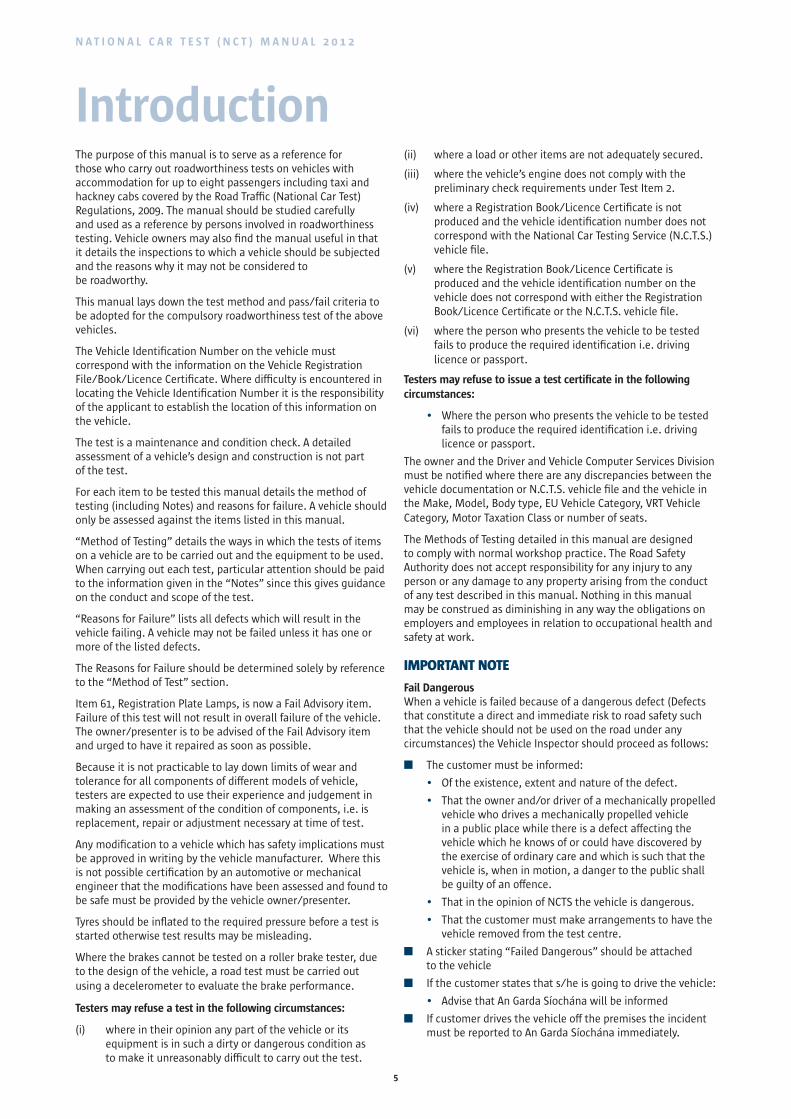
IntroductionThe purpose of this manual is to serve as a reference for those who carry out roadworthiness tests on vehicles with accommodation for up to eight passengers including taxi and hackney cabs covered by the Road Traffic (National Car Test) Regulations, 2009. The manual should be studied carefully and used as a reference by persons involved in roadworthiness testing. Vehicle owners may also find the manual useful in that it details the inspections to which a vehicle should be subjected and the reasons why it may not be considered to be roadworthy.
This manual lays down the test method and pass/fail criteria to be adopted for the compulsory roadworthiness test of the above vehicles.
The Vehicle Identification Number on the vehicle must correspond with the information on the Vehicle Registration File/Book/Licence Certificate. Where difficulty is encountered in locating the Vehicle Identification Number it is the responsibility of the applicant to establish the location of this information on the vehicle.
The test is a maintenance and condition check. A detailed assessment of a vehicle’s design and construction is not part of the test.
For each item to be tested this manual details the method of testing (including Notes) and reasons for failure. A vehicle should only be assessed against the items listed in this manual.
“Method of Testing” details the ways in which the tests of items on a vehicle are to be carried out and the equipment to be used. When carrying out each test, particular attention should be paid to the information given in the “Notes” since this gives guidance on the conduct and scope of the test.
“Reasons for Failure” lists all defects which will result in the vehicle failing. A vehicle may not be failed unless it has one or more of the listed defects.
The Reasons for Failure should be determined solely by reference to the “Method of Test” section.
Item 61, Registration Plate Lamps, is now a Fail Advisory item. Failure of this test will not result in overall failure of the vehicle. The owner/presenter is to be advised of the Fail Advisory item and urged to have it repaired as soon as possible.
Because it is not practicable to lay down limits of wear and tolerance for all components of different models of vehicle, testers are expected to use their experience and judgement in making an assessment of the condition of components, i.e. is replacement, repair or adjustment necessary at time of test.
Any modification to a vehicle which has safety implications must be approved in writing by the vehicle manufacturer. Where this is not possible certification by an automotive or mechanical engineer that the modifications have been assessed and found to be safe must be provided by the vehicle owner/presenter.
Tyres should be inflated to the required pressure before a test is started otherwise test results may be misleading.
Where the brakes cannot be tested on a roller brake tester, due to the design of the vehicle, a road test must be carried out using a decelerometer to evaluate the brake performance.
Testers may refuse a test in the following circumstances:
(i) where in their opinion any part of the vehicle or its equipment is in such a dirty or dangerous condition as to make it unreasonably difficult to carry out the test.
(ii) where a load or other items are not adequately secured.
(iii) where the vehicle’s engine does not comply with the preliminary check requirements under Test Item 2.
(iv) where a Registration Book/Licence Certificate is not produced and the vehicle identification number does not correspond with the National Car Testing Service (N.C.T.S.) vehicle file.
(v) where the Registration Book/Licence Certificate is produced and the vehicle identification number on the vehicle does not correspond with either the Registration Book/Licence Certificate or the N.C.T.S. vehicle file.
(vi) where the person who presents the vehicle to be tested fails to produce the required identification i.e. driving licence or passport.
Testers may refuse to issue a test certificate in the following circumstances:
• Where the person who presents the vehicle to be tested fails to produce the required identification i.e. driving licence or passport.
The owner and the Driver and Vehicle Computer Services Division must be notified where there are any discrepancies between the vehicle documentation or N.C.T.S. vehicle file and the vehicle in the Make, Model, Body type, EU Vehicle Category, VRT Vehicle Category, Motor Taxation Class or number of seats.
The Methods of Testing detailed in this manual are designed to comply with normal workshop practice. The Road Safety Authority does not accept responsibility for any injury to any person or any damage to any property arising from the conduct of any test described in this manual. Nothing in this manual may be construed as diminishing in any way the obligations on employers and employees in relation to occupational health and safety at work.
IMPORTANT NOTE
Fail Dangerous When a vehicle is failed because of a dangerous defect (Defects that constitute a direct and immediate risk to road safety such that the vehicle should not be used on the road under any circumstances) the Vehicle Inspector should proceed as follows:
n The customer must be informed:
• Of the existence, extent and nature of the defect.
• That the owner and/or driver of a mechanically propelled vehicle who drives a mechanically propelled vehicle in a public place while there is a defect affecting the vehicle which he knows of or could have discovered by the exercise of ordinary care and which is such that the vehicle is, when in motion, a danger to the public shall be guilty of an offence.
• That in the opinion of NCTS the vehicle is dangerous.
• That the customer must make arrangements to have the vehicle removed from the test centre.
n A sticker stating “Failed Dangerous” should be attached to the vehicle
n If the customer states that s/he is going to drive the vehicle:
• Advise that An Garda Síochána will be informed
n If customer drives the vehicle off the premises the incident must be reported to An Garda Síochána immediately.

6
N A T I O N A L C A R T E S T ( N C T ) M A N U A L 2 0 1 2
7
N A T I O N A L C A R T E S T ( N C T ) M A N U A L 2 0 1 2
Methods of Testing andReasons for Failure
8
N A T I O N A L C A R T E S T ( N C T ) M A N U A L 2 0 1 2
REGISTRATION PLATES1
Method of Testing
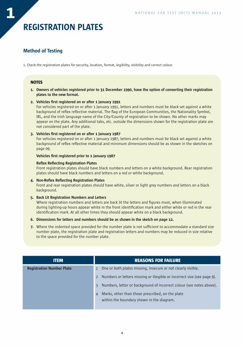
1. Check the registration plates for security, location, format, legibility, visibility and correct colour.
NOTES
1. Owners of vehicles registered prior to 31 December 1990, have the option of converting their registration plates to the new format.
2. Vehicles first registered on or after 1 January 1991 For vehicles registered on or after 1 January 1991, letters and numbers must be black set against a white background of reflex reflective material. The flag of the European Communities, the Nationality Symbol, IRL, and the Irish language name of the City/County of registration to be shown. No other marks may appear on the plate. Any additional tabs, etc. outside the dimensions shown for the registration plate are not considered part of the plate.
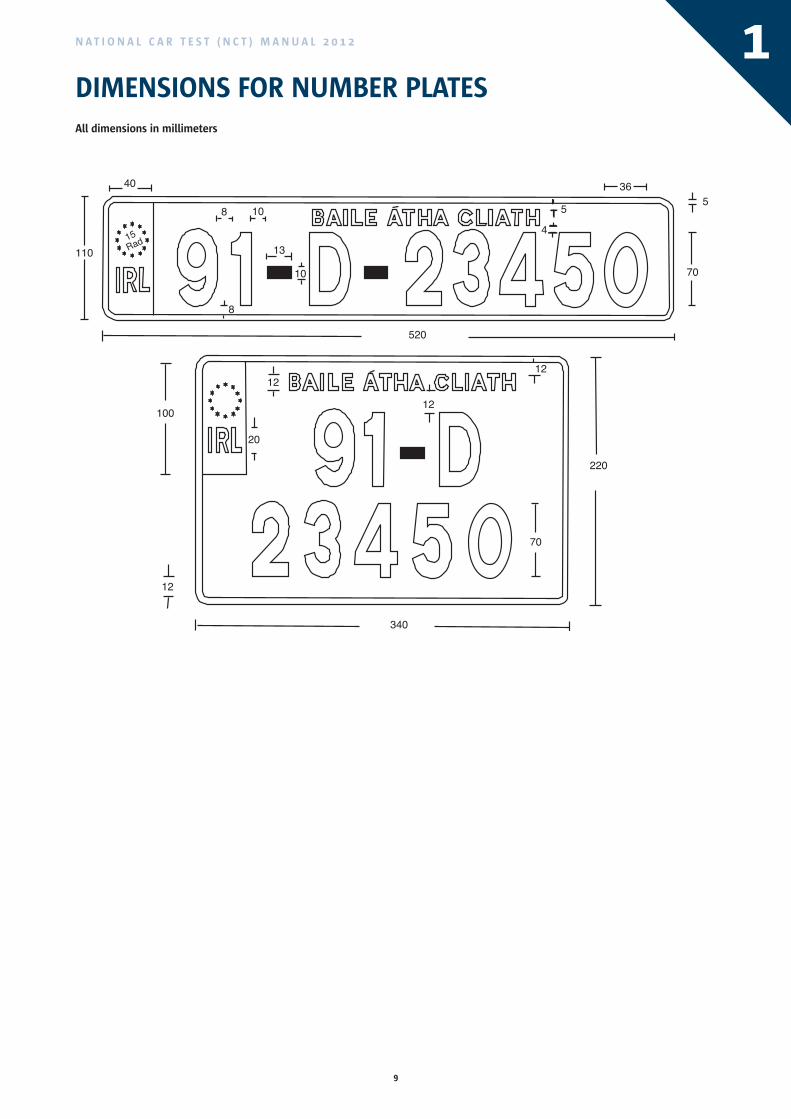
3. Vehicles first registered on or after 1 January 1987 For vehicles registered on or after 1 January 1987, letters and numbers must be black set against a white background of reflex reflective material and minimum dimensions should be as shown in the sketches on page 09.
Vehicles first registered prior to 1 January 1987
Reflex Reflecting Registration Plates Front registration plates should have black numbers and letters on a white background. Rear registration plates should have black numbers and letters on a red or white background.
4. Non-Reflex Reflecting Registration Plates Front and rear registration plates should have white, silver or light grey numbers and letters on a black background.
5. Back Lit Registration Numbers and Letters Where registration numbers and letters are back lit the letters and figures must, when illuminated during lighting-up hours appear white in the front identification mark and either white or red in the rear identification mark. At all other times they should appear white on a black background.
6. Dimensions for letters and numbers should be as shown in the sketch on page 12.
7. Where the indented space provided for the number plate is not sufficient to accommodate a standard size number plate, the registration plate and registration letters and numbers may be reduced in size relative to the space provided for the number plate.
ITEM REASONS FOR FAILURE
Registration Number Plate 1 One or both plates missing, insecure or not clearly visible.
2 Numbers or letters missing or illegible or incorrect size (see page 9).
3 Numbers, letter or background of incorrect colour (see notes above).
4 Marks, other than those prescribed, on the plate
within the boundary shown in the diagram.
9
N A T I O N A L C A R T E S T ( N C T ) M A N U A L 2 0 1 2
DIMENSIONS FOR NUMBER PLATES1
All dimensions in millimeters
100
12
20
12
12
220
70
340
12
110
8
13
10
520
70
55
4108
40
15Rad
36
10
N A T I O N A L C A R T E S T ( N C T ) M A N U A L 2 0 1 2
EXHAUST SMOKE (DIESEL)
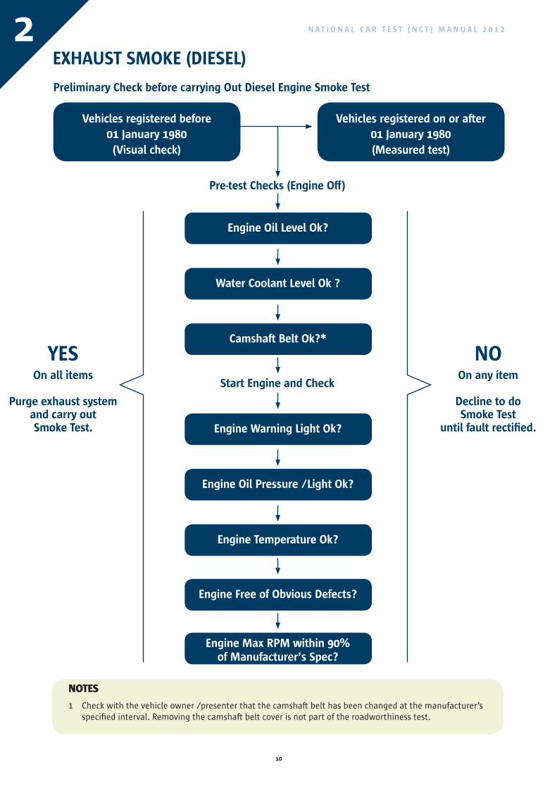
Preliminary Check before carrying Out Diesel Engine Smoke Test
Vehicles registered before01 January 1980(Visual check)
Engine Oil Level Ok?
Engine Warning Light Ok?
Water Coolant Level Ok ?
Engine Oil Pressure /Light Ok?
Camshaft Belt Ok?*
Engine Temperature Ok?
Engine Free of Obvious Defects?
Engine Max RPM within 90%of Manufacturer’s Spec?
Pre-test Checks (Engine Off)
Start Engine and Check
NOOn any item
Decline to do Smoke Test
until fault rectified.
YESOn all items
Purge exhaust system
and carry out Smoke Test.
Vehicles registered on or after01 January 1980(Measured test)
NOTES
1 Check with the vehicle owner /presenter that the camshaft belt has been changed at the manufacturer’s specified interval. Removing the camshaft belt cover is not part of the roadworthiness test.
2
11
N A T I O N A L C A R T E S T ( N C T ) M A N U A L 2 0 1 2
EXHAUST SMOKE (DIESEL)
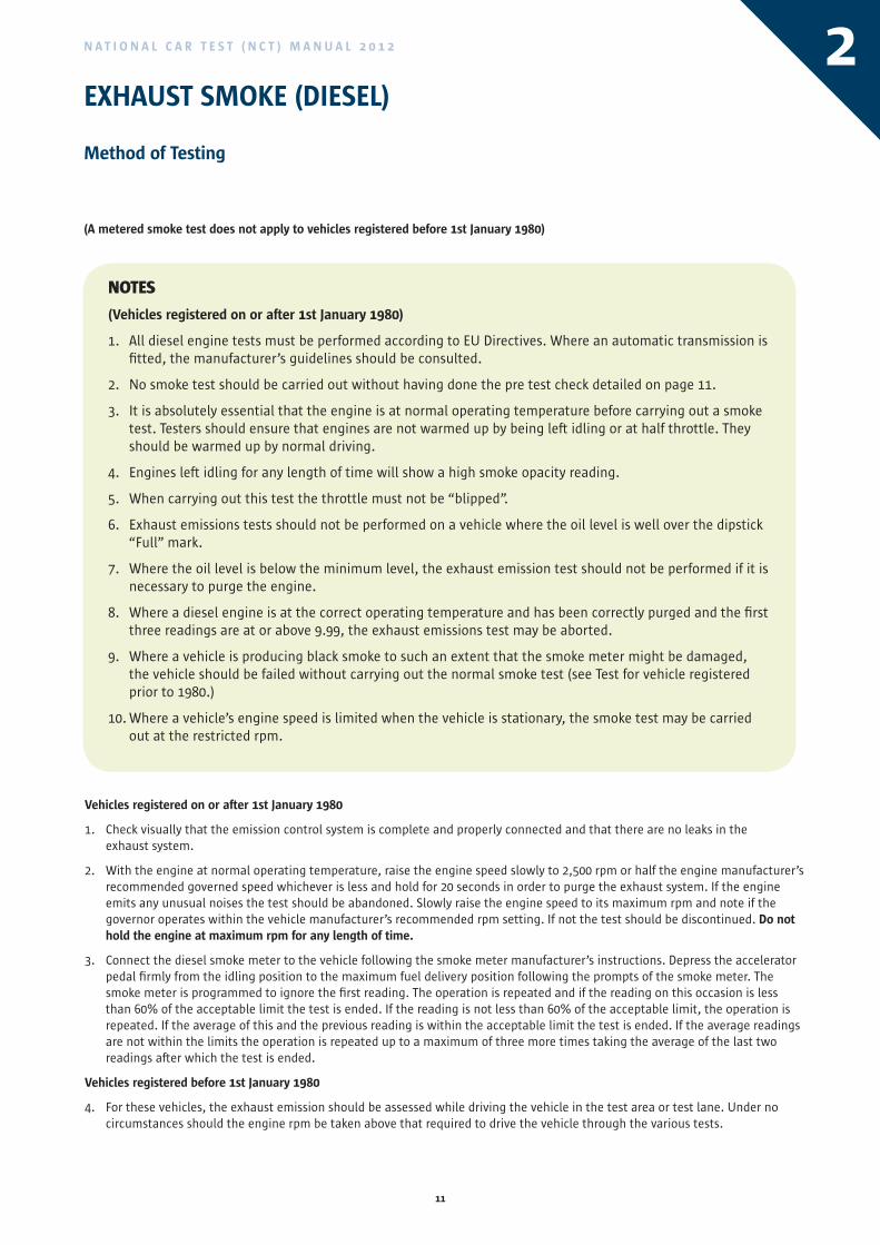
Method of Testing
(A metered smoke test does not apply to vehicles registered before 1st January 1980)
NOTES
(Vehicles registered on or after 1st January 1980)
1. All diesel engine tests must be performed according to EU Directives. Where an automatic transmission is fitted, the manufacturer’s guidelines should be consulted.
2. No smoke test should be carried out without having done the pre test check detailed on page 11.
3. It is absolutely essential that the engine is at normal operating temperature before carrying out a smoke test. Testers should ensure that engines are not warmed up by being left idling or at half throttle. They should be warmed up by normal driving.
4. Engines left idling for any length of time will show a high smoke opacity reading.
5. When carrying out this test the throttle must not be “blipped”.
6. Exhaust emissions tests should not be performed on a vehicle where the oil level is well over the dipstick “Full” mark.
7. Where the oil level is below the minimum level, the exhaust emission test should not be performed if it is necessary to purge the engine.
8. Where a diesel engine is at the correct operating temperature and has been correctly purged and the first three readings are at or above 9.99, the exhaust emissions test may be aborted.
9. Where a vehicle is producing black smoke to such an extent that the smoke meter might be damaged, the vehicle should be failed without carrying out the normal smoke test (see Test for vehicle registered prior to 1980.)
10. Where a vehicle’s engine speed is limited when the vehicle is stationary, the smoke test may be carried out at the restricted rpm.
Vehicles registered on or after 1st January 1980
1. Check visually that the emission control system is complete and properly connected and that there are no leaks in the exhaust system.
2. With the engine at normal operating temperature, raise the engine speed slowly to 2,500 rpm or half the engine manufacturer’s recommended governed speed whichever is less and hold for 20 seconds in order to purge the exhaust system. If the engine emits any unusual noises the test should be abandoned. Slowly raise the engine speed to its maximum rpm and note if the governor operates within the vehicle manufacturer’s recommended rpm setting. If not the test should be discontinued. Do not hold the engine at maximum rpm for any length of time.
3. Connect the diesel smoke meter to the vehicle following the smoke meter manufacturer’s instructions. Depress the accelerator pedal firmly from the idling position to the maximum fuel delivery position following the prompts of the smoke meter. The smoke meter is programmed to ignore the first reading. The operation is repeated and if the reading on this occasion is less than 60% of the acceptable limit the test is ended. If the reading is not less than 60% of the acceptable limit, the operation is repeated. If the average of this and the previous reading is within the acceptable limit the test is ended. If the average readings are not within the limits the operation is repeated up to a maximum of three more times taking the average of the last two readings after which the test is ended.
Vehicles registered before 1st January 1980
4. For these vehicles, the exhaust emission should be assessed while driving the vehicle in the test area or test lane. Under no circumstances should the engine rpm be taken above that required to drive the vehicle through the various tests.
2
NOOn any item
Decline to do Smoke Test
until fault rectified.
12
N A T I O N A L C A R T E S T ( N C T ) M A N U A L 2 0 1 2
EXHAUST SMOKE (DIESEL)
ITEM REASONS FOR FAILURE
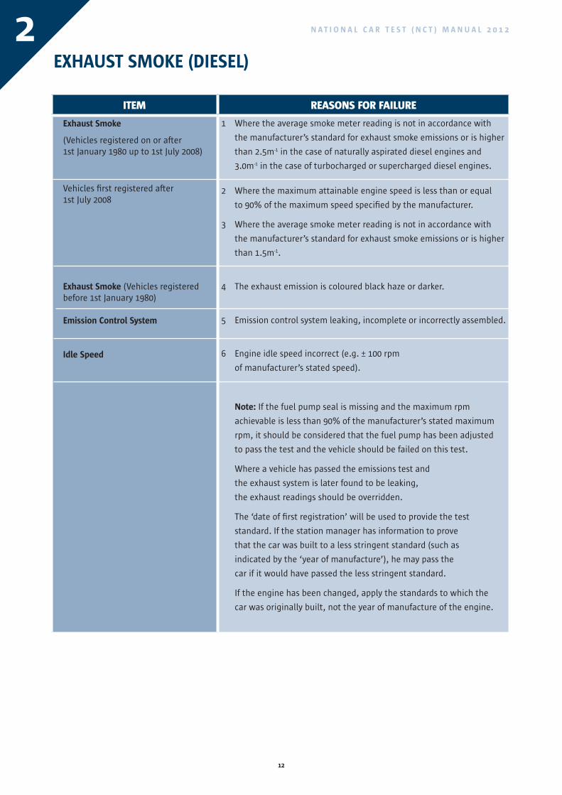
Exhaust Smoke
(Vehicles registered on or after 1st January 1980 up to 1st July 2008)
Vehicles first registered after 1st July 2008
Exhaust Smoke (Vehicles registered before 1st January 1980)
Emission Control System
Idle Speed
1 Where the average smoke meter reading is not in accordance with
the manufacturer’s standard for exhaust smoke emissions or is higher
than 2.5m-1 in the case of naturally aspirated diesel engines and
3.0m-1 in the case of turbocharged or supercharged diesel engines.
2 Where the maximum attainable engine speed is less than or equal
to 90% of the maximum speed specified by the manufacturer.
3 Where the average smoke meter reading is not in accordance with
the manufacturer’s standard for exhaust smoke emissions or is higher
than 1.5m-1.
4 The exhaust emission is coloured black haze or darker.
5 Emission control system leaking, incomplete or incorrectly assembled.
6 Engine idle speed incorrect (e.g. ± 100 rpm
of manufacturer’s stated speed).
Note: If the fuel pump seal is missing and the maximum rpm
achievable is less than 90% of the manufacturer’s stated maximum
rpm, it should be considered that the fuel pump has been adjusted
to pass the test and the vehicle should be failed on this test.
Where a vehicle has passed the emissions test and
the exhaust system is later found to be leaking,
the exhaust readings should be overridden.
The ‘date of first registration’ will be used to provide the test
standard. If the station manager has information to prove
that the car was built to a less stringent standard (such as
indicated by the ‘year of manufacture’), he may pass the
car if it would have passed the less stringent standard.
If the engine has been changed, apply the standards to which the
car was originally built, not the year of manufacture of the engine.
2
13
N A T I O N A L C A R T E S T ( N C T ) M A N U A L 2 0 1 2
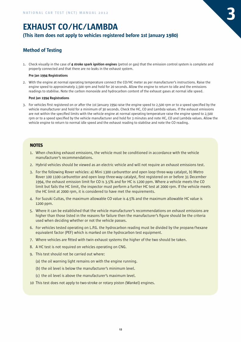
EXHAUST CO/HC/LAMBDA (This item does not apply to vehicles registered before 1st January 1980)
Method of Testing
1. Check visually in the case of 4 stroke spark ignition engines (petrol or gas) that the emission control system is complete and properly connected and that there are no leaks in the exhaust system.
Pre Jan 1994 Registrations
2. With the engine at normal operating temperature connect the CO/HC meter as per manufacturer’s instructions. Raise the engine speed to approximately 2,500 rpm and hold for 20 seconds. Allow the engine to return to idle and the emissions readings to stabilise. Note the carbon monoxide and hydrocarbon content of the exhaust gases at normal idle speed.
Post Jan 1994 Registrations
3. For vehicles first registered on or after the 1st January 1994 raise the engine speed to 2,500 rpm or to a speed specified by the vehicle manufacturer and hold for a minimum of 30 seconds. Check the HC, CO and Lambda values. If the exhaust emissions are not within the specified limits with the vehicle engine at normal operating temperature raise the engine speed to 2,500 rpm or to a speed specified by the vehicle manufacturer and hold for 3 minutes and note HC, CO and Lambda values. Allow the vehicle engine to return to normal idle speed and the exhaust reading to stabilise and note the CO reading.
NOTES
1. When checking exhaust emissions, the vehicle must be conditioned in accordance with the vehicle manufacturer’s recommendations.
2. Hybrid vehicles should be viewed as an electric vehicle and will not require an exhaust emissions test.
3. For the following Rover vehicles: a) Mini 1300 carburettor and open loop three-way catalyst, b) Metro Rover 100 1100 carburettor and open loop three-way catalyst, first registered on or before 31 December 1994, the exhaust emission limit for CO is 3.5% and for HC is 1200 ppm. Where a vehicle meets the CO limit but fails the HC limit, the inspector must perform a further HC test at 2000 rpm. If the vehicle meets the HC limit at 2000 rpm, it is considered to have met the requirements.
4. For Suzuki Cultas, the maximum allowable CO value is 4.5% and the maximum allowable HC value is 1200 ppm.
5. Where it can be established that the vehicle manufacturer’s recommendations on exhaust emissions are higher than those listed in the reasons for failure then the manufacturer’s figure should be the criteria used when deciding whether or not the vehicle passes.
6. For vehicles tested operating on L.P.G. the hydrocarbon reading must be divided by the propane/hexane equivalent factor (PEF) which is marked on the hydrocarbon test equipment.
7. Where vehicles are fitted with twin exhaust systems the higher of the two should be taken.
8. A HC test is not required on vehicles operating on CNG.
9. This test should not be carried out where:
(a) the oil warning light remains on with the engine running.
(b) the oil level is below the manufacturer’s minimum level.
(c) the oil level is above the manufacturer’s maximum level.
10 This test does not apply to two-stroke or rotary piston (Wankel) engines.
3
14
N A T I O N A L C A R T E S T ( N C T ) M A N U A L 2 0 1 2
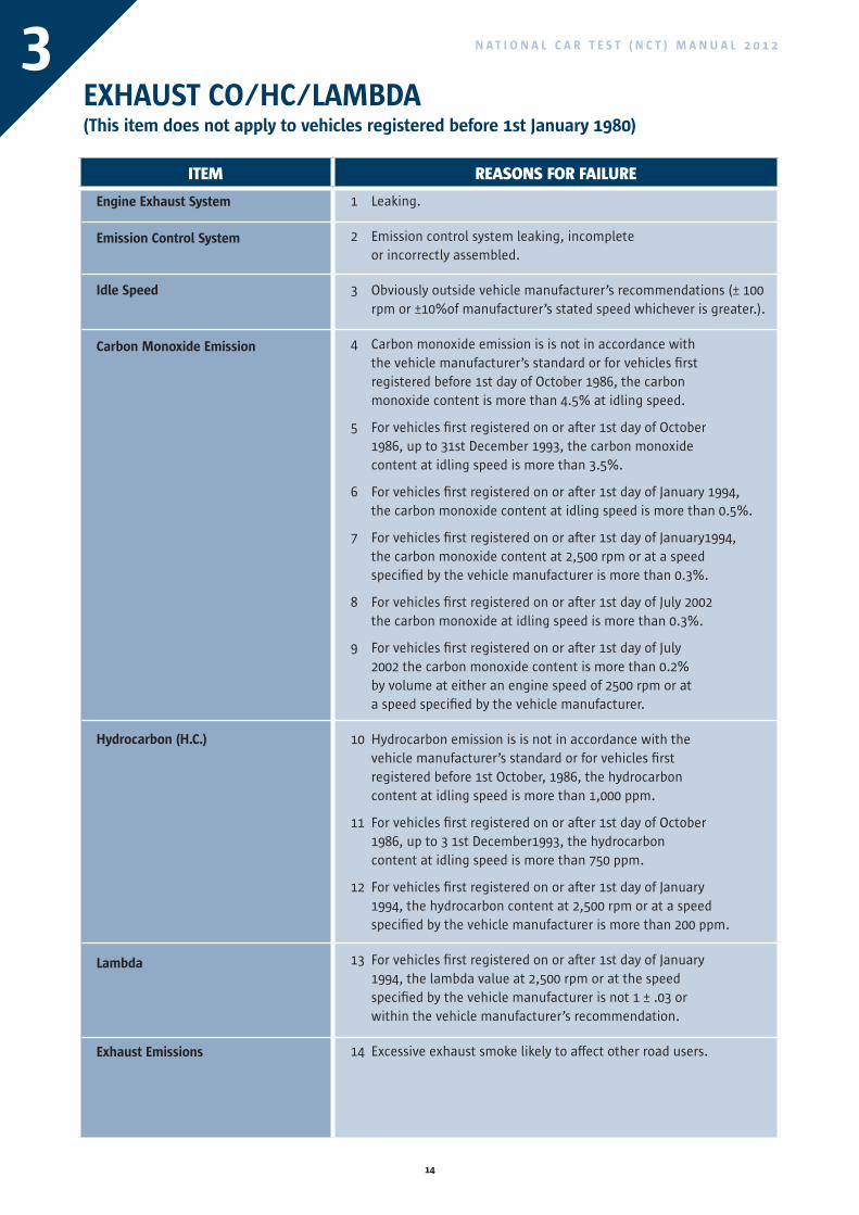
EXHAUST CO/HC/LAMBDA (This item does not apply to vehicles registered before 1st January 1980)
ITEM REASONS FOR FAILURE
Engine Exhaust System
Emission Control System
Idle Speed
Carbon Monoxide Emission
Hydrocarbon (H.C.)
Lambda
Exhaust Emissions
1 Leaking.
2 Emission control system leaking, incomplete or incorrectly assembled.
3 Obviously outside vehicle manufacturer’s recommendations (± 100 rpm or ±10%of manufacturer’s stated speed whichever is greater.).
4 Carbon monoxide emission is is not in accordance with the vehicle manufacturer’s standard or for vehicles first registered before 1st day of October 1986, the carbon monoxide content is more than 4.5% at idling speed.
5 For vehicles first registered on or after 1st day of October 1986, up to 31st December 1993, the carbon monoxide content at idling speed is more than 3.5%.
6 For vehicles first registered on or after 1st day of January 1994, the carbon monoxide content at idling speed is more than 0.5%.
7 For vehicles first registered on or after 1st day of January1994, the carbon monoxide content at 2,500 rpm or at a speed specified by the vehicle manufacturer is more than 0.3%.
8 For vehicles first registered on or after 1st day of July 2002 the carbon monoxide at idling speed is more than 0.3%.
9 For vehicles first registered on or after 1st day of July 2002 the carbon monoxide content is more than 0.2% by volume at either an engine speed of 2500 rpm or at a speed specified by the vehicle manufacturer.
10 Hydrocarbon emission is is not in accordance with the vehicle manufacturer’s standard or for vehicles first registered before 1st October, 1986, the hydrocarbon content at idling speed is more than 1,000 ppm.
11 For vehicles first registered on or after 1st day of October 1986, up to 3 1st December1993, the hydrocarbon content at idling speed is more than 750 ppm.
12 For vehicles first registered on or after 1st day of January 1994, the hydrocarbon content at 2,500 rpm or at a speed specified by the vehicle manufacturer is more than 200 ppm.
13 For vehicles first registered on or after 1st day of January 1994, the lambda value at 2,500 rpm or at the speed specified by the vehicle manufacturer is not 1 ± .03 or within the vehicle manufacturer’s recommendation.
14 Excessive exhaust smoke likely to affect other road users.
3
15
N A T I O N A L C A R T E S T ( N C T ) M A N U A L 2 0 1 2 3EXHAUST CO/HC/LAMBDA
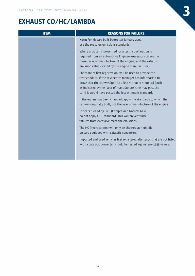
ITEM REASONS FOR FAILURE
Note: For kit cars built before 1st January 2000,
use the pre-1994 emissions standards.
Where a kit car is presented for a test, a declaration is
required from an automotive Engineer/Assessor stating the
make, year of manufacture of the engine, and the exhaust
emission values stated by the engine manufacturer.
The ‘date of first registration’ will be used to provide the
test standard. If the test centre manager has information to
prove that the car was built to a less stringent standard (such
as indicated by the ‘year of manufacture’), he may pass the
car if it would have passed the less stringent standard.
If the engine has been changed, apply the standards to which the
car was originally built, not the year of manufacture of the engine.
For cars fuelled by CNG (Compressed Natural Gas)
do not apply a HC standard. This will prevent false
failures from excessive methane emissions.
The HC (hydrocarbon) will only be checked at high idle
on cars equipped with catalytic converters.
Imported and used vehicles first registered after 1994 that are not fitted
with a catalytic converter should be tested against pre-1995 values.
EXHAUST CO/HC/LAMBDA (This item does not apply to vehicles registered before 1st January 1980)
16
N A T I O N A L C A R T E S T ( N C T ) M A N U A L 2 0 1 2
SERVICE BRAKE PEDAL
Method of Testing
SEE NOTE (1) BELOW
1. Check the anti-slip provisions on the pedal pad.
2. Examine the condition of the pedal.
3. Check the fixing of the pedal pad to the pedal and the fixing of the pedal to the operating lever.
4. Move the pedal from side to side and examine the condition of the pedal pivot bearing/bush.
5. Depress the pedal to check for fouling on parts of the vehicle.
NOTES
1. Before carrying out this inspection, chock the road wheels.
2. Brake pedals should not be rejected for not having a pedal rubber if they were not designed to have one.
ITEM REASONS FOR FAILURE
Service Brake Pedal Anti-Slip Provision
Service Brake Pedal Mounting
Service Brake Pedal Travel
1 Missing, loose or worn to the extent that it is no longer effective.
2 Insecure, badly corroded or worn to the extent that the pedal can be moved from side to side.
3 Excessive wear in brake pedal mounting bush.
4 Pedal travel is obstructed.
4
17
N A T I O N A L C A R T E S T ( N C T ) M A N U A L 2 0 1 2 5SERVICE BRAKE OPERATION(Inspection inside the Vehicle)
Method of Testing
1. For hydraulic systems, fully depress the pedal and keep it depressed under a steady pressure. Note whether the pedal tends to creep down.
2. For hydraulic systems release the handbrake, depress the pedal and note the extent of travel of the brake pedal and whether there is sponginess.
3. On some vehicles the action of the brakes is assisted by vacuum from the engine. In such cases deplete the vacuum by applying the service brake a number of times with the engine switched off. Fully apply the service brake, start the engine and note whether the pedal can be felt to dip.
4. If the vehicle is fitted with a brake anti-lock system, check the warning lamp.
ITEM REASONS FOR FAILURE
Service Brake Operation 1 In hydraulic systems, pedal tends to creep down, or is felt to be spongy when held depressed.
2 Travel in the brake pedal indicates air in the brake system or brakes in need of adjustment.
3 In systems assisted by vacuum from engine, with the pedal depressed and the engine started, no dip is felt in brake pedal.
NOTES
1. The check procedure on Anti-Lock Brake Systems will vary according to the type of system fitted. The manufacturer’s handbook should be consulted for the correct check procedure.
ITEM REASONS FOR FAILURE
Service Brake Pedal Anti-Slip Provision
Service Brake Pedal Mounting
Service Brake Pedal Travel
1 Missing, loose or worn to the extent that it is no longer effective.
2 Insecure, badly corroded or worn to the extent that the pedal can be moved from side to side.
3 Excessive wear in brake pedal mounting bush.
4 Pedal travel is obstructed.
18
N A T I O N A L C A R T E S T ( N C T ) M A N U A L 2 0 1 2
Method of Testing
SEE NOTES BELOW
1. Examine the condition of the brake lever and its position.
2. With the brake lever in the “off” position:
(a) note the amount of side play in the lever pivot by moving the lever from side to side.
(b) check the condition of the ratchet and pawl mechanism pivots.
(c) check the safety guard.
3. Apply the brake lever slowly and check the effective operation of the pawl mechanism by listening for definite and regular clicks as the pawl moves over the ratchet teeth.
4. When the brake is fully applied:
(a) knock the top and each side of the lever by hand and check that the lever is held in the ‘on’ position.
(b) check that the lever is not at the end of its permitted travel and that there is no fouling of adjacent parts.
ITEM REASONS FOR FAILURE
Lever/Lever Mounting
Ratchet and Pawl Mechanism (where fitted)
1 Missing, fractured, badly worn or corroded, insecure or mounting unsatisfactory.
2 Travel is excessive or movement is obstructed.
3 Missing, insecure, damaged or sticking.
4 Definite and regular clicks are not heard, indicating worn mechanism.
MECHANICAL BRAKE HAND LEVER(where fitted)
NOTES
1. Before carrying out this inspection, chock the road wheels.
2. In some cases it is not possible to check these items completely from inside the vehicle, but only to obtain an indication of their condition. If a defect is suspected which cannot be verified from inside the vehicle the inspection must be continued from a position underneath the vehicle.
6
19
N A T I O N A L C A R T E S T ( N C T ) M A N U A L 2 0 1 2 7
ITEM REASONS FOR FAILURE
Seats
Driver’s Seat
1 Loose on runners or insecurely mounted.
2 Collapsed or framework damaged.
3 Seat so damaged that driver’s support is impaired.
4 Driver’s seat adjustment mechanism not functioning correctly.
Note: A seat should fail when it is so loose that detachment from the runners or sliding backwards or forwards is likely.
The driver’s seat should be failed where the seat support foam cannot be contained, e.g. keeps falling out. This does not mean the seat fails if the upholstery is torn or worn. A seat cover is an acceptable means of containing the foam.
SEATS
Method of Testing
1. Examine all seats and seat mountings for security and condition.
2. Note any movement of the seat relative to the vehicle body and the condition of the seat back and seat cushion.
NOTES
1. Seats include child seats or child restraint systems
ITEM REASONS FOR FAILURE
Lever/Lever Mounting
Ratchet and Pawl Mechanism (where fitted)
1 Missing, fractured, badly worn or corroded, insecure or mounting unsatisfactory.
2 Travel is excessive or movement is obstructed.
3 Missing, insecure, damaged or sticking.
4 Definite and regular clicks are not heard, indicating worn mechanism.
20
N A T I O N A L C A R T E S T ( N C T ) M A N U A L 2 0 1 2
ITEM REASONS FOR FAILURE
Horn 1 Control insecure.
2 Horn insecurely mounted.
3 Not working correctly.
4 Not working or not fitted.
HORN
Method of Testing
1. Check the security of the horn and horn control.
2. Operate the horn control and note that the horn sounds correctly.
8
21
N A T I O N A L C A R T E S T ( N C T ) M A N U A L 2 0 1 2 9
ITEM REASONS FOR FAILURE
Wiper Arms and Blades
Speed of Wipers
Wiper Control
Wiper Linkage
Washers (if fitted)
1 Missing.
2 Not cleaning windscreen effectively.
3 Wiped area less than sufficient to give the driver an adequate view.
4 Not operating normally.
5 Insecurely mounted.
6 Not working, defective or missing.
7 Broken, excessively worn or insecure.
8 Not working or incorrectly aimed.
Note: Where no washer is fitted or there is no fluid in the washer reservoir, check the function of the wipers and visually for defects on the blade that would fail effectiveness (reason 2).
WINDSCREEN WIPERS AND WASHERS
Method of Testing
1. Switch on the windscreen wipers and washers and check for operation and security and that the wipers move at an appropriate speed over an arc of the windscreen glass which is sufficient to give the driver an adequate view.
2. Check the wiper control.
3. Examine the condition of the wiper arms and blades. Check that the springs are not weak or broken.
4. Check wiper linkage for wear.
5. Check that the windscreen washer(s) function satisfactorily.
NOTES
1. Washers will be considered as being fitted if there is any part of a washer system fitted.
2. This test only applies to front windscreens.
ITEM REASONS FOR FAILURE
Horn 1 Control insecure.
2 Horn insecurely mounted.
3 Not working correctly.
4 Not working or not fitted.
22
N A T I O N A L C A R T E S T ( N C T ) M A N U A L 2 0 1 2
GLASS
Method of Testing
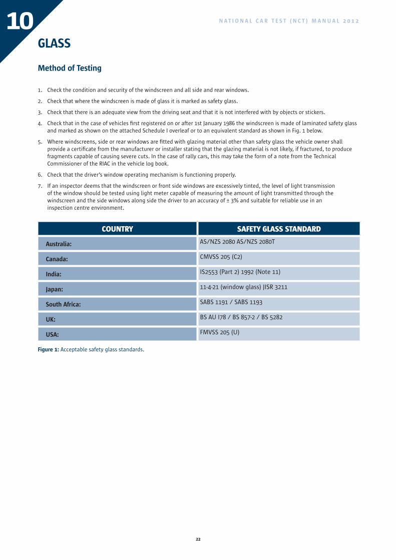
1. Check the condition and security of the windscreen and all side and rear windows.
2. Check that where the windscreen is made of glass it is marked as safety glass.
3. Check that there is an adequate view from the driving seat and that it is not interfered with by objects or stickers.
4. Check that in the case of vehicles first registered on or after 1st January 1986 the windscreen is made of laminated safety glass and marked as shown on the attached Schedule I overleaf or to an equivalent standard as shown in Fig. 1 below.
5. Where windscreens, side or rear windows are fitted with glazing material other than safety glass the vehicle owner shall provide a certificate from the manufacturer or installer stating that the glazing material is not likely, if fractured, to produce fragments capable of causing severe cuts. In the case of rally cars, this may take the form of a note from the Technical Commissioner of the RIAC in the vehicle log book.
6. Check that the driver’s window operating mechanism is functioning properly.
7. If an inspector deems that the windscreen or front side windows are excessively tinted, the level of light transmission of the window should be tested using light meter capable of measuring the amount of light transmitted through the windscreen and the side windows along side the driver to an accuracy of ± 3% and suitable for reliable use in an inspection centre environment.
COUNTRY SAFETY GLASS STANDARD
Australia: AS/NZS 2080 AS/NZS 2080T
Canada: CMVSS 205 (C2)
India: IS2553 (Part 2) 1992 (Note 11)
Japan: 11-4-21 (window glass) JISR 3211
South Africa: SABS 1191 / SABS 1193
UK: BS AU I78 / BS 857-2 / BS 5282
USA: FMVSS 205 (U)
Figure 1: Acceptable safety glass standards.
10
23
N A T I O N A L C A R T E S T ( N C T ) M A N U A L 2 0 1 2 10GLASS
NOTES
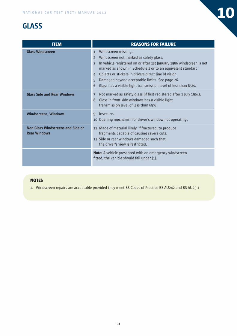
1. Windscreen repairs are acceptable provided they meet BS Codes of Practice BS AU242 and BS AU25 1
ITEM REASONS FOR FAILURE
Glass Windscreen
Glass Side and Rear Windows
Windscreens, Windows
Non Glass Windscreens and Side or Rear Windows
1 Windscreen missing.
2 Windscreen not marked as safety glass.
3 In vehicle registered on or after 1st January 1986 windscreen is not marked as shown in Schedule 1 or to an equivalent standard.
4 Objects or stickers in drivers direct line of vision.
5 Damaged beyond acceptable limits. See page 26.
6 Glass has a visible light transmission level of less than 65%.
7 Not marked as safety glass (if first registered after 1 July 1964).
8 Glass in front side windows has a visible light transmission level of less than 65%.
9 Insecure.
10 Opening mechanism of driver’s window not operating.
11 Made of material likely, if fractured, to produce fragments capable of causing severe cuts.
12 Side or rear windows damaged such that the driver’s view is restricted.
Note: A vehicle presented with an emergency windscreen fitted, the vehicle should fail under (1).
COUNTRY SAFETY GLASS STANDARD
Australia: AS/NZS 2080 AS/NZS 2080T
Canada: CMVSS 205 (C2)
India: IS2553 (Part 2) 1992 (Note 11)
Japan: 11-4-21 (window glass) JISR 3211
South Africa: SABS 1191 / SABS 1193
UK: BS AU I78 / BS 857-2 / BS 5282
USA: FMVSS 205 (U)
24
N A T I O N A L C A R T E S T ( N C T ) M A N U A L 2 0 1 2
GLASSSchedule 1
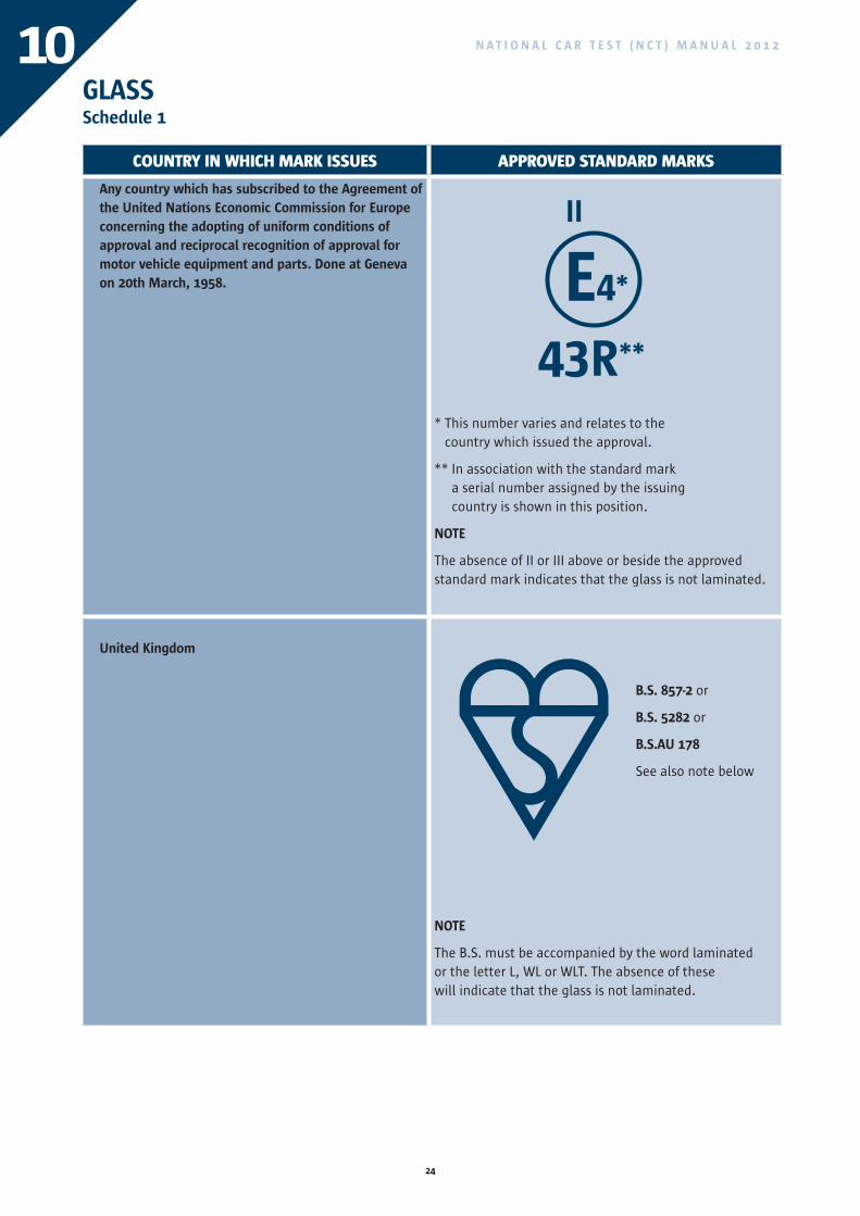
COUNTRY IN whICh MARk ISSUES APPROvED STANDARD MARkS
Any country which has subscribed to the Agreement of the United Nations Economic Commission for Europe concerning the adopting of uniform conditions of approval and reciprocal recognition of approval for motor vehicle equipment and parts. Done at Geneva on 20th March, 1958.
* This number varies and relates to the country which issued the approval.
** In association with the standard mark a serial number assigned by the issuing country is shown in this position.
NOTE
The absence of II or III above or beside the approved standard mark indicates that the glass is not laminated.
United Kingdom
NOTE
The B.S. must be accompanied by the word laminated or the letter L, WL or WLT. The absence of these will indicate that the glass is not laminated.
E4*
43R**
II
B.S. 857-2 or
B.S. 5282 or
B.S.AU 178
See also note below
10
25
N A T I O N A L C A R T E S T ( N C T ) M A N U A L 2 0 1 2 10GLASSSchedule 1
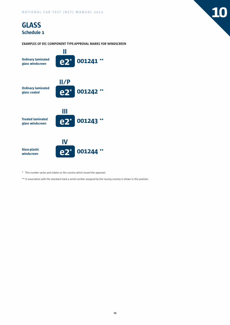
EXAMPLES OF EEC COMPONENT TYPE-APPROVAL MARKS FOR WINDSCREEN
* This number varies and relates to the country which issued the approval.
** In association with the standard mark a serial number assigned by the issuing country is shown in this position.
Ordinary laminated glass windscreen
Ordinary laminated glass coated
Treated laminated glass windscreen
Glass-plastic windscreen
e2*
e2*
e2*
e2*
II
II/P
III
IV
001241 **
001242 **
001243 **
001244 **
COUNTRY IN whICh MARk ISSUES APPROvED STANDARD MARkS
Any country which has subscribed to the Agreement of the United Nations Economic Commission for Europe concerning the adopting of uniform conditions of approval and reciprocal recognition of approval for motor vehicle equipment and parts. Done at Geneva on 20th March, 1958.
* This number varies and relates to the country which issued the approval.
** In association with the standard mark a serial number assigned by the issuing country is shown in this position.
NOTE
The absence of II or III above or beside the approved standard mark indicates that the glass is not laminated.
United Kingdom
NOTE
The B.S. must be accompanied by the word laminated or the letter L, WL or WLT. The absence of these will indicate that the glass is not laminated.
26
N A T I O N A L C A R T E S T ( N C T ) M A N U A L 2 0 1 210GLASS
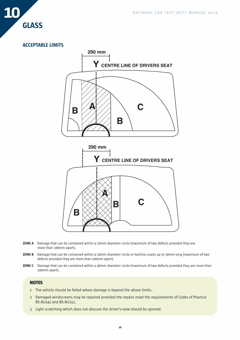
ACCEPTABLE LIMITS
ZONE A Damage that can be contained within a 10mm diameter circle (maximum of two defects provided they are more than 100mm apart).
ZONE B Damage that can be contained within a 20mm diameter circle or hairline cracks up to 30mm long (maximum of two defects provided they are more than 100mm apart).
ZONE C Damage that can be contained within a 40mm diameter circle (maximum of two defects provided they are more than 100mm apart).
NOTES
1 The vehicle should be failed where damage is beyond the above limits.
2 Damaged windscreens may be repaired provided the repairs meet the requirements of Codes of Practice BS AU242 and BS AU251.
3 Light scratching which does not obscure the driver’s view should be ignored.
290 mm
CENTRE LINE OF DRIVERS SEAT
CB
B A
290 mm
CBB
A
Y
CENTRE LINE OF DRIVERS SEATY
27
N A T I O N A L C A R T E S T ( N C T ) M A N U A L 2 0 1 2 11
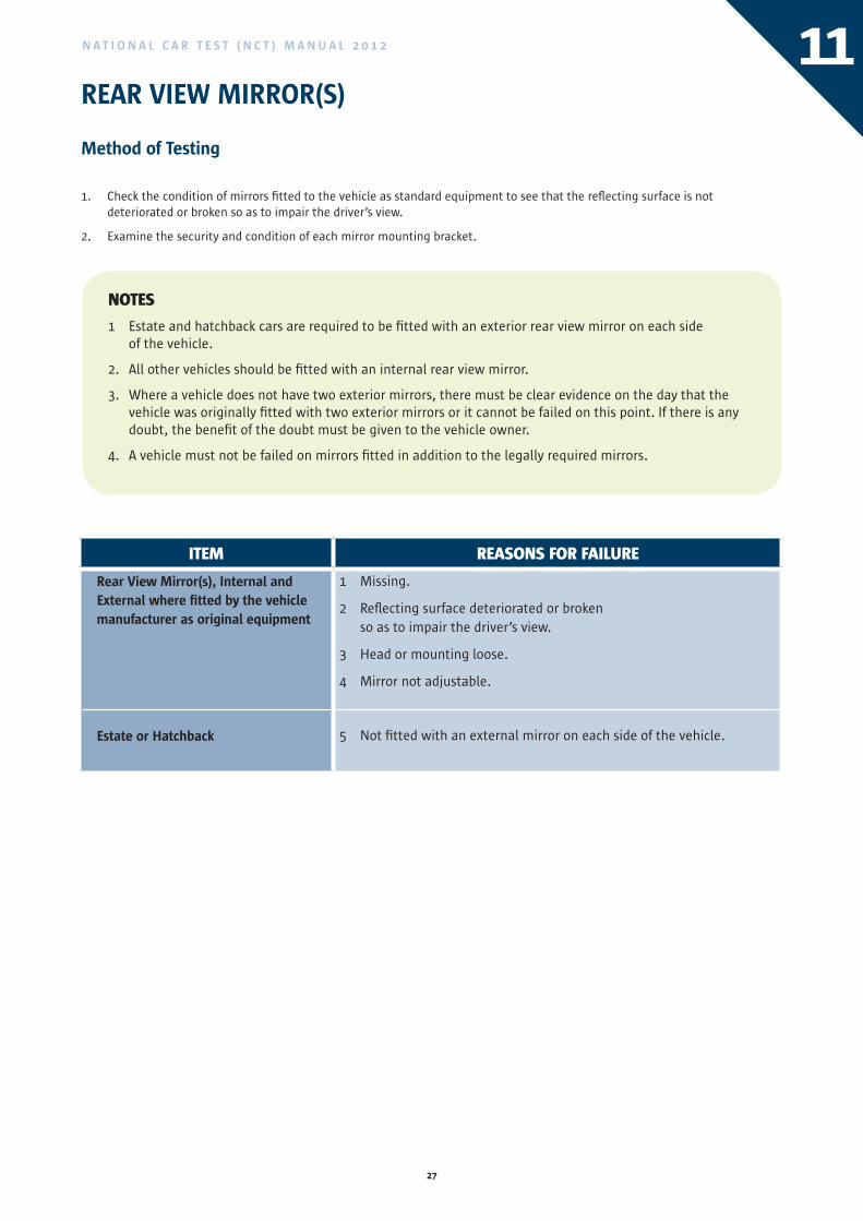
ITEM REASONS FOR FAILURE
Rear View Mirror(s), Internal andExternal where fitted by the vehiclemanufacturer as original equipment
Estate or Hatchback
1 Missing.
2 Reflecting surface deteriorated or broken so as to impair the driver’s view.
3 Head or mounting loose.
4 Mirror not adjustable.
5 Not fitted with an external mirror on each side of the vehicle.
REAR VIEW MIRROR(S)
Method of Testing
Check the condition of mirrors fitted to the vehicle as standard equipment to see that the reflecting surface is not 1. deteriorated or broken so as to impair the driver’s view.
Examine the security and condition of each mirror mounting bracket.2.
NOTES
1 Estate and hatchback cars are required to be fitted with an exterior rear view mirror on each side of the vehicle.
2. All other vehicles should be fitted with an internal rear view mirror.
3. Where a vehicle does not have two exterior mirrors, there must be clear evidence on the day that the vehicle was originally fitted with two exterior mirrors or it cannot be failed on this point. If there is any doubt, the benefit of the doubt must be given to the vehicle owner.
4. A vehicle must not be failed on mirrors fitted in addition to the legally required mirrors.
28
N A T I O N A L C A R T E S T ( N C T ) M A N U A L 2 0 1 212
ITEM REASONS FOR FAILURE
Speedometer
Lighting of Speedometer
1 Missing or not working.
2 Cannot be seen from driver’s seat.
3 Not working.
SPEEDOMETER
Method of Testing
Check that a speedometer is fitted, working and can be easily seen from the driving seat.1.
Check that the speedometer can be illuminated.2.
NOTES
1 The speedometer functions check is limited to the movement of the vehicle within the test area.
29
N A T I O N A L C A R T E S T ( N C T ) M A N U A L 2 0 1 2 13
ITEM REASONS FOR FAILURE
Safety Belts
Safety Belts (including belts of Child Restraint Systems)
Safety Belt and Child Restraint System Anchorage
1. For vehicles registered on or after the 1st day of June 1971, a lap and diagonal type safety belt is not provided for the driver and outer front seat.
2. For vehicles registered on or after the 1st day of January 1992:
(a) A lap and diagonal type belt is not provided for all outer forward facing seats.
(b) A lap and diagonal or lap type safety belt is not provided for all other forward facing seats.
Note: Safety belts which only operate when the vehicle is in motion should be checked when driving to or from the test lane.
3. Belts cut, badly frayed, or repaired.
4. Belts not operating properly (e.g. damaged buckles, loose or detached fixing bolts, retracting or locking mechanism not functioning properly as designed and manufactured).
Note: A safety belt that cannot be extended fully should fail.
5. Any load bearing member of the vehicle structure or panelling within 30 cm of an anchorage point cracked, corroded or in an otherwise weakened condition.
6. Belt mounting unsatisfactory (e.g. incorrect bolts fitted).
SAFETY BELTS(This item does not apply to vehicles registered before the 1st day of June 1971)
Method of Testing
For vehicles registered on or after the 1st day of June 1971, check that a lap and diagonal type safety belt is provided for the 1. driver and front outer passenger seat.
For vehicles registered on or after the 1st day of January 1992, check that all outer forward facing seats are provided with a lap 2. and diagonal type safety belt and all other forward facing seats are provided with a lap and diagonal or lap type safety belt.
Pull each safety belt webbing against its anchorage and see that it is properly secured to the vehicle structure.3.
Examine the condition of all safety belt webbing for cuts or obvious signs of deterioration. In the case of the retractable type 4. safety belt ensure that the belt is fully extended during this examination.
With the seat unoccupied, fasten the safety belt buckle and check that the adjustment mechanism functions properly. In the 5. case of retractable belts ensure that all the slack is removed and by pulling the belt quickly check that the locking mechanism operates. Attempt to separate the fastened belt at the buckle and check that the belt can be released when required.
Examine the condition of the attachment and adjustment fittings on each belt for distortion or fracture.6.
As far as is practicable without dismantling, check the condition of the vehicle structure in the vicinity of the safety belt 7. anchorage points. The condition of floor mounted anchorage points may best be inspected from underneath the vehicle.
NOTES
1 Where a vehicle is fitted with seat belts which can only be checked for operation by a road test, it will not be necessary to check the operation of the rear seat belts. Both front seat belts must be checked for operation; however, the visuals should make clear to the owner that the rear seat belts have not been checked for operation.
ITEM REASONS FOR FAILURE
Speedometer
Lighting of Speedometer
1 Missing or not working.
2 Cannot be seen from driver’s seat.
3 Not working.
30
N A T I O N A L C A R T E S T ( N C T ) M A N U A L 2 0 1 214STEERING WHEEL PLAY
Method of Testing
With the road-wheels in the straight-ahead position, lightly turn the steering wheel to the left and right as far as possible and 1. note the amount of free play before the road-wheels move. (If power steering is fitted the engine should be running).
Attempt to lift the steering wheel in line with the steering column and note any movement at the centre of the steering 2. wheel or the steering column.
Push steering wheel away and pull it towards your body, and note the movement of the steering column and its 3. security of mounting.
Examine the universal joints/flexible couplings for wear, security or deterioration.4.
Examine steering lock where fitted (see Item 15 for reasons for failure).5.
Check the presence and security of retaining and locking devices.6.
ITEM REASONS FOR FAILURE
Steering Box
Rack and Pinion
Steering Wheel/Column/Shaft
Universal Joint/Clamp
Retaining and Locking Devices
1 Excessive rotational play (20°).
2 Excessive rotational play (5°).
3 Excessive end float, insecure, broken.
4 Bushes/Bearings/Mounting brackets missing, worn, damaged or insecure.
5 Shear pin in telescopic column broken.
6 Damaged, worn, insecure or badly deteriorated.
7 A retaining or locking device missing or insecure.
NOTE ON ROTATIONAL PLAY
Steering Box
20° on 15” (381mm) diameter wheel = 67mm on rim
20° on 18” (457mm) diameter wheel = 80mm on rim
Rack and Pinion
5° on 15” (381mm) diameter wheel = 17mm on rim
5° on 1 8” (457mm) diameter wheel = 20mm on rim
NOTES
1. Where a steering mechanism is fitted with flexible couplings care must be taken to distinguish between play due to wear, and apparent play due to the construction of the mechanism.
31
N A T I O N A L C A R T E S T ( N C T ) M A N U A L 2 0 1 2
DOOR/LOCKS/ANTI-THEFT DEVICES
Method of Testing
Examine the general condition of all doors.
1. Open each door and check the security of catches and receivers.
2. Close the door and, without using the handle, note whether the door primary and secondary catches hold the door closed.
3. By opening and closing each door note whether the door pillars are sound (see Item 35 for reasons for failure).
4. If the vehicle is fitted with sliding doors examine the condition of the runners and tracks and actuating mechanism.
5. Check that the steering lock is not fouling the steering mechanism when the ignition is switched on.
15
ITEM REASONS FOR FAILURE
Doors
Sliding Doors
Steering Lock (where originally fitted)
1 A door missing.
2 Door cannot be shut or opened normally or is liable to open on its own.
3 Insecure receivers or catch.
4 Runners, tracks, or actuating mechanism so defective that the door does not open or close properly.
5 A door missing.
6 Safety devices not working or defective.
7 Excessive wear or jamming of lock/barrel/key mechanism of a steering lock.
ITEM REASONS FOR FAILURE
Steering Box
Rack and Pinion
Steering Wheel/Column/Shaft
Universal Joint/Clamp
Retaining and Locking Devices
1 Excessive rotational play (20°).
2 Excessive rotational play (5°).
3 Excessive end float, insecure, broken.
4 Bushes/Bearings/Mounting brackets missing, worn, damaged or insecure.
5 Shear pin in telescopic column broken.
6 Damaged, worn, insecure or badly deteriorated.
7 A retaining or locking device missing or insecure.
NOTE ON ROTATIONAL PLAY
Steering Box
20° on 15” (381mm) diameter wheel = 67mm on rim
20° on 18” (457mm) diameter wheel = 80mm on rim
Rack and Pinion
5° on 15” (381mm) diameter wheel = 17mm on rim
5° on 1 8” (457mm) diameter wheel = 20mm on rim
32
N A T I O N A L C A R T E S T ( N C T ) M A N U A L 2 0 1 216ADAPTATIONS FOR DISABLED DRIVERS (where fitted)
Method of Testing
Check all adaptations for disabled drivers to ensure that they operate freely, are secure, free from excessive wear and not likely to fail.
ITEM REASONS FOR FAILURE
Adaptations for Disabled Drivers 1 Worn, insecure, sticking, fouling or likely to fail.
2 Servo or electrical devices defective.
3 Wiring insecure, insulation damaged, likely to short circuit or fail.
33
N A T I O N A L C A R T E S T ( N C T ) M A N U A L 2 0 1 2 17FRONT WHEEL SIDE SLIP
Method of Testing
Drive the R/H front wheel slowly and straight over the side slip plate without moving the steering wheel or applying the brakes and note the reading.
ITEM REASONS FOR FAILURE
Side Slip More than ± 14m/km.
NOTES
1. When explaining defects to vehicle owners or garages, side slip may be referred to as steering geometry.ITEM REASONS FOR FAILURE
Adaptations for Disabled Drivers 1 Worn, insecure, sticking, fouling or likely to fail.
2 Servo or electrical devices defective.
3 Wiring insecure, insulation damaged, likely to short circuit or fail.
34
N A T I O N A L C A R T E S T ( N C T ) M A N U A L 2 0 1 218REAR WHEEL SIDE SLIP
Method of Testing
Drive the R/H rear wheel slowly and straight over the side slip plate without moving the steering wheel or applying the brakes and note the reading.
ITEM REASONS FOR FAILURE
Side Slip More than ± 18m/km.
35
N A T I O N A L C A R T E S T ( N C T ) M A N U A L 2 0 1 2 19FRONT AXLE SUSPENSION PERFORMANCE
Method of Testing
Drive the front wheels of the vehicle into the suspension performance tester and operate as per manufacturer’s instructions.
ITEM REASONS FOR FAILURE
Front Suspension Performance More than 30% imbalance between L/H and R/H suspension.
ITEM REASONS FOR FAILURE
Side Slip More than ± 18m/km.
36
N A T I O N A L C A R T E S T ( N C T ) M A N U A L 2 0 1 220REAR AXLE SUSPENSION PERFORMANCE
Method of Testing
Drive the rear wheels of the vehicle into the suspension performance tester and operate as per manufacturer’s instructions.
ITEM REASONS FOR FAILURE
Rear Suspension Performance More than 30% imbalance between L/H and R/H suspensions.
37
N A T I O N A L C A R T E S T ( N C T ) M A N U A L 2 0 1 2 21SERVICE BRAKE PERFORMANCE
Method of Testing
Roller Brake Test
If the Vehicle is of a type which can be tested on the roller brake test machine proceed as follows.
1. Position the vehicle so that the wheels of each axle can in turn be placed on the brake test machine rollers.
2. Drive the vehicle onto the roller brake tester and following the prompts of the brake tester programme apply the service brake.
3. Check that the brake can be applied progressively and when released does not show any abnormal lag.
NOTES
1. Tyres must be correctly inflated and the gear selector should be in the neutral position.
2. The testing of vehicles fitted with ice studded tyres will damage the brake tester roller friction surface. It is advisable to ensure before the roller brake test that the tyres are not damaged and are free from stones embedded in the tread.
3. Vehicles having automatic transmission must not be tested with the gear selector in the “P” park position.
4. Occasions will arise when the required brake efficiency is just obtained or just exceeded without lock occurring but the tester knows that a higher performance figure is normally obtainable for the type of vehicle being tested. In such cases although the vehicle has passed the brake performance test, the tester should advise the owner that the braking system appears to be in need of adjustment or repair.
5. For vehicles with servo assisted or power braking systems, the engine must be running (idling) when the service brake is tested.
6. In some cases it may be necessary to chock the road-wheels of the vehicle during a roller brake test.
7. Care should be taken to ensure that tyres are free from mud, stones, oil, or water and that brake tester rollers are in good condition to ensure that premature wheel slip does not occur.
8. The use of a roller brake tester is not appropriate on hybrid vehicles or on vehicles with a permanently engaged four wheel drive, limited slip differential or belt driven transmission.
9. Where a vehicle cannot be tested on a roller brake tester because of additional spoilers fitted, they must be removed by the owner/presenter before the test. A decelerometer test will not suffice in this situation.
ITEM REASONS FOR FAILURE
Rear Suspension Performance More than 30% imbalance between L/H and R/H suspensions.
38
N A T I O N A L C A R T E S T ( N C T ) M A N U A L 2 0 1 221SERVICE BRAKE PERFORMANCE
Method of Testing
Decelerometer Test
If the vehicle is of a type that cannot be tested on the roller brake test machine it should be subject to a decelerometer test as follows:
1. With the vehicle on a reasonably level road place the decelerometer on the floor of the vehicle and following the manufacturer’s instructions set it in the zero position.
2. Have the vehicle driven at a speed of approximately 20 – 30 M.P.H. (32 – 48 km/h). Have the service brake applied firmly and note the reading on the decelerometer.
ITEM REASONS FOR FAILURE
Service Brake 1 The braking effort a) for vehicles regisrtered before 28 July 2010 is less
than 55% of the test weight of the vehicle.
b) for vehicles registered on or after 28 July 2010 is less than 58% of the test weight of the vehicle.
2 Brake cannot be operated progressively.
3 Brake shows abnormal lag when released.
4 Brake effort on any wheel is less than 25kgf.
39
N A T I O N A L C A R T E S T ( N C T ) M A N U A L 2 0 1 2 22SERVICE BRAKE IMBALANCE
Method of Testing
Normally this test and the service brake performance test will be carried out concurrently and the same general precautions 1. apply (see ‘Method of Testing’ and ‘Notes’ for service brake performance).
Roller Brake Test 2. With the roller brake test machine driving the wheels of each axle in turn, apply the service brake slowly and note the braking effort indicated from the brake on each road-wheel.
Road Test (if carried out) 3. Where a road test is carried out, this should be done in traffic-free circumstances at a speed of 48km/h (30mph) Note whether the vehicle pulls to one side when the brakes are applied and if there is any evidence of brake drum/disc ovality.
ITEM REASONS FOR FAILURE
Wheels on Same Axle
Individual Wheel
Road Test (where carried out)
1 More than 30% difference in braking effort (i.e. the braking effort on one side should not be less than 70% of the braking effort on the other side).
2 Brake effort fluctuates by more than 30%.
3 Obvious pull to one side when brakes are applied.
4 Perceptible ovality.
NOTE Imbalance should not be considered where L/H and R/H brake efforts are at or below 40kgf.
ITEM REASONS FOR FAILURE
Service Brake 1 The braking effort a) for vehicles regisrtered before 28 July 2010 is less
than 55% of the test weight of the vehicle.
b) for vehicles registered on or after 28 July 2010 is less than 58% of the test weight of the vehicle.
2 Brake cannot be operated progressively.
3 Brake shows abnormal lag when released.
4 Brake effort on any wheel is less than 25kgf.
40
N A T I O N A L C A R T E S T ( N C T ) M A N U A L 2 0 1 223PARKING BRAKE PERFORMANCE
Method of Testing
Roller Brake Test
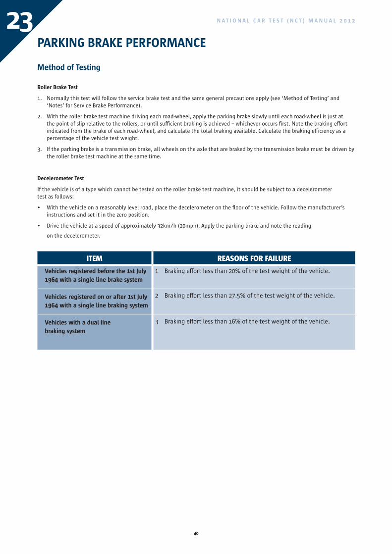
1. Normally this test will follow the service brake test and the same general precautions apply (see ‘Method of Testing’ and ‘Notes’ for Service Brake Performance).
2. With the roller brake test machine driving each road-wheel, apply the parking brake slowly until each road-wheel is just at the point of slip relative to the rollers, or until sufficient braking is achieved – whichever occurs first. Note the braking effort indicated from the brake of each road-wheel, and calculate the total braking available. Calculate the braking efficiency as a percentage of the vehicle test weight.
3. If the parking brake is a transmission brake, all wheels on the axle that are braked by the transmission brake must be driven by the roller brake test machine at the same time.
Decelerometer Test
If the vehicle is of a type which cannot be tested on the roller brake test machine, it should be subject to a decelerometer test as follows:
• With the vehicle on a reasonably level road, place the decelerometer on the floor of the vehicle. Follow the manufacturer’s instructions and set it in the zero position.
• Drive the vehicle at a speed of approximately 32km/h (20mph). Apply the parking brake and note the reading
on the decelerometer.
ITEM REASONS FOR FAILURE
Vehicles registered before the 1st July1964 with a single line brake system
Vehicles registered on or after 1st July 1964 with a single line braking system
Vehicles with a dual line braking system
1 Braking effort less than 20% of the test weight of the vehicle.
2 Braking effort less than 27.5% of the test weight of the vehicle.
3 Braking effort less than 16% of the test weight of the vehicle.
41
N A T I O N A L C A R T E S T ( N C T ) M A N U A L 2 0 1 2 24PARKING BRAKE IMBALANCE
Method of Testing
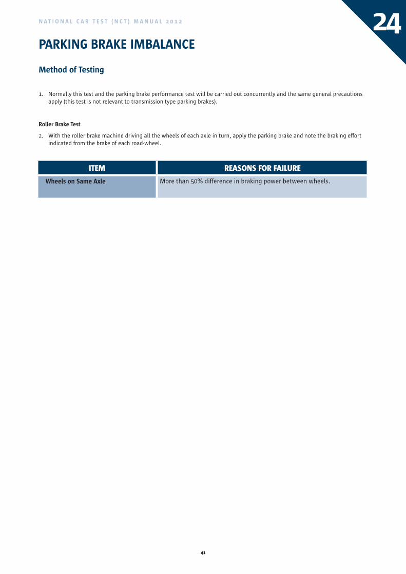
1. Normally this test and the parking brake performance test will be carried out concurrently and the same general precautions apply (this test is not relevant to transmission type parking brakes).
Roller Brake Test
2. With the roller brake machine driving all the wheels of each axle in turn, apply the parking brake and note the braking effort indicated from the brake of each road-wheel.
ITEM REASONS FOR FAILURE
Wheels on Same Axle More than 50% difference in braking power between wheels.
ITEM REASONS FOR FAILURE
Vehicles registered before the 1st July1964 with a single line brake system
Vehicles registered on or after 1st July 1964 with a single line braking system
Vehicles with a dual line braking system
1 Braking effort less than 20% of the test weight of the vehicle.
2 Braking effort less than 27.5% of the test weight of the vehicle.
3 Braking effort less than 16% of the test weight of the vehicle.
42
N A T I O N A L C A R T E S T ( N C T ) M A N U A L 2 0 1 225TOWING BRACKET/COUPLING
Method of Testing
Drawing Coupling
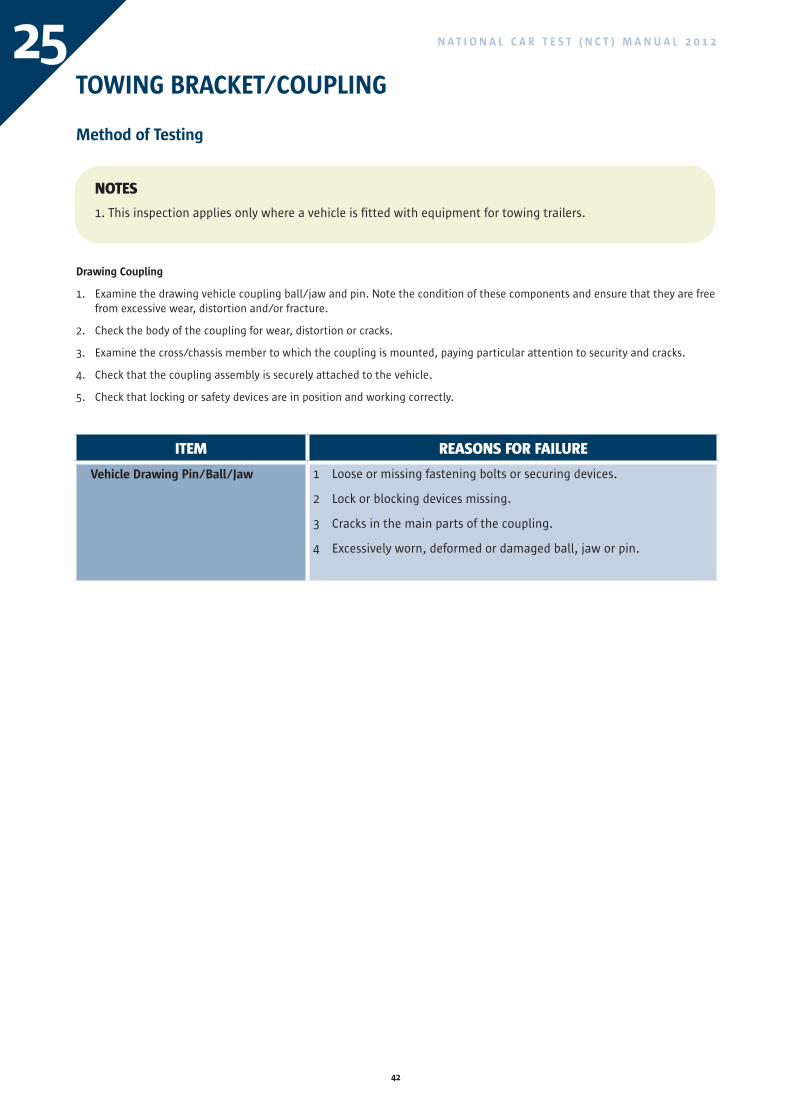
1. Examine the drawing vehicle coupling ball/jaw and pin. Note the condition of these components and ensure that they are free from excessive wear, distortion and/or fracture.
2. Check the body of the coupling for wear, distortion or cracks.
3. Examine the cross/chassis member to which the coupling is mounted, paying particular attention to security and cracks.
4. Check that the coupling assembly is securely attached to the vehicle.
5. Check that locking or safety devices are in position and working correctly.
ITEM REASONS FOR FAILURE
Vehicle Drawing Pin/Ball/Jaw 1 Loose or missing fastening bolts or securing devices.
2 Lock or blocking devices missing.
3 Cracks in the main parts of the coupling.
4 Excessively worn, deformed or damaged ball, jaw or pin.
NOTES
1. This inspection applies only where a vehicle is fitted with equipment for towing trailers.
43
N A T I O N A L C A R T E S T ( N C T ) M A N U A L 2 0 1 2 26
ITEM REASONS FOR FAILURE
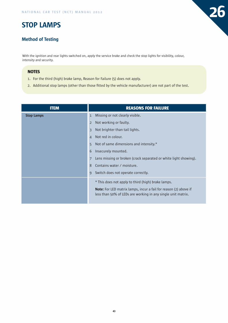
Stop Lamps 1 Missing or not clearly visible.
2 Not working or faulty.
3 Not brighter than tail lights.
4 Not red in colour.
5 Not of same dimensions and intensity.*
6 Insecurely mounted.
7 Lens missing or broken (crack separated or white light showing).
8 Contains water / moisture.
9 Switch does not operate correctly.
* This does not apply to third (high) brake lamps.
Note: For LED matrix lamps, incur a fail for reason (2) above if less than 50% of LEDs are working in any single unit matrix.
NOTES
1. For the third (high) brake lamp, Reason for Failure (5) does not apply.
2. Additional stop lamps (other than those fitted by the vehicle manufacturer) are not part of the test.
STOP LAMPS
Method of Testing
With the ignition and rear lights switched on, apply the service brake and check the stop lights for visibility, colour, intensity and security.
ITEM REASONS FOR FAILURE
Vehicle Drawing Pin/Ball/Jaw 1 Loose or missing fastening bolts or securing devices.
2 Lock or blocking devices missing.
3 Cracks in the main parts of the coupling.
4 Excessively worn, deformed or damaged ball, jaw or pin.
44
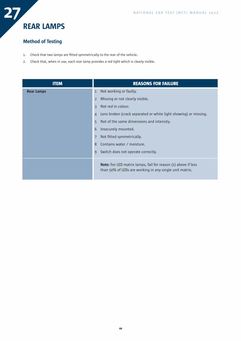
N A T I O N A L C A R T E S T ( N C T ) M A N U A L 2 0 1 227REAR LAMPS
Method of Testing
Check that two lamps are fitted symmetrically to the rear of the vehicle.1.
Check that, when in use, each rear lamp provides a red light which is clearly visible.2.
ITEM REASONS FOR FAILURE
Rear Lamps 1 Not working or faulty.
2 Missing or not clearly visible.
3 Not red in colour.
4 Lens broken (crack separated or white light showing) or missing.
5 Not of the same dimensions and intensity.
6 Insecurely mounted.
7 Not fitted symmetrically.
8 Contains water / moisture.
9 Switch does not operate correctly.
Note: For LED matrix lamps, fail for reason (1) above if less than 50% of LEDs are working in any single unit matrix.
45
N A T I O N A L C A R T E S T ( N C T ) M A N U A L 2 0 1 2
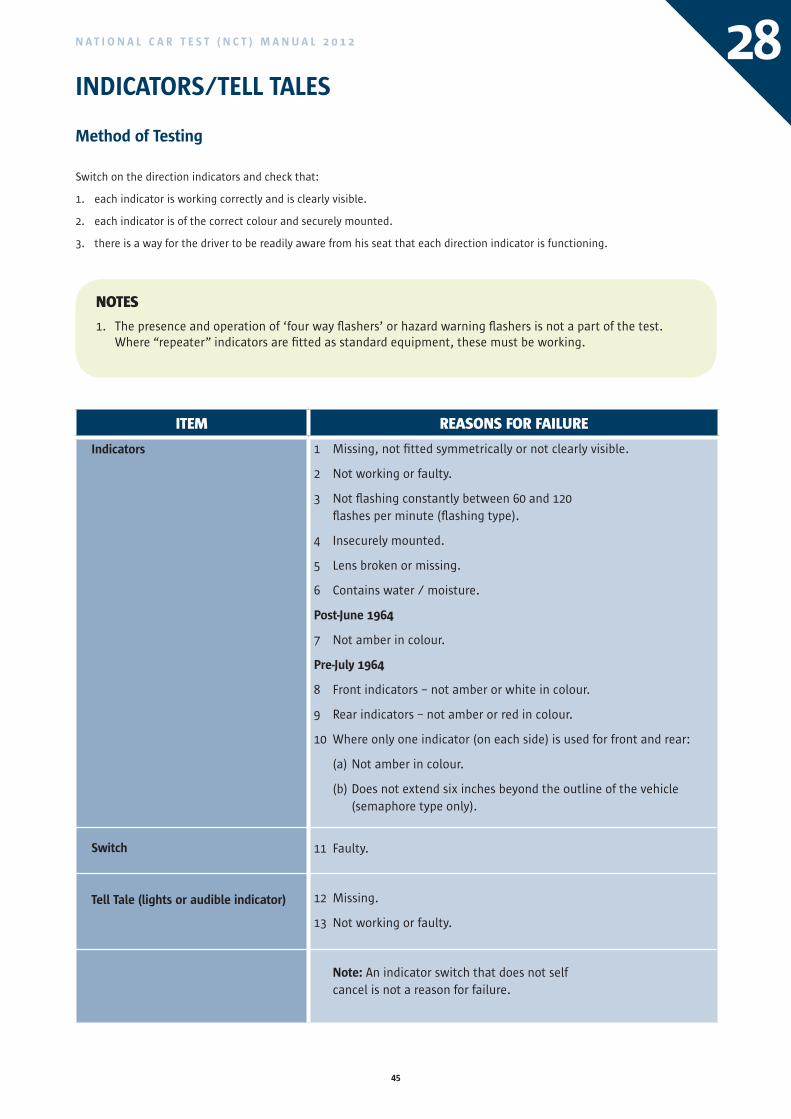
ITEM REASONS FOR FAILURE
Indicators
Switch
Tell Tale (lights or audible indicator)
1 Missing, not fitted symmetrically or not clearly visible.
2 Not working or faulty.
3 Not flashing constantly between 60 and 120 flashes per minute (flashing type).
4 Insecurely mounted.
5 Lens broken or missing.
6 Contains water / moisture.
Post-June 1964
7 Not amber in colour.
Pre-July 1964
8 Front indicators – not amber or white in colour.
9 Rear indicators – not amber or red in colour.
10 Where only one indicator (on each side) is used for front and rear:
(a) Not amber in colour.
(b) Does not extend six inches beyond the outline of the vehicle (semaphore type only).
11 Faulty.
12 Missing.
13 Not working or faulty.
Note: An indicator switch that does not self cancel is not a reason for failure.
28INDICATORS/TELL TALES
Method of Testing
Switch on the direction indicators and check that:
1. each indicator is working correctly and is clearly visible.
2. each indicator is of the correct colour and securely mounted.
3. there is a way for the driver to be readily aware from his seat that each direction indicator is functioning.
NOTES
1. The presence and operation of ‘four way flashers’ or hazard warning flashers is not a part of the test. Where “repeater” indicators are fitted as standard equipment, these must be working.
46
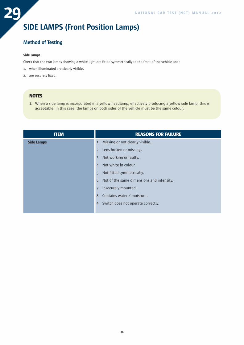
N A T I O N A L C A R T E S T ( N C T ) M A N U A L 2 0 1 229SIDE LAMPS (Front Position Lamps)
Method of Testing
Side Lamps
Check that the two lamps showing a white light are fitted symmetrically to the front of the vehicle and:
1. when illuminated are clearly visible.
2. are securely fixed.
ITEM REASONS FOR FAILURE
Side Lamps 1 Missing or not clearly visible.
2 Lens broken or missing.
3 Not working or faulty.
4 Not white in colour.
5 Not fitted symmetrically.
6 Not of the same dimensions and intensity.
7 Insecurely mounted.
8 Contains water / moisture.
9 Switch does not operate correctly.
NOTES
1. When a side lamp is incorporated in a yellow headlamp, effectively producing a yellow side lamp, this is acceptable. In this case, the lamps on both sides of the vehicle must be the same colour.
47
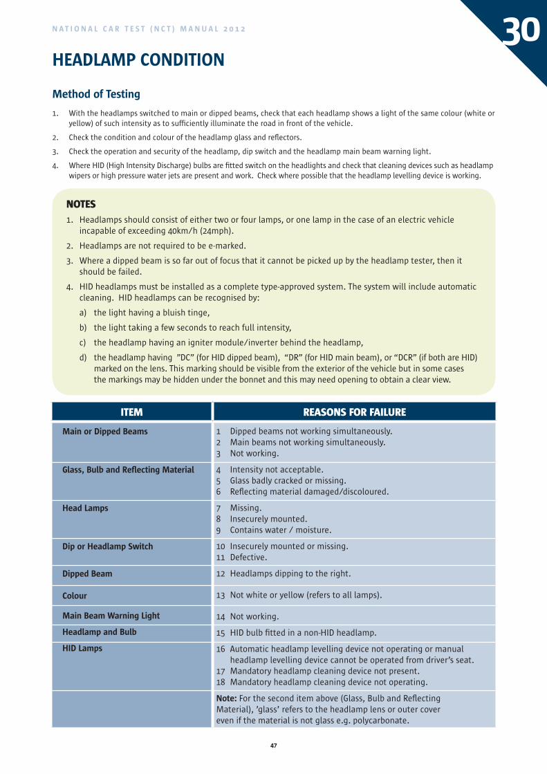
N A T I O N A L C A R T E S T ( N C T ) M A N U A L 2 0 1 2 30HEADLAMP CONDITION
Method of Testing
With the headlamps switched to main or dipped beams, check that each headlamp shows a light of the same colour (white or 1. yellow) of such intensity as to sufficiently illuminate the road in front of the vehicle.
Check the condition and colour of the headlamp glass and reflectors.2.
Check the operation and security of the headlamp, dip switch and the headlamp main beam warning light.3.
Where HID (High Intensity Discharge) bulbs are fitted switch on the headlights and check that cleaning devices such as headlamp 4. wipers or high pressure water jets are present and work. Check where possible that the headlamp levelling device is working.
NOTES
1. Headlamps should consist of either two or four lamps, or one lamp in the case of an electric vehicle incapable of exceeding 40km/h (24mph).
2. Headlamps are not required to be e-marked.
3. Where a dipped beam is so far out of focus that it cannot be picked up by the headlamp tester, then it should be failed.
4. HID headlamps must be installed as a complete type-approved system. The system will include automatic cleaning. HID headlamps can be recognised by:
a) the light having a bluish tinge,
b) the light taking a few seconds to reach full intensity,
c) the headlamp having an igniter module/inverter behind the headlamp,
d) the headlamp having ”DC” (for HID dipped beam), “DR” (for HID main beam), or “DCR” (if both are HID) marked on the lens. This marking should be visible from the exterior of the vehicle but in some cases the markings may be hidden under the bonnet and this may need opening to obtain a clear view.
ITEM REASONS FOR FAILURE
Main or Dipped Beams
Glass, Bulb and Reflecting Material
Head Lamps
Dip or Headlamp Switch
Dipped Beam Colour
Main Beam Warning Light
Headlamp and Bulb
HID Lamps
1 Dipped beams not working simultaneously. 2 Main beams not working simultaneously. 3 Not working.
4 Intensity not acceptable. 5 Glass badly cracked or missing. 6 Reflecting material damaged/discoloured.
7 Missing. 8 Insecurely mounted. 9 Contains water / moisture.
10 Insecurely mounted or missing. 11 Defective.
12 Headlamps dipping to the right.
13 Not white or yellow (refers to all lamps).
14 Not working.
15 HID bulb fitted in a non-HID headlamp.
16 Automatic headlamp levelling device not operating or manual headlamp levelling device cannot be operated from driver’s seat.
17 Mandatory headlamp cleaning device not present.18 Mandatory headlamp cleaning device not operating.
Note: For the second item above (Glass, Bulb and Reflecting Material), ’glass’ refers to the headlamp lens or outer cover even if the material is not glass e.g. polycarbonate.
ITEM REASONS FOR FAILURE
Side Lamps 1 Missing or not clearly visible.
2 Lens broken or missing.
3 Not working or faulty.
4 Not white in colour.
5 Not fitted symmetrically.
6 Not of the same dimensions and intensity.
7 Insecurely mounted.
8 Contains water / moisture.
9 Switch does not operate correctly.
48
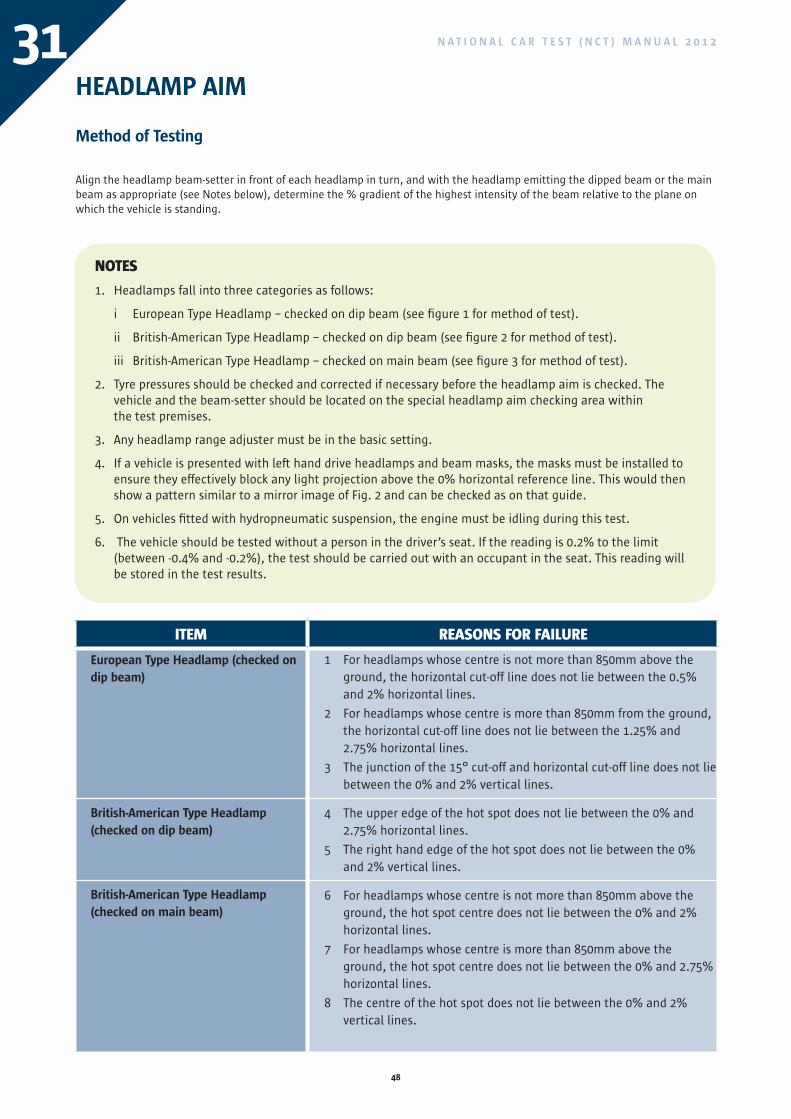
N A T I O N A L C A R T E S T ( N C T ) M A N U A L 2 0 1 231HEADLAMP AIM
Method of Testing
Align the headlamp beam-setter in front of each headlamp in turn, and with the headlamp emitting the dipped beam or the main beam as appropriate (see Notes below), determine the % gradient of the highest intensity of the beam relative to the plane on which the vehicle is standing.
NOTES
1. Headlamps fall into three categories as follows:
i European Type Headlamp – checked on dip beam (see figure 1 for method of test).
ii British-American Type Headlamp – checked on dip beam (see figure 2 for method of test).
iii British-American Type Headlamp – checked on main beam (see figure 3 for method of test).
2. Tyre pressures should be checked and corrected if necessary before the headlamp aim is checked. The vehicle and the beam-setter should be located on the special headlamp aim checking area within the test premises.
3. Any headlamp range adjuster must be in the basic setting.
4. If a vehicle is presented with left hand drive headlamps and beam masks, the masks must be installed to ensure they effectively block any light projection above the 0% horizontal reference line. This would then show a pattern similar to a mirror image of Fig. 2 and can be checked as on that guide.
5. On vehicles fitted with hydropneumatic suspension, the engine must be idling during this test.
6. The vehicle should be tested without a person in the driver’s seat. If the reading is 0.2% to the limit (between -0.4% and -0.2%), the test should be carried out with an occupant in the seat. This reading will be stored in the test results.
ITEM REASONS FOR FAILURE
European Type Headlamp (checked on dip beam)
British-American Type Headlamp (checked on dip beam)
British-American Type Headlamp (checked on main beam)
1 For headlamps whose centre is not more than 850mm above the ground, the horizontal cut-off line does not lie between the 0.5% and 2% horizontal lines.
2 For headlamps whose centre is more than 850mm from the ground, the horizontal cut-off line does not lie between the 1.25% and 2.75% horizontal lines.
3 The junction of the 15° cut-off and horizontal cut-off line does not lie between the 0% and 2% vertical lines.
4 The upper edge of the hot spot does not lie between the 0% and 2.75% horizontal lines.
5 The right hand edge of the hot spot does not lie between the 0% and 2% vertical lines.
6 For headlamps whose centre is not more than 850mm above the ground, the hot spot centre does not lie between the 0% and 2% horizontal lines.
7 For headlamps whose centre is more than 850mm above the ground, the hot spot centre does not lie between the 0% and 2.75% horizontal lines.
8 The centre of the hot spot does not lie between the 0% and 2% vertical lines.
49
N A T I O N A L C A R T E S T ( N C T ) M A N U A L 2 0 1 2
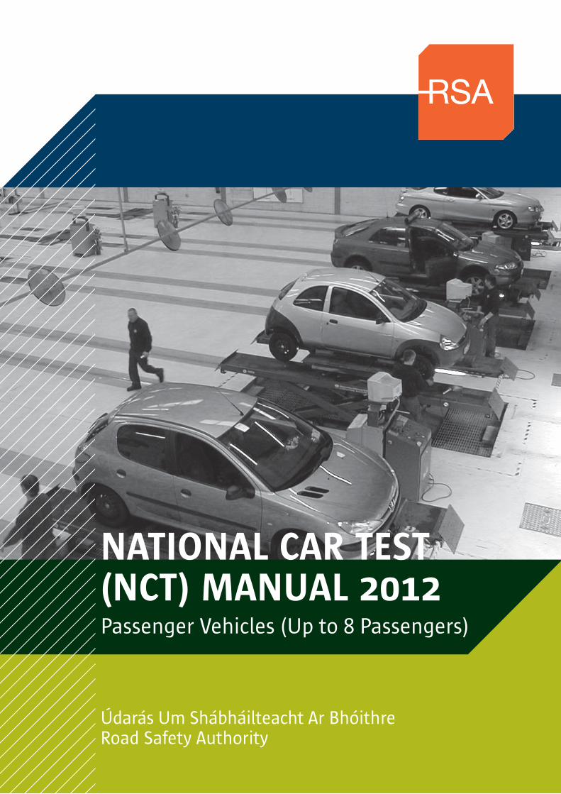
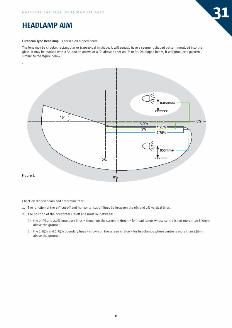
Check on dipped beam and determine that:
1. The junction of the 15° cut-off and horizontal cut-off lines lie between the 0% and 2% vertical lines.
2. The position of the horizontal cut-off line must lie between:
(i) the 0.5% and 2.0% boundary lines – shown on the screen in Green – for head lamps whose centre is not more than 850mm above the ground;.
(ii) the 1.25% and 2.75% boundary lines – shown on the screen in Blue – for headlamps whose centre is more than 850mm above the ground.
31HEADLAMP AIM
European Type Headlamp – checked on dipped beam.
The lens may be circular, rectangular or trapezoidal in shape. It will usually have a segment shaped pattern moulded into the glass. It may be marked with a ‘2’ and an arrow, or a ‘C’ above either an ‘E’ or ‘e’. On dipped beam, it will produce a pattern similar to the figure below.
.
0-850mm
1.25%2.75%
850mm+
2%
0%
150%
2%0.5%
O
Figure 1
ITEM REASONS FOR FAILURE
European Type Headlamp (checked on dip beam)
British-American Type Headlamp (checked on dip beam)
British-American Type Headlamp (checked on main beam)
1 For headlamps whose centre is not more than 850mm above the ground, the horizontal cut-off line does not lie between the 0.5% and 2% horizontal lines.
2 For headlamps whose centre is more than 850mm from the ground, the horizontal cut-off line does not lie between the 1.25% and 2.75% horizontal lines.
3 The junction of the 15° cut-off and horizontal cut-off line does not lie between the 0% and 2% vertical lines.
4 The upper edge of the hot spot does not lie between the 0% and 2.75% horizontal lines.
5 The right hand edge of the hot spot does not lie between the 0% and 2% vertical lines.
6 For headlamps whose centre is not more than 850mm above the ground, the hot spot centre does not lie between the 0% and 2% horizontal lines.
7 For headlamps whose centre is more than 850mm above the ground, the hot spot centre does not lie between the 0% and 2.75% horizontal lines.
8 The centre of the hot spot does not lie between the 0% and 2% vertical lines.
50
N A T I O N A L C A R T E S T ( N C T ) M A N U A L 2 0 1 231
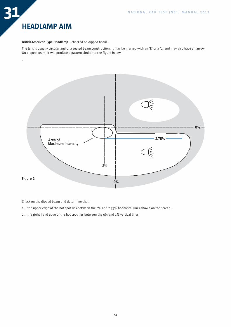
Check on the dipped beam and determine that:
1. the upper edge of the hot spot lies between the 0% and 2.75% horizontal lines shown on the screen.
2. the right hand edge of the hot spot lies between the 0% and 2% vertical lines.
HEADLAMP AIM
British-American Type Headlamp – checked on dipped beam.
The lens is usually circular and of a sealed beam construction. It may be marked with an ‘E’ or a ‘2’ and may also have an arrow. On dipped beam, it will produce a pattern similar to the figure below.
.
2.75%
2%
0%
0%
Area ofMaximum Intensity
Figure 2
51
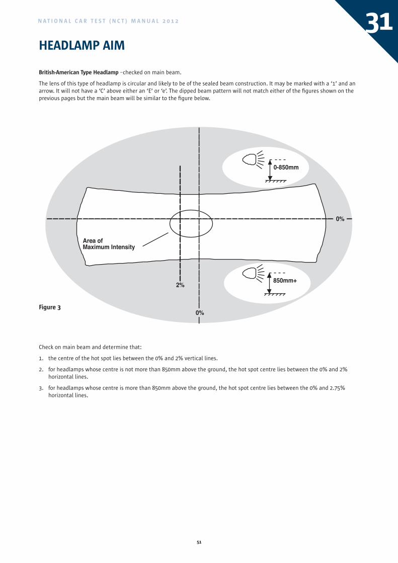
N A T I O N A L C A R T E S T ( N C T ) M A N U A L 2 0 1 2 31
Check on main beam and determine that:
1. the centre of the hot spot lies between the 0% and 2% vertical lines.
2. for headlamps whose centre is not more than 850mm above the ground, the hot spot centre lies between the 0% and 2% horizontal lines.
3. for headlamps whose centre is more than 850mm above the ground, the hot spot centre lies between the 0% and 2.75% horizontal lines.
HEADLAMP AIM
British-American Type Headlamp –checked on main beam.
The lens of this type of headlamp is circular and likely to be of the sealed beam construction. It may be marked with a ‘1’ and an arrow. It will not have a ‘C’ above either an ‘E’ or ‘e’. The dipped beam pattern will not match either of the figures shown on the previous pages but the main beam will be similar to the figure below.
0-850mm
850mm+2%
0%
0%
Area ofMaximum Intensity
Figure 3
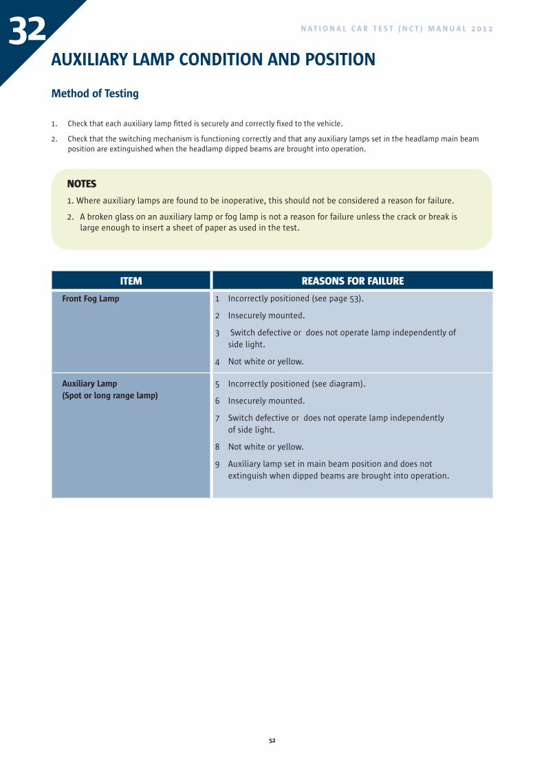
52
N A T I O N A L C A R T E S T ( N C T ) M A N U A L 2 0 1 232AUXILIARY LAMP CONDITION AND POSITION
Method of Testing
Check that each auxiliary lamp fitted is securely and correctly fixed to the vehicle.1.
Check that the switching mechanism is functioning correctly and that any auxiliary lamps set in the headlamp main beam 2. position are extinguished when the headlamp dipped beams are brought into operation.
NOTES
1. Where auxiliary lamps are found to be inoperative, this should not be considered a reason for failure.
2. A broken glass on an auxiliary lamp or fog lamp is not a reason for failure unless the crack or break is large enough to insert a sheet of paper as used in the test.
ITEM REASONS FOR FAILURE
Front Fog Lamp
Auxiliary Lamp(Spot or long range lamp)
1 Incorrectly positioned (see page 53).
2 Insecurely mounted.
3 Switch defective or does not operate lamp independently of side light.
4 Not white or yellow.
5 Incorrectly positioned (see diagram).
6 Insecurely mounted.
7 Switch defective or does not operate lamp independently of side light.
8 Not white or yellow.
9 Auxiliary lamp set in main beam position and does not extinguish when dipped beams are brought into operation.
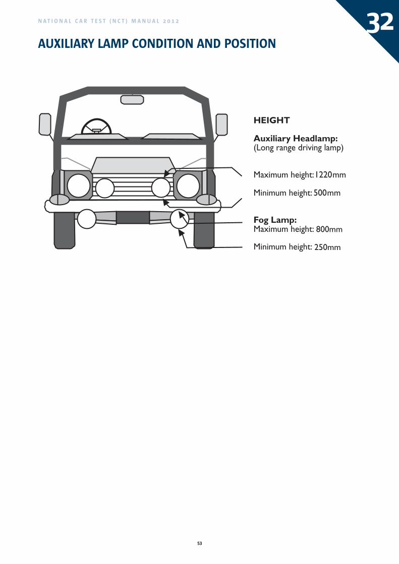
53
N A T I O N A L C A R T E S T ( N C T ) M A N U A L 2 0 1 2 32AUXILIARY LAMP CONDITION AND POSITION
800mm
250mm
ITEM REASONS FOR FAILURE
Front Fog Lamp
Auxiliary Lamp(Spot or long range lamp)
1 Incorrectly positioned (see page 53).
2 Insecurely mounted.
3 Switch defective or does not operate lamp independently of side light.
4 Not white or yellow.
5 Incorrectly positioned (see diagram).
6 Insecurely mounted.
7 Switch defective or does not operate lamp independently of side light.
8 Not white or yellow.
9 Auxiliary lamp set in main beam position and does not extinguish when dipped beams are brought into operation.
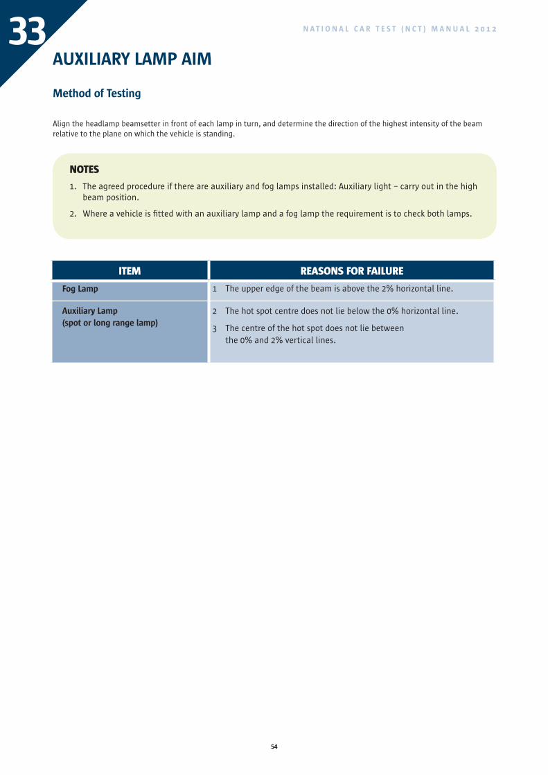
54
N A T I O N A L C A R T E S T ( N C T ) M A N U A L 2 0 1 233AUXILIARY LAMP AIM
Method of Testing
Align the headlamp beamsetter in front of each lamp in turn, and determine the direction of the highest intensity of the beam relative to the plane on which the vehicle is standing.
NOTES
1. The agreed procedure if there are auxiliary and fog lamps installed: Auxiliary light – carry out in the high beam position.
2. Where a vehicle is fitted with an auxiliary lamp and a fog lamp the requirement is to check both lamps.
ITEM REASONS FOR FAILURE
Fog Lamp
Auxiliary Lamp(spot or long range lamp)
1 The upper edge of the beam is above the 2% horizontal line.
2 The hot spot centre does not lie below the 0% horizontal line.
3 The centre of the hot spot does not lie between the 0% and 2% vertical lines.
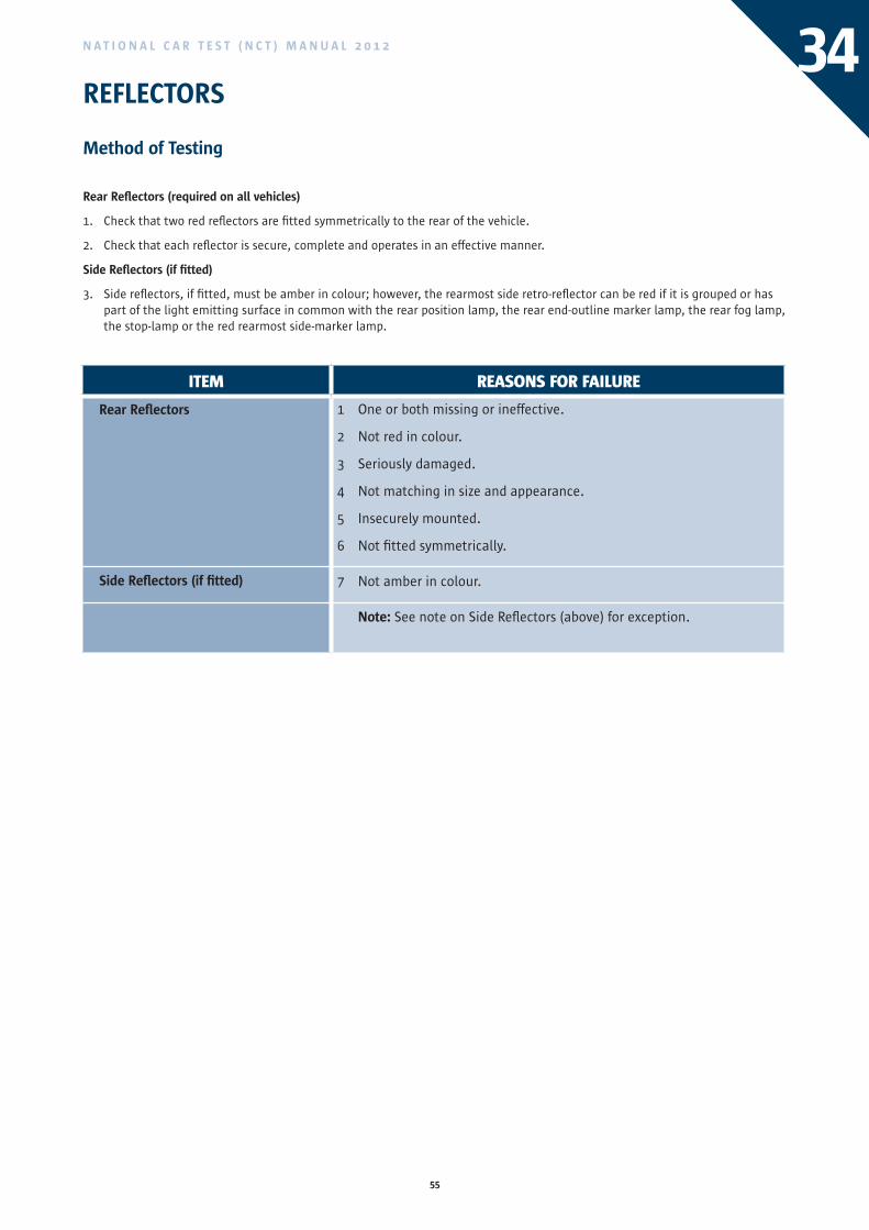
55
N A T I O N A L C A R T E S T ( N C T ) M A N U A L 2 0 1 2
REFLECTORS
Method of Testing
Rear Reflectors (required on all vehicles)
1. Check that two red reflectors are fitted symmetrically to the rear of the vehicle.
2. Check that each reflector is secure, complete and operates in an effective manner.
Side Reflectors (if fitted)
3. Side reflectors, if fitted, must be amber in colour; however, the rearmost side retro-reflector can be red if it is grouped or has part of the light emitting surface in common with the rear position lamp, the rear end-outline marker lamp, the rear fog lamp, the stop-lamp or the red rearmost side-marker lamp.
ITEM REASONS FOR FAILURE
Rear Reflectors
Side Reflectors (if fitted)
1 One or both missing or ineffective.
2 Not red in colour.
3 Seriously damaged.
4 Not matching in size and appearance.
5 Insecurely mounted.
6 Not fitted symmetrically.
7 Not amber in colour.
Note: See note on Side Reflectors (above) for exception.
34
ITEM REASONS FOR FAILURE
Fog Lamp
Auxiliary Lamp(spot or long range lamp)
1 The upper edge of the beam is above the 2% horizontal line.
2 The hot spot centre does not lie below the 0% horizontal line.
3 The centre of the hot spot does not lie between the 0% and 2% vertical lines.
56
N A T I O N A L C A R T E S T ( N C T ) M A N U A L 2 0 1 235BODYWORK
Method of Testing
Examine primary structural components (including floor pan) for cracks, security, damage or rust. Check where repairs have been carried out that there is an engineer’s report stating that the original strength and safety of the vehicle has not been compromised and that any welding or brazing has been carried out using good engineering practice. Check from both front and rear that the body is sitting squarely. Examine all secondary structural components for security, rust or jagged edges. Check that bumpers, guards and body panels are secure and not likely to injure pedestrians or other road users.
Check that fumes are unlikely to enter the vehicle e.g. torn gear lever boots.
Check that the bonnet and boot lid catches are operating properly. In the case of front opening bonnets, ensure that the safety catch is fitted and operating properly.
Primary Structure
1. Primary structure includes any structure or component which, if it collapsed, would make the vehicle uncontrollable or would considerably reduce occupant safety in the event of an accident. Examples of components in this category are illustrated on page 57. Areas within 100mm of door locks or hinges would be considered primary structure.
Secondary Structure
2. Secondary structure includes any structure or component which, if it collapsed, would not immediately affect a vehicle’s controllability or the protection provided by its built-in safety systems. Normally, rust would not be a cause for rejection in these components but extensive rust is usually either hazardous to persons in or near the vehicle because of its sharp edges or because exhaust fumes can get into the vehicle. Extensive rust must therefore be rejected. The illustration on page 57 shows examples of secondary structure.
NOTES
1. A missing or damaged mud flap is not a reason for failure.
2. The judgement to be made is whether or not the manufacturer’s original strength has been maintained. Where a manufacturer has used brazing in some area of the manufacturing process, repairs using a similar process and to a similar standard of workmanship is acceptable. Using brazing to repair chassis members is not acceptable.
3. Where a boot is completely full, an examination cannot be made and therefore a pass certificate cannot be issued.
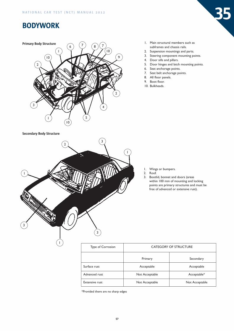
57
N A T I O N A L C A R T E S T ( N C T ) M A N U A L 2 0 1 2
1. Main structural members such assubframes and chassis rails.
2. Suspension mountings and parts.3. Steering component mounting points.4. Door sills and pillars.5. Door hinges and latch mounting points.6. Seat anchorage points.7. Seat belt anchorage points.8. All floor panels.9. Boot floor.10. Bulkheads.
10
16 7 8 7
10
9
2
4
510
1
3
2
23
1
3
1
3
11. Wings or bumpers.2. Roof.3. Bootlid, bonnet and doors (areas
within 100 mm of mounting and lockingpoints are primary structures and must befree of advanced or extensive rust).
ERUTCURTS FO YROGETACnoisorroC fo epyT
yradnoceSyramirP
elbatpeccAelbatpeccAtsur ecafruS
Advanced rust Not Acceptable Acceptable*
elbatpeccA toNelbatpeccA toNtsur evisnetxE
*Provided there are no sharp edges
Primary Body Structure
Secondary Body Structure
35BODYWORK
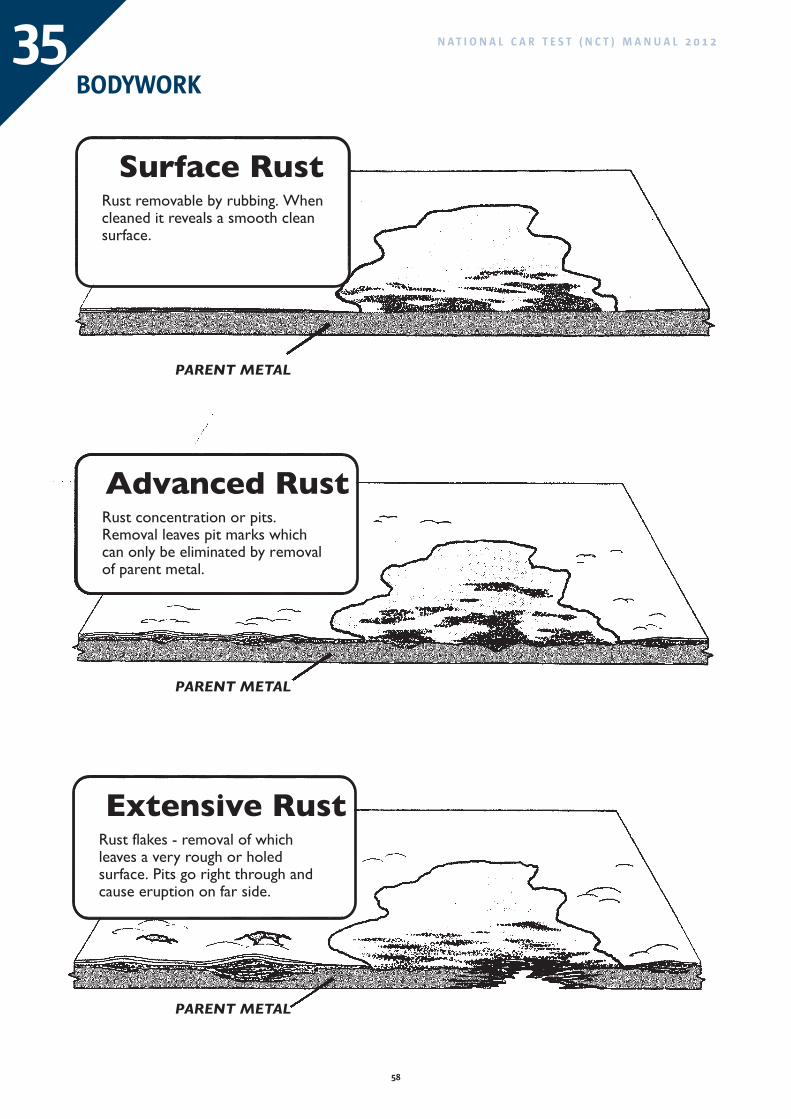
58
N A T I O N A L C A R T E S T ( N C T ) M A N U A L 2 0 1 235BODYWORK
PARENT METAL
Extensive RustRust flakes - removal of whichleaves a very rough or holedsurface. Pits go right through andcause eruption on far side.
PARENT METAL
Advanced RustRust concentration or pits.Removal leaves pit marks whichcan only be eliminated by removalof parent metal.
PARENT METAL
Surface RustRust removable by rubbing. Whencleaned it reveals a smooth cleansurface.
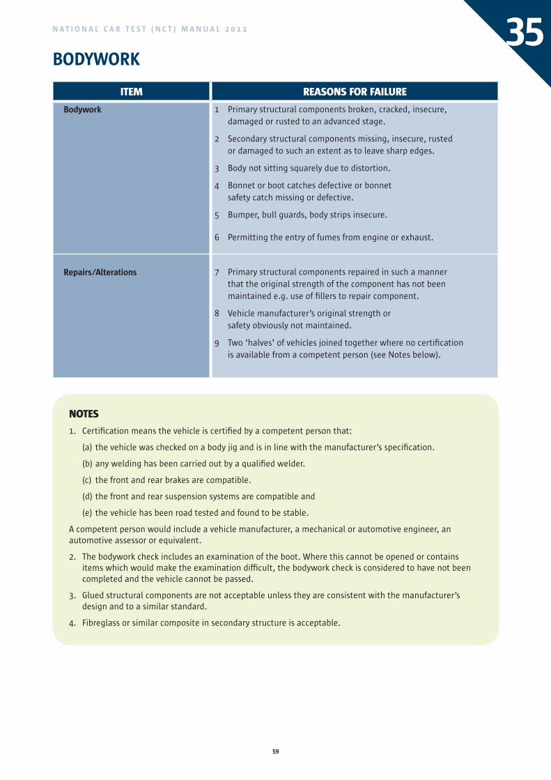
59
N A T I O N A L C A R T E S T ( N C T ) M A N U A L 2 0 1 2
BODYWORK35
ITEM REASONS FOR FAILURE
Bodywork
Repairs/Alterations
1 Primary structural components broken, cracked, insecure, damaged or rusted to an advanced stage.
2 Secondary structural components missing, insecure, rusted or damaged to such an extent as to leave sharp edges.
3 Body not sitting squarely due to distortion.
4 Bonnet or boot catches defective or bonnet safety catch missing or defective.
5 Bumper, bull guards, body strips insecure.
6 Permitting the entry of fumes from engine or exhaust.
7 Primary structural components repaired in such a manner that the original strength of the component has not been maintained e.g. use of fillers to repair component.
8 Vehicle manufacturer’s original strength or safety obviously not maintained.
9 Two ‘halves’ of vehicles joined together where no certification is available from a competent person (see Notes below).
NOTES
1. Certification means the vehicle is certified by a competent person that:
(a) the vehicle was checked on a body jig and is in line with the manufacturer’s specification.
(b) any welding has been carried out by a qualified welder.
(c) the front and rear brakes are compatible.
(d) the front and rear suspension systems are compatible and
(e) the vehicle has been road tested and found to be stable.
A competent person would include a vehicle manufacturer, a mechanical or automotive engineer, an automotive assessor or equivalent.
2. The bodywork check includes an examination of the boot. Where this cannot be opened or contains items which would make the examination difficult, the bodywork check is considered to have not been completed and the vehicle cannot be passed.
3. Glued structural components are not acceptable unless they are consistent with the manufacturer’s design and to a similar standard.
4. Fibreglass or similar composite in secondary structure is acceptable.
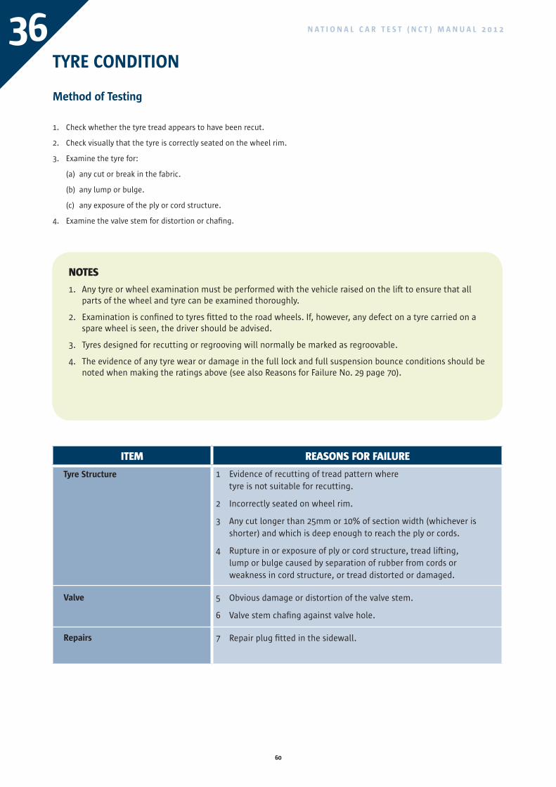
60
N A T I O N A L C A R T E S T ( N C T ) M A N U A L 2 0 1 236TYRE CONDITION
Method of Testing
1. Check whether the tyre tread appears to have been recut.
2. Check visually that the tyre is correctly seated on the wheel rim.
3. Examine the tyre for:
(a) any cut or break in the fabric.
(b) any lump or bulge.
(c) any exposure of the ply or cord structure.
4. Examine the valve stem for distortion or chafing.
NOTES
1. Any tyre or wheel examination must be performed with the vehicle raised on the lift to ensure that all parts of the wheel and tyre can be examined thoroughly.
2. Examination is confined to tyres fitted to the road wheels. If, however, any defect on a tyre carried on a spare wheel is seen, the driver should be advised.
3. Tyres designed for recutting or regrooving will normally be marked as regroovable.
4. The evidence of any tyre wear or damage in the full lock and full suspension bounce conditions should be noted when making the ratings above (see also Reasons for Failure No. 29 page 70).
ITEM REASONS FOR FAILURE
Tyre Structure
Valve
Repairs
1 Evidence of recutting of tread pattern where tyre is not suitable for recutting.
2 Incorrectly seated on wheel rim.
3 Any cut longer than 25mm or 10% of section width (whichever is shorter) and which is deep enough to reach the ply or cords.
4 Rupture in or exposure of ply or cord structure, tread lifting, lump or bulge caused by separation of rubber from cords or weakness in cord structure, or tread distorted or damaged.
5 Obvious damage or distortion of the valve stem.
6 Valve stem chafing against valve hole.
7 Repair plug fitted in the sidewall.
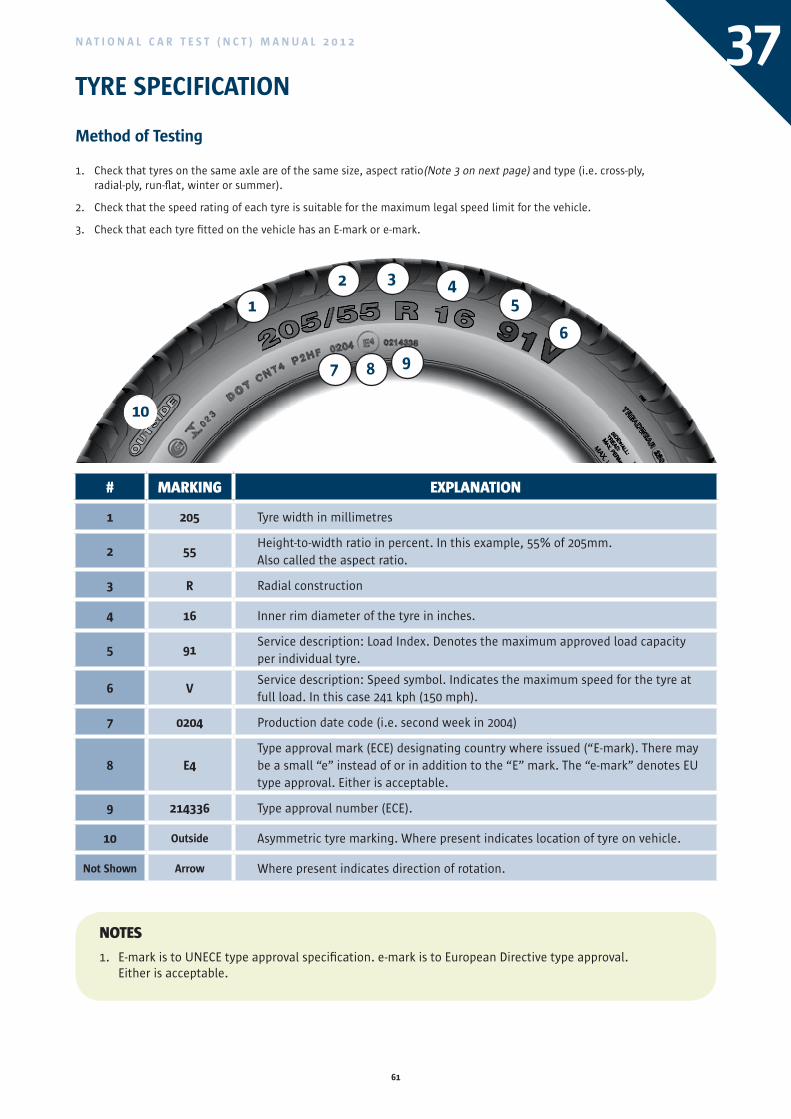
61
N A T I O N A L C A R T E S T ( N C T ) M A N U A L 2 0 1 2
# MARkING ExPLANATION
1 205 Tyre width in millimetres
2 55Height-to-width ratio in percent. In this example, 55% of 205mm. Also called the aspect ratio.
3 R Radial construction
4 16 Inner rim diameter of the tyre in inches.
5 91Service description: Load Index. Denotes the maximum approved load capacityper individual tyre.
6 VService description: Speed symbol. Indicates the maximum speed for the tyre atfull load. In this case 241 kph (150 mph).
7 0204 Production date code (i.e. second week in 2004)
8 E4Type approval mark (ECE) designating country where issued (“E-mark). There maybe a small “e” instead of or in addition to the “E” mark. The “e-mark” denotes EUtype approval. Either is acceptable.
9 214336 Type approval number (ECE).
10 Outside Asymmetric tyre marking. Where present indicates location of tyre on vehicle.
Not Shown Arrow Where present indicates direction of rotation.
37TYRE SPECIFICATION
Method of Testing
1. Check that tyres on the same axle are of the same size, aspect ratio(Note 3 on next page) and type (i.e. cross-ply, radial-ply, run-flat, winter or summer).
2. Check that the speed rating of each tyre is suitable for the maximum legal speed limit for the vehicle.
3. Check that each tyre fitted on the vehicle has an E-mark or e-mark.
NOTES
1. E-mark is to UNECE type approval specification. e-mark is to European Directive type approval. Either is acceptable.
1
2 3 45
6
7 8 9
10
ITEM REASONS FOR FAILURE
Tyre Structure
Valve
Repairs
1 Evidence of recutting of tread pattern where tyre is not suitable for recutting.
2 Incorrectly seated on wheel rim.
3 Any cut longer than 25mm or 10% of section width (whichever is shorter) and which is deep enough to reach the ply or cords.
4 Rupture in or exposure of ply or cord structure, tread lifting, lump or bulge caused by separation of rubber from cords or weakness in cord structure, or tread distorted or damaged.
5 Obvious damage or distortion of the valve stem.
6 Valve stem chafing against valve hole.
7 Repair plug fitted in the sidewall.
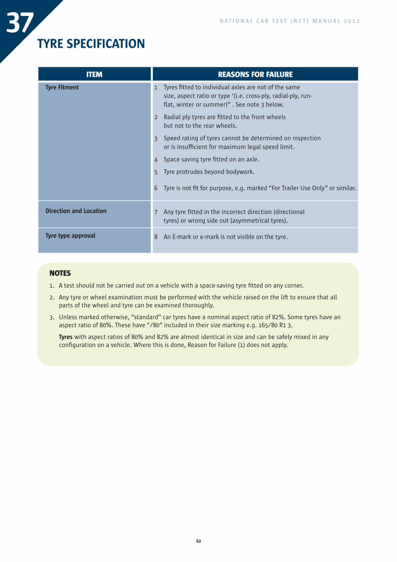
62
N A T I O N A L C A R T E S T ( N C T ) M A N U A L 2 0 1 237
ITEM REASONS FOR FAILURE
Tyre Fitment
Direction and Location Tyre type approval
1 Tyres fitted to individual axles are not of the same size, aspect ratio or type ‘(i.e. cross-ply, radial-ply, run-flat, winter or summer)” . See note 3 below.
2 Radial ply tyres are fitted to the front wheels but not to the rear wheels.
3 Speed rating of tyres cannot be determined on inspection or is insufficient for maximum legal speed limit.
4 Space saving tyre fitted on an axle.
5 Tyre protrudes beyond bodywork.
6 Tyre is not fit for purpose, e.g. marked “For Trailer Use Only” or similar.
7 Any tyre fitted in the incorrect direction (directional tyres) or wrong side out (asymmetrical tyres).
8 An E-mark or e-mark is not visible on the tyre.
TYRE SPECIFICATION
NOTES
1. A test should not be carried out on a vehicle with a space-saving tyre fitted on any corner.
2. Any tyre or wheel examination must be performed with the vehicle raised on the lift to ensure that all parts of the wheel and tyre can be examined thoroughly.
3. Unless marked otherwise, “standard” car tyres have a nominal aspect ratio of 82%. Some tyres have an aspect ratio of 80%. These have “/80” included in their size marking e.g. 165/80 R1 3.
Tyres with aspect ratios of 80% and 82% are almost identical in size and can be safely mixed in any configuration on a vehicle. Where this is done, Reason for Failure (1) does not apply.
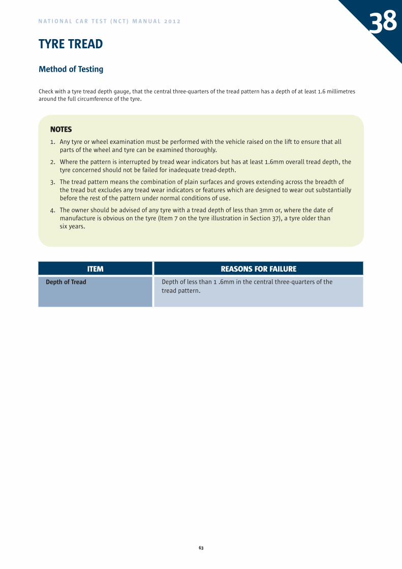
63
N A T I O N A L C A R T E S T ( N C T ) M A N U A L 2 0 1 2 38TYRE TREAD
Method of Testing
Check with a tyre tread depth gauge, that the central three-quarters of the tread pattern has a depth of at least 1.6 millimetres around the full circumference of the tyre.
NOTES
1. Any tyre or wheel examination must be performed with the vehicle raised on the lift to ensure that all parts of the wheel and tyre can be examined thoroughly.
2. Where the pattern is interrupted by tread wear indicators but has at least 1.6mm overall tread depth, the tyre concerned should not be failed for inadequate tread-depth.
3. The tread pattern means the combination of plain surfaces and groves extending across the breadth of the tread but excludes any tread wear indicators or features which are designed to wear out substantially before the rest of the pattern under normal conditions of use.
4. The owner should be advised of any tyre with a tread depth of less than 3mm or, where the date of manufacture is obvious on the tyre (Item 7 on the tyre illustration in Section 37), a tyre older than six years.
ITEM REASONS FOR FAILURE
Depth of Tread Depth of less than 1 .6mm in the central three-quarters of the tread pattern.
ITEM REASONS FOR FAILURE
Tyre Fitment
Direction and Location Tyre type approval
1 Tyres fitted to individual axles are not of the same size, aspect ratio or type ‘(i.e. cross-ply, radial-ply, run-flat, winter or summer)” . See note 3 below.
2 Radial ply tyres are fitted to the front wheels but not to the rear wheels.
3 Speed rating of tyres cannot be determined on inspection or is insufficient for maximum legal speed limit.
4 Space saving tyre fitted on an axle.
5 Tyre protrudes beyond bodywork.
6 Tyre is not fit for purpose, e.g. marked “For Trailer Use Only” or similar.
7 Any tyre fitted in the incorrect direction (directional tyres) or wrong side out (asymmetrical tyres).
8 An E-mark or e-mark is not visible on the tyre.
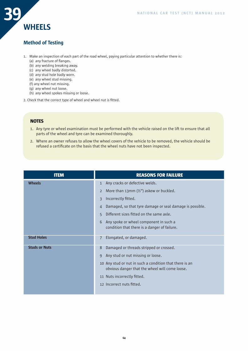
64
N A T I O N A L C A R T E S T ( N C T ) M A N U A L 2 0 1 239WHEELS
Method of Testing
1. Make an inspection of each part of the road wheel, paying particular attention to whether there is:(a) any fracture of flanges.(b) any welding breaking away.(c) any wheel badly distorted.(d) any stud hole badly worn.(e) any wheel stud missing. (f) any wheel nut missing.(g) any wheel nut loose.(h) any wheel spokes missing or loose.
2. Check that the correct type of wheel and wheel nut is fitted.
NOTES
1. Any tyre or wheel examination must be performed with the vehicle raised on the lift to ensure that all parts of the wheel and tyre can be examined thoroughly.
2. Where an owner refuses to allow the wheel covers of the vehicle to be removed, the vehicle should be refused a certificate on the basis that the wheel nuts have not been inspected.
ITEM REASONS FOR FAILURE
Wheels
Stud Holes
Studs or Nuts
1 Any cracks or defective welds.
2 More than 13mm (½”) askew or buckled.
3 Incorrectly fitted.
4 Damaged, so that tyre damage or seal damage is possible.
5 Different sizes fitted on the same axle.
6 Any spoke or wheel component in such a condition that there is a danger of failure.
7 Elongated, or damaged.
8 Damaged or threads stripped or crossed.
9 Any stud or nut missing or loose.
10 Any stud or nut in such a condition that there is an obvious danger that the wheel will come loose.
11 Nuts incorrectly fitted.
12 Incorrect nuts fitted.
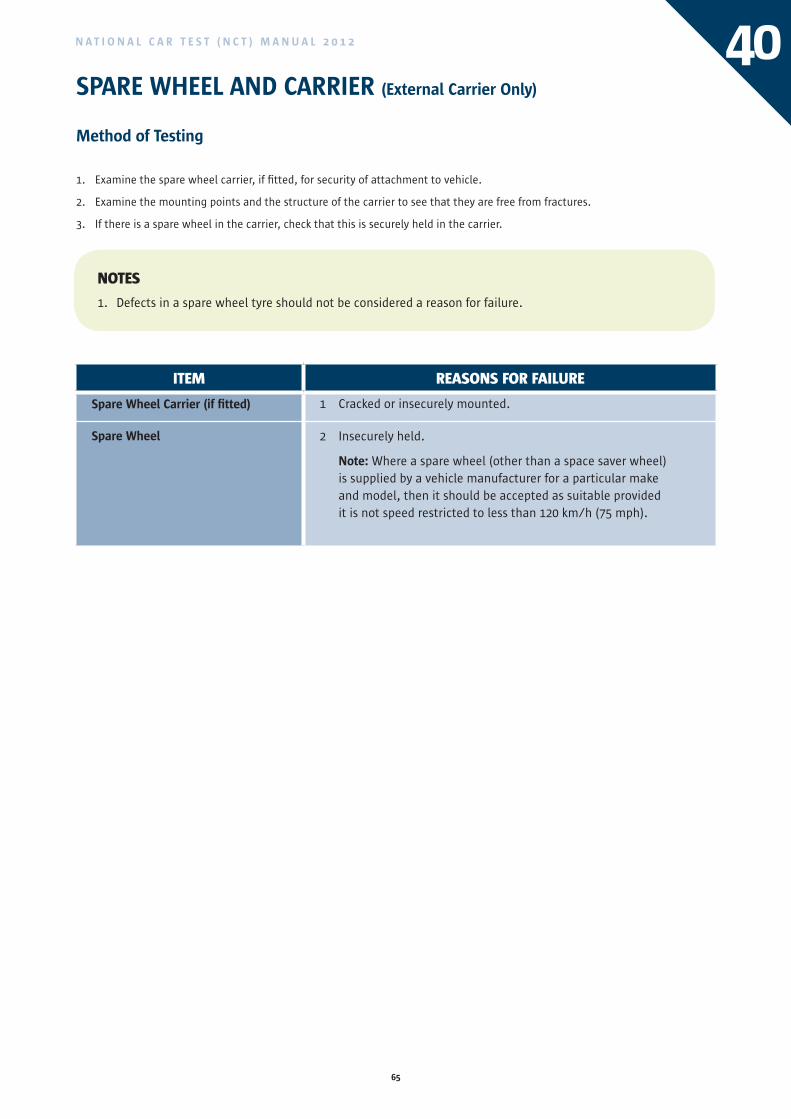
65
N A T I O N A L C A R T E S T ( N C T ) M A N U A L 2 0 1 2 40SPARE WHEEL AND CARRIER (External Carrier Only)
Method of Testing
1. Examine the spare wheel carrier, if fitted, for security of attachment to vehicle.
2. Examine the mounting points and the structure of the carrier to see that they are free from fractures.
3. If there is a spare wheel in the carrier, check that this is securely held in the carrier.
NOTES
1. Defects in a spare wheel tyre should not be considered a reason for failure.
ITEM REASONS FOR FAILURE
Spare Wheel Carrier (if fitted)
Spare Wheel
1 Cracked or insecurely mounted.
2 Insecurely held.
Note: Where a spare wheel (other than a space saver wheel) is supplied by a vehicle manufacturer for a particular make and model, then it should be accepted as suitable provided it is not speed restricted to less than 120 km/h (75 mph).
ITEM REASONS FOR FAILURE
Wheels
Stud Holes
Studs or Nuts
1 Any cracks or defective welds.
2 More than 13mm (½”) askew or buckled.
3 Incorrectly fitted.
4 Damaged, so that tyre damage or seal damage is possible.
5 Different sizes fitted on the same axle.
6 Any spoke or wheel component in such a condition that there is a danger of failure.
7 Elongated, or damaged.
8 Damaged or threads stripped or crossed.
9 Any stud or nut missing or loose.
10 Any stud or nut in such a condition that there is an obvious danger that the wheel will come loose.
11 Nuts incorrectly fitted.
12 Incorrect nuts fitted.
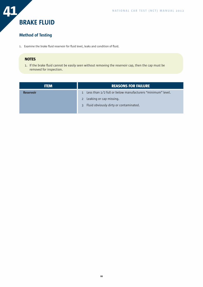
66
N A T I O N A L C A R T E S T ( N C T ) M A N U A L 2 0 1 241BRAKE FLUID
Method of Testing
1. Examine the brake fluid reservoir for fluid level, leaks and condition of fluid.
NOTES
1. If the brake fluid cannot be easily seen without removing the reservoir cap, then the cap must be removed for inspection.
ITEM REASONS FOR FAILURE
Reservoir 1 Less than 1⁄2 full or below manufacturers “minimum” level.
2 Leaking or cap missing.
3 Fluid obviously dirty or contaminated.
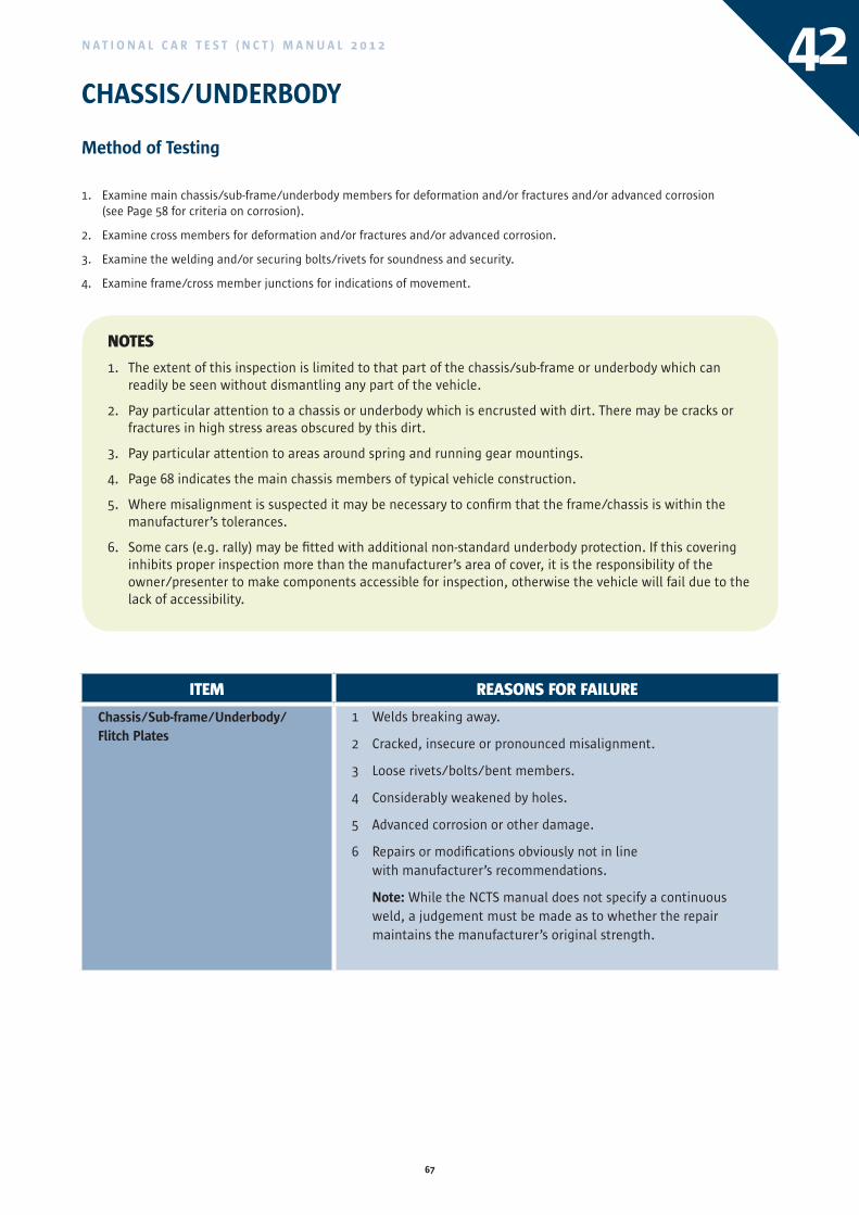
67
N A T I O N A L C A R T E S T ( N C T ) M A N U A L 2 0 1 2 42CHASSIS/UNDERBODY
Method of Testing
1. Examine main chassis/sub-frame/underbody members for deformation and/or fractures and/or advanced corrosion (see Page 58 for criteria on corrosion).
2. Examine cross members for deformation and/or fractures and/or advanced corrosion.
3. Examine the welding and/or securing bolts/rivets for soundness and security.
4. Examine frame/cross member junctions for indications of movement.
ITEM REASONS FOR FAILURE
Chassis/Sub-frame/Underbody/Flitch Plates
1 Welds breaking away.
2 Cracked, insecure or pronounced misalignment.
3 Loose rivets/bolts/bent members.
4 Considerably weakened by holes.
5 Advanced corrosion or other damage.
6 Repairs or modifications obviously not in line with manufacturer’s recommendations.
Note: While the NCTS manual does not specify a continuous weld, a judgement must be made as to whether the repair maintains the manufacturer’s original strength.
NOTES
1. The extent of this inspection is limited to that part of the chassis/sub-frame or underbody which can readily be seen without dismantling any part of the vehicle.
2. Pay particular attention to a chassis or underbody which is encrusted with dirt. There may be cracks or fractures in high stress areas obscured by this dirt.
3. Pay particular attention to areas around spring and running gear mountings.
4. Page 68 indicates the main chassis members of typical vehicle construction.
5. Where misalignment is suspected it may be necessary to confirm that the frame/chassis is within the manufacturer’s tolerances.
6. Some cars (e.g. rally) may be fitted with additional non-standard underbody protection. If this covering inhibits proper inspection more than the manufacturer’s area of cover, it is the responsibility of the owner/presenter to make components accessible for inspection, otherwise the vehicle will fail due to the lack of accessibility.
ITEM REASONS FOR FAILURE
Reservoir 1 Less than 1⁄2 full or below manufacturers “minimum” level.
2 Leaking or cap missing.
3 Fluid obviously dirty or contaminated.
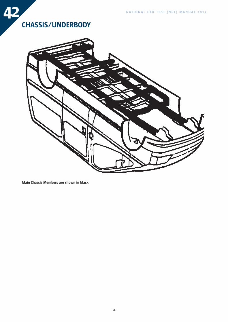
68
N A T I O N A L C A R T E S T ( N C T ) M A N U A L 2 0 1 242CHASSIS/UNDERBODY
Main Chassis Members are shown in black.
69
N A T I O N A L C A R T E S T ( N C T ) M A N U A L 2 0 1 2 43STEERING LINKAGE
Method of Testing
1. With the road wheels on the ground and the steering wheel rotated clockwise and anti-clockwise against the road resistance, examine the steering mechanism from the point where it is secured to the chassis to the point where the steering arms are secured to their fixings. For vehicles fitted with power steering, it may be necessary to have the engine running.
During this inspection check for:
(a) excessive wear at joints.
(b) fracture of or damage to components.
(c) insecure components.
2. With steered wheels off the ground (using the vehicle manufacturer’s recommended jacking points):
(a) check for fouling of wheels, tyres and components of the steering linkage with any part of the vehicle by rotating the steering wheel through its full working range and also by examining likely fouling points for abrasion.
(b) while the steering wheel is being rotated, also check the steering column shaft and steering box/rack for stiffness or worn or damaged bearings.
(c) note the amount of movement between the axle beam and the stub axle whilst each wheel in turn is rocked. Alternatively a wheel play detector device may be used.
(d) note the amount of upward movement of the stub axle, whilst each wheel in turn is lifted with a bar placed underneath it.
(e) examine visible parts of the stub axle for condition and security.
(f) where possible, examine the king pin retaining device.
3. For Integral Power Steering; Check by the feel on the steering wheel that the power steering is operating by rocking the steering wheel with the engine running and the road wheels on the ground.
NOTES
1. All steered axles are to be examined.
2. If power steering is optional on the vehicle type concerned, and is fitted to the particular vehicle but has been disconnected in such a way that it can have no adverse effect on the manual steering, this should not be regarded as a defect.
3. Welding of steering parts other than by a manufacturer is not acceptable.
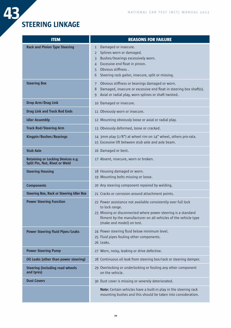
70
N A T I O N A L C A R T E S T ( N C T ) M A N U A L 2 0 1 243STEERING LINKAGE
ITEM REASONS FOR FAILURE
Rack and Pinion Type Steering
Steering Box
Drop Arm/Drag Link
Drag Link and Track Rod Ends
Idler Assembly
Track Rod/Steering Arm
Kingpin/Bushes/Bearings
Stub Axle
Retaining or Locking Devices e.g.Split Pin, Nut, Rivet or Weld
Steering Housing
Components
Steering Box, Rack or Steering Idler Box
Power Steering Function
Power Steering Fluid Pipes/Leaks
Power Steering Pump
Oil Leaks (other than power steering)
Steering (including road wheelsand tyres)
Dust Covers
1 Damaged or insecure.
2 Splines worn or damaged.
3 Bushes/bearings excessively worn.
4 Excessive end float in pinion.
5 Obvious stiffness .
6 Steering rack gaiter, insecure, split or missing.
7 Obvious stiffness or bearings damaged or worn.
8 Damaged, insecure or excessive end float in steering box shaft(s).
9 Axial or radial play, worn splines or shaft twisted.
10 Damaged or insecure.
11 Obviously worn or insecure.
12 Mounting obviously loose or axial or radial play.
13 Obviously deformed, loose or cracked.
14 3mm play (1/8”) at wheel rim on 14” wheel, others pro-rata.
15 Excessive lift between stub axle and axle beam.
16 Damaged or bent.
17 Absent, insecure, worn or broken.
18 Housing damaged or worn.
19 Mounting bolts missing or loose.
20 Any steering component repaired by welding.
21 Cracks or corrosion around attachment points.
22 Power assistance not available consistently over full lock to lock range.
23 Missing or disconnected where power steering is a standard fitment by the manufacturer on all vehicles of the vehicle type (make and model) on test.
24 Power steering fluid below minimum level.
25 Fluid pipes fouling other components.
26 Leaks.
27 Worn, noisy, leaking or drive defective.
28 Continuous oil leak from steering box/rack or steering damper.
29 Overlocking or underlocking or fouling any other component on the vehicle.
30 Dust cover is missing or severely deteriorated.
Note: Certain vehicles have a built-in play in the steering rack mounting bushes and this should be taken into consideration.
71
N A T I O N A L C A R T E S T ( N C T ) M A N U A L 2 0 1 2 44WHEEL BEARINGS
Method of Testing
APPLIES TO ALL ROAD WHEELS
Raise the axle(s) of the wheels being examined so that they are clear of the ground.
1. Note the movement of the wheel relative to the axle or stub axle in order to assess the play in the wheel bearings, whilst each wheel in turn is rocked.
2. Spin each wheel rapidly and listen for any roughness or harshness in the bearings.
3. The vehicle should be failed if a distinctive rumble or growl is heard that indicates the bearing is worn or damaged.
ITEM REASONS FOR FAILURE
Wheel Bearings or Hub 1 Obviously too much play.
2 Too tight.
3 Bearings or hub are worn or damaged.
ITEM REASONS FOR FAILURE
Rack and Pinion Type Steering
Steering Box
Drop Arm/Drag Link
Drag Link and Track Rod Ends
Idler Assembly
Track Rod/Steering Arm
Kingpin/Bushes/Bearings
Stub Axle
Retaining or Locking Devices e.g.Split Pin, Nut, Rivet or Weld
Steering Housing
Components
Steering Box, Rack or Steering Idler Box
Power Steering Function
Power Steering Fluid Pipes/Leaks
Power Steering Pump
Oil Leaks (other than power steering)
Steering (including road wheelsand tyres)
Dust Covers
1 Damaged or insecure.
2 Splines worn or damaged.
3 Bushes/bearings excessively worn.
4 Excessive end float in pinion.
5 Obvious stiffness .
6 Steering rack gaiter, insecure, split or missing.
7 Obvious stiffness or bearings damaged or worn.
8 Damaged, insecure or excessive end float in steering box shaft(s).
9 Axial or radial play, worn splines or shaft twisted.
10 Damaged or insecure.
11 Obviously worn or insecure.
12 Mounting obviously loose or axial or radial play.
13 Obviously deformed, loose or cracked.
14 3mm play (1/8”) at wheel rim on 14” wheel, others pro-rata.
15 Excessive lift between stub axle and axle beam.
16 Damaged or bent.
17 Absent, insecure, worn or broken.
18 Housing damaged or worn.
19 Mounting bolts missing or loose.
20 Any steering component repaired by welding.
21 Cracks or corrosion around attachment points.
22 Power assistance not available consistently over full lock to lock range.
23 Missing or disconnected where power steering is a standard fitment by the manufacturer on all vehicles of the vehicle type (make and model) on test.
24 Power steering fluid below minimum level.
25 Fluid pipes fouling other components.
26 Leaks.
27 Worn, noisy, leaking or drive defective.
28 Continuous oil leak from steering box/rack or steering damper.
29 Overlocking or underlocking or fouling any other component on the vehicle.
30 Dust cover is missing or severely deteriorated.
Note: Certain vehicles have a built-in play in the steering rack mounting bushes and this should be taken into consideration.
72
N A T I O N A L C A R T E S T ( N C T ) M A N U A L 2 0 1 245FRONT SPRINGS
Method of Testing
Leaf Springs
1. Examine each spring for its general condition and in particular for fractures in the leaves, especially in the vicinity of the anchor eye of the main leaf.
2. Note whether any spring is so weak that it is not holding the body sufficiently far away from the wheels.
3. Examine condition of spring eyes/bushes.
4. Check that no spring clamps are missing.
5. Check that the springs on each axle are symmetrically located.
6. Check that there is no movement of spring leaves denoting a fractured centre bolt.
7. Check that the attachments of the shackle/anchor brackets to the chassis are secure, looking for signs of movement of rivets or bolts, and elongated holes.
8. Examine the bolts and/or nuts securing the spring to the axle for tightness, and examine the spring and axle for evidence that these have been moving relative to each other.
Coil Springs
9. Examine each spring for its general condition and in particular for fractures.
10. Note whether any spring is so weak that it is not holding the body sufficiently far away from the wheels.
11. Examine the attachment of the coil springs for security.
Torsion Bars
12. Check torsion bars for fracture or damage.
13. Examine the attachment of the torsion bars.
Spring Pins and Bushes
14. Examine the amount of play due to wear at spring anchor brackets and pins of the spring shackles.
15. Examine the condition and security of any slipper brackets.
16. Check that the anchor/shackle pins are fully in place, that they are secure and that locking devices are in position and secure.
17. Examine the spring mountings for excessive side play.
Air and Fluid Suspension
18. Check for leaks and the condition of the supply lines and suspension bellows.
19. Check the condition of levelling valve linkages.
20. Examine the attachment of the suspension bellows for security.
21. Examine the attachments for security to frame and axle.
Bonded Suspension Units
22. Examine the bonding of the flexible element to its associated metal fixings.
23. Examine the condition of the flexible element by applying pressure.
24. Examine the attachments for security to frame and axle.
NOTES
1. A bush and/or pin would be considered excessively worn if wear exceeded 2mm (3⁄32”) for 13mm (1⁄2”) diameter pins, others pro rata.
2. Caution should be exercised in the case of springs and suspensions with rubber/compliant mountings where the amount of free movement in new components might well exceed the above limit. In such cases the manufacturer’s tolerances should be sought. Observation of the vehicle attitude when stationary can often reveal the effect of exhausted or broken springs, e.g. vehicle “sitting down” at front.
73
N A T I O N A L C A R T E S T ( N C T ) M A N U A L 2 0 1 2 45FRONT SPRINGS
ITEM REASONS FOR FAILURE
Spring (coil/leaf)/Torsion Bar
Spring Mounting or Torsion BarMounting
Spring Eye-bolt/Shackle Pins
Spring or Shackle Bushes
Spring Centre Bolt
Bump Stop
Air, Hydrolastic,Hydrogas, Suspension
Bonded Suspension Units
1 Worn or exhausted.
2 Any spring leaf broken, repaired by welding or missing.
3 Spring fitted incorrectly.
4 Spring clamps missing.
5 U-bolts loose or missing.
6 A coil spring or torsion bar broken.
7 Obviously loose/broken.
8 Cracked or damaged.
9 Locking device missing or insecurely fitted.
10 Worn, incorrectly positioned, incorrect type, or missing.
11 Obviously loose in the bush.
12 Worn, missing or perished.
13 Missing damaged or broken.
14 Missing or ineffective.
15 Leaks.
16 Linkage to levelling valve defective.
17 Valves insecure or defective.
18 Suspension bellows giving inadequate movement (risk of wheel fouling).
19 Pipe damaged to the extent that it is likely to fail.
20 Vehicle sitting on bump stops.
21 Failure of rubber/metal attachment.
22 Deterioration of suspension medium (soft and sticky).
74
N A T I O N A L C A R T E S T ( N C T ) M A N U A L 2 0 1 246FRONT SUSPENSION
Method of Testing
1. With the vehicle on the lift or pit, jack up the vehicle using the vehicle manufacturer’s recommended jacking points for checking the front suspension. Where this is not available, see 2, 3 and 4 below.
2. For suspension of the type shown in figure 1, jack up the front suspension so that the road-wheels are clear of the ground and the suspension is as near as possible to normal running height. Whilst each wheel is held at the top and bottom and rocked, examine for movement in the top and bottom ball joints and movement in the wishbone bushes.
3. For suspensions of the type shown in figure 2 and 3, jack up the front suspension so that the road wheels are clear of the ground and shake each road-wheel vigorously to determine the condition of the outer suspension ball joints and movement in the control arms.
4. For suspension of the type shown in figure 4, jack up the front suspension so that the road-wheels are clear of the ground. Shake each wheel vigorously and examine each suspension strut for wear at the strut sliding bush and gland as well as for movement at the strut upper support bearing and:
(a) check for damage or excessive corrosion of the strut casing, wear in the rod and the condition of the bonding between the metal and flexible material in the strut upper support bearing.
(b) whilst each front wheel is shaken vigorously (grasping at the 3 o’clock and 9 o’clock positions), check the condition of the outer ball joints and track control arm inner bushes for movement indicating the degree of wear.
5. For all suspension types, examine:
(a) the condition of wishbones and their inner bearings, ball joints, swivel joints, track control arms, anti-roll bars, radius rods and their mounting bushes or washers.
(b) examine axle beams, leading arms and swinging arms for damage or distortion.
(c) examine the condition of the chassis frame and body shell structure in the vicinity of suspension mounting points and suspension sub-frame mounting points for fractures, excessive corrosion or distortion (see page 58).
ITEM REASONS FOR FAILURE
Axle BeamWishbones, Swinging arm,Track Control Arm, Suspension Strut
Anti-roll Bar, Torque Arm/Rod, Radius Rod/Link
Bushes, Ball Joints, and Sliding Bushes or Swivel Joints
Suspension Mounting Area
Retaining or Locking Devices e.g. Split Pin, Nut, Rivet or Weld.
Dust Covers
1 Obviously out of line.
2 Mounting obviously loose or worn.
3 Cracked, damaged or deformed.
4 Missing or broken.
5 Mounting loose.
6 Cracked, damaged or deformed.
7 Excessive wear.
8 Insecure.
9 Deformed or corroded to such an extent that the security or alignment of the suspension component is affected.
10 Absent, insecure, worn or broken.
11 Dust cover is missing or severely deteriorated.
Note: The above defects may be present in both rigid axle and independent suspension systems.
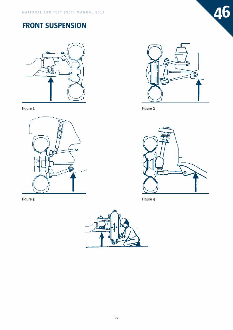
75
N A T I O N A L C A R T E S T ( N C T ) M A N U A L 2 0 1 2 46FRONT SUSPENSION
Figure 1
Figure 3
Figure 2
Figure 4
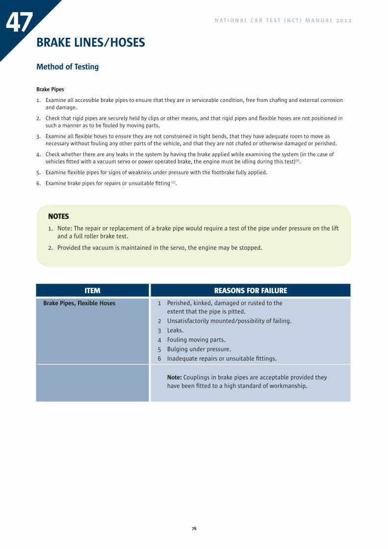
76
N A T I O N A L C A R T E S T ( N C T ) M A N U A L 2 0 1 247BRAKE LINES/HOSES
Method of Testing
Brake Pipes
1. Examine all accessible brake pipes to ensure that they are in serviceable condition, free from chafing and external corrosion and damage.
2. Check that rigid pipes are securely held by clips or other means, and that rigid pipes and flexible hoses are not positioned in such a manner as to be fouled by moving parts.
3. Examine all flexible hoses to ensure they are not constrained in tight bends, that they have adequate room to move as necessary without fouling any other parts of the vehicle, and that they are not chafed or otherwise damaged or perished.
4. Check whether there are any leaks in the system by having the brake applied while examining the system (in the case of vehicles fitted with a vacuum servo or power operated brake, the engine must be idling during this test)(2).
5. Examine flexible pipes for signs of weakness under pressure with the footbrake fully applied.
6. Examine brake pipes for repairs or unsuitable fitting (1).
ITEM REASONS FOR FAILURE
Brake Pipes, Flexible Hoses 1 Perished, kinked, damaged or rusted to the extent that the pipe is pitted.
2 Unsatisfactorily mounted/possibility of failing.
3 Leaks.
4 Fouling moving parts.
5 Bulging under pressure.
6 Inadequate repairs or unsuitable fittings.
Note: Couplings in brake pipes are acceptable provided they have been fitted to a high standard of workmanship.
NOTES
1. Note: The repair or replacement of a brake pipe would require a test of the pipe under pressure on the lift and a full roller brake test.
2. Provided the vacuum is maintained in the servo, the engine may be stopped.
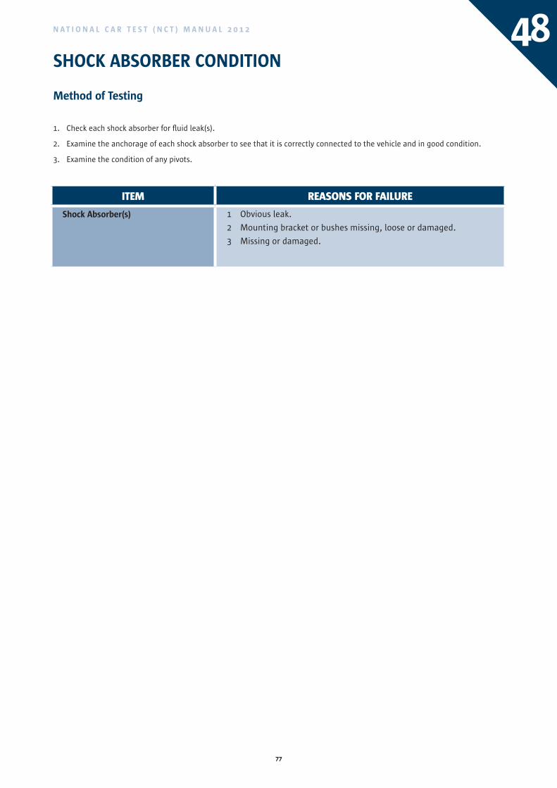
77
N A T I O N A L C A R T E S T ( N C T ) M A N U A L 2 0 1 2
SHOCK ABSORBER CONDITION
Method of Testing
1. Check each shock absorber for fluid leak(s).
2. Examine the anchorage of each shock absorber to see that it is correctly connected to the vehicle and in good condition.
3. Examine the condition of any pivots.
48
ITEM REASONS FOR FAILURE
Shock Absorber(s) 1 Obvious leak.
2 Mounting bracket or bushes missing, loose or damaged.
3 Missing or damaged.
ITEM REASONS FOR FAILURE
Brake Pipes, Flexible Hoses 1 Perished, kinked, damaged or rusted to the extent that the pipe is pitted.
2 Unsatisfactorily mounted/possibility of failing.
3 Leaks.
4 Fouling moving parts.
5 Bulging under pressure.
6 Inadequate repairs or unsuitable fittings.
Note: Couplings in brake pipes are acceptable provided they have been fitted to a high standard of workmanship.
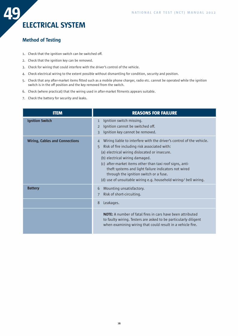
78
N A T I O N A L C A R T E S T ( N C T ) M A N U A L 2 0 1 249ELECTRICAL SYSTEM
Method of Testing
1. Check that the ignition switch can be switched off.
2. Check that the ignition key can be removed.
3. Check for wiring that could interfere with the driver’s control of the vehicle.
4. Check electrical wiring to the extent possible without dismantling for condition, security and position.
5. Check that any after-market items fitted such as a mobile phone charger, radio etc. cannot be operated while the ignition switch is in the off position and the key removed from the switch.
6. Check (where practical) that the wiring used in after-market fitments appears suitable.
7. Check the battery for security and leaks.
ITEM REASONS FOR FAILURE
Ignition Switch
Wiring, Cables and Connections
Battery
1 Ignition switch missing.
2 Ignition cannot be switched off.
3 Ignition key cannot be removed.
4 Wiring liable to interfere with the driver’s control of the vehicle.
5 Risk of fire including risk associated with:
(a) electrical wiring dislocated or insecure.
(b) electrical wiring damaged.
(c) after-market items other than taxi roof signs, anti-theft systems and light failure indicators not wired through the ignition switch or a fuse.
(d) use of unsuitable wiring e.g. household wiring/ bell wiring.
6 Mounting unsatisfactory.
7 Risk of short-circuiting.
8 Leakages.
NOTE: A number of fatal fires in cars have been attributed to faulty wiring. Testers are asked to be particularly diligent when examining wiring that could result in a vehicle fire.
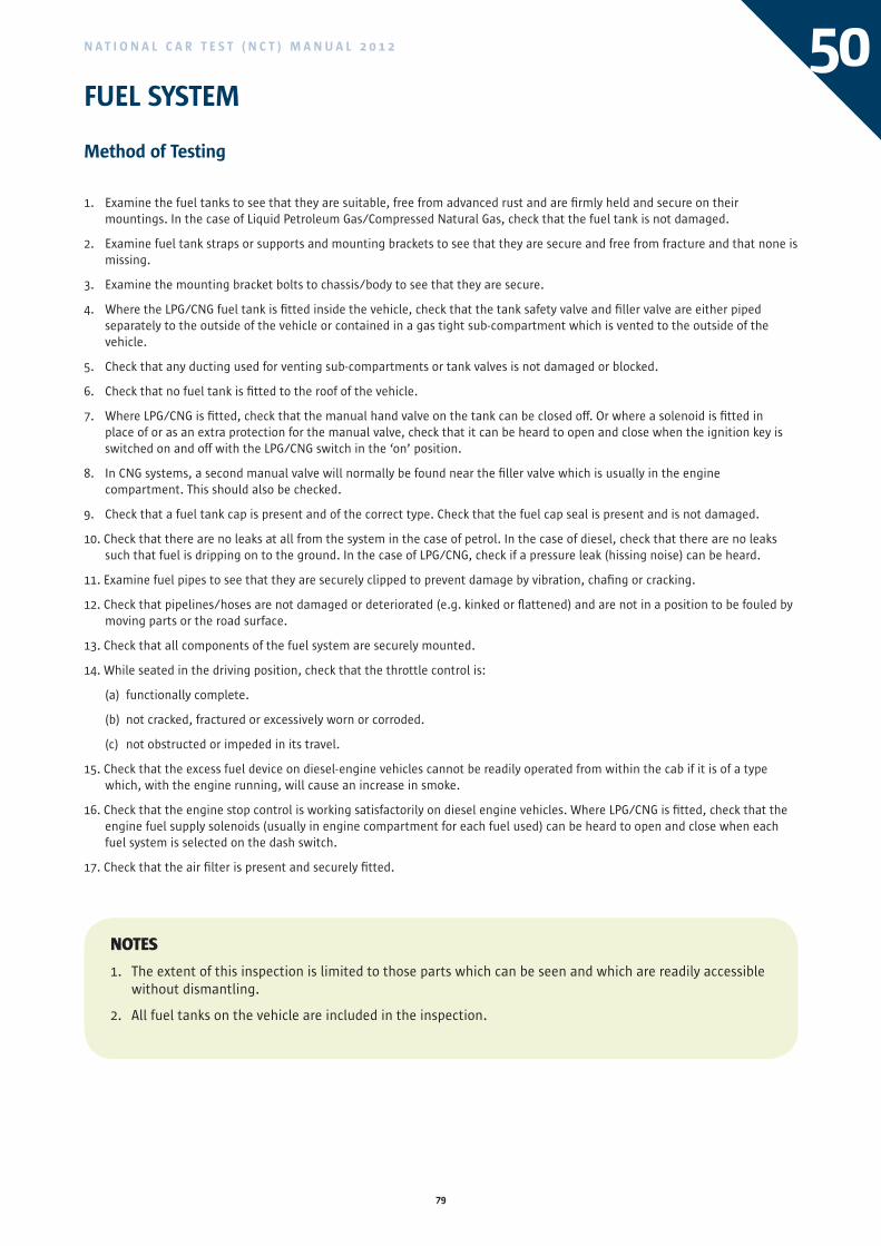
79
N A T I O N A L C A R T E S T ( N C T ) M A N U A L 2 0 1 2 50FUEL SYSTEM
Method of Testing
1. Examine the fuel tanks to see that they are suitable, free from advanced rust and are firmly held and secure on their mountings. In the case of Liquid Petroleum Gas/Compressed Natural Gas, check that the fuel tank is not damaged.
2. Examine fuel tank straps or supports and mounting brackets to see that they are secure and free from fracture and that none is missing.
3. Examine the mounting bracket bolts to chassis/body to see that they are secure.
4. Where the LPG/CNG fuel tank is fitted inside the vehicle, check that the tank safety valve and filler valve are either piped separately to the outside of the vehicle or contained in a gas tight sub-compartment which is vented to the outside of the vehicle.
5. Check that any ducting used for venting sub-compartments or tank valves is not damaged or blocked.
6. Check that no fuel tank is fitted to the roof of the vehicle.
7. Where LPG/CNG is fitted, check that the manual hand valve on the tank can be closed off. Or where a solenoid is fitted in place of or as an extra protection for the manual valve, check that it can be heard to open and close when the ignition key is switched on and off with the LPG/CNG switch in the ‘on’ position.
8. In CNG systems, a second manual valve will normally be found near the filler valve which is usually in the engine compartment. This should also be checked.
9. Check that a fuel tank cap is present and of the correct type. Check that the fuel cap seal is present and is not damaged.
10. Check that there are no leaks at all from the system in the case of petrol. In the case of diesel, check that there are no leaks such that fuel is dripping on to the ground. In the case of LPG/CNG, check if a pressure leak (hissing noise) can be heard.
11. Examine fuel pipes to see that they are securely clipped to prevent damage by vibration, chafing or cracking.
12. Check that pipelines/hoses are not damaged or deteriorated (e.g. kinked or flattened) and are not in a position to be fouled by moving parts or the road surface.
13. Check that all components of the fuel system are securely mounted.
14. While seated in the driving position, check that the throttle control is:
(a) functionally complete.
(b) not cracked, fractured or excessively worn or corroded.
(c) not obstructed or impeded in its travel.
15. Check that the excess fuel device on diesel-engine vehicles cannot be readily operated from within the cab if it is of a type which, with the engine running, will cause an increase in smoke.
16. Check that the engine stop control is working satisfactorily on diesel engine vehicles. Where LPG/CNG is fitted, check that the engine fuel supply solenoids (usually in engine compartment for each fuel used) can be heard to open and close when each fuel system is selected on the dash switch.
17. Check that the air filter is present and securely fitted.
NOTES
1. The extent of this inspection is limited to those parts which can be seen and which are readily accessible without dismantling.
2. All fuel tanks on the vehicle are included in the inspection.
ITEM REASONS FOR FAILURE
Ignition Switch
Wiring, Cables and Connections
Battery
1 Ignition switch missing.
2 Ignition cannot be switched off.
3 Ignition key cannot be removed.
4 Wiring liable to interfere with the driver’s control of the vehicle.
5 Risk of fire including risk associated with:
(a) electrical wiring dislocated or insecure.
(b) electrical wiring damaged.
(c) after-market items other than taxi roof signs, anti-theft systems and light failure indicators not wired through the ignition switch or a fuse.
(d) use of unsuitable wiring e.g. household wiring/ bell wiring.
6 Mounting unsatisfactory.
7 Risk of short-circuiting.
8 Leakages.
NOTE: A number of fatal fires in cars have been attributed to faulty wiring. Testers are asked to be particularly diligent when examining wiring that could result in a vehicle fire.
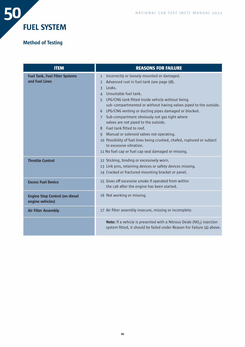
80
N A T I O N A L C A R T E S T ( N C T ) M A N U A L 2 0 1 250
ITEM REASONS FOR FAILURE
Fuel Tank, Fuel Filter Systemsand Fuel Lines
Throttle Control
Excess Fuel Device
Engine Stop Control (on diesel engine vehicles)
Air Filter Assembly
1 Incorrectly or loosely mounted or damaged.
2 Advanced rust in fuel tank (see page 58).
3 Leaks.
4 Unsuitable fuel tank.
5 LPG/CNG tank fitted inside vehicle without being sub- compartmented or without having valves piped to the outside.
6 LPG/CNG venting or ducting pipes damaged or blocked.
7 Sub-compartment obviously not gas tight where valves are not piped to the outside.
8 Fuel tank fitted to roof.
9 Manual or solenoid valves not operating.
10 Possibility of fuel lines being crushed, chafed, ruptured or subject to excessive vibration.
11 No fuel cap or fuel cap seal damaged or missing.
12 Sticking, binding or excessively worn.
13 Link pins, retaining devices or safety devices missing.
14 Cracked or fractured mounting bracket or panel.
15 Gives off excessive smoke if operated from within the cab after the engine has been started.
16 Not working or missing.
17 Air filter assembly insecure, missing or incomplete.
Note: If a vehicle is presented with a Nitrous Oxide (NO2) injection system fitted, it should be failed under Reason For Failure (4) above.
FUEL SYSTEM
Method of Testing
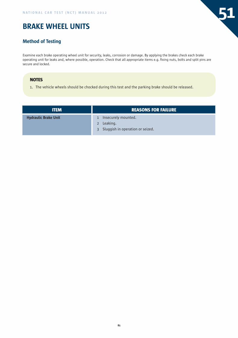
81
N A T I O N A L C A R T E S T ( N C T ) M A N U A L 2 0 1 2 51BRAKE WHEEL UNITS
Method of Testing
Examine each brake operating wheel unit for security, leaks, corrosion or damage. By applying the brakes check each brake operating unit for leaks and, where possible, operation. Check that all appropriate items e.g. fixing nuts, bolts and split pins are secure and locked.
ITEM REASONS FOR FAILURE
Hydraulic Brake Unit 1 Insecurely mounted.
2 Leaking.
3 Sluggish in operation or seized.
NOTES
1. The vehicle wheels should be chocked during this test and the parking brake should be released.
ITEM REASONS FOR FAILURE
Fuel Tank, Fuel Filter Systemsand Fuel Lines
Throttle Control
Excess Fuel Device
Engine Stop Control (on diesel engine vehicles)
Air Filter Assembly
1 Incorrectly or loosely mounted or damaged.
2 Advanced rust in fuel tank (see page 58).
3 Leaks.
4 Unsuitable fuel tank.
5 LPG/CNG tank fitted inside vehicle without being sub- compartmented or without having valves piped to the outside.
6 LPG/CNG venting or ducting pipes damaged or blocked.
7 Sub-compartment obviously not gas tight where valves are not piped to the outside.
8 Fuel tank fitted to roof.
9 Manual or solenoid valves not operating.
10 Possibility of fuel lines being crushed, chafed, ruptured or subject to excessive vibration.
11 No fuel cap or fuel cap seal damaged or missing.
12 Sticking, binding or excessively worn.
13 Link pins, retaining devices or safety devices missing.
14 Cracked or fractured mounting bracket or panel.
15 Gives off excessive smoke if operated from within the cab after the engine has been started.
16 Not working or missing.
17 Air filter assembly insecure, missing or incomplete.
Note: If a vehicle is presented with a Nitrous Oxide (NO2) injection system fitted, it should be failed under Reason For Failure (4) above.
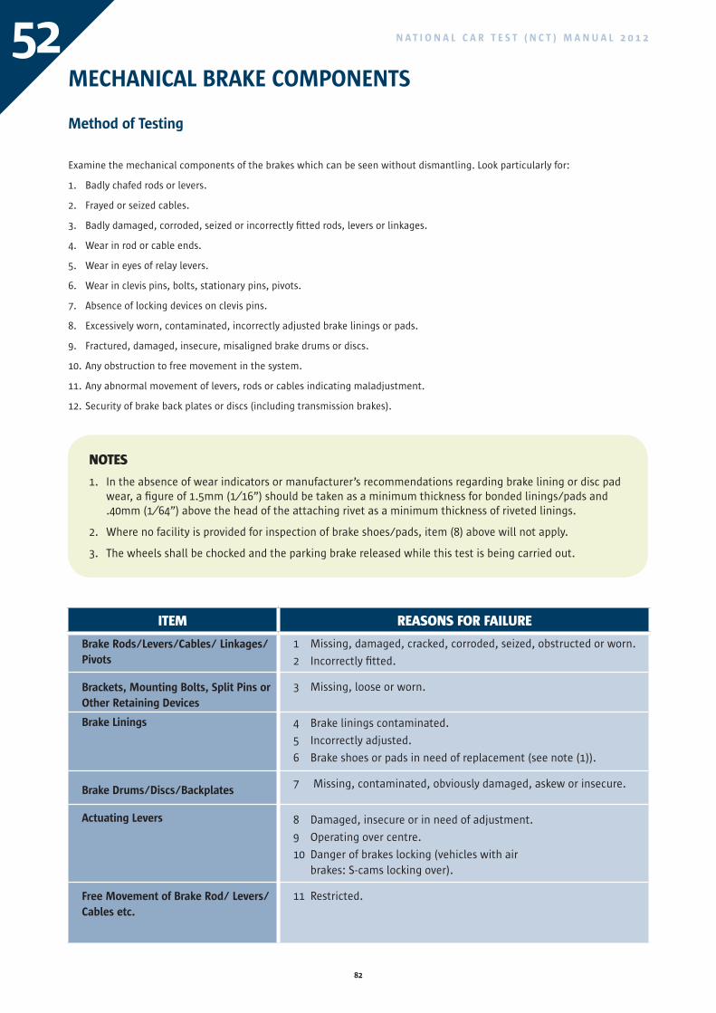
82
N A T I O N A L C A R T E S T ( N C T ) M A N U A L 2 0 1 252MECHANICAL BRAKE COMPONENTS
Method of Testing
Examine the mechanical components of the brakes which can be seen without dismantling. Look particularly for:
1. Badly chafed rods or levers.
2. Frayed or seized cables.
3. Badly damaged, corroded, seized or incorrectly fitted rods, levers or linkages.
4. Wear in rod or cable ends.
5. Wear in eyes of relay levers.
6. Wear in clevis pins, bolts, stationary pins, pivots.
7. Absence of locking devices on clevis pins.
8. Excessively worn, contaminated, incorrectly adjusted brake linings or pads.
9. Fractured, damaged, insecure, misaligned brake drums or discs.
10. Any obstruction to free movement in the system.
11. Any abnormal movement of levers, rods or cables indicating maladjustment.
12. Security of brake back plates or discs (including transmission brakes).
ITEM REASONS FOR FAILURE
Brake Rods/Levers/Cables/ Linkages/Pivots
Brackets, Mounting Bolts, Split Pins or Other Retaining Devices
Brake Linings
Brake Drums/Discs/Backplates
Actuating Levers
Free Movement of Brake Rod/ Levers/Cables etc.
1 Missing, damaged, cracked, corroded, seized, obstructed or worn.
2 Incorrectly fitted.
3 Missing, loose or worn.
4 Brake linings contaminated.
5 Incorrectly adjusted.
6 Brake shoes or pads in need of replacement (see note (1)).
7 Missing, contaminated, obviously damaged, askew or insecure.
8 Damaged, insecure or in need of adjustment.
9 Operating over centre.
10 Danger of brakes locking (vehicles with air brakes: S-cams locking over).
11 Restricted.
NOTES
1. In the absence of wear indicators or manufacturer’s recommendations regarding brake lining or disc pad wear, a figure of 1.5mm (1⁄16”) should be taken as a minimum thickness for bonded linings/pads and .40mm (1⁄64”) above the head of the attaching rivet as a minimum thickness of riveted linings.
2. Where no facility is provided for inspection of brake shoes/pads, item (8) above will not apply.
3. The wheels shall be chocked and the parking brake released while this test is being carried out.
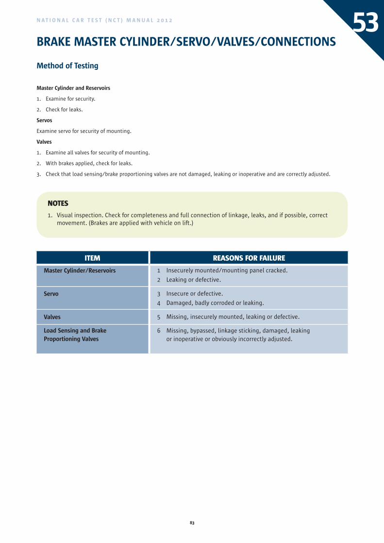
83
N A T I O N A L C A R T E S T ( N C T ) M A N U A L 2 0 1 2 53BRAKE MASTER CYLINDER/SERVO/VALVES/CONNECTIONS
Method of Testing
Master Cylinder and Reservoirs
1. Examine for security.
2. Check for leaks.
Servos
Examine servo for security of mounting.
Valves
1. Examine all valves for security of mounting.
2. With brakes applied, check for leaks.
3. Check that load sensing/brake proportioning valves are not damaged, leaking or inoperative and are correctly adjusted.
ITEM REASONS FOR FAILURE
Master Cylinder/Reservoirs
Servo
Valves
Load Sensing and Brake Proportioning Valves
1 Insecurely mounted/mounting panel cracked.
2 Leaking or defective.
3 Insecure or defective.
4 Damaged, badly corroded or leaking.
5 Missing, insecurely mounted, leaking or defective.
6 Missing, bypassed, linkage sticking, damaged, leaking or inoperative or obviously incorrectly adjusted.
NOTES
1. Visual inspection. Check for completeness and full connection of linkage, leaks, and if possible, correct movement. (Brakes are applied with vehicle on lift.)
ITEM REASONS FOR FAILURE
Brake Rods/Levers/Cables/ Linkages/Pivots
Brackets, Mounting Bolts, Split Pins or Other Retaining Devices
Brake Linings
Brake Drums/Discs/Backplates
Actuating Levers
Free Movement of Brake Rod/ Levers/Cables etc.
1 Missing, damaged, cracked, corroded, seized, obstructed or worn.
2 Incorrectly fitted.
3 Missing, loose or worn.
4 Brake linings contaminated.
5 Incorrectly adjusted.
6 Brake shoes or pads in need of replacement (see note (1)).
7 Missing, contaminated, obviously damaged, askew or insecure.
8 Damaged, insecure or in need of adjustment.
9 Operating over centre.
10 Danger of brakes locking (vehicles with air brakes: S-cams locking over).
11 Restricted.
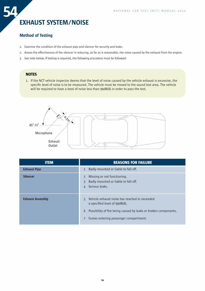
84
N A T I O N A L C A R T E S T ( N C T ) M A N U A L 2 0 1 254EXHAUST SYSTEM/NOISE
Method of Testing
1. Examine the condition of the exhaust pipe and silencer for security and leaks.
2. Assess the effectiveness of the silencer in reducing, as far as is reasonable, the noise caused by the exhaust from the engine.
3. See note below. If testing is required, the following procedure must be followed:
NOTES
1. If the NCT vehicle inspector deems that the level of noise caused by the vehicle exhaust is excessive, the specific level of noise is to be measured. The vehicle must be moved to the sound test area. The vehicle will be required to have a level of noise less than 99dB(A) in order to pass the test.
Microphone
45o ±1o
ExhaustOutlet
ITEM REASONS FOR FAILURE
Exhaust Pipe
Silencer
Exhaust Assembly
1 Badly mounted or liable to fall off.
2 Missing or not functioning.
3 Badly mounted or liable to fall off.
4 Serious leaks.
5 Vehicle exhaust noise has reached or exceeded a specified level of 99dB(A).
6 Possibility of fire being caused by leaks or broken components.
7 Fumes entering passenger compartment.
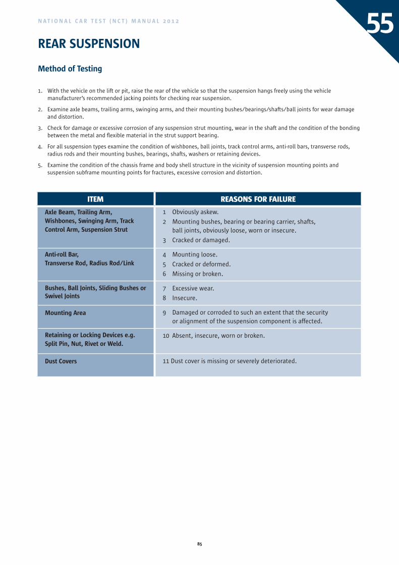
85
N A T I O N A L C A R T E S T ( N C T ) M A N U A L 2 0 1 2
REAR SUSPENSION
Method of Testing
1. With the vehicle on the lift or pit, raise the rear of the vehicle so that the suspension hangs freely using the vehicle manufacturer’s recommended jacking points for checking rear suspension.
2. Examine axle beams, trailing arms, swinging arms, and their mounting bushes/bearings/shafts/ball joints for wear damage and distortion.
3. Check for damage or excessive corrosion of any suspension strut mounting, wear in the shaft and the condition of the bonding between the metal and flexible material in the strut support bearing.
4. For all suspension types examine the condition of wishbones, ball joints, track control arms, anti-roll bars, transverse rods, radius rods and their mounting bushes, bearings, shafts, washers or retaining devices.
5. Examine the condition of the chassis frame and body shell structure in the vicinity of suspension mounting points and suspension subframe mounting points for fractures, excessive corrosion and distortion.
55
ITEM REASONS FOR FAILURE
Axle Beam, Trailing Arm,Wishbones, Swinging Arm, Track Control Arm, Suspension Strut
Anti-roll Bar,Transverse Rod, Radius Rod/Link
Bushes, Ball Joints, Sliding Bushes or Swivel Joints
Mounting Area
Retaining or Locking Devices e.g. Split Pin, Nut, Rivet or Weld.
Dust Covers
1 Obviously askew.
2 Mounting bushes, bearing or bearing carrier, shafts, ball joints, obviously loose, worn or insecure.
3 Cracked or damaged.
4 Mounting loose.
5 Cracked or deformed.
6 Missing or broken.
7 Excessive wear.
8 Insecure.
9 Damaged or corroded to such an extent that the security or alignment of the suspension component is affected.
10 Absent, insecure, worn or broken.
11 Dust cover is missing or severely deteriorated.
ITEM REASONS FOR FAILURE
Exhaust Pipe
Silencer
Exhaust Assembly
1 Badly mounted or liable to fall off.
2 Missing or not functioning.
3 Badly mounted or liable to fall off.
4 Serious leaks.
5 Vehicle exhaust noise has reached or exceeded a specified level of 99dB(A).
6 Possibility of fire being caused by leaks or broken components.
7 Fumes entering passenger compartment.
86
N A T I O N A L C A R T E S T ( N C T ) M A N U A L 2 0 1 256REAR SPRINGS
Method of Testing
Leaf Springs
1. Examine each spring for its general condition and in particular for fractures in the leaves, especially in the vicinity of the anchor eye of the main leaf.
2. Note whether any spring is so weak that it is not holding the body sufficiently far away from the wheels.
3. Examine condition of spring eyes and bushes.
4. Check that no spring clamps are missing.
5. Check that the springs on each axle are symmetrically located.
6. Check that there is no movement of spring leaves denoting a fractured centre bolt.
7. Check that the attachments of the shackle/anchor brackets to the chassis are secure, looking for signs of movement of rivets or bolts, and elongated holes.
8. Examine the bolts and/or nuts securing the spring to the axle for tightness, and examine the spring and axle for evidence that these have been moving relative to each other.
Coil Springs
9. Examine each spring for its general condition and in particular for fractures.
10. Note whether any spring is so weak that it is not holding the body sufficiently far away from the wheels.
11. Examine the attachment of the coil springs for security.
Torsion Bar
12. Check torsion bars/bushes for fracture or damage.
13. Examine the attachment of torsion bars.
Spring Pins and Bushes
14. Examine the amount of play due to wear at spring anchor brackets and pins of the spring shackles.
15. Examine the condition and security of any slipper brackets.
16. Check that anchor/shackle pins are fully in place, that they are secure and that locking devices are in position and secure.
17. Examine the spring mountings for excessive side play.
Air and Fluid Suspension
18. Check for leaks and the condition of the supply lines and suspension bellows.
19. Check the condition of levelling valve linkages.
20. Examine the attachment of the suspension bellows for security.
21. Examine the attachments for security to frame and axle.
Bonded Suspension Units
22. Examine the bonding of the flexible element to its associated metal fixings.
23. Examine the condition of the flexible element by applying pressure.
24. Examine the attachments for security to frame and axle.
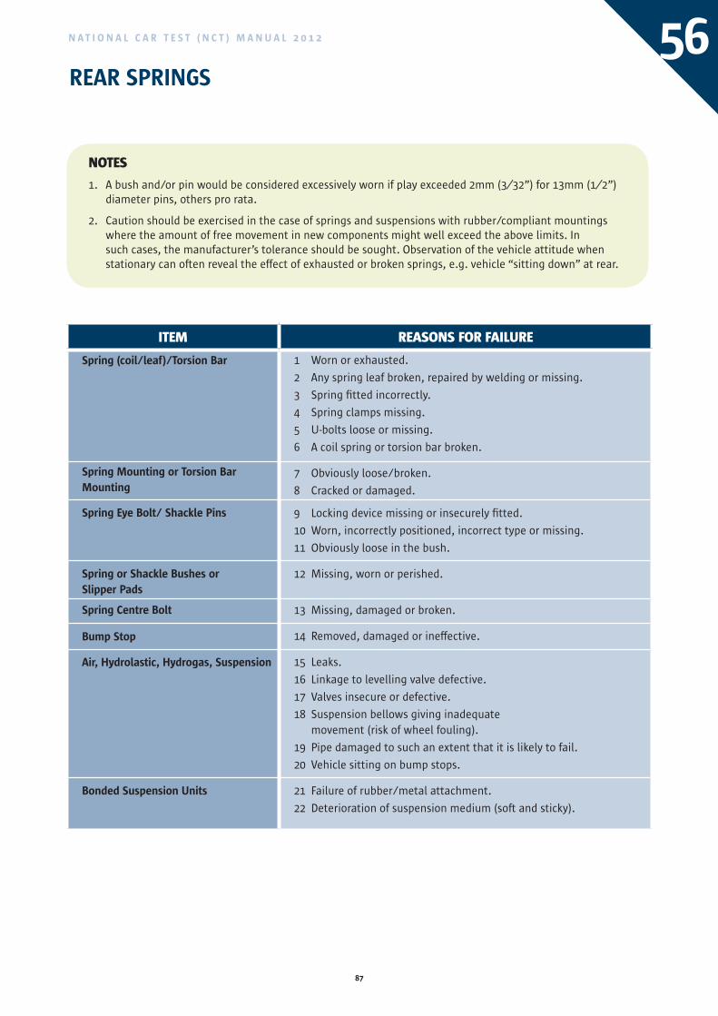
87
N A T I O N A L C A R T E S T ( N C T ) M A N U A L 2 0 1 2 56REAR SPRINGS
NOTES
1. A bush and/or pin would be considered excessively worn if play exceeded 2mm (3⁄32”) for 13mm (1⁄2”) diameter pins, others pro rata.
2. Caution should be exercised in the case of springs and suspensions with rubber/compliant mountings where the amount of free movement in new components might well exceed the above limits. In such cases, the manufacturer’s tolerance should be sought. Observation of the vehicle attitude when stationary can often reveal the effect of exhausted or broken springs, e.g. vehicle “sitting down” at rear.
ITEM REASONS FOR FAILURE
Spring (coil/leaf)/Torsion Bar
Spring Mounting or Torsion Bar Mounting
Spring Eye Bolt/ Shackle Pins
Spring or Shackle Bushes or Slipper Pads
Spring Centre Bolt
Bump Stop
Air, Hydrolastic, Hydrogas, Suspension
Bonded Suspension Units
1 Worn or exhausted.
2 Any spring leaf broken, repaired by welding or missing.
3 Spring fitted incorrectly.
4 Spring clamps missing.
5 U-bolts loose or missing.
6 A coil spring or torsion bar broken.
7 Obviously loose/broken.
8 Cracked or damaged.
9 Locking device missing or insecurely fitted.
10 Worn, incorrectly positioned, incorrect type or missing.
11 Obviously loose in the bush.
12 Missing, worn or perished.
13 Missing, damaged or broken.
14 Removed, damaged or ineffective.
15 Leaks.
16 Linkage to levelling valve defective.
17 Valves insecure or defective.
18 Suspension bellows giving inadequate movement (risk of wheel fouling).
19 Pipe damaged to such an extent that it is likely to fail.
20 Vehicle sitting on bump stops.
21 Failure of rubber/metal attachment.
22 Deterioration of suspension medium (soft and sticky).
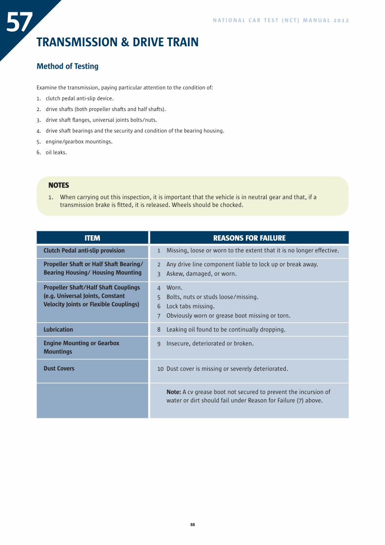
88
N A T I O N A L C A R T E S T ( N C T ) M A N U A L 2 0 1 257TRANSMISSION & DRIVE TRAIN
Method of Testing
Examine the transmission, paying particular attention to the condition of:
1. clutch pedal anti-slip device.
2. drive shafts (both propeller shafts and half shafts).
3. drive shaft flanges, universal joints bolts/nuts.
4. drive shaft bearings and the security and condition of the bearing housing.
5. engine/gearbox mountings.
6. oil leaks.
NOTES
1. When carrying out this inspection, it is important that the vehicle is in neutral gear and that, if a transmission brake is fitted, it is released. Wheels should be chocked.
ITEM REASONS FOR FAILURE
Clutch Pedal anti-slip provision
Propeller Shaft or Half Shaft Bearing/Bearing Housing/ Housing Mounting
Propeller Shaft/Half Shaft Couplings (e.g. Universal Joints, Constant Velocity Joints or Flexible Couplings)
Lubrication
Engine Mounting or Gearbox Mountings
Dust Covers
1 Missing, loose or worn to the extent that it is no longer effective.
2 Any drive line component liable to lock up or break away.
3 Askew, damaged, or worn.
4 Worn.
5 Bolts, nuts or studs loose/missing.
6 Lock tabs missing.
7 Obviously worn or grease boot missing or torn.
8 Leaking oil found to be continually dropping.
9 Insecure, deteriorated or broken.
10 Dust cover is missing or severely deteriorated.
Note: A cv grease boot not secured to prevent the incursion of water or dirt should fail under Reason for Failure (7) above.
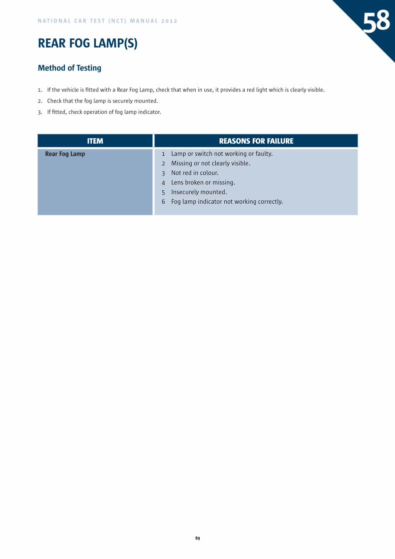
89
N A T I O N A L C A R T E S T ( N C T ) M A N U A L 2 0 1 2
REAR FOG LAMP(S)
Method of Testing
1. If the vehicle is fitted with a Rear Fog Lamp, check that when in use, it provides a red light which is clearly visible.
2. Check that the fog lamp is securely mounted.
3. If fitted, check operation of fog lamp indicator.
58
ITEM REASONS FOR FAILURE
Rear Fog Lamp 1 Lamp or switch not working or faulty.
2 Missing or not clearly visible.
3 Not red in colour.
4 Lens broken or missing.
5 Insecurely mounted.
6 Fog lamp indicator not working correctly.
ITEM REASONS FOR FAILURE
Clutch Pedal anti-slip provision
Propeller Shaft or Half Shaft Bearing/Bearing Housing/ Housing Mounting
Propeller Shaft/Half Shaft Couplings (e.g. Universal Joints, Constant Velocity Joints or Flexible Couplings)
Lubrication
Engine Mounting or Gearbox Mountings
Dust Covers
1 Missing, loose or worn to the extent that it is no longer effective.
2 Any drive line component liable to lock up or break away.
3 Askew, damaged, or worn.
4 Worn.
5 Bolts, nuts or studs loose/missing.
6 Lock tabs missing.
7 Obviously worn or grease boot missing or torn.
8 Leaking oil found to be continually dropping.
9 Insecure, deteriorated or broken.
10 Dust cover is missing or severely deteriorated.
Note: A cv grease boot not secured to prevent the incursion of water or dirt should fail under Reason for Failure (7) above.
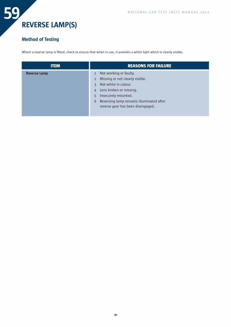
90
N A T I O N A L C A R T E S T ( N C T ) M A N U A L 2 0 1 259REVERSE LAMP(S)
Method of Testing
Where a reverse lamp is fitted, check to ensure that when in use, it provides a white light which is clearly visible.
ITEM REASONS FOR FAILURE
Reverse Lamp 1 Not working or faulty.
2 Missing or not clearly visible.
3 Not white in colour.
4 Lens broken or missing.
5 Insecurely mounted.
6 Reversing lamp remains illuminated after reverse gear has been disengaged.
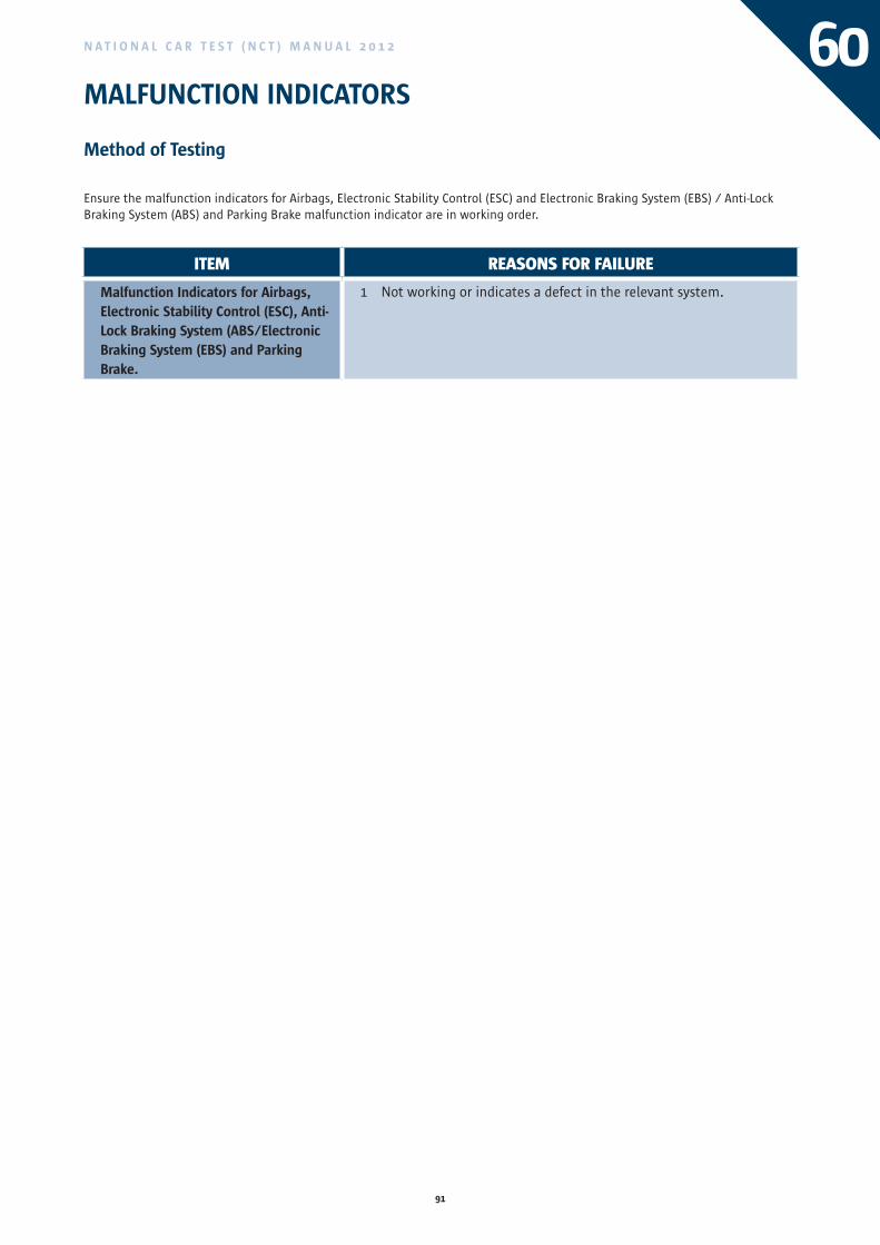
91
N A T I O N A L C A R T E S T ( N C T ) M A N U A L 2 0 1 2 60MALFUNCTION INDICATORS
Method of Testing
Ensure the malfunction indicators for Airbags, Electronic Stability Control (ESC) and Electronic Braking System (EBS) / Anti-Lock Braking System (ABS) and Parking Brake malfunction indicator are in working order.
ITEM REASONS FOR FAILURE
Malfunction Indicators for Airbags, Electronic Stability Control (ESC), Anti-Lock Braking System (ABS/Electronic Braking System (EBS) and Parking Brake.
1 Not working or indicates a defect in the relevant system.
ITEM REASONS FOR FAILURE
Reverse Lamp 1 Not working or faulty.
2 Missing or not clearly visible.
3 Not white in colour.
4 Lens broken or missing.
5 Insecurely mounted.
6 Reversing lamp remains illuminated after reverse gear has been disengaged.
92
N A T I O N A L C A R T E S T ( N C T ) M A N U A L 2 0 1 261REGISTRATION PLATE LAMPS
Method of Testing
Check that the registration number plate lamp(s) shows a white light and is operating effectively.
ITEM REASONS FOR FAIL ADvISORY
Registration Plate Lamp 1 Not working, faulty or not fitted.
2 Not white in colour.
3 Lens missing or broken.
4 Showing direct (not reflected) white light to the rear.

93
N A T I O N A L C A R T E S T ( N C T ) M A N U A L 2 0 1 2

94
N A T I O N A L C A R T E S T ( N C T ) M A N U A L 2 0 1 2

Údarás Um Shábháilteacht Ar BhóithreRoad Safety Authority
NATIONAL CAR TEST (NCT) MANUAL 2012Passenger Vehicles (Up to 8 Passengers)
Údarás Um Shábháilteacht Ar Bhóithre
Road Safety Authority
Páirc Ghnó Ghleann na Muaidhe, Cnoc an tSabhaircín, Bóthar Bhaile Átha Cliath, Béal an Átha, Co. Mhaigh Eo
Moy Valley Business Park, Primrose Hill, Dublin Road, Ballina, Co. Mayo
locall: 1890 50 60 80 fax: (096) 25252 email: [email protected] website: www.rsa.ie
Revision 2
BAILE ÁTHA CLIATH
ARNA FHOILSIÚ AG OIFIG AN tSOLÁTHAIR
Le ceannach díreach ón
OIFIG DHÍOLTA FOILSEACHÁN RIALTAIS
TEACH SUN ALLIANCE, SRÁID THEACH LAIGHEAN, BAILE ÁTHA CLIATH 2
nó tríd an bpost ó
FOILSEACHÁIN RIALTAIS, AN RANNÓG POST-TRÁCHTA
AONAD 20 PÁIRC MIONDÍOLA COIS LOCHA,CLÁR CHLAINNE MHUIRIS, CONTAE MHAIGH EO
(Teil: 01 – 6476834 nó 1890 213434; Fax 01 – 6476843 nó 094 - 9378964 )
nó trí aon díoltóir leabhar.
DUBLIN
PUBLISHED BY THE STATIONERY OFFICE
To be purchased directly from the
GOVERNMENT PUBLICATIONS SALE OFFICE
SUN ALLIANCE HOUSE, MOLESWORTH STREET, DUBLIN 2
or by mail order from
GOVERNMENT PUBLICATIONS, POSTAL TRADE SECTION
UNIT 20 LAKESIDE RETAIL PARK, CLAREMORRIS, CO. MAYO
(Tel: 01 – 6476834 or 1890 213434; Fax: 01 – 6476843 or 094 - 9378964)
or through any bookseller.
Working To Save Lives
NA
TIO
NA
L CA
R T
ES
T (N
CT
) MA
NU
AL 2
01
0 P
asse
ng
er V
eh
icles (U
p to
8 P
asse
ng
ers)