
Multi-Stage Design of DMS Filters with Free & Freeze Method
6
Multi-Stage Design of DMS Filters with Free & Freeze Method KIYOHARU TAGAWA Faculty of Engineering Kobe University Rokkodai Nada Kobe 657-8501 JAPAN HOEWON KIM Graduate School of Science and Technology Kobe University Rokkodai Nada Kobe 657-8501 JAPAN Abstract: The structural design of Double Mode Surface acoustic wave (DMS) filters, which are used widely for modern cellular phones, can be formulated as a combinatorial optimization problem. Even though the local search is usually efficient to solve the combinatorial optimization problem, the running time spent by the local search increases drastically when it is applied to a large-scale problem instance. Therefore, in order to solve the large-scale design problem of complex DMS filter in a short period, a new optimization technique named Free & Freeze method is proposed. Since Free & Freeze method is a kind of the divide-and-conquer method, it divides the search space of an optimization problem into two segments repeatedly, namely free-segment and freeze-segment, considering the problem landscape, and applies an efficient local search to the free-segment intensively. Key–Words: Surface acoustic wave filter, Optimum design and Local search 1 Introduction Surface Acoustic Wave (SAW) filters have played im- portant roles as key devices for various mobile and wireless communication systems, such as Personal Digital Assistants (PDAs) and cellular phones[1]. Es- pecially, Double Mode Surface acoustic wave (DMS) filters are used widely in their modern RF circuits, because they can provide small, rugged and cost- competitive mechanical bandpass filters with out- standing frequency response characteristics[2, 3]. The frequency response characteristics of SAW filters including DMS filters are governed primarily by their geometrical structures, namely, the config- urations of interdigital transducers (IDTs) and grat- ing reflectors fabricated on piezoelectric substrates. Therefore, in order to realize desirable frequency re- sponse characteristics of SAW filters, we have to de- cide their suitable structures. Because the structural design problems of SAW filters can’t be solved the- oretically, they are formulated as optimization prob- lems. Then optimum design techniques coupling opti- mization methods with computer simulations are used to solve the optimization problems[4, 5, 6, 7, 8]. In recent years, cellular phones have become highly efficient with many functions. Since DMS fil- ters are key devices for such modern cellular phones, the demand for high performance DMS filters meeting various specifications, such as high stop-band attenu- ation, low insertion loss, impedance transformation, balun functionality and so on, has increased. In order to satisfy these severe specifications, the structures of DMS filters have become extremely complex. Con- sequently, the numbers of design parameters used to describe DMS filters’ structures, or the decision vari- ables of optimization problems, have increased dras- tically. Besides, computational time spent to evaluate the performance of such a DMS filter based on com- puter simulation has also increased[9]. In this paper, to cope well with the large-scale design problems of DMS filters, a new optimization technique named Free & Freeze method is proposed. Since Free & Freeze method is a kind of the divide- and-conquer method, it divides the search space of an optimization problem into two segments repeatedly, namely free-segment and freeze-segment, and applies a local search to the free-segment intensively. As an efficient local search used in Free & Freeze method, Variable Neighborhood Search (VNS)[6] offered by authors is employed. That is because VNS has been applied successfully to various types of optimum de- sign problems of SAW filters[6, 7, 8]. 2 Double Mode SAW Filter 2.1 Structure of DMS Filter Figure 1 shows a typical structure of double mode SAW (DMS) filter, which consists of five components: one receiver IDT (IDT-1), two transmitter IDTs (IDT- 2) and two grating reflectors realized by shorted metal strip arrays (SMSA). Each of IDTs is composed of Proceedings of the 6th WSEAS International Conference on Applied Computer Science, Tenerife, Canary Islands, Spain, December 16-18, 2006 508
Transcript of Multi-Stage Design of DMS Filters with Free & Freeze Method

Multi-Stage Design of DMS Filters with Free & Freeze Method
KIYOHARU TAGAWAFaculty of Engineering
Kobe UniversityRokkodai Nada Kobe 657-8501
JAPAN
HOEWON KIMGraduate School of Science and Technology
Kobe UniversityRokkodai Nada Kobe 657-8501
JAPAN
Abstract: The structural design of Double Mode Surface acoustic wave (DMS) filters, which are used widelyfor modern cellular phones, can be formulated as a combinatorial optimization problem. Even though the localsearch is usually efficient to solve the combinatorial optimization problem, the running time spent by the localsearch increases drastically when it is applied to a large-scale problem instance. Therefore, in order to solve thelarge-scale design problem of complex DMS filter in a short period, a new optimization technique named Free &Freeze method is proposed. Since Free & Freeze method is a kind of the divide-and-conquer method, it divides thesearch space of an optimization problem into two segments repeatedly, namely free-segment and freeze-segment,considering the problem landscape, and applies an efficient local search to the free-segment intensively.
Key–Words: Surface acoustic wave filter, Optimum design and Local search
1 Introduction
Surface Acoustic Wave (SAW) filters have played im-portant roles as key devices for various mobile andwireless communication systems, such as PersonalDigital Assistants (PDAs) and cellular phones[1]. Es-pecially, Double Mode Surface acoustic wave (DMS)filters are used widely in their modern RF circuits,because they can provide small, rugged and cost-competitive mechanical bandpass filters with out-standing frequency response characteristics[2, 3].
The frequency response characteristics of SAWfilters including DMS filters are governed primarilyby their geometrical structures, namely, the config-urations of interdigital transducers (IDTs) and grat-ing reflectors fabricated on piezoelectric substrates.Therefore, in order to realize desirable frequency re-sponse characteristics of SAW filters, we have to de-cide their suitable structures. Because the structuraldesign problems of SAW filters can’t be solved the-oretically, they are formulated as optimization prob-lems. Then optimum design techniques coupling opti-mization methods with computer simulations are usedto solve the optimization problems[4, 5, 6, 7, 8].
In recent years, cellular phones have becomehighly efficient with many functions. Since DMS fil-ters are key devices for such modern cellular phones,the demand for high performance DMS filters meetingvarious specifications, such as high stop-band attenu-ation, low insertion loss, impedance transformation,balun functionality and so on, has increased. In order
to satisfy these severe specifications, the structures ofDMS filters have become extremely complex. Con-sequently, the numbers of design parameters used todescribe DMS filters’ structures, or the decision vari-ables of optimization problems, have increased dras-tically. Besides, computational time spent to evaluatethe performance of such a DMS filter based on com-puter simulation has also increased[9].
In this paper, to cope well with the large-scaledesign problems of DMS filters, a new optimizationtechnique named Free & Freeze method is proposed.Since Free & Freeze method is a kind of the divide-and-conquer method, it divides the search space of anoptimization problem into two segments repeatedly,namely free-segment and freeze-segment, and appliesa local search to the free-segment intensively. As anefficient local search used in Free & Freeze method,Variable Neighborhood Search (VNS)[6] offered byauthors is employed. That is because VNS has beenapplied successfully to various types of optimum de-sign problems of SAW filters[6, 7, 8].
2 Double Mode SAW Filter
2.1 Structure of DMS Filter
Figure 1 shows a typical structure of double modeSAW (DMS) filter, which consists of five components:one receiver IDT (IDT-1), two transmitter IDTs (IDT-2) and two grating reflectors realized by shorted metalstrip arrays (SMSA). Each of IDTs is composed of
Proceedings of the 6th WSEAS International Conference on Applied Computer Science, Tenerife, Canary Islands, Spain, December 16-18, 2006 508
IDT-1
SMSA
IDT-2
SMSA
IDT-2
input
output
Figure 1: Double mode SAW filter
SMSAIDT-2IDT-1
w
lplm
Drprm
N1 N2 Nr
H
substrate
rm
W : overlap between electrodesN1 : number of fingers of receiver IDT-1N2 : ditto of transmitter IDT-2Nr : number of strips of SMSAD : gap between IDT-1 and IDT-2ξ : metallization ratio of IDT
ξr : ditto of SMSAρr : pitch ratio of SMSA to IDTH : thickness of electrode
Figure 2: Design parameters of DMS filter
some pairs of electrodes called fingers and used forSAW excitation and detection. Since the DMS fil-ter is designed to resonate at two different frequency-modes, it has a symmetric structure[2, 3].
The frequency response characteristics of DMSfilters depend on their structures, or the configurationsof components fabricated on piezoelectric substrates.For example, in order to decide a suitable structure ofthe DMS filter in Fig. 1, we need to adjust nine designparameters listed in Fig. 2. Since the DMS filter hasa symmetric structure, Fig. 2 illustrates only its righthalf side. The metallization ratio of IDT is defined bythe ratio of the finger’s width lm to the pitch of IDT’sfinger lp as ξ = lm/lp. Similarly, the metallizationratio of SMSA is defined as ξr = rm/rp. The pitchratio of SMSA to IDT is given by ρr = rp/lp.
From now on, the nine design parameters listedin Fig. 2 are referred as decision variables and rep-resented by using a vector of n = 9 elements: x =(x1, · · · , xn). By the way, some design parameters,such as the numbers of IDTs’ fingers, take the valuesof positive integers. Besides, the lithographic reso-lution for shaping IDTs’ electrodes is also restricted
port-1
port-3
port-2Z1
1: A10 1: A20
CT
Z2
mY
Z1
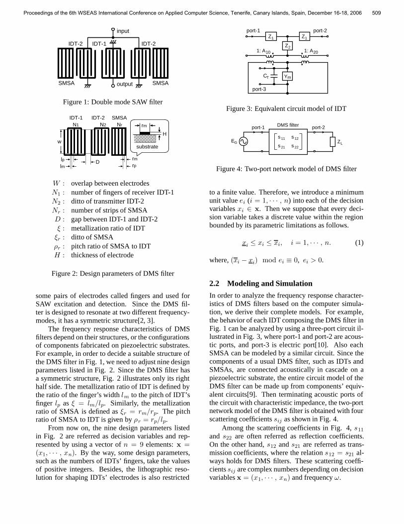
Figure 3: Equivalent circuit model of IDT
DMS filter
EG
port-1
s 11
s 22
s 12
s 21
port-2
ZL
Figure 4: Two-port network model of DMS filter
to a finite value. Therefore, we introduce a minimumunit value ei (i = 1, · · · , n) into each of the decisionvariables xi ∈ x. Then we suppose that every deci-sion variable takes a discrete value within the regionbounded by its parametric limitations as follows.
xi ≤ xi ≤ xi, i = 1, · · · , n. (1)
where, (xi − xi) mod ei ≡ 0, ei > 0.
2.2 Modeling and Simulation
In order to analyze the frequency response character-istics of DMS filters based on the computer simula-tion, we derive their complete models. For example,the behavior of each IDT composing the DMS filter inFig. 1 can be analyzed by using a three-port circuit il-lustrated in Fig. 3, where port-1 and port-2 are acous-tic ports, and port-3 is electric port[10]. Also eachSMSA can be modeled by a similar circuit. Since thecomponents of a usual DMS filter, such as IDTs andSMSAs, are connected acoustically in cascade on apiezoelectric substrate, the entire circuit model of theDMS filter can be made up from components’ equiv-alent circuits[9]. Then terminating acoustic ports ofthe circuit with characteristic impedance, the two-portnetwork model of the DMS filter is obtained with fourscattering coefficients sij as shown in Fig. 4.
Among the scattering coefficients in Fig. 4, s11
and s22 are often referred as reflection coefficients.On the other hand, s12 and s21 are referred as trans-mission coefficients, where the relation s12 = s21 al-ways holds for DMS filters. These scattering coeffi-cients sij are complex numbers depending on decisionvariables x = (x1, · · · , xn) and frequency ω.
Proceedings of the 6th WSEAS International Conference on Applied Computer Science, Tenerife, Canary Islands, Spain, December 16-18, 2006 509

3 Problem Formulation
3.1 Criteria of Frequency ResponseIn order to evaluate the performance of DMS filters,we use three criteria of their frequency response char-acteristics. First of all, from the above reflection coef-ficients sii (i = 1, 2) in Fig. 4, standing wave ratiosΓ1 and Γ2 are defined for the input- and output-portsof the network model of DMS filter as follows.⎡
⎢⎢⎣Γ1(x, ω) =
1 + |s11(x, ω)|1− |s11(x, ω)|
Γ2(x, ω) =1 + |s22(x, ω)|1− |s22(x, ω)|
(2)
Besides them, from the transmission coefficients21, the attenuation Γ3 is also defined as follows.
Γ3(x, ω) = − 20 log(|s21(x, ω)|) (3)
Now, the performance of DMS filters is specifiedby using the upper and lower bounds of the abovethree criteria Γh (h = 1, 2, 3). Let Ω be a setof frequencies ω ∈ Ω sampled from the remarkablefrequency range of a target DMS filter including itspassing- and stop-bands. Γh(x, ω) denotes the valueof the criterion Γh evaluated at ω ∈ Ω with a givenvector of decision variables x = (x1, · · · , xn). Byusing the upper Uh(ω) and the lower Lh(ω) bounds,Γh(x, ω) is restricted at each ω ∈ Ω as follows.
Lh(ω) ≤ Γh(x, ω) ≤ Uh(ω), h = 1, 2, 3. (4)
Consequently, in the structural design of DMS fil-ters, we have only to minimize the following objectivefunction derived from the constraints in (4).
f(x) =∑ω∈Ω
∇U (x, ω) + ∇L(x, ω)|Ω| (5)
⎡⎢⎢⎢⎢⎢⎣
∇U(x, ω) =3∑
h=1
max{Γh(x, ω) − Uh(ω), 0 }
∇L(x, ω) =3∑
h=1
max{Lh(ω) − Γh(x, ω), 0 }
3.2 Optimum Design of DMS FilterThe structural design of a DMS filter is formulated asan optimization problem. Let X be the search spaceof solutions, namely the whole set of possible decisionvariables xi ∈ x constrained by (1). For minimizingthe objective function f(x) in (5), the optimizationproblem can be described mathematically as follows.[
minimize f(x)
subject to x ∈ X(6)
4 Free & Freeze Method
4.1 NeighborhoodThe neighborhood N(x) is generally a set of solutionsthat resemble the solution x ∈ X [11]. We adopt thek-degree-neighborhood Nk(x) (k ≤ n) that is definedas follows[6]: every solution x ′ ∈ Nk(x) differs fromthe solution x in just k elements, and the differencebetween elements x′
i ∈ x′ and xi ∈ x is equiva-lent to their minimum unit value as e i = |x′
i − xi|.For solving the optimization problem in (6), VariableNeighborhood Search (VNS) explores several neigh-borhoods Nk(x) (k = 1, · · · , k), and jumps fromthere to a new one if and only if an improvement wasmade. Therefore, the locally optimal solution x� ∈ Xfound by VNS is defined exactly as follows.
f(x�) ≤ f(x), ∀x ∈k⋃
k=1
Nk(x�) ∩ X . (7)
Since VNS guarantees only to find a locally op-timal solution defined by (7), the quality of the fi-nal solution seems to be improved by searching a lotof neighborhoods. However, the computational timespent by VNS increases with the number of them. Ex-actly, the total number of solutions included in neigh-borhoods Nk(x) (k = 1, · · · , k) rises drasticallywith the maximum degree of neighborhood k and thenumber of decision variables n as follows.
|k⋃
k=1
Nk(x)| =k∑
k=1
|Nk(x)| =k∑
k=1
2knCk (8)
4.2 Move StrategySince VNS investigates more than one neighborhood,it is important to settle the order of them in the search.A unique search strategy named the introvert searchis used in the VNS proposed by authors[6]. Conven-tional VNSs look for an improvement moving fromthe smallest neighborhood to the largest one[12]. Onthe other hand, the proposed introvert VNS (I-VNS)takes a contrary motion in the search. As a result, I-VNS can hardly fall into poor optima, because it copeswell with the problem of epistasis[13], i.e., the syner-gistic relation between different variables.
4.3 Selection RuleAs we have mentioned previously, Free & Freezemethod is a kind of the divide-and-conquer method.So, it divides the search space of an optimizationproblem into two segments, namely free-segment andfreeze-segment, and applies the above I-VNS to the
Proceedings of the 6th WSEAS International Conference on Applied Computer Science, Tenerife, Canary Islands, Spain, December 16-18, 2006 510

free-segment. First of all, an incumbent x of I-VNSis regarded as a set of decision variables x i ∈ xand divided into two subsets such as x = x F ∪ xZ .From now on, xi ∈ xF are called “free-variables” andxj ∈ xZ are called “freeze-variables”. The valuesof the freeze-variables are fixed until the procedure ofexclusive I-VNS ends. On the other hand, the valuesof the free-variables are changed by I-VNS for im-proving the objective function’s value f(x).
In order to choose the free-variables xi ∈ xF
from a solution x in Free & Freeze method, we canuse the designer’s knowledge about the design prob-lems of DMS filters. Furthermore, for choosing thefree-variables xi ∈ xF ⊆ x automatically, we pro-pose three selection-rules, namely “random”, “sensi-tivity analysis” and “epistasis analysis”. In the ran-dom selection-rule, the free-variables xi ∈ xF arechosen randomly. On the other hand, in the sensitivityanalysis and the epistasis analysis selection-rules, ev-ery decision variable xi ∈ x (i = 1, · · · , n) includedin a solution x is given its priority p(x i) detailed later.Then some free-variables xi ∈ xF are chosen fromxi ∈ x according to their priorities.
In order to decide the priority p(x i) for a decisionvariable xi ∈ x, the sensitivity analysis selection-ruleevaluates the effect of the small change of the deci-sion variable xi ∈ x on the objective function’s value.Therefore, the priority p(xi) is defined as follows.
p(xi) = | ∇f(xi) |, i = 1, · · · , n. (9)
[∇f(xi) = f(x1, · · · , xi + ei, · · · , xn)
−f(x1, · · · , xn)
In addition to the sole effect of x i evaluated in(9), epistasis analysis selection-rule considers the syn-ergetic effect caused by the simultaneous changes oftwo different variables xi ∈ x and xj ∈ x (j = i).Therefore, the priority p(xi) is defined as follows.
p(xi) = max{ p̂(xi), | ∇f(xi) | } (10)
⎡⎢⎢⎢⎢⎣
p̂(xi) = maxj
{ |∇f(xi, xj)− ∇f(xj) | }∇f (xi, xj) = f(x1, · · · , xi + ei, · · ·
· · · , xj + ej, · · · , xn)−f(x1, · · · , xn), j = i.
In Free & Freeze method, the period of execut-ing I-VNS one time is called “stage”. Besides thetotal number of stages m, the maximum degree ofneighborhood km and the number of free-variablesnm (1 ≤ nm ≤ n) need to be specified for each stage
input
output output
Figure 5: Tandem type DMS filter
m (m = 1, · · · , m). Therefore, the strategy of Free& Freeze method means a set of the above (m×2+1)parameters coupled with the selection-rules of free-variables, namely, random, sensitivity analysis, epis-tasis analysis and the knowledge of designer.
In the following procedure of Free & Freezemethod, the k-degree-neighborhood Nk(xF ) is de-fined as well as the conventional Nk(x). Also a subsetDk(xF ) ⊆ Nk(xF ) is defined as shown in (11).
Dk(xF ) = {x′F ∈ Nk(xF ) ∩ X |f(x′F ∪ xZ) < f(xF ∪ xZ) } (11)
[Free & Freeze method]
Step 1: Get an initial solution x ∈ X . Let m := 1.
Step 2: Select nm variables xi ∈ x for xF ⊆ x.
Step 3: Let k := km.
Step 4: If Dk(xF ) = ∅, choose x′F ∈ Dk(xF ), letxF := x′F and go back to Step 3.
Step 5: If k = 1 holds, let x := xF ∪xZ . Otherwise,let k := k − 1 and go back to Step 4.
Step 6: If m = m holds, return x and end. Other-wise, let m := m + 1 and go back to Step 2.
5 Experimental Results
5.1 Problem InstancesFree & Freeze method was applied to the structuraldesign of a tandem type DMS filter shown in Fig. 5.The tandem type DMS filter consists of two DMS fil-ters connected before and after. Furthermore, each ofthe DMS filters consists of nine components, namelyseven IDTs and two SMSAs. Therefore, in order to
Proceedings of the 6th WSEAS International Conference on Applied Computer Science, Tenerife, Canary Islands, Spain, December 16-18, 2006 511

Table 1: Search space of tandem DMS filteri xi, xi ei i xi, xi ei
1 250, 350 10 13 250, 350 102 10.0, 20.0 0.5 14 10.0, 20.0 0.53 15.5, 25.5 1.0 15 15.5, 25.5 1.04 1.0, 3.0 1.0 16 1.0, 3.0 1.05 150, 250 10 17 150, 250 106 0.0, 0.8 0.1 18 0.0, 0.8 0.17 3.0, 7.0 0.5 19 3.0, 7.0 0.58 3.0, 7.0 0.5 20 3.0, 7.0 0.59 9.1, 10.0 0.1 21 9.1, 10.0 0.110 10.0, 10.6 0.1 22 10.0, 10.6 0.111 395, 399 1 23 395, 399 112 19.8, 20.2 0.2 24 19.8, 20.2 0.2
Table 2: Strategy in experiment 1m 1 2 3 4nm 24 12 12 12km 1 3 3 3
Table 3: Strategy in experiment 2m 1 2 3 4nm 12 6 6 6km 1 3 3 3
decide a suitable structure of the tandem type DMSfilter in Fig. 5, we have to consider n = 24 decisionvariables xi ∈ x (i = 1, · · · , n), which are similar tothe design parameters illustrated in Fig. 2.
Table 1 shows the search space X of the optimiza-tion problem, namely the upper and lower bounds ofn = 24 decision variables xi ∈ x and their minimumunit values ei (i = 1, · · · , n). In order to define theobjective function f(x) in (5), the upper and lowerbounds of three criteria Γh(x, ω) (h = 1, 2, 3) werespecified at 120 frequency points ω ∈ Ω.
5.2 Experiment 1In order to decide the suitable structure of the tan-dem type DMS filter shown in Fig. 5, Free & Freezemethod was applied to the above optimization prob-lem. The strategy described in Table 2 was employedfor Free & Freeze method. Furthermore, either one ofthree automatic selection-rules, namely random, sen-sitivity analysis and epistasis analysis, was used tochoose nm (nm ≤ n) free-variables xi ∈ xF .
Table 4 shows the experimental results in whichthree automatic selection-rules were compared inthe objective function’s values of the final solutions(fmin) and the total numbers of examined solutions(no. of x). From Table 4, Free & Freeze method com-bined with sensitivity analysis investigated so many
Table 4: Results of experiment 1selection fmin no. of xrandom 10.77 7525
sensitivity 5.13 10879epistasis 9.86 4714
Table 5: Results of experiment 2selection fmin no. of xrandom 12.58 1558
sensitivity 9.85 1040epistasis 10.74 2594
solutions that it could find the best solution. There-fore, it can be say that sensitivity analysis made thebest selection of free-variables xi ∈ xF . On the otherhand, random selection-rule did not work so well inspite of the number of examined solutions.
5.3 Experiment 2By using the designer’s knowledge about the struc-ture of the tandem type DMS filter in Fig. 5, two-step design approach was employed. In the first de-sign step, decision variables x i ∈ x (i = 13, · · · , 24)were chosen for free-variables xi ∈ xF ⊆ x, whilexj ∈ x (j = 1, · · · , 12) were chosen for freeze-variables xj ∈ xZ ⊆ x. Then the structure ofthe output-side single DMS filter was optimized ex-clusively. On the other hand, in the second designstep, xj ∈ x (j = 1, · · · , 12) were chosen for free-variables, while xi ∈ x (i = 12, · · · , 24) were cho-sen for freeze-variables. Then the structure of theinput-side DMS filter was optimized exclusively. Inboth of the two optimization problems, the strategy inTable 3 was employed for Free & Freeze method.
Table 5 shows the experimental results of thetwo-step design approach in the same way with Ta-ble 4. From the results in Table 5, Free & Freezemethod combined with sensitivity analysis selection-rule found the best solution again. Furthermore, fromTable 4 and Table 5, it can be say that the manual se-lection of free-variables xi ∈ xF based on the de-signer’s knowledge is efficient to reduce the compu-tational time spent by Free & Freeze method withoutlosing the quality of final solutions so much.
Figure 6 shows the attenuation Γ3(x�, ω) aboutthe final solution x� obtained by Free & Freezemethod combined with sensitivity analysis in Table 5.In Fig. 6, the attenuation of the initial solution is alsoplotted by one-broken line. Furthermore, the upperU3(ω) and the lower L3(ω) bounds of the criterion Γ3
are plotted by two-broken line. From the frequencyresponse characteristics shown in Fig. 6, we can con-
Proceedings of the 6th WSEAS International Conference on Applied Computer Science, Tenerife, Canary Islands, Spain, December 16-18, 2006 512

100
80
60
40
20
0
800 850 900 950 1000 1050 1100 1150 1200frequency [MHz]
atte
nuat
ion
[dB
]
Figure 6: Frequency responses (attenuation)
firm that the final solution obtained by using the pro-posed technique almost meets the specifications.
6 ConclusionIn this paper, for solving the large-scale design prob-lems of complex DMS filters in short periods, a newoptimization technique named Free & Freeze methodwas proposed. In the proposed method, the searchspace of an optimization problem was divided re-peatedly into two segments, namely free-segment andfreeze-segment. Then an efficient local search namedI-VNS was applied to the free-segment. Furthermore,for choosing several free-variables from decision vari-ables, three automatic selection-rules, namely ran-dom, sensitivity analysis and epistasis analysis, werepresented. From the experimental results conductedon a tandem type DMS filter, it developed that thesensitivity analysis selection-rule was superior to theother rules in the quality of final solution.
Future work will focus on the planning of the dex-terous strategies for Free & Freeze method. BecauseFree & Freeze method is applicable to the optimumdesign problems of various SAW devices, appropriatestrategies based on the designer’s knowledge about re-spective SAW devices become more important.
Acknowledgements: The research was supported inpart by Takahashi Industrial and Economic ResearchFoundation (Project No. 35-002B06).
References:
[1] C. K. Campbell, Surface Acoustic Wave Devicesfor Mobile and Wireless Communications, Aca-demic Press 1998
[2] H. Meier, T. Baier and G. Riha, Miniaturizationand advanced functionalities of SAW devices,IEEE Trans. on Microwave Theory and Tech-niques, vol. 49, no. 4, 2001, pp. 743–748.
[3] M. Kadota, T. Yoneda, K. Fujimoto, T. Nakaoand E. Takata, Resonator filters using shearhorizontal-type leaky surface acoustic wave con-sisting of heavy-metal electrode and quartzsubstrate, IEEE Trans. on Ultrasonics, Ferro-electrics, and Frequency Control, vol. 51, no. 2,2004, pp. 202–210.
[4] E. V. Bausk, Optimization of broadband with-drawal weighted interdigital transducers for highselective SAW filters, IEEE Trans. on Ultra-sonics, Ferroelectrics, and Frequency Control,vol. 46, no. 5, 1999, pp. 1276–1282.
[5] V. Prabhu, B. S. Panwar and Priyanka, Link-age learning genetic algorithm for the design ofwithdrawal weighted SAW filters, Proc. of IEEEUltrasonics Symposium, 2002, pp. 357–360.
[6] K. Tagawa, T. Tokunaga, H. Haneda, T. Igakiand S. Seki, Optimal design of three-IDT typeSAW filter using local search, Proc. of the 28thAnnual Conference of the IEEE Industrial Elec-tronics Society, 2002
[7] K. Tagawa, T. Ohtani, T. Igaki and S. Seki, Ro-bust optimum design of SAW filters by usingpenalty function method, Proc. of IEEE Inter-national Conference on Industrial Technology,2004
[8] K. Tagawa and M. Matsuoka, Optimum designof surface acoustic wave filters based on theTaguchi’s quality engineering with a memetic al-gorithm, Proc .of PPSN IX, LNCS 4193, 2006,pp. 292–301.
[9] K. Hashimoto, Surface Acoustic Wave Devicesin Telecommunications: Modeling and Simula-tion, Springer-Verlag, Berlin Heidelberg NewYork 2000
[10] T. Kojima and T. Suzuki, Fundamental equa-tions of electro-acoustic conversion for an inter-digital surface-acoustic-wave transducer by us-ing force factors, Japanese Journal of AppliedPhysics Supplement, vol. 31, 1992, pp. 194–197.
[11] E. Aarts and J. K. Lenstra (Eds.), Local Searchin Combinatorial Optimization, John Wiley &Sons, 1997
[12] N. Mladenovic and P. Hansen, Variable neigh-borhood search, Computers and Operations Re-search, vol. 24, no. 11, 1997, pp. 1097–1100.
[13] D. E. Goldberg, Genetic Algorithms in Search,Optimization, and Machnie Learning, Addison-Wesley, 1989
Proceedings of the 6th WSEAS International Conference on Applied Computer Science, Tenerife, Canary Islands, Spain, December 16-18, 2006 513