Module Title: Industrial Electronics 2 Engineering/EELEC_7_Y1...Page 1 of 3 CORK INSTITUTE OF...
3
Page 1 of 3 CORK INSTITUTE OF TECHNOLOGY INSTITIÚID TEICNEOLAÍOCHTA CHORCAÍ Autumn Examinations 2009 Module Title: Industrial Electronics 2 Module Code: ELEC 6025 School: Electrical & Electronic Engineering Programme Title: Bachelor of Engineering In Electrical Engineering - Stage 1 Programme Code: EELEC-7-Y1 External Examiner(s): Mr. Gerard Beecher Dr. Maeve Duffy Internal Examiner(s): Mr. Richard Daly Instructions: Answer Three Questions All formula for calculations must be shown Duration: Two Hours Sitting: Autumn 2009 Requirements for this examination: Note to Candidates: Please check the Programme Title and the Module Title to ensure that you have received the correct examination paper. If in doubt please contact an Invigilator.
Transcript of Module Title: Industrial Electronics 2 Engineering/EELEC_7_Y1...Page 1 of 3 CORK INSTITUTE OF...

Page 1 of 3
CORK INSTITUTE OF TECHNOLOGY INSTITIÚID TEICNEOLAÍOCHTA CHORCAÍ
Autumn Examinations 2009
Module Title: Industrial Electronics 2
Module Code: ELEC 6025
School: Electrical & Electronic Engineering Programme Title: Bachelor of Engineering In Electrical Engineering - Stage 1 Programme Code: EELEC-7-Y1 External Examiner(s): Mr. Gerard Beecher Dr. Maeve Duffy Internal Examiner(s): Mr. Richard Daly Instructions: Answer Three Questions All formula for calculations must be shown Duration: Two Hours Sitting: Autumn 2009 Requirements for this examination: Note to Candidates: Please check the Programme Title and the Module Title to ensure that you have received the correct examination paper. If in doubt please contact an Invigilator.
Page 2 of 3
Q1 (a) Construct a 5-column binary table with appropriate headings to represent the decimal
numbers from 0 to 15 and four binary data bits. Write the decimal digits in the left hand column. 7 marks
(b) Draw the circuit logic symbols and truth tables for, a 2-input AND gate, and a 2-input
XOR gate. 8 marks (c) Show how the gates in (b) can be connected to construct a half-adder. Include in your
answer the truth table for the half-adder. Explain where a half-adder is used in an adding circuit. 5 marks
(d) Show by means of a block-diagram, the inputs and outputs for a full-adder. 3 marks (e) Using the block diagram in (d) draw a block diagram for a 4-bit adder. Show the
output result for the addition of: P data = 1111 and Q data = 1110 10 marks Q2 (a) Explain in relation to d.c. electromagnetic relays, the terms Pull-in voltage and Drop-
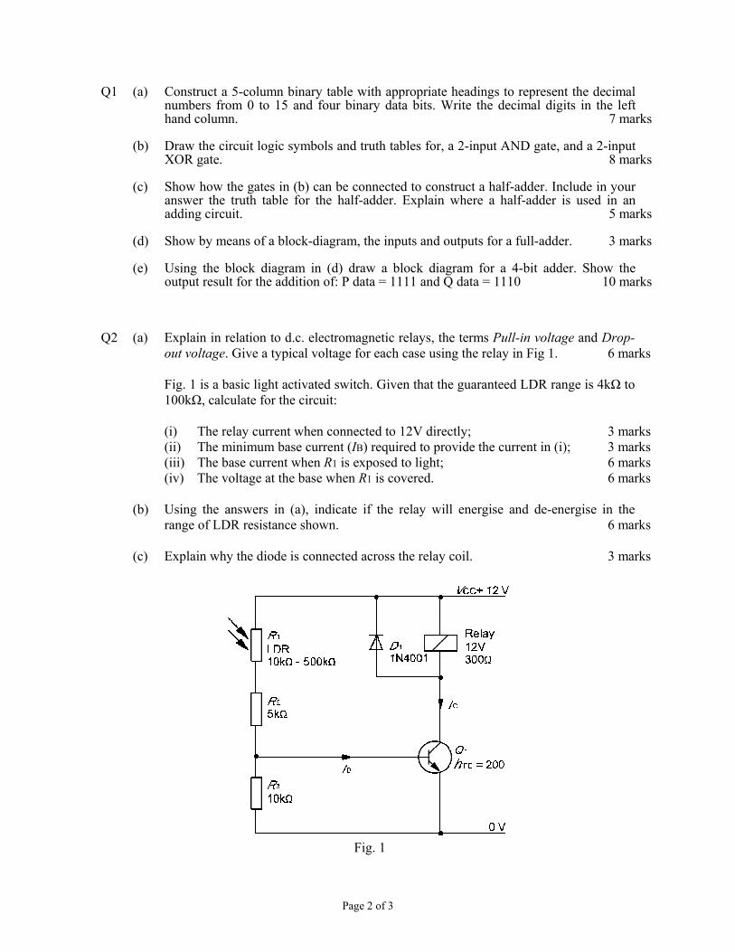
out voltage. Give a typical voltage for each case using the relay in Fig 1. 6 marks Fig. 1 is a basic light activated switch. Given that the guaranteed LDR range is 4kΩ to
100kΩ, calculate for the circuit: (i) The relay current when connected to 12V directly; 3 marks (ii) The minimum base current (IB) required to provide the current in (i); 3 marks (iii) The base current when R1 is exposed to light; 6 marks (iv) The voltage at the base when R1 is covered. 6 marks (b) Using the answers in (a), indicate if the relay will energise and de-energise in the
range of LDR resistance shown. 6 marks (c) Explain why the diode is connected across the relay coil. 3 marks
Fig. 1

Page 3 of 3
Q3 (a) Draw the circuit logic symbols and truth tables for: an inverter, a 2-input AND gate, a 2-input OR gate, and a 2-input XNOR gate. 10 marks
(b) Show how the gates described in (a) can be used to test two binary bits A and B for: (i) A > B (A greater than B) (ii) A = B (A equal to B) (iii) A < B (A less than B) The output result in each test must be 1 when the condition is true. 8 marks (c) Show a combined circuit that will provide an output result of 1 for each of the
following tests. (i) A > B (A greater than B) (ii) A ≥ B (A greater than or equal to B) (iii) A = B (A equal to B) (iv) A ≤ B (A less than or equal to B) (v) A < B (A less than B) The output result must be 1 when the tested condition is true. 15 marks Q4 (a) Given that the transistor in Fig. 2 has an hFE of 250, calculate for the circuit, the
currents IB, IS and IZ. 9 marks (b) Calculate the voltages VB, VE, VCE and also the power dissipated in the transistor. 6 marks
Fig. 2
(c) Identify the transistor circuit configuration and indicate the advantage of using the
transistor in conjunction with the Zener diode. 6 marks (d) Describe the changes in the circuit if the supply voltage falls to 20V and explain the
effect/s this will have on the circuit components. 6 marks (e) Describe the changes in the circuit if the load current rises to 300mA. 6 marks