
MODELING AND CHARACTERIZATION OF ...confsys.encs.concordia.ca/ICCM19/AllPapers/FinalVersion/...THE...
8
THE 19 TH INTERNATIONAL CONFERENCE ON COMPOSITE MATERIALS 1 Introduction Thermoplastic composite materials are available in many forms and are produced by using a variety of manufacturing methods. One of these methods is the stamp-forming. It consists in stamping a preheated flat laminate (or blank) between two heated mold halves defining the part geometry. The modeling of the stamp-forming of thermoplastic composites involves three necessary steps: i) the first step is to determine the deformation mechanisms during the forming process; ii) the second step is to develop or identify a mathematical model that can take into account these mechanisms; iii) the third step is to identify the parameters of the model using different characterization tests performed following standard tests or from recognized approach. 2 Modeling and characterization tests 2.1 Mechanisms of deformations during the forming The mechanisms of deformations in stamp-forming can be split into several ones such as intra-ply, inter- ply and out-of-plane mechanisms [1] as shown in Figure 1. Fig. 1. Primary mechanisms of deformations [1] 2.2 Mathematical model For modeling fabrics impregnated by a viscous fluid, a mathematical model was proposed by Spencer [2]. This model can be used for composites reinforced by two families of fibers. In this model, the Cauchy stress tensor of a Fabric Reinforced Viscous Fluid (FRVF) with two directions of reinforcement has the following form [2]: 1 2 3 4 2 2 2 2 2 a b p T T T σ I A B D A.D D.A B.D D.B C.D D.C C .D D.C (1) where 1 2 3 4 , , , , are viscosities, D the rate of deformation tensor, p the pressure, a T and b T the tensions of fibers respectively in directions a and b (fiber directions), and F the deformation gradient. The viscosities are in general functions of a and b which in turns are related to the angle 2 between the two fiber directions by; cos 2 a.b , (2) The tensors A, B and C are given by: , , , T A a a B b b C a b C b a (3) or under following index forms: , , , T ij i j ij i j ij i j ij i j A aa B bb C ab C ba (4) MODELING AND CHARACTERIZATION OF THERMOPLASTIC COMPOSITES PEEK/CARBON K. Kouwonou 1 , X-T. Pham* 1 and G. Lebrun 2 1 Department of Mechanical Engineering, ETS, Montréal, Canada 2 Department of Mechanical Engineering, UQTR, Trois-Rivières, Canada *corresponding author: [email protected] Keywords: characterization, modeling, thermoplastic composites, forming, finite element.
Transcript of MODELING AND CHARACTERIZATION OF ...confsys.encs.concordia.ca/ICCM19/AllPapers/FinalVersion/...THE...

THE 19TH
INTERNATIONAL CONFERENCE ON COMPOSITE MATERIALS
1 Introduction
Thermoplastic composite materials are available in
many forms and are produced by using a variety of
manufacturing methods. One of these methods is the
stamp-forming. It consists in stamping a preheated
flat laminate (or blank) between two heated mold
halves defining the part geometry. The modeling of
the stamp-forming of thermoplastic composites
involves three necessary steps: i) the first step is to
determine the deformation mechanisms during the
forming process; ii) the second step is to develop or
identify a mathematical model that can take into
account these mechanisms; iii) the third step is to
identify the parameters of the model using different
characterization tests performed following standard
tests or from recognized approach.
2 Modeling and characterization tests
2.1 Mechanisms of deformations during the forming
The mechanisms of deformations in stamp-forming
can be split into several ones such as intra-ply, inter-
ply and out-of-plane mechanisms [1] as shown in
Figure 1.
Fig. 1. Primary mechanisms of deformations [1]
2.2 Mathematical model
For modeling fabrics impregnated by a viscous fluid,
a mathematical model was proposed by Spencer [2].
This model can be used for composites reinforced by
two families of fibers. In this model, the Cauchy
stress tensor of a Fabric Reinforced Viscous Fluid
(FRVF) with two directions of reinforcement has the
following form [2]:
1
2 3
4
2 2
2 2
2
a bp T T
T
σ I A B D A.D D.A
B.D D.B C.D D.C
C .D D.C
(1)
where 1 2 3 4, , , , are viscosities, D the rate of
deformation tensor, p the pressure, aT and bT the
tensions of fibers respectively in directions a and b
(fiber directions), and F the deformation gradient.
The viscosities are in general functions of a and b
which in turns are related to the angle 2 between
the two fiber directions by;
cos2a.b , (2)
The tensors A, B and C are given by:
, , , TA a a B b b C a b C b a
(3)
or under following index forms:
, , , Tij i j ij i j ij i j ij i jA a a B b b C a b C b a
(4)
MODELING AND CHARACTERIZATION OF THERMOPLASTIC COMPOSITES PEEK/CARBON
K. Kouwonou1, X-T. Pham*
1 and G. Lebrun
2
1 Department of Mechanical Engineering, ETS, Montréal, Canada
2 Department of Mechanical Engineering, UQTR, Trois-Rivières, Canada
*corresponding author: [email protected]
Keywords: characterization, modeling, thermoplastic composites, forming, finite element.
where the symbol stands for the tensor product, the superscript T denotes the transpose and a, b
denote the actual fiber directions related to the initial
directions 0a and 0b by
0 0a = F.a b = F.b
(5)
For unidirectional (UD) composites, Eq (1) reduces
to the following formula:
12 2ap T σ I A D A.D+D.A (6)
for which T and 1 L T with L and T
representing the longitudinal and transverse
viscosities respectively. This formulation for
unidirectional composites is called the Ideal Fibre
Reinforced Newtonian fluid Model (IFRM) in the
literature.
2.3 Material characterization and identification of
material parameters
To obtain the model parameters, laminates made of
unidirectional PEEK-carbon CETEX TC1200
lamina from TenCate have been used. The
parameters of the material model must be
determined by a series of experimental tests of
characterization and identification procedure (for
example, fitting method). Aniform™ the finite
element software for composite forming, needs four
kinds of material properties: (i) the modulus of
elasticity of fibers, (ii) the mechanical behaviour of
the matrix (iii) the friction coefficient between a ply
and the tool surface and in between two plies and
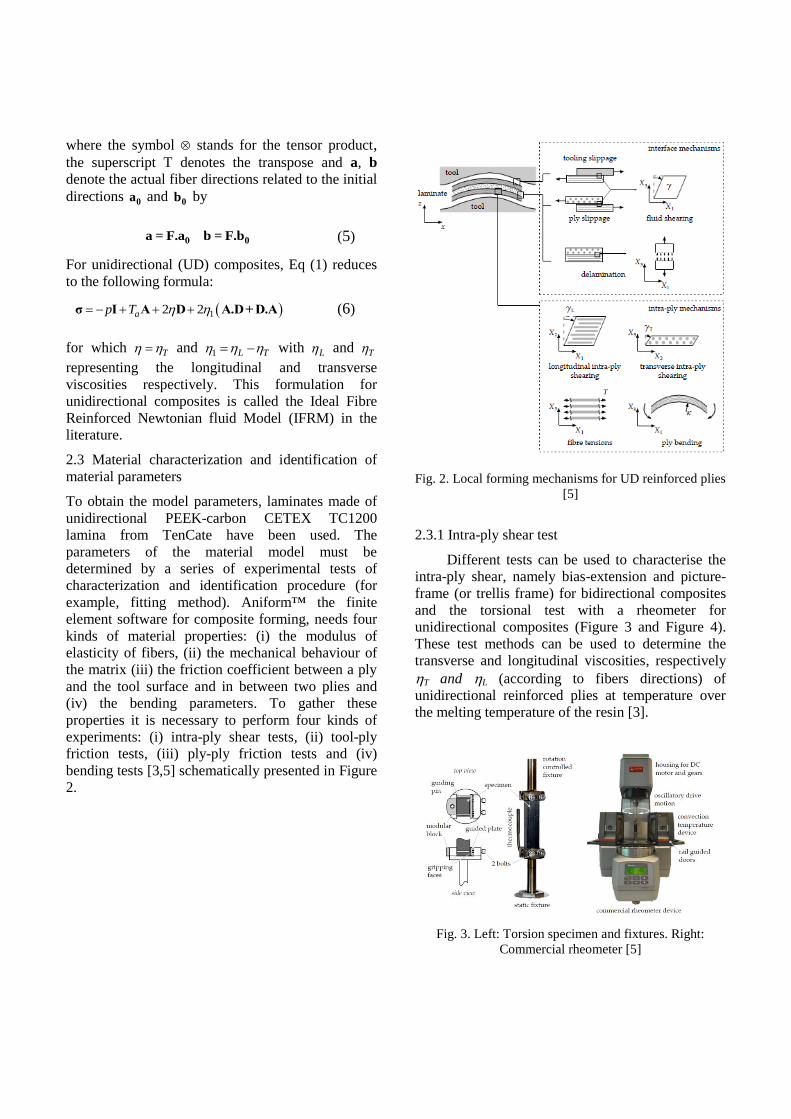
(iv) the bending parameters. To gather these
properties it is necessary to perform four kinds of
experiments: (i) intra-ply shear tests, (ii) tool-ply
friction tests, (iii) ply-ply friction tests and (iv)
bending tests [3,5] schematically presented in Figure
2.
Fig. 2. Local forming mechanisms for UD reinforced plies
[5]
2.3.1 Intra-ply shear test
Different tests can be used to characterise the
intra-ply shear, namely bias-extension and picture-
frame (or trellis frame) for bidirectional composites
and the torsional test with a rheometer for
unidirectional composites (Figure 3 and Figure 4).
These test methods can be used to determine the
transverse and longitudinal viscosities, respectively
T and L (according to fibers directions) of
unidirectional reinforced plies at temperature over
the melting temperature of the resin [3].
Fig. 3. Left: Torsion specimen and fixtures. Right:
Commercial rheometer [5]
3
Fig. 4. Left and center, axial intra-ply shear; right,
transverse intra-ply shear [4]
Some results of torsion tests on a laminate made of
unidirectional PEEK/Carbon plies are presented by
Haanappel [5]. In his study, only the longitudinal
viscosity was determined at high temperature (L =
300 kPa-s at 390°C). The transverse viscosity was
missing due to the deconsolidation of the sample at
high temperature.
For the simulation with AniformTM
, it will be
supposed that either the transverse viscosity is the
same as the longitudinal viscosity (in this case, the
fiber-matrix interactions are not taken into account)
or the longitudinal viscosity is double the value of
the transverse viscosity (in this case, the fiber-matrix
interactions are taken into account) (Table 1).
Table 1. Parameters from intra-ply mechanisms
Case 1 Case 2
L 300 kPa-s L 600 kPa-s
T 300 kPa-s T 300 kPa-s
2.3.2 Tool-ply and ply-ply friction tests
Different set-ups for the characterization of tool-ply
and ply-ply friction have been developed by several
research groups [3]. For the friction characterization,
the set-up from ThermoPlastic Research Center
(TPRC) in the Netherlands is used (Figure 5).
Fig. 5. Left: Tool-ply characterization set-up. Right:
Schematic response that was typically observed [5]
A specimen with typical dimensions of 50x200 mm
was used. The friction coefficient is determined by
the following equation:
2
p
n
F
F
(7)
where Fp is the test force and Fn is the normal force.
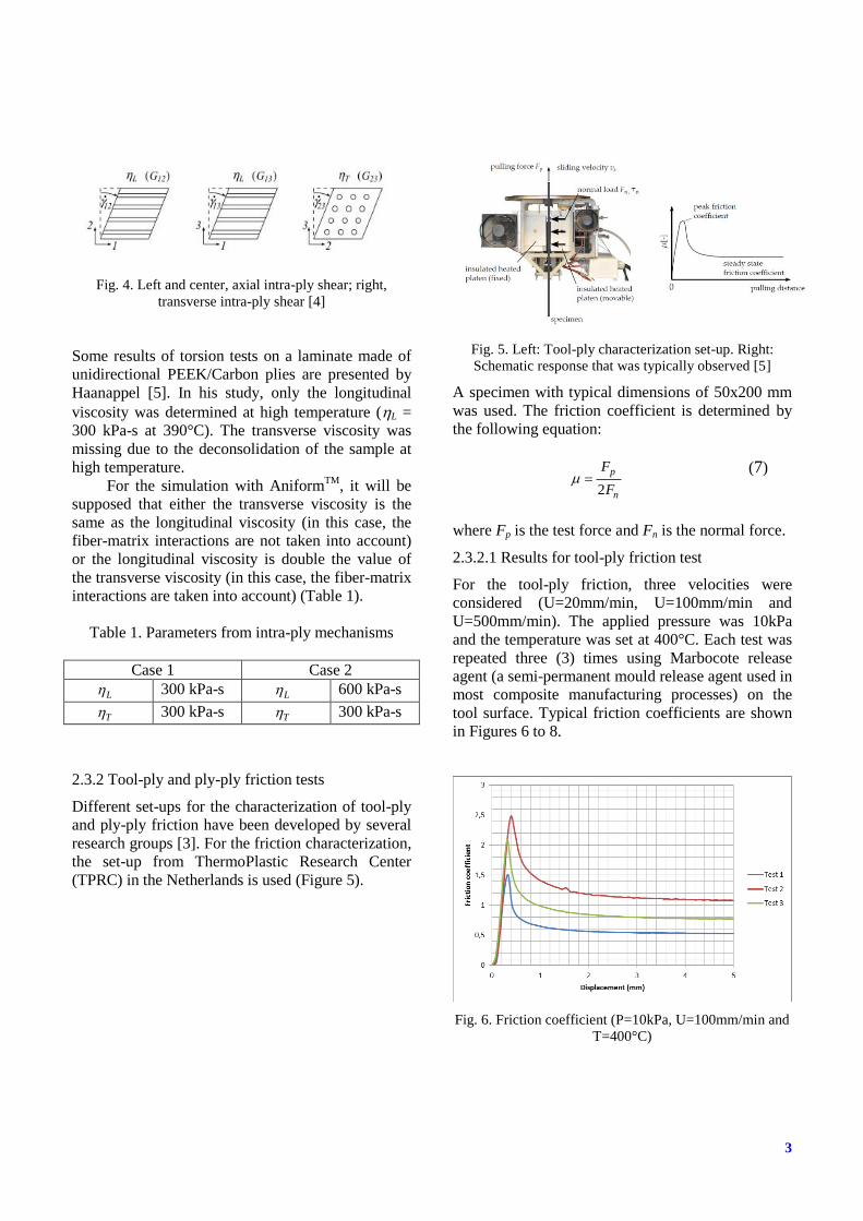
2.3.2.1 Results for tool-ply friction test
For the tool-ply friction, three velocities were
considered (U=20mm/min, U=100mm/min and
U=500mm/min). The applied pressure was 10kPa
and the temperature was set at 400°C. Each test was
repeated three (3) times using Marbocote release
agent (a semi-permanent mould release agent used in
most composite manufacturing processes) on the
tool surface. Typical friction coefficients are shown
in Figures 6 to 8.
Fig. 6. Friction coefficient (P=10kPa, U=100mm/min and
T=400°C)
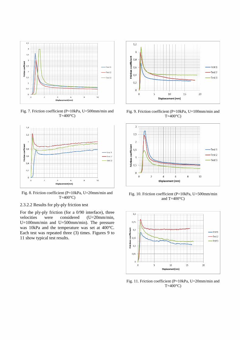
Fig. 7. Friction coefficient (P=10kPa, U=500mm/min and
T=400°C)
Fig. 8. Friction coefficient (P=10kPa, U=20mm/min and
T=400°C)
2.3.2.2 Results for ply-ply friction test
For the ply-ply friction (for a 0/90 interface), three
velocities were considered (U=20mm/min,
U=100mm/min and U=500mm/min). The pressure
was 10kPa and the temperature was set at 400°C.
Each test was repeated three (3) times. Figures 9 to
11 show typical test results.
Fig. 9. Friction coefficient (P=10kPa, U=100mm/min and
T=400°C)
Fig. 10. Friction coefficient (P=10kPa, U=500mm/min
and T=400°C)
Fig. 11. Friction coefficient (P=10kPa, U=20mm/min and
T=400°C)

5
2.3.4 Bending test
For DKT Kirchoff shell element, to improve the
simulation results in Aniform™ [6] in terms of
bending, bending test must be carried out. Two
different types of bending test were performed as
explained below.
2.3.4.1 Three (3) point bending test
Three (3) point bending test was carried out
using Dynamic Mechanical Analysis (DMA)
machine. The tests were performed at 340°C near
the melting temperature of PEEK for the
unidirectional specimen. Typical results are shown
in Figure 12.
Fig. 12. Three (3) point bending test performed in DMA
at 340°C
The flexion modulus was obtained by combining the
storage and loss moduli using the following
relationship:
*
* 2 2
tan
E E iE
E Norm E sqrt E E
E
E
(8)
where :
E : flexion modulus
E’: Storage modulus
E’’: Loss modulus
tan (δ) : Damping factor (or loss factor)
2.3.4.1 Bending test
A bending test performed at TPRC was carried out
using a Rheometer (Figure 3 and Figure 13) at 400
°C.
Fig. 13. Bending fixture in a standard rheometer [5]
In this test [7], the temperature was fixed at 400 °C
and the two (2) different types of velocity were used
(1 rpm and 10 rpm) for 8 plies and 4 plies. Each test
was repeated three (3) times with sample of size 35
mm X 25 mm. Figures 14 to 17 show the test results.

Fig. 14. Bending test (8 plies and 1 rpm)
Fig. 15. Bending test (8 plies and 10 rpm)
Fig. 16. Bending test (4 plies and 1 rpm)
Fig. 17. Bending test (4 plies and 10 rpm)
3 Forming simulation on Aniform™ [6]
A forming simulation was carried out with the mold
and cavity designed by the Université du Québec à
Trois-Rivières (UQTR) using the parameters of the
material model obtained from the characterization
tests presented above. For the simulation, the
laminate was composed of 24 layers ([0/90]12) of
CETEX TC1200 unidirectional PEEK-carbon
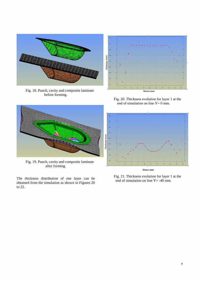
(dimension 240 mm X 160 mm). Figures 18 and 19
show respectively the finite element mesh of the
model (punch and cavity) including the laminate and
the deformed laminate after running the program.
Parameters for simulation below are available in
Table 1 and Table 2.
Table 2. Parameters from inter-ply and out-of-plane
mechanisms
Tool-ply
contact
Ply-ply contact Bending
2 0.9 E 19393
MPa
4 kPa-s 0.329
7
Fig. 18. Punch, cavity and composite laminate
before forming.
Fig. 19. Punch, cavity and composite laminate
after forming.
The thickness distribution of one layer can be
obtained from the simulation as shown in Figures 20
to 22.
Fig. 20. Thickness evolution for layer 1 at the
end of simulation on line Y= 0 mm.
Fig. 21. Thickness evolution for layer 1 at the
end of simulation on line Y= -40 mm.

Fig. 22. Thickness evolution for layer 1 at the
end of simulation on line Y= +40 mm.
4 Conclusion and outlook
To characterize the composite material, one
needs to take into account the intra-ply,
inter-ply and out-of-ply mechanisms of
deformation.
The simulation in Aniform works well with
the parameters measured from the
characterization tests.
The material parameters will be validated by
comparing numerical simulations and
stamp-forming experimental results.
Acknowledgements
The authors would like to thank the industrial
partners, academic partners, various research centers
for their contributions to this study, particularly
CRIAQ, NSERC for financial supports. The authors
wish to especially thank Professor Pascal Hubert,
Professor Remko Akkerman, René Ten Thije,
Sebastiaan Haanappel, the TPRC, the CDCQ, IMI
and AMTC for their support in the realization of this
study.
References
[1] R. Thije and S. Haanappel “Muliti-layer
thermoplastic composites manufacturing processes:
simulations and experiments”. SAMPE Europe
International Conference & Forum, SEICO 2011,
28-30 March 2011, Paris, France.
[2] A.J.M Spencer “Theory of fabric-reinforced viscous
fluid”. Composites, Vol. 31, pp 1311-1321, 2000.
[3] A.C. Long “Composite forming technologies”.
Woodhead publishing in textiles, 2007.
[4] S. Haanappel, R. Thije, and R. Akkerman
“Constitutive modeling of UD reinforced
thermoplastic laminates”. The 10th International
Conference on Flow Processes in Composite
Materials (FPCM10) Monte Verità, Ascona, CH –
July 11-15, 2010.
[5] Haanappel, ir ing Sebastiaan Pieter. « Forming of
UD fibre reinforced thermoplastics ». PhD, 2013.
Enschede, the Netherlands, 161 p. <
http://dx.doi.org/10.3990/1.9789036535014 >.
[6] Ten Thije, René. 2007. « ANIFORM, Version 1.
Logiciel. Netherlands ». < www.aniform.com >. Consulté le 18 octobre 2012.
[7] C.H. Ten Hove. “Bending of CF/PEEK prepregs”.
Master’s thesis. University of Twente, 2012.


![MODELING STRUCTURAL BEHAVIOUR OF PVC …confsys.encs.concordia.ca/ICCM19/AllPapers/FinalVersion/...absorption of circular CFRP tubes with diameter/thickness ratio [7] (b) Photograph](https://static.fdocuments.us/doc/165x107/5adb09867f8b9a6d318d8ddd/modeling-structural-behaviour-of-pvc-of-circular-cfrp-tubes-with-diameterthickness.jpg)

