
ROTORDYNAMICS OF TAPERED COMPOSITE...
12
1. Introduction In the aerospace and automotive applications driveshafts are manufactured using fiber reinforced composite materials. During the design stage of the driveshaft, it is essential to determine the natural frequencies and the critical speeds of the driveshaft such that the resonance phenomena can be avoided. Compared to a conventional metallic driveshaft, a composite driveshaft gives higher natural frequencies and critical speeds, and lower vibration. In addition, they are also lightweight structures, especially when they are tapered. The design of the driveshaft is dependent on its fundamental natural frequency, and tapering the driveshaft can substantially improve the value of this natural frequency. Zinberg and Symonds [1] experimentally performed rotordynamic analysis of advanced composite shaft, and they determined the critical speeds of the composite shaft; the results showed superiority of the composite shafts over the aluminum alloy shafts. Ingle and Ahuja [2] designed an experimental set-up to investigate the vibration of a high speed composite shaft in aerostatic conical journal. Based on a first-order shear deformable beam theory, Chang et al. [3] developed equations of motion of uniform composite shaft using Hamilton’s principle. They performed rotordynamic analysis to find out the natural frequencies and critical speeds. Moreover, Chang et al. [4] studied the vibration of the rotating composite shafts containing randomly oriented reinforcements. Librescu et al. [5] studied the stability of rotating tapered composite shaft subjected to an axial compressive force; the results showed that tapering the composite shaft shifts the domain of divergence and flutter instability to larger rotating speeds. Moreover, Boukhalfa and Hadjoui [6] analyzed the free vibration of uniform composite shaft using the hierarchical finite element method. Al Muslmani and Ganesan [7] developed a finite element model for rotordynamic analysis of uniform composite shaft using Hermitian – conventional finite element. Qatu and Iqbal [8] provided the exact solution for a two-segmented composite driveshaft joined by a hinge. Kim et al. [9] studied the effect of steel core on the bending natural frequency of steel / CFRP hybrid shafts. Kim et al. [10] developed a mechanical model for a tapered composite Timoshenko shaft. The model represented an extended length tool holder at high speed in end milling or boring operation. The structure of the shaft had clamped – free supports. They used the general Galerkin method to obtain the spatial solutions of the equations of motion. They studied forced torsional vibrations, dynamic instability, forced vibration response, and static strength of a tapered composite shaft subjected to deflection- dependent cutting forces. In the present paper, a finite element model for tapered composite driveshaft using Lagrangian finite element formulation is developed for rotordynamic analysis. The strain and kinetic energy expressions for tapered composite driveshaft are obtained and then the Lagrange’s equation is applied to develop the governing equations. Timoshenko beam theory is adopted, so that the effect of shear deformation is included in the model in addition to the effects of the rotary inertia, the gyroscopic forces, the taper angle, the axial load, and the coupling effects due to the lamination of composite layers. 2. Rotordynamic Analysis Figure 1 shows a single lamina deformed into a conical tube with taper angle α that can change functionally in x direction. The principal material directions are denoted by 1, 2, and 3. The axis 1’ extends along the tapered tube surface while 3’- axis ROTORDYNAMICS OF TAPERED COMPOSITE DRIVESHAFT BASED ON A LAGRANGIAN FINITE ELEMENT M. Al Muslmani 1 , R. Ganesan 2 * Department of Mechanical and Industrial Engineering, Concordia University, Montreal, Canada * Corresponding author ([email protected] ) Keywords: (Tapered composite shaft, Rotordynamics, Finite element method)
Transcript of ROTORDYNAMICS OF TAPERED COMPOSITE...

1. Introduction In the aerospace and automotive applications
driveshafts are manufactured using fiber reinforced
composite materials. During the design stage of the
driveshaft, it is essential to determine the natural
frequencies and the critical speeds of the driveshaft
such that the resonance phenomena can be avoided.
Compared to a conventional metallic driveshaft, a
composite driveshaft gives higher natural
frequencies and critical speeds, and lower vibration.
In addition, they are also lightweight structures,
especially when they are tapered. The design of the
driveshaft is dependent on its fundamental natural
frequency, and tapering the driveshaft can
substantially improve the value of this natural
frequency.
Zinberg and Symonds [1] experimentally performed
rotordynamic analysis of advanced composite shaft,
and they determined the critical speeds of the
composite shaft; the results showed superiority of
the composite shafts over the aluminum alloy shafts.
Ingle and Ahuja [2] designed an experimental set-up
to investigate the vibration of a high speed
composite shaft in aerostatic conical journal. Based
on a first-order shear deformable beam theory,
Chang et al. [3] developed equations of motion of
uniform composite shaft using Hamilton’s principle.
They performed rotordynamic analysis to find out
the natural frequencies and critical speeds. Moreover,
Chang et al. [4] studied the vibration of the rotating
composite shafts containing randomly oriented
reinforcements. Librescu et al. [5] studied the
stability of rotating tapered composite shaft
subjected to an axial compressive force; the results
showed that tapering the composite shaft shifts the
domain of divergence and flutter instability to larger
rotating speeds. Moreover, Boukhalfa and Hadjoui
[6] analyzed the free vibration of uniform composite
shaft using the hierarchical finite element method.
Al Muslmani and Ganesan [7] developed a finite
element model for rotordynamic analysis of uniform
composite shaft using Hermitian – conventional
finite element. Qatu and Iqbal [8] provided the exact
solution for a two-segmented composite driveshaft
joined by a hinge. Kim et al. [9] studied the effect of
steel core on the bending natural frequency of steel /
CFRP hybrid shafts. Kim et al. [10] developed a
mechanical model for a tapered composite
Timoshenko shaft. The model represented an
extended length tool holder at high speed in end
milling or boring operation. The structure of the
shaft had clamped – free supports. They used the
general Galerkin method to obtain the spatial
solutions of the equations of motion. They studied
forced torsional vibrations, dynamic instability,
forced vibration response, and static strength of a
tapered composite shaft subjected to deflection-
dependent cutting forces.
In the present paper, a finite element model for
tapered composite driveshaft using Lagrangian finite
element formulation is developed for rotordynamic
analysis. The strain and kinetic energy expressions
for tapered composite driveshaft are obtained and
then the Lagrange’s equation is applied to develop
the governing equations. Timoshenko beam theory is
adopted, so that the effect of shear deformation is
included in the model in addition to the effects of the
rotary inertia, the gyroscopic forces, the taper angle,
the axial load, and the coupling effects due to the
lamination of composite layers.
2. Rotordynamic Analysis
Figure 1 shows a single lamina deformed into a
conical tube with taper angle α that can change
functionally in x direction. The principal material
directions are denoted by 1, 2, and 3. The axis 1’
extends along the tapered tube surface while 3’- axis
ROTORDYNAMICS OF TAPERED COMPOSITE DRIVESHAFT
BASED ON A LAGRANGIAN FINITE ELEMENT
M. Al Muslmani1, R. Ganesan
2*
Department of Mechanical and Industrial Engineering, Concordia University, Montreal, Canada
* Corresponding author ([email protected])
Keywords: (Tapered composite shaft, Rotordynamics, Finite element method)

x
y
z
1
η
2 3,3'
1'
2'
z
y
x
rθ
τxrτxθ
α
σxx
α
α
1'
3'
x
er
2', eθ
1'
Fig. 1. Single composite lamina deformed into tapered cylinder
axis is perpendicular to the same surface. The fiber
angle ƞ is the angle between 1-axis and 1’-axis and
the angle between 2-axis and 2’-axis.
2.1. Stress-Strain relationship for tapered
composite shaft To obtain the stress-strain relations of tapered tube
lamina in cylindrical coordinate system (x, θ, r),
transformation from the principal material
coordinate system (1, 2, 3) to cylindrical coordinate
system (x, θ, r) must be done. To do this, it is
necessary to apply sequence of transformations as in
the following:
1) ƞ about 3-axis in principal material
coordinate system (1, 2, 3).
2) α about 2’-axis in primed coordinate system
(1’, 2’, 3’).
The stress-strain relations for a lamina in the
principal material directions are
(1)
where [Q] is the stiffness matrix of a single lamina.
After performing the rotation ƞ about 3-axis in
principal material coordinate system (1, 2, 3), the
relation between stresses and strains in primed
coordinate system (1’, 2
’, 3’) can be written as:
(2)
where ] is the transformed stiffness of the layer
and can be calculated by the following equations
(3)
where
(4)
(5)
m = cos ƞ ; n = sin ƞ (6)
By considering the rotation α about 2’-axis in primed
coordinate system (1’, 2
’, 3
’), the stress-strain
relation in cylindrical coordinate system (x, , r) can
be written as
(7)
where is the transformed stiffness of the layer
and can be calculated by the following equation :
(8)
where
(9)

(10)
c = cos α ; s = sin α (11)
2.2. Strain-displacement relations
Timoshenko beam theory is considered here to study
the transverse vibration of the composite shaft. So,
the displacement fields of the composite shaft are
assumed as
(12)
(13)
(14)
where and . ,
are the displacements of any point of the composite
shaft in x, y and z directions, and are the
displacements of a point on the reference axis of the
shaft in y and z directions and and are the
rotation angles of the cross-section about y-axis and
z-axis. Using Equations (15) - (17), the strains can
be obtained as
(15)
(16)
(17)
(18)
(19)
(20)
The strain components in cylindrical coordinate
system (x, θ, r) can be written in terms of the strains
in the Cartesian coordinate system (x, y, z) as
(21)
where and . Substituting
Equations (18) – (19) into Equation (24), one can get
(22)
(23)
(24)
(25)
(26)
(27)
In Timoshenko beam theory, the shear correction
factor is used to adjust the stress state. By
considering Equations (26) – (28) and introducing
the shear correction factor , the stress – strain
relations in Equation (9) can be expressed as
(28)
2.3. Kinetic and Strain energy expressions
Since the mass, the diametral mass moment of
inertia and the polar mass moment of inertia of a
tapered composite shaft change with respect to the
axial coordinate x of the shaft, the kinetic energy for
tapered composite shaft is

(29)
where , , are the mass per unit length,
diametral mass moment of inertia, and polar mass
moment of inertia.
(30)
(31)
(32)
where n is the number of the layers in the laminate,
and is the density of the layer. are the
outer radius and inner radius of the s-th layer. For
conical shape, the inner radius and outer radius are
(33)
(34)
where , , , and are the inner and outer
radii and they are defined in Figure 2.
x
ri1ri2ro1
ro2
Fig.2. Typical tapered shaft element
The strain energy of tapered composite shaft due to
bending moments and shear forces is
(35)
Considering Equations (25) - (30) the strain energy
can be written as
(36)
where
(37)
(38)
(39)
(40)
(41)
(42)
(43)
(44)
After applying the integrations in Equations (40) –
(47), the stress resultants and stress couples of the
tapered composite shaft are
(45)
(46)
(47)
(48)
(49)
(50)
where
(51)
(52)
(53)
(54)
(55)
(56)
(57)
(58)
(59)
The strain energy in Equation (39) represents
the strain energy of the composite shaft that results
from the bending moment and the shear force, but
when the composite shaft is under a constant axial
force, the total strain energy of the composite shaft
is
(60)
where is the external work done on the shaft due
to a constant axial force P and can be written as
(61)
2.4. Lagrangian composite shaft element
formulation
The Lagrangian interpolation functions are used here
to approximate the displacement fields of the tapered
composite rotor. Figure 3 shows an element with
three nodes; two nodes are at the ends of the element
and one node is at the centre of the element. Each
node has four degrees of freedom, two translational
in y and z directions and two rotational about y and z
axes. The shape functions that are used to
approximate field solution are
(62)
(63)
(64)
1 2 3
L
L/2
Fig.3. Beam element with three nodes
Thus, the displacement field variables can be written
as:
(65)
(66)
(67)
(68)
After substituting Equations (68) - (71) into the
energy expressions: Equations (32), (39), and (64),
and applying the Lagrange’s equations, one can
obtain the equations of motion of free vibration of
tapered composite driveshaft as
(69)
where

(70)
(71)
(72)
(73)
(74)
(75)
(76)
(77)
(78)
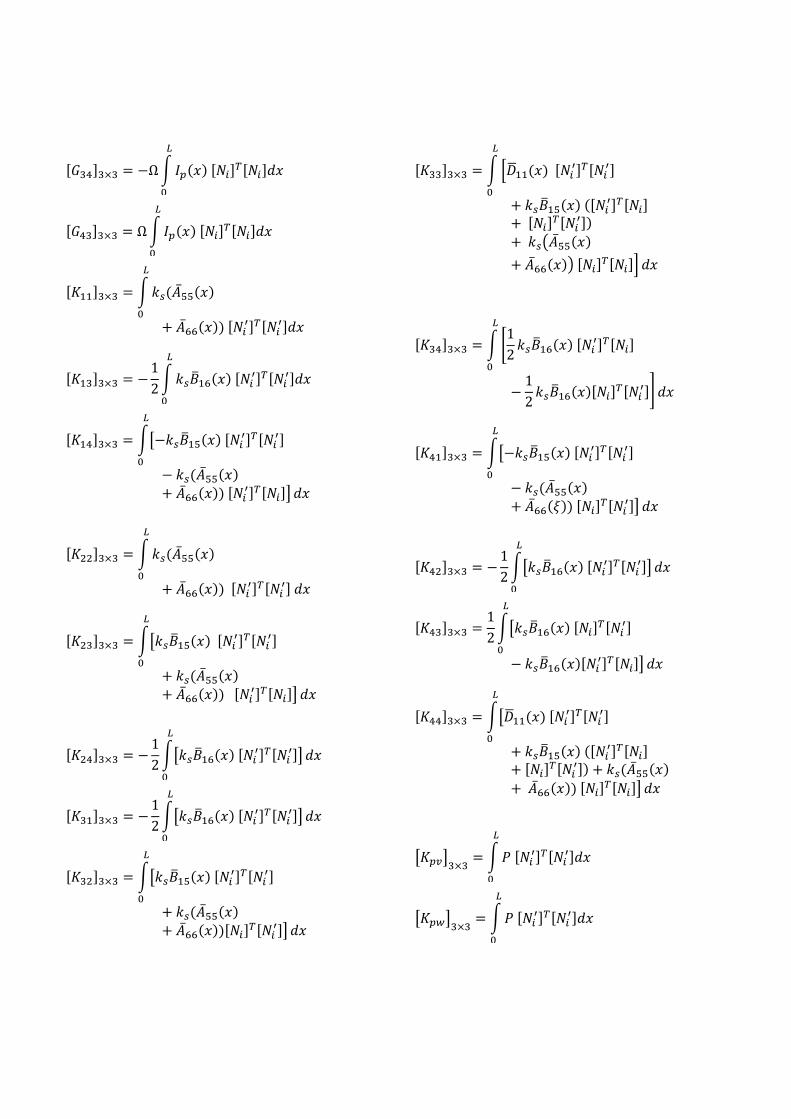
where is the mass matrix, is gyroscopic
matrix, is the stiffness matrix, and is the
geometric stiffness matrix due to axial load. The
detailed expressions of the sub-matrices are given in
the appendix.
3. Validation In the following example, the fundamental natural
frequency and first critical speed of the tapered
composite shaft are studied using finite element
method and the Rayleigh-Ritz method. In this
analysis, a hollow tapered composite shaft made of
graphite-epoxy lamina is considered. The shaft is
simply supported at the ends; the outer diameter of
the composite shaft at the left end is 12.69 cm while
the outer diameter at the right end increases with
changing the taper angle. The outer diameter of the
composite shaft at the left end is constant for all the
taper angles. Figure 4 shows the configuration of the
tapered graphite - epoxy composite shaft. The
properties of the graphite-epoxy composite material
are listed in Table 1. The wall thickness of the
tapered composite shaft is 1.321 mm, and the
composite shaft is made of ten layers, each with the
same thickness. In addition, the configuration of the
composite shaft is [90o/45
o/-45
o/0
o6/90
o] and the lay-
up starts from the inside. The total length of the
composite shaft is 2.47 m. The correction factor ks
for the composite shaft at the zero taper angle is
0.503, yet this value is considered for all taper
angles in this example.
Table 1 Properties of the composite materials
Properties Boron-epoxy Graphite-epoxy
E11 (GPa) 211 139
E22 (GPa) 24 11
G12 = G13 (GPa) 6.9 6.05
G23 (GPa) 6.9 3.78
ν12 0.36 0.313
Density (Kg/m3) 1967 1578
Fig.4. The configuration of the tapered graphite - epoxy
composite shaft
Twenty elements with equal length are used for the
analysis. The same number of elements was used for
all the taper angles. In Rayleigh-Ritz method, five
Ritz terms were used. The first critical speeds of the
tapered composite shaft calculated using the finite
element model are illustrated in Table 2 beside the
speeds obtained using the Rayleigh-Ritz solution. It
can be seen from Table 2 that the difference is small
between the present model and the Rayleigh-Ritz
solution in obtaining the first critical speed. The
difference does not exceed 4% between them in
obtaining the first critical speed when the taper angle
is 4o.
Another observation from Table 2 is that the critical
speed of the composite shaft increases when
increasing the taper angle, because the
circumference of the cross-section increases through
the length of the shaft from the left end to the right
end when increasing the taper angle. This means the
amount of composite material increases through the
length of the shaft when increasing the taper angle,
which makes the tapered composite shaft stiffer than
the uniform composite shaft. The natural frequencies
of the tapered composite shaft are shown in Table 3;
the results were obtained at 10,000 rpm and the
results obtained by finite element model are
comparable with the results predicted using the
Rayleigh-Ritz method.
Table 2 First critical speed in rpm of the tapered
composite shaft with different taper angles using finite
element method and Rayleigh-Ritz method
Taper
angle
Lagrangian
finite element
Rayleigh-Ritz
method
0o
5219 5220
1o
6645 6667
2o
7718 7820
3o
8525 8772
4o
9121 9510
Table 3 The natural frequencies in Hz of the tapered
composite shaft at 10000 rpm with different taper angles
obtained using finite element method and Rayleigh-Ritz
method.
Taper
angle Mode
Lagrangian
finite element
Rayleigh-
Ritz method
0o
BW1 86 87
FW1 87 88
BW2 316 316
FW2 319 319
1o
BW1 110 110
FW1 112 112
BW2 386 386
FW2 390 389
2o
BW1 128 130
FW1 131 132
BW2 436 436
FW2 440 441
3o
BW1 142 146
FW1 145 149
BW2 472 473
FW2 476 477
4o
BW1 152 159
FW1 157 163
BW2 499 500
FW2 502 504
4. Numerical examples In this example, rotordynamic analysis of the
tapered composite shaft is conducted. The tapered
composite shaft has a disk at its mid-length and two
bearings at the ends; the configuration of the tapered
composite shaft is illustrated in Figure 5. The shaft
is made of a graphite-epoxy composite material, and
the geometric properties of the composite shaft are
given in Table 4. Different taper angles are
considered in the analysis. The inner and outer
diameters at the left end of the shaft do not change
with changing the taper angle, while at the right end
they increase when increasing the taper angle. The
tapered composite shaft is modeled by twenty
elements of equal length.
Fig.5. The configuration of the tapered composite shaft
with a disk at its mid-length
Table 4 The geometric dimensions and properties of the
tapered composite shaft
Composite Shaft
Inner diameter ,ID = 0.028 m
Outer diameter ,OD = 0.048m
Length, L = 0.72 m
Lay-up from inside
[90/45/-45/06/90]
Shear correction factor, = 0.56
Disk
Mass = 2.4364 Kg
Diametral mass moment of inertia,
Id = 0.1901 Kg.m2
Polar mass moment of inertia,
Ip = 0.3778 Kg.m2
Bearing
Kyy = Kzz = 17.5 MN/m
Czz = Cyy = 500 N.s/m
Table 5 shows the first critical speeds of the tapered
composite shaft for different taper angles, and it can
be seen from the table that the first critical speed
increases when increasing the taper angle. However,
Figure 6 shows that the increase in the first critical
speed when increasing the taper angle does not
continue because the first critical speed reaches its
maximum at 10o taper angle and then starts to drop
off when increasing the taper angle; to understand
why this happens, one needs to return to Equations
(51) – (59) and to look at Figure 7.The equations
represent the matrix that depends on the
stiffness and the radius of the layer. Whereas, Figure

7 represent the material stiffnesses for each single
layer of the tapered composite shaft; from the
figures it is clear that is much higher than
and for all the layers and the taper
angles, and decreases with increasing the taper
angle except for the layer with fiber orientation of
90o. Consequently, in Figure 6, the inner and the
outer radii of the layer control the first critical speed
for taper angle of while controls
the first critical speed for taper angle of .
Table 5 The first critical speed in rpm of the tapered
composite shaft for different taper angles. Taper angle Lagrangian finite element solution
0o
7328
1o
9772
2o
11551
3o
12912
4o
13935
Fig. 6. The first critical speeds of the tapered composite
shaft for different taper angles
Moreover, the effect of the disk position on the first
critical speed is studied. Figure 8 shows the tapered
composite shaft with different disk positions. Table
6 illustrates the first critical speed of the tapered
composite shaft for different disk positions and taper
angles. For taper angles of 0o
and 1o the maximum
value of the first critical speed happens when the
position of the disk is located at the center, while for
taper angles between 2o and 4
o the maximum value
of the critical speed happens when the disk is located
at a distance of 4L/10 from the left end. It can be
said for high taper angles that the critical speed
reaches its maximum as the disk approaches the left
bearing where the inner and outer diameters are
smaller than that at the right end.
Fig. 7. and for the layer of
graphite-epoxy with fiber orientation angle of 0o
3L/10
4L/10
5L/10
Figure 8 Tapered composite shaft with different positions
of the disk. Furthermore, the effect of the stacking sequence of
the layers on the first critical speed of the tapered
composite shaft is analyzed. Table 7 illustrates the
first critical speed for different stacking sequences
and taper angles. The lay-up for the layers starts
from inside, and there are ten layers with four
different fiber orientation angles. The layers near the
outer surface have larger circumferences and
volumes than those near the inner surface of the
shaft, and they resist more bending moment than
those layers that are nearer to the inner surface; as a
result, the outer surface layers control the stiffness of
the shaft. Consequently, it can be observed from
Table 7 that laying up the layers that have high
stiffness near the outer side of the shaft increases the
critical speed. For example, at a taper angle of 4o,
the first critical speed of the configuration [06o
/90o/45
o/-45
o/90
o] is 13474 rpm, and in this
configuration the layers that have fiber orientation of
0 2 4 6 8 10 12 14 16 18 200.7
0.8
0.9
1
1.1
1.2
1.3
1.4
1.5
1.6x 10
4
Taper angle, degrees
Fir
st
cri
tical
sp
eed
, rp
m
0o are laid up on the inner side of the shaft. The
layers with fiber orientation of 0o have higher
stiffness than other layers, so laying them up near
the outer surface increases the critical speed. Thus,
the configuration [90o/45
o/-45
o/90
o/06
o], where the
layers with 0o fiber orientation are laid-up on the
outer side of the shaft, has higher first critical speed
than the other configurations in Table 7. Moreover,
it can be observed from the Table 6 that the
difference between the first critical speeds of the
configurations A and E decreases when increasing
the taper angle; for example, at 00, 2
o, and 4
o the
differences in first critical speeds between the
configurations A and E are 19%, 9.4%, and 5.1%,
respectively. This is an indication that increasing the
taper angle eliminates to some extent the effect of
stacking sequence on the first critical speed and the
natural frequencies.
Table 6 First critical speed in rpm of the tapered
composite shaft for different taper angles and positions of
the disk
Taper
angle
The position of the disk
3L/10 4L/10 5L/10 6L/10 7L/10
0o
5748 6602 7328 6602 5748
1o
8144 9570 9760 8889 8159
2o
10448 12011 11537 10829 10273
3o
12532 13511 12903 12405 12033
4o
14224 14408 13935 13639 13440
5o
15285 15002 14699 14573 14527
In the following example, the effect of the axial load
on natural frequencies of tapered composite shaft is
studied. The tapered composite shaft is fixed by a
bearing at one end and is free at the other end. The
shaft is made of boron-epoxy composite material,
and the properties of the composite material are
listed in Table 1. The tapered composite shaft is
made of ten layers, and the thickness of each layer is
0.25 mm. The configuration is [90o/45
o/-45
o/0
o6/90
o].
Also, the length of the shaft L is 0.5 m and the inner
diameter di at the free end is 1 cm. The tensile and
compressive loads are applied at the free end of the
tapered composite shaft, and the compressive loads
are less than the buckling loads. The effect of
applying the tensile and the compressive loads on
the first natural frequencies of the tapered composite
shaft is illustrated in Table 8 and Table 9. According
to the results in the tables, the tensile load increases
and the compressive load decreases the natural
frequency. This is because the tensile load increases
the stiffness of the tapered composite shaft, while
the compressive load decreases it. In addition,
increasing the taper angle increases the natural
frequency and the first critical speed for both the
tensile and compressive loads.
In addition, the effect of the length on the first
critical speed of the tapered composite shaft is
studied. Figure 9 shows the configuration of the
tapered composite shaft with different lengths. The
length of the tapered composite shaft changes from
L to 0.7 L by 10 percent every time, the first critical
speeds were obtained for different taper angles for
each length. The inner diameter at the free end of the
tapered composite shaft is kept at 1 cm, whereas the
inner diameter of the other end changes with the
changing taper angle and length.
L
0.9 L
0.8 L
0.7 L
Figure 9 Different lengths of the tapered composite shaft.
Figure 10 shows the first critical speeds for different
lengths. One can observe from the figure that the
first critical speed increase either when the
length decreases or when the taper angle
increases. Also, the difference between the first
critical speeds increases with an increasing taper
angle. For example, at 5o taper angle the difference
between the first critical speed of the length L and
length 0.7L is higher than the difference at 0o taper
angle.
Moreover, the effect of the bearing’s stiffness on the
first critical speed is illustrated in Figure 11.The
stiffness of the bearing varies from 0.01 MN/m to 10
GN/m. The figure shows that, at low bearing
stiffness, increasing the taper angle decreases the
first critical speed; despite the fact that, at high
bearing stiffness, increasing the taper angle increases
the first critical speed. In addition, it can be observed
from the figure that at a small taper angle the
required stiffness for the bearing to be considered as

simply supported condition, which is the condition
that increasing the stiffness of the bearing does not
affect the first critical speed and the natural
frequencies any more, is lower than the stiffness
required for the bearing at large taper angle
Figure 10 First critical speeds for different lengths
Figure 11 First critical speeds for different bearing
stiffness values
Table 7 The first critical speed in rpm of the tapered composite shaft for different taper angles and stacking sequences
determined using Lagrangian finite element model
Configuration Stacking sequence Taper angle, degrees
0o
1o
2o
3o
4o
A [06o /90
o/45
o/-45
o/90
o] 6475 8962 10848 12333 13478
B [90o/06
o /45
o/-45
o/90
o] 6821 9308 11166 12613 13718
C [90o/45
o/06
o /-45
o/90
o] 7060 9530 11354 12758 13823
D [90o/45
o/-45
o/06
o/90
o] 7328 9772 11551 12912 13935
E [90o/45
o/-45
o/90
o /06
o] 7707 10129 11868 13184 14167
Table 8 Natural frequencies in Hz of the tapered composite shaft at 5000 rpm with different tensile loads
Tensile Load
(KN) Mode
Taper angle, degrees
0o
1o
2o
3o
4o
5o
1 BW1 433 744 1027 1274 1484 1659
FW1 434 746 1029 1276 1486 1662
9 BW1 545 802 1064 1301 1504 1675
FW1 546 803 1066 1303 1507 1677
Table 9 Natural frequencies in Hz of the tapered composite shaft at 5000 rpm with different compressive loads
Compressive
Load (KN) Mode
Taper angle, degrees
0o
1o
2o
3o
4o
5o
1 BW1 398 729 1018 1268 1479 1655
FW1 398 731 1019 1270 1481 1658
9 BW1 214 662 977 1240 1459 1639
FW1 214 663 979 1242 1461 1641

5. Conclusion In this study a finite element model is developed for
the rotordynamic analysis of the tapered composite
shaft. The model is developed using the Lagrangian
finite element formulation and based on Timoshenko
beam theory. The effects of rotary inertia, transverse
shear deformation, gyroscopic force, axial load,
coupling due to the lamination of composite layers,
and taper angle are taken into account. In order to
validate the finite element model, Rayleigh - Ritz
method is used to obtain an approximate solution for
simply-supported tapered composite shaft.
Numerical example are given, and it is found that
the bending natural frequencies and first critical
speeds, for different taper angles of the tapered
composite shaft, determined using Rayleigh-Ritz
method are in agreement with those obtained using
finite element model. In this work, increasing the
taper angle of the tapered composite shaft means
that the inner and outer diameters at one end are
constant while the inner and outer diameters at the
other end increase with increasing the taper angle.
Consequently, it is found that increasing the taper
angle increases the bending natural frequencies and
first critical speed of the tapered composite shaft.
However, it is seen through the numerical results
that this direct relationship between the first critical
speed and the taper angle does not sustain because
the first critical speed reaches its maximum value at
10o and then starts to drop-off with increasing the
taper angle.
References
[1] Zinberg, H. and Symonds, M.F., "The
Development of an Advanced Composite Tail
Rotor Driveshaft," The 26th Annual Forum of
the American helicopter Society, Washington,
DC, June 1970.
[2] Ingle, R.B. and Ahuja, B.B. "An experimental
investigation on dynamic analysis of high speed
carbon–epoxy shaft in aerostatic conical journal
Bearings," Composites Science and Technology,
Vol. 66, pp.604–612, 2006.
[3] Chang, M.-Y. Chen, J.-K. and Chang, C.-Y. , " A
simple spinning laminated composite shaft
model". International Journal of Solids and
Structures, Vol.41, pp.637–662, 2004.
[4] Chang, M.-Y. Huang, J. H. and Chang, C.-Y. , "Vibration analysis of rotating composite shafts
containing randomly oriented reinforcements,"
Composite structures, Vol.63, pp.21–32, 2004.
[5] Na, S. Yoon, H. and Librescu, L., "Effect of taper
ratio on vibration and stability of a composite
thin-walled spinning shaft,” Thin-Walled
Structures, Vol.44, pp.362–371, 2006.
[6] Boukhalfa, A. and Hadjoui, A., "Free vibration
analysis of a rotating composite shaft using the
p-version of the finite element method,"
International Journal of Rotating Machinery,
2008, pp. 10. Article ID 752062.
[7] Al Muslmani M. and Ganesan, R., "Rotor-
Dynamics of Stepped Composite Shaft - Disk
Systems Based on a Conventional Composite
Finite Element," American Society for
Composites 27th Annual Technical Conference,
Arlington, Texas, 2012.
[8] Qatu, M. S. and Iqbal, J., "Transverse vibration of
a two-segment cross-ply composite shafts with a
lumped mass," Composite Structures, Vol.92,
pp. 1126-1131, 2010
[9] Kim W, Argento A, Mohanty PS. "Bending
natural frequencies of circular CFRP shafts with
a metal core or casing," Journal of Composite
Materials, Vol.38, pp.475–94, 2003
[10] Kim, W. Argento, A. and Scott, R. A.," Rotating
tapered composite shafts: forced torsional and
extensional motions and static strength". Journal
of Vibration and Acoustics, Vol.123, 2001.
Appendix


![Improvement of Interfacial Shear Strength Using ...confsys.encs.concordia.ca/ICCM19/AllPapers/FinalVersion/RUT80577.pdf · modified by introducing nano, ... the IFSS [15] and, based](https://static.fdocuments.us/doc/165x107/5abd66f07f8b9a8e3f8bba70/improvement-of-interfacial-shear-strength-using-by-introducing-nano-the.jpg)


