Minimum Energy Requirements in Complex Distillation...
28
Minimum Energy Requirements in Complex Distillation Arrangements by Ivar J. Halvorsen A thesis submitted for the degree of Dr.Ing. May 2001 Department of Chemical Engineering Norwegian University of Science and Technology N-7491 Trondheim, Norway Dr. ing. Thesis 2001:43 ISBN 82-471-5304-1 ISSN 0809-103X
Transcript of Minimum Energy Requirements in Complex Distillation...
NTNU Dr. ing. Thesis 2001:43 Ivar J. Halvorsen
Minimum Energy Requirementsin
Complex Distillation Arrangements
by
Ivar J. Halvorsen
A thesis submitted for the degree of Dr.Ing.
May 2001Department of Chemical Engineering
Norwegian University of Science and Technology
N-7491 Trondheim, Norway
Dr. ing. Thesis 2001:43ISBN 82-471-5304-1
ISSN 0809-103X

2
NTNU Dr. ing. Thesis 2001:43 Ivar J. Halvorsen
prox-port
hichnd useua-
activ-imeshap-wasm of
U,step
howical
ineeres isencengi-
esign,con-with
oc-tentialerly
Preface
The Norwegian Dr.Ing (Ph.D) degree requires a basic research work and apimately one full year of courses at graduate and postgraduate level. This represents the main scientific results from the research.
However, there are also interesting issues on how the results were obtained, ware not covered. Some of these issues are the work progress, development aof computational tools like numerical methods for optimization, nonlinear eqtion solving, simulation and control, and the software itself.
In all basic research, the results themselves cannot be planned for, only theities which may or may not lead up to new results. In this process, we sometdiscover new interesting directions. This applies for the results presented in cters 3-6. The research started out in the direction of optimizing control, but itdiscovered that we were able to find some new basic relationships in a systeintegrated distillation columns, and that thread was followed in more detail.
My background is from the department of Engineering Cybernetics, NTNwhere I graduated in 1982, and for me it have also been interesting to take theinto Chemical Engineering. There are some obvious cultural differences into approach an engineering task. I think it can be summed up in that the chemengineer focuses more on the design of a process, while the control engfocuses more on its operation. Clearly, a combination of these approachneeded. In control engineering, we must look more into the process and influthe design to get more controllable units and plants. It also helps the control eneer to have a basic understanding of the process behaviour. In process dchemical engineers should put more attention to the dynamic properties andtrol technology and use this knowledge to design more compact processesbetter overall performance. I feel that in particular for complex integrated presses, combined focus on process design and operation is vital since the pobenefit of the integration can easily be lost if the process is not propcontrolled.
NTNU Dr. ing. Thesis 2001:43 Ivar J. Halvorsen

4
SIN-anus-
visor,eld.lf in
urduousthes. Ingavetionid,
s andlu-ranechil-eltisit-had
eanol-theionme.
tten-any
I have some years of experience from industry and as a research scientist atTEF, the research foundation at NTNU. Unlike the work at SINTEF, whereindustrial customer usually is directly awaiting the results from a project, the ctomer for the Dr.Ing. has several faces. There is a financial sponsor, a superthe candidate himself and the international community of researchers in the fiIt is clear that the most demanding “customer” has to be the candidate himseorder to obtain the best results.
I have had numerous fruitful discussions with my supervisor, professor SigSkogestad at the Chemical Engineering Department. He has been a continsource of inspiration, and has provided invaluable contributions both inresearch work and to help me focus on the reader during writing of this thesiSkogestad’s process control group Atle C. Christiansen and John Morudimportant inputs on integrated column arrangements, and I will also menBernd Wittgens, Truls Larsson, Audun Faanes, Eva-Katrine Hilmen, Tore LMarius Govatsmark, Stathis Skouras and the latest arrivals Espen StorkaaVidar Alstad. I thank Hilde Engelien for reading the manuscript and giving vaable feedback. I shared an office with Edvard Sivertsen, who studied membseparation, and we discussed everything from thermodynamics to raisingdren. I hope he forgives me for all the lecturing about distillation every time I fthat I had discovered something. I am also grateful for discussions with the ving professors Valeri Kiva (1996/97) and David Clough (1999/2000). We alsothe opportunity to meet Felix Petlyuk who visited Trondheim in May 1997.
As an introduction to Petlyuk arrangements, NTNU participated in a Europresearch project within the Joule 3 programme: DISC, Complex distillation cumns. One spin-off was the visit by Maria Serra in june 1998, resulting inpaper in Chapter 11. I also thank my employer SINTEF for support, in additto the grant from the Norwegian Research Council through the REPP program
Finally I thank my wife Toril, and my children Øyvind, Berit and Maria for givingme a wider perspective on things. The work has consumed a lot of time and ation for some years now and Berit, who is 10 years old, asked me: “How mtheses have you written now? Only one?”
NTNU Dr. ing. Thesis 2001:43 Ivar J. Halvorsen
lla-the
u-eseenta-eenatedtive.trolbeentherbet-
on-bersic
molarpor-ctlysplitce of
tri-ow
e the-for
verifi-, it is
Summary
Distillation is the most widely used industrial separation technology and distition units are responsible for a significant part of the total heat consumption inworld’s process industry. In this work we focus on directly (fully thermally) copled column arrangements for separation of multicomponent mixtures. Thsystems are also denoted Petlyuk arrangements, where a particular implemtion is the dividing wall column. Energy savings in the range of 20-40% have breported with ternary feed mixtures. In addition to energy savings, such integrunits have also a potential for reduced capital cost, making them extra attracHowever, the industrial use has been limited, and difficulties in design and conhave been reported as the main reasons. Minimum energy results have onlyavailable for ternary feed mixtures and sharp product splits. This motivates furresearch in this area, and this thesis will hopefully give some contributions toter understanding of complex column systems.
In the first part we derive the general analytic solution for minimum energy csumption in directly coupled columns for a multicomponent feed and any numof products. To our knowledge, this is a new contribution in the field. The baassumptions are constant relative volatility, constant pressure and constantflows and the derivation is based on Underwood’s classical methods. An imtant conclusion is that the minimum energy consumption in a complex direintegrated multi-product arrangement is the same as for the most difficultbetween any pair of the specified products when we consider the performana conventional two-product column. We also present theVmin-diagram, which isa simple graphical tool for visualisation of minimum energy related to feed disbution. TheVmin-diagram provides a simple mean to assess the detailed flrequirements for all parts of a complex directly coupled arrangement.
The main purpose in the first part of the thesis has been to present a completory of minimum energy in directly coupled columns, not a design procedureengineering purposes. Thus, our focus has been on the basic theory and oncation and analysis of the new results. However, based on these results
NTNU Dr. ing. Thesis 2001:43 Ivar J. Halvorsen

6
ionsana-
t ofs ofcon-ome
r-tationent
le) aimal
is aif we
theper-lievethelate).
, andduct
o usebervery
formnaly-electe. In
t onereammp-ide-
andated
straightforward to develop design procedures including rigorous computatfor real feed mixtures without the idealized assumptions used to deduce thelytic results.
In part 2 we focus on optimization of operation, and in particular the concepself-optimizing control. We consider a process where we have more degreefreedom than are consumed by the product specifications. The remaining unstrained degrees of freedom are used to optimize the operation, given by sscalar cost criterion. In addition there will in practice always be unknown distubances, model uncertainty and uncertainty in measurements and implemenof manipulated inputs, which makes it impossible to precalculate and implemthe optimal control inputs accurately.
The main idea is to achieveself-optimizing controlby turning the optimizationproblem into a constant setpoint problem. The issue is then to find (if possibset of variables, which when kept at their setpoints, indirectly ensures optoperation.
We have used the ternary Petlyuk arrangement to illustrate the concept. Itquite challenging case where the potential energy savings may easily be lostdo not manage to keep the manipulated inputs at their optimal values, andoptimum is strongly affected by changes in feed composition and columnformance. This also applies to the best control structure selection, and we bethat the reported difficulties in control are really a control structure problem (task of selecting the best variables to control and the best variables to manipu
In this analysis we present in detail the properties of the Petlyuk arrangementshow how important characteristics depend on the feed properties and propurity. We have used finite stage-by-stage models, and we also show how tUnderwood’s equations to compute the energy consumption for infinite numof stages for any values of the degrees of freedom. Such computations aresimple. The results are accurate and in terms of computation time, outpersimulations with finite stage-by-stage models by several magnitudes. The asis gives a basic understanding of the column behaviour and we may soperating strategies based on this knowledge for any given separation cassome cases there will be a quite flat optimality region, and this suggests thaof the manipulated inputs may be kept constant. We also show that the side-stpurity has strong impact on the optimality region. One observation is that a sytom of sub-optimal operation can be that we are unable to achieve high sstream purity, and not necessarily increased energy consumption.
In summary, the presented results contribute to improved understandingremoval of some uncertainties in the design and operation of directly integrdistillation arrangements.
NTNU Dr. ing. Thesis 2001:43 Ivar J. Halvorsen

7
. . 21
. . 22
. . 23
. 23
. 24
. . 28
. . 29
. 29
9
31
2
. 34
. 36
. 36
37
. 38
. 38
40
. . 41
41
42
. 43
. 44
Preface 3
Summary 5
Notation and Nomenclature 19
1 Introduction 21
1.1 Rationale . . . . . . . . . . . . . . . . . . . . . . . . . . . . . . . . . . . . . . . . . . . . .
1.2 Contributions of the Thesis . . . . . . . . . . . . . . . . . . . . . . . . . . . . . . .
1.3 Thesis Outline . . . . . . . . . . . . . . . . . . . . . . . . . . . . . . . . . . . . . . . . .
1.3.1 Part I: Design . . . . . . . . . . . . . . . . . . . . . . . . . . . . . . . . . . . .
1.3.2 Part II: Operation . . . . . . . . . . . . . . . . . . . . . . . . . . . . . . . . .
Part I: Design 25
2 Distillation Theory 27
2.1 Introduction . . . . . . . . . . . . . . . . . . . . . . . . . . . . . . . . . . . . . . . . . . .
2.2 Fundamentals . . . . . . . . . . . . . . . . . . . . . . . . . . . . . . . . . . . . . . . . . .
2.2.1 The Equilibrium Stage Concept . . . . . . . . . . . . . . . . . . . . . .
2.2.2 Vapour-Liquid Equilibrium (VLE) . . . . . . . . . . . . . . . . . . . . 2
2.2.3 K-values and Relative Volatility . . . . . . . . . . . . . . . . . . . . . .
2.2.4 Estimating the Relative Volatility From Boiling Point Data . 3
2.2.5 Material Balance on a Distillation Stage . . . . . . . . . . . . . . .
2.2.6 Assumption about Constant Molar Flows . . . . . . . . . . . . . .
2.3 The Continuous Distillation Column . . . . . . . . . . . . . . . . . . . . . . . . .
2.3.1 Degrees of Freedom in Operation of a Distillation Column .
2.3.2 External and Internal Flows . . . . . . . . . . . . . . . . . . . . . . . . .
2.3.3 McCabe-Thiele Diagram . . . . . . . . . . . . . . . . . . . . . . . . . . .
2.3.4 Typical Column Profiles — Not optimal feed location . . . . .
2.4 Simple Design Equations . . . . . . . . . . . . . . . . . . . . . . . . . . . . . . . . .
2.4.1 Minimum Number of Stages — Infinite Energy . . . . . . . . . .
2.4.2 Minimum Energy Usage — Infinite Number of Stages . . . . .
2.4.3 Finite Number of Stages and Finite Reflux . . . . . . . . . . . . .
2.4.4 Constant K-values — Kremser Formulas . . . . . . . . . . . . . .
NTNU Dr. ing. Thesis 2001:43 Ivar J. Halvorsen

8
5
. 47
48
51
. 51
. 53
. 54
55
. 58
. 58
60
. 62
. 62
. 64
. 64
65
65
. 65
66
67
. 68
. 72
73
74
. 75
. 75
. 78
2.4.5 Approximate Formula with Constant Relative Volatility . . . 4
2.4.6 Optimal Feed Location . . . . . . . . . . . . . . . . . . . . . . . . . . . .
2.4.7 Summary for Continuous Binary Columns . . . . . . . . . . . . . .
2.5 Multicomponent Distillation — Underwood’s Method . . . . . . . . . . .
2.5.1 The Basic Underwood Equations . . . . . . . . . . . . . . . . . . . .
2.5.2 Stage to Stage Calculations . . . . . . . . . . . . . . . . . . . . . . . . .
2.5.3 Some Properties of the Underwood Roots . . . . . . . . . . . . .
2.5.4 Minimum Energy — Infinite Number of Stages . . . . . . . . . .
2.6 Further Discussion of Specific Issues . . . . . . . . . . . . . . . . . . . . . . . .
2.6.1 The Energy Balance and Constant Molar Flows . . . . . . . . .
2.6.2 Calculating Temperature when Using Relative Volatilities .
2.6.3 Discussion and Caution . . . . . . . . . . . . . . . . . . . . . . . . . . . .
2.7 Bibliography . . . . . . . . . . . . . . . . . . . . . . . . . . . . . . . . . . . . . . . . . . .
3 Analytic Expressions and Visualization of Minimum EnergyConsumption in Multicomponent Distillation:A Revisit of the Underwood Equations. 63
3.1 Introduction . . . . . . . . . . . . . . . . . . . . . . . . . . . . . . . . . . . . . . . . . . . .
3.1.1 Background . . . . . . . . . . . . . . . . . . . . . . . . . . . . . . . . . . . . .
3.1.2 Problem Definition - Degrees of Freedom . . . . . . . . . . . . . .
3.2 The Underwood Equations for Minimum Energy . . . . . . . . . . . . . . .
3.2.1 Some Basic Definitions . . . . . . . . . . . . . . . . . . . . . . . . . . . .
3.2.2 Definition of Underwood Roots . . . . . . . . . . . . . . . . . . . . . .
3.2.3 The Underwood Roots for Minimum Vapour Flow . . . . . . .
3.2.4 Computation Procedure . . . . . . . . . . . . . . . . . . . . . . . . . . . .
3.2.5 Summary on Use of Underwood’s Equations . . . . . . . . . . .
3.3 The Vmin-diagram (Minimum Energy Mountain) . . . . . . . . . . . . . . .
3.3.1 Feasible Flow Rates in Distillation . . . . . . . . . . . . . . . . . . . .
3.3.2 Computation Procedure for the Multicomponent Case . . . .
3.3.3 Binary Case . . . . . . . . . . . . . . . . . . . . . . . . . . . . . . . . . . . . .
3.3.4 Ternary Case . . . . . . . . . . . . . . . . . . . . . . . . . . . . . . . . . . . .
NTNU Dr. ing. Thesis 2001:43 Ivar J. Halvorsen
9
. 81
. . 82
. . 83
. 83
. 83
. 85
. . 85
89
. 90
. 90
92
. . 92
. . 93
. . 96
. . 97
. 97
. 98
99
100
100
101
102
104
05
08
110
10
12
3.3.5 Five Component Example . . . . . . . . . . . . . . . . . . . . . . . . . .
3.3.6 Simple Expression for the Regions Under the Peaks . . . . .
3.4 Discussion . . . . . . . . . . . . . . . . . . . . . . . . . . . . . . . . . . . . . . . . . . . .
3.4.1 Specification of Recovery vs. Composition . . . . . . . . . . . . .
3.4.2 Behaviour of the Underwood Roots . . . . . . . . . . . . . . . . . . .
3.4.3 Composition Profiles and Pinch Zones . . . . . . . . . . . . . . . .
3.4.4 Constant Pinch-zone Compositions (Ternary Case) . . . . .
3.4.5 Invariant Multicomponent Pinch-zone Compositions . . . . . .
3.4.6 Pinch Zones for V>Vmin . . . . . . . . . . . . . . . . . . . . . . . . . . .
3.4.7 Finite Number of Stages . . . . . . . . . . . . . . . . . . . . . . . . . . . .
3.4.8 Impurity Composition with Finite Number of Stages . . . . . .
3.5 Summary . . . . . . . . . . . . . . . . . . . . . . . . . . . . . . . . . . . . . . . . . . . . .
3.6 References . . . . . . . . . . . . . . . . . . . . . . . . . . . . . . . . . . . . . . . . . . . .
4 Minimum Energy for Three-product Petlyuk Arrangements 95
4.1 Introduction . . . . . . . . . . . . . . . . . . . . . . . . . . . . . . . . . . . . . . . . . . .
4.2 Background . . . . . . . . . . . . . . . . . . . . . . . . . . . . . . . . . . . . . . . . . . .
4.2.1 Brief Description of the Underwood Equations . . . . . . . . . .
4.2.2 Relation to Previous Minimum Energy Results . . . . . . . . . .
4.2.3 The Vmin-diagram for Conventional Columns . . . . . . . . . . .
4.3 The Underwood Equations Applied to Directly Coupled Sections . .
4.3.1 The Petlyuk Column Prefractionator . . . . . . . . . . . . . . . . . .
4.3.2 Composition Profiles . . . . . . . . . . . . . . . . . . . . . . . . . . . . . .
4.3.3 Reverse Net Flow of Components . . . . . . . . . . . . . . . . . . . .
4.3.4 Reverse Flow Effects on the Underwood Roots . . . . . . . . .
4.4 “Carry Over” Underwood Roots in Directly Coupled Columns . . . . 1
4.5 Vmin-Diagram for Directly Coupled Columns . . . . . . . . . . . . . . . . . 1
4.6 Minimum Energy of a Ternary Petlyuk Arrangement . . . . . . . . . . . .
4.6.1 Coupling Column C22 with Columns C21 and C1 . . . . . . . 1
4.6.2 Visualization in the Vmin-diagram . . . . . . . . . . . . . . . . . . . 1
NTNU Dr. ing. Thesis 2001:43 Ivar J. Halvorsen

10
115
115
117
18
119
119
121
. 122
122
123
125
125
26
126
127
129
. 130
. 131
136
. 137
137
38
40
42
143
144
45
146
4.6.3 Nonsharp Product Specifications . . . . . . . . . . . . . . . . . . . .
4.6.4 The Flat Optimality Region . . . . . . . . . . . . . . . . . . . . . . . . .
4.7 Improved 2nd Law Results in Petlyuk Arrangements . . . . . . . . . . .
4.8 Minimum Energy with Multicomponent Feed . . . . . . . . . . . . . . . . . 1
4.8.1 The General Rule . . . . . . . . . . . . . . . . . . . . . . . . . . . . . . . . .
4.8.2 Example: Sharp Component Splits in Products . . . . . . . . .
4.8.3 Example: Nonsharp Product Split . . . . . . . . . . . . . . . . . . . .
4.9 Discussion . . . . . . . . . . . . . . . . . . . . . . . . . . . . . . . . . . . . . . . . . . . .
4.9.1 The Conventional Reference . . . . . . . . . . . . . . . . . . . . . . . .
4.9.2 Extra Condenser or Reboiler in the Prefractionator . . . . . .
4.9.3 Use of a Conventional Prefractionator Column . . . . . . . . .
4.9.4 Heat Integration . . . . . . . . . . . . . . . . . . . . . . . . . . . . . . . . . .
4.9.5 The Two-Shell Agrawal Arrangement . . . . . . . . . . . . . . . . 1
4.9.6 A Simple Stage Design Procedure . . . . . . . . . . . . . . . . . . .
4.9.7 Possible Reduction of Stages . . . . . . . . . . . . . . . . . . . . . . .
4.9.8 Short Note on Operation and Control . . . . . . . . . . . . . . . . .
4.10 Conclusion . . . . . . . . . . . . . . . . . . . . . . . . . . . . . . . . . . . . . . . . . . .
4.11 References . . . . . . . . . . . . . . . . . . . . . . . . . . . . . . . . . . . . . . . . . . . .
5 Minimum Energy for Separation of Multicomponent Mixturesin Directly Coupled Distillation Arrangements 135
5.1 Introduction . . . . . . . . . . . . . . . . . . . . . . . . . . . . . . . . . . . . . . . . . . . .
5.2 Four Components and Four Products . . . . . . . . . . . . . . . . . . . . . . .
5.2.1 Extended Petlyuk Arrangement . . . . . . . . . . . . . . . . . . . . . .
5.2.2 Minimum Vapour Flow Expressions . . . . . . . . . . . . . . . . . 1
5.2.3 Visualization in the Vmin-Diagram . . . . . . . . . . . . . . . . . . 1
5.2.4 The Highest Peak Determines the Minimum Vapour Flow 1
5.2.5 Composition at the Junction C21-C22-C32 . . . . . . . . . . . .
5.2.6 Flows at the Feed Junction to C32 . . . . . . . . . . . . . . . . . . .
5.2.7 Composition Profile - Simulation Example . . . . . . . . . . . . 1
5.3 Minimum Energy for N Components and M Products . . . . . . . . . . .
NTNU Dr. ing. Thesis 2001:43 Ivar J. Halvorsen
11
147
148
50
51
151
52
55
156
. 157
57
59
. 162
63
163
164
. 164
. 165
. 170
. 170
171
2
73
174
176
6
79
79
180
5.3.1 Vmin for N Feed Components and N Pure Products . . . . . .
5.3.2 General Vmin for N Feed Components and M Products . . .
5.4 Verification of the Minimum Energy Solution . . . . . . . . . . . . . . . . . 1
5.4.1 Minimum Vapour Flow as an Optimization Problem . . . . . 1
5.4.2 Requirement for Feasibility . . . . . . . . . . . . . . . . . . . . . . . . .
5.4.3 Verification of The Optimal Solution . . . . . . . . . . . . . . . . . 1
5.4.4 Summary of the Verification . . . . . . . . . . . . . . . . . . . . . . . . 1
5.4.5 The Optimality Region . . . . . . . . . . . . . . . . . . . . . . . . . . . . .
5.5 Discussion . . . . . . . . . . . . . . . . . . . . . . . . . . . . . . . . . . . . . . . . . . . .
5.5.1 Arrangement Without Internal Mixing . . . . . . . . . . . . . . . . 1
5.5.2 Practical Petlyuk Arrangements (4-product DWC). . . . . . . 1
5.5.3 Heat Exchangers at the Sidestream Junctions . . . . . . . . . .
5.5.4 The Kaibel column or the “ column” . . . . . . . . . . . . . . . . . . 1
5.5.5 Required Number of Stages - Simple Design Rule . . . . . . .
5.5.6 Control . . . . . . . . . . . . . . . . . . . . . . . . . . . . . . . . . . . . . . . . .
5.6 Conclusion . . . . . . . . . . . . . . . . . . . . . . . . . . . . . . . . . . . . . . . . . . . .
5.7 References . . . . . . . . . . . . . . . . . . . . . . . . . . . . . . . . . . . . . . . . . . . .
6 Minimum Energy Consumption inMulticomponent Distillation 169
6.1 Introduction . . . . . . . . . . . . . . . . . . . . . . . . . . . . . . . . . . . . . . . . . . .
6.1.1 Some Terms . . . . . . . . . . . . . . . . . . . . . . . . . . . . . . . . . . . .
6.1.2 Basic Assumptions . . . . . . . . . . . . . . . . . . . . . . . . . . . . . . . .
6.1.3 Minimum Entropy Production (2nd law efficiency) . . . . . . 17
6.1.4 Minimum Energy (1st law) . . . . . . . . . . . . . . . . . . . . . . . . . 1
6.1.5 Summary of some Computation Examples . . . . . . . . . . . . .
6.2 The Best Adiabatic Arrangement Without Internal Heat Exchange .
6.2.1 Direct Coupling Gives Minimum Vapour Flow . . . . . . . . . 17
6.2.2 Implications for Side-Strippers and Side-Rectifiers . . . . . . . 1
6.2.3 The Adiabatic Petlyuk Arrangement is Optimal . . . . . . . . . 1
6.3 Entropy Production in Adiabatic Arrangements . . . . . . . . . . . . . . . .
NTNU Dr. ing. Thesis 2001:43 Ivar J. Halvorsen

12
180
181
182
183
187
188
88
88
89
90
191
. 192
192
93
94
94
. 196
196
. 196
197
199
199
. 200
201
202
203
204
05
6.3.1 Adiabatic Column (Section) . . . . . . . . . . . . . . . . . . . . . . . .
6.3.2 Adiabatic Petlyuk Arrangements . . . . . . . . . . . . . . . . . . . . .
6.4 Reversible Distillation . . . . . . . . . . . . . . . . . . . . . . . . . . . . . . . . . . .
6.4.1 The Reversible Petlyuk Arrangement . . . . . . . . . . . . . . . . .
6.4.2 Comparing Reversible and Adiabatic Arrangements . . . . .
6.5 A Case Study: Petlyuk Arrangementswith Internal Heat Exchange . . . . . . . . . . . . . . . . . . . . . . . . . . . . . . .
6.5.1 Example 0: Theoretical Minimum Energy Limit . . . . . . . . 1
6.5.2 Example 1: Internal Heat Exchangein the Reversible Arrangement . . . . . . . . . . . . . 1
6.5.3 Example 2: Heat Exchange Across the Dividing Wall . . . . 1
6.5.4 Example 3: Pre-heating of the Feed byHeat Exchange with the Sidestream . . . . . . . . . 1
6.5.5 Summary of The Examples . . . . . . . . . . . . . . . . . . . . . . . . .
6.6 Operation at Several Pressure Levels . . . . . . . . . . . . . . . . . . . . . . .
6.6.1 Example 1: Feed Split (Binary Case) . . . . . . . . . . . . . . . . .
6.6.2 Example 2: Double Effect Direct Split (DEDS) . . . . . . . . . 1
6.6.3 Example 3: Double Effect Prefractionator Column (DEPC) 1
6.6.4 Relation to the Petlyuk Column and the Vmin-diagram . . . 1
6.7 Discussion . . . . . . . . . . . . . . . . . . . . . . . . . . . . . . . . . . . . . . . . . . . .
6.7.1 Plant-wide Issues . . . . . . . . . . . . . . . . . . . . . . . . . . . . . . . . .
6.7.2 Heat Exchange at the Sidestream Stages . . . . . . . . . . . . . .
6.7.3 Non-Uniqueness of Heat Supply in Reversible Columns . .
6.7.4 Practical Issues . . . . . . . . . . . . . . . . . . . . . . . . . . . . . . . . . .
6.8 Conclusion . . . . . . . . . . . . . . . . . . . . . . . . . . . . . . . . . . . . . . . . . . . .
6.9 References . . . . . . . . . . . . . . . . . . . . . . . . . . . . . . . . . . . . . . . . . . . .
6.10 Appendix: Reversible Distillation Theory . . . . . . . . . . . . . . . . . . . .
6.10.1 Temperature-Composition-Pressure Relationship . . . . . . .
6.10.2 The Reversible Vapour Flow Profile . . . . . . . . . . . . . . . . . .
6.10.3 Entropy Production in a Reversible Section . . . . . . . . . . . .
6.10.4 Reversible Binary Distillation . . . . . . . . . . . . . . . . . . . . . . . 2
NTNU Dr. ing. Thesis 2001:43 Ivar J. Halvorsen
13
. 212
215
216
217
. 218
218
220
222
222
24
25
26
230
30
233
233
234
234
. 236
36
237
8
38
241
. 243
Part II: Operation 209
7 Optimal Operation of Petlyuk Distillation:Steady-State Behaviour 211
7.1 Introduction . . . . . . . . . . . . . . . . . . . . . . . . . . . . . . . . . . . . . . . . . . .
7.2 The Petlyuk Column Model . . . . . . . . . . . . . . . . . . . . . . . . . . . . . . .
7.3 Optimization Criterion . . . . . . . . . . . . . . . . . . . . . . . . . . . . . . . . . . . .
7.3.1 Criterion with State Space Model . . . . . . . . . . . . . . . . . . . .
7.4 Results From the Model Case Study . . . . . . . . . . . . . . . . . . . . . . . .
7.4.1 Optimal Steady State Profiles . . . . . . . . . . . . . . . . . . . . . . .
7.4.2 The Solution Surface . . . . . . . . . . . . . . . . . . . . . . . . . . . . . .
7.4.3 Effect of Disturbances . . . . . . . . . . . . . . . . . . . . . . . . . . . . .
7.4.4 Transport of Components . . . . . . . . . . . . . . . . . . . . . . . . . . .
7.5 Analysis from Model with Infinite Number of Stages . . . . . . . . . . . 2
7.5.1 Minimum Energy Consumption for a Petlyuk Column. . . . 2
7.5.2 Solution Surface for Infinite Number of Stages . . . . . . . . . . 2
7.5.3 Analyzing the Effect of the Feed Enthalpy . . . . . . . . . . . . .
7.5.4 How Many Degrees of Freedom Must weAdjust During Operation? . . . . . . . . . . . . . . . . . . . . . . . . . . 2
7.5.5 Sensitivity to Disturbances and Model Parameters . . . . . . .
7.5.6 A Simple Control Strategy with one Degree ofFreedom Fixed . . . . . . . . . . . . . . . . . . . . . . . . . . . . . . . . . . .
7.5.7 Liquid Fraction:Bad Disturbance or Extra Degree of Freedom? . . . . . . . . . .
7.5.8 Relations to Composition Profiles . . . . . . . . . . . . . . . . . . . .
7.6 Candidate Feedback Variables . . . . . . . . . . . . . . . . . . . . . . . . . . . .
7.6.1 Position of Profile in Main Column (Y1). . . . . . . . . . . . . . . 2
7.6.2 Temperature Profile Symmetry (Y2) . . . . . . . . . . . . . . . . . .
7.6.3 Impurity of Prefractionator Output Flows (Y3,Y4) . . . . . . . 23
7.6.4 Prefractionator Flow Split (Y5) . . . . . . . . . . . . . . . . . . . . . . 2
7.6.5 Temperature Difference over Prefractionator (Y6) . . . . . . .
7.6.6 Evaluation Of Feedback Candidates . . . . . . . . . . . . . . . . .
NTNU Dr. ing. Thesis 2001:43 Ivar J. Halvorsen

14
. 243
243
. 243
244
44
46
49
252
252
253
256
256
58
58
260
261
61
261
264
. 265
265
266
66
7.7 Conclusions . . . . . . . . . . . . . . . . . . . . . . . . . . . . . . . . . . . . . . . . . . .
7.8 Acknowledgements . . . . . . . . . . . . . . . . . . . . . . . . . . . . . . . . . . . . . .
7.9 References . . . . . . . . . . . . . . . . . . . . . . . . . . . . . . . . . . . . . . . . . . . .
7.10 Appendix . . . . . . . . . . . . . . . . . . . . . . . . . . . . . . . . . . . . . . . . . . . . . .
7.10.1 Model Equations for the Finite Dynamic Model . . . . . . . . . 2
7.10.2 Analytic Expressions for Minimum Reflux . . . . . . . . . . . . 2
7.10.3 Mapping V(b,L1) to V(Rl,Rv) . . . . . . . . . . . . . . . . . . . . . . 2
8 Use of Short-cut Methods toAnalyse Optimal Operation of Petlyuk Distillation Columns 251
8.1 Introduction . . . . . . . . . . . . . . . . . . . . . . . . . . . . . . . . . . . . . . . . . . . .
8.2 The Petlyuk Distillation Column . . . . . . . . . . . . . . . . . . . . . . . . . . .
8.3 Computations with Infinite Number of Stages . . . . . . . . . . . . . . . . .
8.4 Results with the Analytical Methods or some Separation Cases . . .
8.4.1 When do we get the Largest Savings withthe Petlyuk Column? . . . . . . . . . . . . . . . . . . . . . . . . . . . . . .
8.4.2 Sensitivity to Changes in Relative Volatility Ratioand Liquid Fraction . . . . . . . . . . . . . . . . . . . . . . . . . . . . . . . 2
8.4.3 When Can we Obtain Full Savings withConstant Vapour and Liquid Splits? . . . . . . . . . . . . . . . . . . 2
8.5 A Simple Procedure to Test the Applicabilityfor a Petlyuk Arrangement . . . . . . . . . . . . . . . . . . . . . . . . . . . . . . . .
8.6 CONCLUSION . . . . . . . . . . . . . . . . . . . . . . . . . . . . . . . . . . . . . . . . .
8.7 ACNOWLEDGEMENT . . . . . . . . . . . . . . . . . . . . . . . . . . . . . . . . . . 2
8.8 REFERENCES . . . . . . . . . . . . . . . . . . . . . . . . . . . . . . . . . . . . . . . . .
9 Optimal Operating Regions for the Petlyuk Column -Nonsharp Specifications 263
9.1 Introduction . . . . . . . . . . . . . . . . . . . . . . . . . . . . . . . . . . . . . . . . . . . .
9.2 The Basic Methods . . . . . . . . . . . . . . . . . . . . . . . . . . . . . . . . . . . . .
9.2.1 The Underwood Equations . . . . . . . . . . . . . . . . . . . . . . . . .
9.2.2 The Vmin-Diagram . . . . . . . . . . . . . . . . . . . . . . . . . . . . . . .
9.2.3 The Vmin-diagram Applied to the Petlyuk Arrangement . . 2
NTNU Dr. ing. Thesis 2001:43 Ivar J. Halvorsen

15
67
. 268
268
69
272
. 272
273
75
276
77
277
78
278
279
280
281
283
. 284
. 284
85
. 288
. 288
289
. 289
291
292
294
9.2.4 The Optimality Region for Sharp Product Splits . . . . . . . . . 2
9.3 Non-Sharp Product Specifications . . . . . . . . . . . . . . . . . . . . . . . . . .
9.3.1 Relation Between Compositions, Flows and Recoveries . . .
9.4 Minimum Vapour Flow for Non-Sharp Product Specifications . . . . 2
9.5 The Optimality Region . . . . . . . . . . . . . . . . . . . . . . . . . . . . . . . . . . .
9.5.1 Possible Impurity Paths to the Sidestream . . . . . . . . . . . . .
9.5.2 The Optimality Region for Case 1 . . . . . . . . . . . . . . . . . . . .
9.5.3 Net Flow of Heavy C into Top of Column C22 . . . . . . . . . . 2
9.5.4 Optimality Regions for Case 3 . . . . . . . . . . . . . . . . . . . . . . .
9.5.5 Optimality region for Case 2 (Balanced Main Column) . . . 2
9.5.6 Effect of the Feed Composition . . . . . . . . . . . . . . . . . . . . . .
9.5.7 Sensitivity to Impurity Specification-Example . . . . . . . . . . 2
9.6 Operation Outside the Optimality Region . . . . . . . . . . . . . . . . . . . . .
9.6.1 The Solution Surface - Simulation Example . . . . . . . . . . . .
9.6.2 Characteristics of the Solution . . . . . . . . . . . . . . . . . . . . . . .
9.6.3 Four Composition Specifications . . . . . . . . . . . . . . . . . . . . .
9.6.4 Failure to Meet Purity Specifications . . . . . . . . . . . . . . . . . .
9.7 Conclusions . . . . . . . . . . . . . . . . . . . . . . . . . . . . . . . . . . . . . . . . . . .
9.8 References . . . . . . . . . . . . . . . . . . . . . . . . . . . . . . . . . . . . . . . . . . . .
9.9 Appendix:Alternative Proof of the Optimality Region for Case 1 . . . . . . . . . . . 2
10 Self-Optimizing Control:Local Taylor Series Analysis 287
10.1 Introduction . . . . . . . . . . . . . . . . . . . . . . . . . . . . . . . . . . . . . . . . . . .
10.1.1 The Basic Idea . . . . . . . . . . . . . . . . . . . . . . . . . . . . . . . . . .
10.2 Selecting Controlled Variables for Optimal Operation . . . . . . . . . . .
10.2.1 The Performance Index (cost) J . . . . . . . . . . . . . . . . . . . . .
10.2.2 Open-loop Implementation . . . . . . . . . . . . . . . . . . . . . . . . .
10.2.3 Closed-loop Implementation . . . . . . . . . . . . . . . . . . . . . . . .
10.2.4 A Procedure for Output Selection (Method 1) . . . . . . . . . . .
NTNU Dr. ing. Thesis 2001:43 Ivar J. Halvorsen

16
296
296
298
299
299
300
01
02
303
305
307
10
311
312
313
313
14
. 316
316
316
7
318
319
319
. 320
324
324
325
10.3 Local Taylor Series Analysis . . . . . . . . . . . . . . . . . . . . . . . . . . . . . .
10.3.1 Expansion of the Cost Function . . . . . . . . . . . . . . . . . . . . .
10.3.2 The Optimal Input . . . . . . . . . . . . . . . . . . . . . . . . . . . . . . . .
10.3.3 Expansion of the Loss Function . . . . . . . . . . . . . . . . . . . . .
10.3.4 Loss With Constant Inputs . . . . . . . . . . . . . . . . . . . . . . . . .
10.3.5 Loss with Constant Controlled Outputs . . . . . . . . . . . . . . .
10.3.6 Loss Formulation in Terms of Controlled Outputs . . . . . . . 3
10.3.7 “Ideal” Choice of Controlled Outputs . . . . . . . . . . . . . . . . . 3
10.4 A Taylor-series Procedure for Output Selection . . . . . . . . . . . . . . . .
10.5 Visualization in the Input Space . . . . . . . . . . . . . . . . . . . . . . . . . . . .
10.6 Relationship to Indirect and Partial Control . . . . . . . . . . . . . . . . . . .
10.7 Maximizing the Minimum Singular Value (Method 2) . . . . . . . . . . 3
10.7.1 Directions in the Input Space . . . . . . . . . . . . . . . . . . . . . . .
10.7.2 Analysis in the Output Space . . . . . . . . . . . . . . . . . . . . . . .
10.8 Application Examples . . . . . . . . . . . . . . . . . . . . . . . . . . . . . . . . . . . .
10.8.1 Toy Example . . . . . . . . . . . . . . . . . . . . . . . . . . . . . . . . . . . .
10.8.2 Application to a Petlyuk Distillation Column . . . . . . . . . . . 3
10.9 Discussion . . . . . . . . . . . . . . . . . . . . . . . . . . . . . . . . . . . . . . . . . . . .
10.9.1 Trade-off in Taylor Series Analysis . . . . . . . . . . . . . . . . . .
10.9.2 Evaluation of Loss . . . . . . . . . . . . . . . . . . . . . . . . . . . . . . . .
10.9.3 Criterion Formulation with Explicit Model Equations . . . . 31
10.9.4 Active Constraint Control . . . . . . . . . . . . . . . . . . . . . . . . . .
10.9.5 Controllability Issues . . . . . . . . . . . . . . . . . . . . . . . . . . . . . .
10.9.6 Why Separate into Optimization and Control . . . . . . . . . . .
10.10References . . . . . . . . . . . . . . . . . . . . . . . . . . . . . . . . . . . . . . . . . . .
11 Evaluation of self-optimising control structures for an integratedPetlyuk distillation column 323
11.1 Introduction . . . . . . . . . . . . . . . . . . . . . . . . . . . . . . . . . . . . . . . . . . . .
11.2 Energy Optimization in the Petluyk Column . . . . . . . . . . . . . . . . . .
11.3 Optimising Control Requirement for the Petlyuk Column . . . . . . . .
NTNU Dr. ing. Thesis 2001:43 Ivar J. Halvorsen

17
26
327
27
. 328
. 329
. 330
. 331
. . 331
. 335
. 337
. 337
337
338
. 338
11.4 Self-optimising Control for the Petlyuk Column . . . . . . . . . . . . . . . 3
11.5 Self-optimising Control:A Petlyuk Column Case Study . . . . . . . . . . . . . . . . . . . . . . . . . . . . .
11.5.1 The Nominal Optimal Solution . . . . . . . . . . . . . . . . . . . . . . 3
11.5.2 Proposed Output Feedback Variables . . . . . . . . . . . . . . . .
11.6 Robustness Study Simulation . . . . . . . . . . . . . . . . . . . . . . . . . . . . .
11.7 Discussion of the Results . . . . . . . . . . . . . . . . . . . . . . . . . . . . . . . . .
11.8 Conclusions . . . . . . . . . . . . . . . . . . . . . . . . . . . . . . . . . . . . . . . . . . .
11.9 References . . . . . . . . . . . . . . . . . . . . . . . . . . . . . . . . . . . . . . . . . . .
12 Conclusions and Further Work 335
12.1 Contributions . . . . . . . . . . . . . . . . . . . . . . . . . . . . . . . . . . . . . . . . . .
12.2 Further Work . . . . . . . . . . . . . . . . . . . . . . . . . . . . . . . . . . . . . . . . . .
12.2.1 Process Design . . . . . . . . . . . . . . . . . . . . . . . . . . . . . . . . . .
12.2.2 Control Structure Design . . . . . . . . . . . . . . . . . . . . . . . . . . .
12.2.3 Advanced Control . . . . . . . . . . . . . . . . . . . . . . . . . . . . . . . .
12.3 Postscript . . . . . . . . . . . . . . . . . . . . . . . . . . . . . . . . . . . . . . . . . . . . .
A Prefractionator Pinch Zone Compositions 339
B Alternative Deduction of Minimum Energy in a PetlyukArrangement Based on Pinch Zone Compositions 342
C Minimum Energy with a Separate Prefractionator Column 344
D Minimum Energy of a Petlyuk Arrangement based onRigorous Simulation 348
NTNU Dr. ing. Thesis 2001:43 Ivar J. Halvorsen

18
NTNU Dr. ing. Thesis 2001:43 Ivar J. Halvorsen

, the
Notation and Nomenclature
It is attempted to define the notation used for equations in the text. Howevermost important nomenclature used for distillation columns are summarized:
V Vapour flow rate
L Liquid flow rate
D,B,SProduct flows (, or net flow (D=V-L)
wi Net component flow through a section (positive upwards)
ri Feed component recovery
Rv Vapour split ratio at vapour draw stage
Rl Liquid split ratio at liquid draw stage
x Mole fraction in liquid phase
y Mole fraction in vapour phase
z Mole fraction in feed
q Liquid fraction (feed quality)
A,B,. Component enumeration
T Temperature
P Pressure
Partial pressure of component i
Vapour pressure
Relative volatility, referred to a common reference component
Underwood root in a top section
Underwood root in a bottom section
Common (minimum energy) Underwood root
Specific heat of vaporization
Enthalpy change
Entropy change
R The universal gas constant (8.31 J/K/mole)
Nx,M Number of x where x=d,c,s: distributed, components, stages
pi
po
α
φ
ψ
θ
λ
∆H
∆S
NTNU Dr. ing. Thesis 2001:43 Ivar J. Halvorsen

20
rrayisy be
or21.
sub-on ofpo-eam.
f() Functions
Superscripts
Cxy Column address in a complex arrangement: column array number x, arow number y. Unless it is obvious from the context, the column positiongiven as the first superscript to the variables. The column address maomitted for the first column (C1)
i/j Denotes sharp split between components i and j.
Subscripts
T,B Top or bottom section
F,D,B,S,...Streams
min Minimum energy operation for a given column feed
i,j,A,B... Component enumeration
Example: denotes minimum vapour flow in the top of column C21 fsharp separation between A and B. just denote a vapour flow in top of C
For some variables, the component enumeration will be given as the firstscript, and the position or stream as the second. E.g denotes compositicomponent A in stream and is a scalar, while denotes the vector of all comsitions in stream D. The second or single subscript denote a section or a str
VTminC21,A/B
VTC21
xA D,xD
NTNU Dr. ing. Thesis 2001:43 Ivar J. Halvorsen

ntscon-mall. Sav-ductven-skserly
e sig-rgythe
on-nding
linetions. To
areodel.
n ofulatedon-
Chapter 1
Introduction
1.1 Rationale
An important motivation for studying integrated distillation column arrangemeis to reduce the energy consumption. On a global basis, distillation columnssume a large portion of the total industrial heat consumption, so even simprovements which become widely used, can save huge amounts of energyings in the magnitude of 20-40% reboiler duty can be obtained if a three-prointegrated Petlyuk column is operated at its optimum, instead of using a contional column sequence. However, we do not anticipate that all distillation taare suitable for this technology, but we believe that increased use of propdesigned and operated directly integrated distillation arrangements can savnificant amounts of energy. In spite of that the knowledge of the potential enesavings have been available for some time, there is still some reluctance fromindustry on applying complex integrated columns. Difficulties in design and ctrol have been reported in the literature as the main reasons. Better understaof the characteristics of these systems is therefore required.
In operation of complex process arrangements we also face the problem of onoptimization based on a general profit criterion. The need for on-line optimizais normally due to unknown disturbances and changing product specificationfind practical solutions, we need good strategies for control design, which alsorobust in presence of measurement noise and uncertainties in the process mA very important issue here is the control structure design, i.e. the selectiomeasurements and variables to be controlled, and the variables to be manipby a control system. We know this problem area from conventional setpoint ctrol, but on-line process optimization brings a new dimension to this issue.
NTNU Dr. ing. Thesis 2001:43 Ivar J. Halvorsen

22
xter-r, ino pre-e usdif-ncedinte-
inge ofis onet-tion
-ticsn-
l min-ns.
n-mn,hichin
9) isd forera-
atedon ablebject
il.
A process model, which can predict the response of manipulated inputs and enal disturbances, is always a good starting point for control design. Howevecomplex arrangements of unit processes, the system behaviour is not easy tdict, even if the basic units are well described. Modern process simulators givthe opportunity to study complex systems in great detail, but sometimes it isficult to understand the basic properties that may become hidden in advamodelling packages. Thus, there is a need to identify new problem areas ingrated systems and to explain the basic mechanisms.
1.2 Contributions of the Thesis
In this work, we hope to bring some contributions that improve the understandof complex integrated distillation columns and in that way help to reduce somthe uncertainties that have caused the industrial reluctance. The focusdirectly integrated (fully thermally coupled) distillation columns, denoted as Plyuk arrangements, both from the minimum energy design and optimal operaviewpoints.
This thesis has two main parts. InPart I: Design (Chapter 3-6), we use basic distillation equations for minimum energy calculations to explore the characterisof directly integrated columns. Analytical solutions for minimum energy in geeralized directly coupled multi-product arrangements are deduced. TheVmin-diagram is presented as a graphical tool for simple assessment of the overalimum vapour flow as well as the requirements in the individual internal sectio
In Part II: Operation (Chapters 7-11), the focus is on operation, mainly for cotrol structure design. An integrated column arrangement, like the Petlyuk coluhas a quite complex behaviour and is a very good example of a process wrequire on line optimization in order to obtain the potential energy savingspractice. The approach denoted self-optimizing control (Skogestad et. al. 199analysed and is applied to Petlyuk arrangements. This is a general methoselecting variables for setpoint control in order to obtain close top optimal option based on a general profit criterion.
Note that the focus in this thesis is on the understanding of complex integrdistillation columns. Thus, the more general problem of process integrationplant-wide basis has not been included. However, optimal utilization of availaenergy is clearly an issue for a plant-wide perspective, and this should be a sufor further work.
Below, the contributions in the individual chapters are outlined in more deta
NTNU Dr. ing. Thesis 2001:43 Ivar J. Halvorsen
1.3 Thesis Outline 23
nyla-esis.t rel-
eeminedion,ter.
put-uct
ecol-
-
tlyukality
uceoncon-
velythe
uctf thefield.
mini-
ivesionit isate
at isMeth-, and
1.3 Thesis Outline
1.3.1 Part I: Design
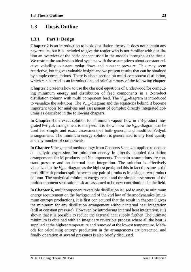
Chapter 2 is an introduction to basic distillation theory. It does not contain anew results, but it is included to give the reader who is not familiar with distiltion an overview of the basic concept used in the models throughout the thWe restrict the analysis to ideal systems with the assumptions about constanative volatility, constant molar flows and constant pressure. This may srestrictive, but it gives valuable insight and we present results that can be obtaby simple computations. There is also a section on multi-component distillatwhich can be read as an introduction and brief summary of the following chap
Chapter 3 presents how to use the classical equations of Underwood for coming minimum energy and distribution of feed components in a 2-proddistillation column with multi component feed. TheVmin-diagram is introducedto visualize the solutions. TheVmin-diagram and the equations behind it becomimportant tools for analysis and assessment of complex directly integratedumns as described in the following chapters.
In Chapter 4 the exact solution for minimum vapour flow in a 3-product integrated Petlyuk arrangement is analysed. It is shown how theVmin-diagram can beused for simple and exact assessment of both general and modified Pearrangements. The minimum energy solution is generalized to any feed quand any number of components.
In Chapter 5 the general methodology from Chapters 3 and 4 is applied to dedan analytic expression for minimum energy in directly coupled distillatiarrangements for M-products and N components. The main assumptions arestant pressure and no internal heat integration. The solution is effectivisualized in theVmin-diagram as the highest peak, and this in fact the same asmost difficult product split between any pair of products in a single two-prodcolumn. The analytical minimum energy result and the simple assessment omulticomponent separation task are assumed to be new contributions in the
In Chapter 6, multicomponent reversible distillation is used to analyse minimuenergy requirement on the background of the 2nd law of thermodynamics (mmum entropy production). It is first conjectured that the result in chapter 5 gthe minimum for any distillation arrangement without internal heat integrat(still at constant pressure). However, by introducing internal heat integration,shown that it is possible to reduce the external heat supply further. The ultimminimum is obtained with an imaginary reversible process where all the hesupplied at the highest temperature and removed at the lowest temperature.ods for calculating entropy production in the arrangements are presentedfinally operation at several pressures is also briefly discussed.
NTNU Dr. ing. Thesis 2001:43 Ivar J. Halvorsen

24
tednt ao theSE/
omieve
ousnite
3-r-t (inuad-eamrityperly.
ith-pt of). ANotee.g.n-ny
les
nt
n jour-tersdif-
laren-n.
1.3.2 Part II: Operation
Chapter 7 would be the starting point of this thesis if the results were presenin chronological order. This chapter is recommended for a reader who waintroduction to the Petlyuk arrangement, its operational characteristics and tconcept of self-optimizing control. The content was first presented at the PESCAPE conference in May 1997. Part I of this thesis, is really a spin-off frmore comprehensive studies of complex integrated columns, in order to achbetter understanding of their operational characteristics.
In Chapter 8 the methods from Chapter 7 are applied to evaluate how varifeed properties affects the characteristics of the Petlyuk column with infinumber of stages and sharp product splits.
Chapter 9 extends the analysis to non-sharp product specifications for theproduct case. TheVmin-diagram from Chapter 4 is particularly useful for this pupose. It is shown that the optimality region is expanded from a line segmenthe plane spanned by two degrees of freedom) for sharp product splits, to a qrangle-shaped region where the width depends mainly on the side-strimpurity. The results also explain why it may be impossible to reach high puin the side-stream in some cases when the degrees of freedom are not set pro
Chapter 10 is the most independent chapter in this thesis, and it can be read wout any knowledge about distillation. Here the focus is on the general conceself-optimizing control, which has been presented by Skogestad et al. (1999method based on Taylor-series expansion of the loss function is presented.that we have not covered other possible approaches for optimizing control,EVOP (Box 1957) or use of on-line optimization. However, self-optimizing cotrol is a tool for control structure design, thus it can be combined with aoptimizing control approach.
Chapter 11 is the result of a simulation study where various candidate variabfor self-optimizing control for the 3-product Petlyuk column were evaluated.
Finally, Chapter 12 makes a summary and conclusion of the most importaresults of the thesis and discusses directions for further work.
Several chapters are self-contained papers, presented at conferences and inals. Thus the reader will find that the introductory parts in several chapcontain some overlapping information, and that the notation may be slightlyferent in the first and second part.
In Appendix A-D some related results are included. We recommend in particuAppendix D, which shows how to use a standard rigorous simulator with convtional column models to find the optimal operating point for a Petlyuk colum
NTNU Dr. ing. Thesis 2001:43 Ivar J. Halvorsen
rgye-ownentlits aresolu-of
anyd theumn
andl
pres-pleder, byvesthepos-the
Chapter 12
Conclusions and Further Work
12.1 Contributions
The main contribution in this work is on the improved understanding of eneconsumption and minimum energy operation in directly (fully thermally) intgrated distillation arrangements (generalized Petlyuk columns). We have shthat the minimum total vapour flow requirement in a multi-product arrangemis given directly by the minimum vapour flow for the most difficult binary spbetween two of the product component groups in the feed mixture. The resultbased on Underwood’s classical equations, and we present exact analyticaltions for ideal mixtures with constant relative volatility and infinite numberstages.
The Vmin-diagram has been introduced as a useful tool for assessment ofmulti-component separation task. The total required energy consumption anvapour load and separation carried out in all parts in a directly integrated colarrangement can be obtained by just a glance at theVmin-diagram. Both the ana-lytical expressions for minimum vapour flow for more than three componentsproducts, and the visualization by theVmin-diagram are believed to be originamaterial.
When we consider integrated distillation arrangements operating at constantsure and without internal heat integration, we conjecture that the directly couextended Petlyuk arrangement has the lowest energy consumption. Howevanalysing the separation task in the view of reversible distillation, which giminimum separation work (zero lost work or entropy production), we find thatexternal requirement for heat supply can be further reduced when we utilizesibilities for internal heat transfer between different column sections inarrangement.
NTNU Dr. ing. Thesis 2001:43 Ivar J. Halvorsen
336
aryoper-ably
Oneoiceea-alityes.timaloteimal
elyd by
ontrols).
e 3-om-) foruta-the
pu-
ign,, andativewere
ea-ing
ries
mustcess
on-the
tegy
We also focus on operation. Although the minimum energy expression for ternPetlyuk arrangements has been known for some time, important aspects ination have not been fully covered in the literature. There have been, and probstill is, reluctance from the industry to use directly coupled arrangements.reason has been given as difficulties in control. This thesis reveals that the chof control strategy is of vital importance for successful operation. The main rson is that the energy consumption increases rapidly outside the optimregion, and the optimality region itself is affected by unknown disturbancThus, we must carefully use the available degrees of freedom to track the opoperation region. Otherwise, the potential saving will most likely be lost. Nalso that a low purity in the sidestream product is also an indicator of suboptoperation.
Thus, the difficulties in control that are reported in the literature are most likdue to bad selection of control structures. Such control problems can be solvechoosing a suitable set of measurements and manipulated inputs, and the citself may be realized by conventional single control loops (e.g. PI-controller
In Chapter 7 we analysed the most important operational characteristics of thproduct Petlyuk column using a finite stage model, and we showed how to cpute the solution surface (vapour flow as function of the degrees of freedominfinite number of stages, outside the region of optimal operation. The comptions for infinite number of stages are based on analytic equations andcomputational load for this limiting case is extremely small compared to comtations on even the simplest finite stage-by-stage models.
The concept of self-optimizing control has been used for control structure desand in particular to propose variables that should be controlled to a setpointat the same time, this ensure close to optimal operation. First we used qualitmethods to propose some good candidates in Chapter 7, and some of theseevaluated in Chapter 11 with a full model. The conclusion is that is not only fsible, but probably also required in practice, to use some kind of self-optimizcontrol in order to maintain close to optimal operation.
A general method for analysis of self-optimizing control based on Taylor-seexpansion of the loss function is given in Chapter 10.
We emphasize that during the design of closely integrated process units wealso focus on control and operation. A common misunderstanding in the prodesign community is to think that controlcomes by itself. Similarly, in the controlcommunity, some think that all problems can be solved with more complex ctrol algorithms. However, the results in this thesis show that by understandingprocess, the control strategy can be quite simple, butwe have to do it right.
It is not enough to compute the optimal operation point. We also need a strato implement and maintain optimal operation in practice.
NTNU Dr. ing. Thesis 2001:43 Ivar J. Halvorsen

12.2 Further Work 337
con-ewreal
and-f the
ssurealso.
sec-ionscanentsight),verynd
s ontion
also
-linecar-ed
ntol-the
isthod-. The
12.2 Further Work
12.2.1 Process Design
The main results presented in this thesis are developed for ideal systems withstant relative volatility and constant molar flows. However, based on the nunderstanding, it is straightforward to develop engineering procedures forzeotropic mixtures. Appendix D contains a simple example of how to use a stard simulator with standard two-product columns to find the characteristics ominimum energy solution for a directly coupled arrangement.
We have assumed constant pressure. However, operation on different prelevels is widely used in process design, and this issue calls for further studiesfor directly integrated columns. This also applies for internal heat integration
There is a large number of different ways to interconnect the internal columntions in directly coupled arrangements. However, the minimum energy solutwill in general be the same, but there will obviously be other features whichbe very important for industrial realizations which makes some arrangemmore suitable than others. Some examples are required physical size (hedesign of the internals, and need for pumps and valves in the connections. Aimportant issue is how to implement control devices for adjusting the liquid avapour splits during the operation.
Another important issue is process integration within a large plant. The resultdirectly coupled columns should be incorporated in the process integratoolboxes.
The extension to azeotropic mixtures and integration of reactive sectionsrequire further studies.
12.2.2 Control Structure Design
We have shown that it is very important to adjust the degrees of freedom onin order to track the minimum energy operating point. However, we have notried out a detailed controllability study where we look at the combinrequirements for composition control and minimum energy operation.
We should also pay attention to the trade-off between column design and colability. For example, one issue is how the number of stages affectscontrollability.
The principle of selfoptimizing control for selection of controlled variablespromising, and the methods can be developed further. This is a general meology and the directly coupled arrangements are just one application area
NTNU Dr. ing. Thesis 2001:43 Ivar J. Halvorsen
338
reatnced
mayndnge-lledes of
proc-ectlyed fortions
ini-e intatewer
ntrolureuence
veer isus
the.
rtantlytice alsoved.sues,
idea is to achieve robust and simple control structures. This issue is of gimportance both when we use simple and conventional controllers or advacontrol with on line optimization.
An important subject for research is how to treat operational constraints. Thisinvolve how to handle situations when it is infeasible to fulfil all constraints, ahow to recover in such conditions. For example, in the 3-product Petlyuk arrament we may relax the purity specification in the sidestream in a contromanner when we are not able to supply sufficient energy or adjust the degrefreedom to the optimal solution.
12.2.3 Advanced Control
Model based predictive control has been applied with success on a series ofess control applications, and we should also consider such methods for dircoupled arrangements. However, the most widespread solutions are designsetpoint control only. The main advantages compared to conventional soluare their ability to handle constraints and multivariable process interactions.
In a directly coupled distillation arrangement we need to operate close to mmum energy. Thus we really need to include a general profit criterion on-linaddition to setpoint deviation criteria. Typical solutions today involve steady soptimization at the highest level, which computes the setpoints for the lolevels.
Note that advanced control methods do not replace the need for good costructure design. Thus selfoptimizing control is well suited for control structdesign also when we consider advanced model based methods. One conseqis that the models required for optimization may become simpler.
12.3 Postscript
In this work, Matlab® has been the main computation tool. In addition I hasometimes used Maple in my search for analytical results, but pen and papstill the most important tool in this context. Hysys models with more rigorothermodynamic properties have been used to verify some of the results fromsimple models based on constant relative volatility and constant molar flows
Simulation studies with simple stage-by-stage models have played an imporole during the work with this thesis. For example, the existence of the anaresults has in several cases first been indicated by simulation studies. We havused simulations to get a practical confirmation of analytic results yet not proHowever, since we have been able to present analytic results on central isthese detailed simulation results have been omitted in the final thesis.
NTNU Dr. ing. Thesis 2001:43 Ivar J. Halvorsen