
Mineral Processing
28
1 | Page Synopsis This report details an investigation made into the Ilmenite Smelting Process. The aim of this practical was the preparation and operation the 60 kW DC plasma-Arc Furnace and to obtain better understanding of the chemistry and thermodynamics of the ilmenite smelting process. This achieved by smelting the ilmenite at 1700°C with anthracite as a reductant in an electric furnace to produce high Titania slag as a major product. In the process, liquid iron and carbon monoxide were produced as by-products. The amount of off-gas and iron evolved is 72.092 g and 104.58 g respectively. The amounts of product formed are dependent on the starting conditions. The intensity of the arc is proportion to the arc length and current.
-
Upload
lungapatso -
Category
Documents
-
view
88 -
download
2
description
smelter
Transcript of Mineral Processing
1 | P a g e
Synopsis
This report details an investigation made into the Ilmenite Smelting Process. The aim
of this practical was the preparation and operation the 60 kW DC plasma-Arc
Furnace and to obtain better understanding of the chemistry and thermodynamics of
the ilmenite smelting process. This achieved by smelting the ilmenite at 1700°C with
anthracite as a reductant in an electric furnace to produce high Titania slag as a
major product. In the process, liquid iron and carbon monoxide were produced as
by-products. The amount of off-gas and iron evolved is 72.092 g and 104.58 g
respectively. The amounts of product formed are dependent on the starting
conditions. The intensity of the arc is proportion to the arc length and current.
2 | P a g e
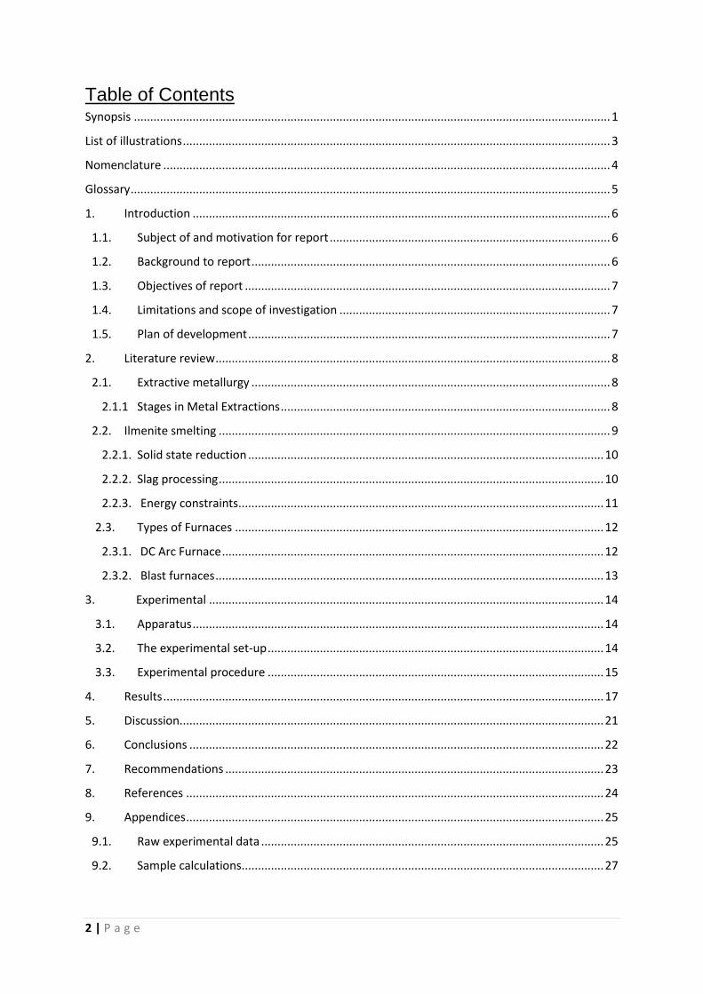
Table of Contents Synopsis .................................................................................................................................................. 1
List of illustrations ................................................................................................................................... 3
Nomenclature ......................................................................................................................................... 4
Glossary ................................................................................................................................................... 5
1. Introduction ................................................................................................................................ 6
1.1. Subject of and motivation for report ...................................................................................... 6
1.2. Background to report .............................................................................................................. 6
1.3. Objectives of report ................................................................................................................ 7
1.4. Limitations and scope of investigation ................................................................................... 7
1.5. Plan of development ............................................................................................................... 7
2. Literature review ......................................................................................................................... 8
2.1. Extractive metallurgy .............................................................................................................. 8
2.1.1 Stages in Metal Extractions ..................................................................................................... 8
2.2. Ilmenite smelting ........................................................................................................................ 9
2.2.1. Solid state reduction ............................................................................................................. 10
2.2.2. Slag processing ...................................................................................................................... 10
2.2.3. Energy constraints ................................................................................................................ 11
2.3. Types of Furnaces ................................................................................................................. 12
2.3.1. DC Arc Furnace ..................................................................................................................... 12
2.3.2. Blast furnaces ....................................................................................................................... 13
3. Experimental ......................................................................................................................... 14
3.1. Apparatus .............................................................................................................................. 14
3.2. The experimental set-up ....................................................................................................... 14
3.3. Experimental procedure ....................................................................................................... 15
4. Results ....................................................................................................................................... 17
5. Discussion .................................................................................................................................. 21
6. Conclusions ............................................................................................................................... 22
7. Recommendations .................................................................................................................... 23
8. References ................................................................................................................................ 24
9. Appendices ................................................................................................................................ 25
9.1. Raw experimental data ......................................................................................................... 25
9.2. Sample calculations............................................................................................................... 27
3 | P a g e
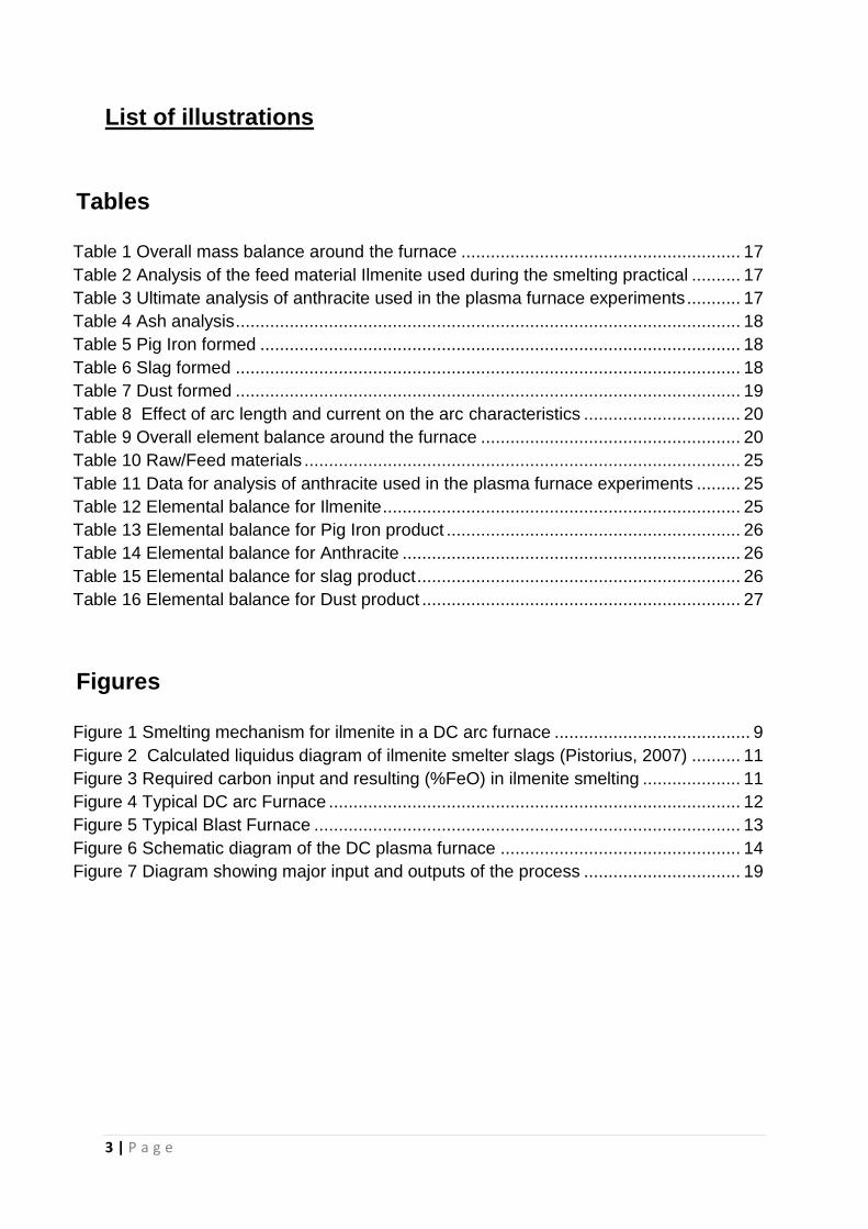
List of illustrations
Tables
Table 1 Overall mass balance around the furnace ......................................................... 17
Table 2 Analysis of the feed material Ilmenite used during the smelting practical .......... 17
Table 3 Ultimate analysis of anthracite used in the plasma furnace experiments ........... 17
Table 4 Ash analysis ....................................................................................................... 18
Table 5 Pig Iron formed .................................................................................................. 18
Table 6 Slag formed ....................................................................................................... 18
Table 7 Dust formed ....................................................................................................... 19
Table 8 Effect of arc length and current on the arc characteristics ................................ 20
Table 9 Overall element balance around the furnace ..................................................... 20
Table 10 Raw/Feed materials ......................................................................................... 25
Table 11 Data for analysis of anthracite used in the plasma furnace experiments ......... 25
Table 12 Elemental balance for Ilmenite ......................................................................... 25
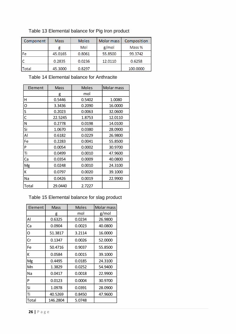
Table 13 Elemental balance for Pig Iron product ............................................................ 26
Table 14 Elemental balance for Anthracite ..................................................................... 26
Table 15 Elemental balance for slag product .................................................................. 26
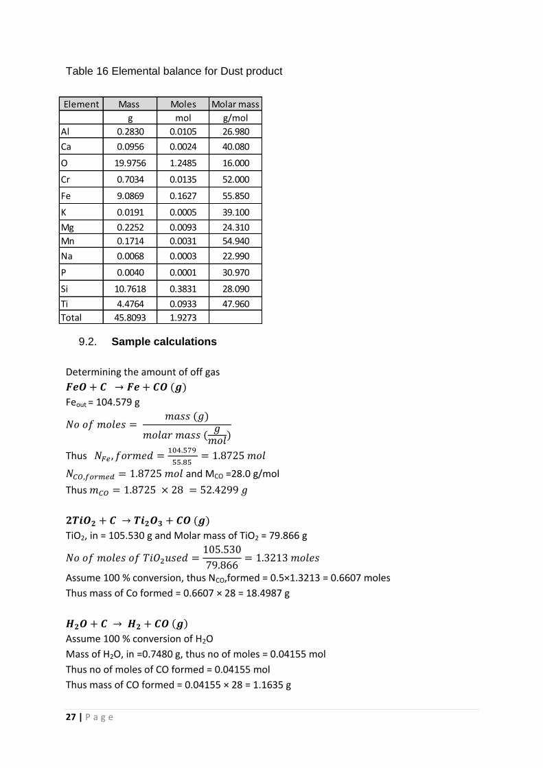
Table 16 Elemental balance for Dust product ................................................................. 27
Figures
Figure 1 Smelting mechanism for ilmenite in a DC arc furnace ........................................ 9
Figure 2 Calculated liquidus diagram of ilmenite smelter slags (Pistorius, 2007) .......... 11
Figure 3 Required carbon input and resulting (%FeO) in ilmenite smelting .................... 11
Figure 4 Typical DC arc Furnace .................................................................................... 12
Figure 5 Typical Blast Furnace ....................................................................................... 13
Figure 6 Schematic diagram of the DC plasma furnace ................................................. 14
Figure 7 Diagram showing major input and outputs of the process ................................ 19
4 | P a g e
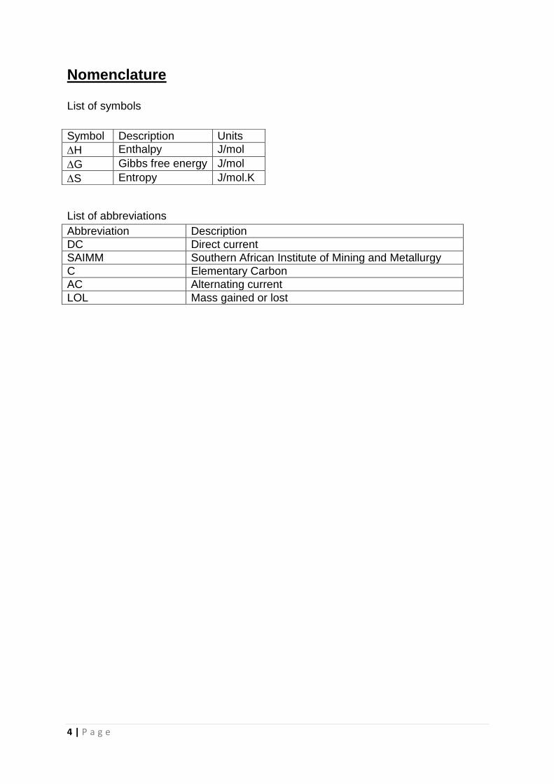
Nomenclature
List of symbols
List of abbreviations
Abbreviation Description
DC Direct current
SAIMM Southern African Institute of Mining and Metallurgy
C Elementary Carbon
AC Alternating current
LOL Mass gained or lost
Symbol Description Units
H Enthalpy J/mol
G Gibbs free energy J/mol
S Entropy J/mol.K
5 | P a g e
Glossary
Ore Is a type of rock that contains minerals with important elements
including minerals.
Metallurgy The science and technology of extracting and refining metals. Pyrometallurgy Involves the extraction of metals through reactions conducted at
high temperatures.
Metamorphic rock Denoting rock that has undergone transformation by heat,
pressure, or other natural agencies.
Igneous rock Formed by the solidification of molten magma.
Arc An electrical conduction through a gas in an applied electric
field.
Furnace An enclosed chamber in which heat is produced to generate
steam, destroy refuse, smelt or refine ores.
Flux In metallurgy, a substance that promotes the fusing of minerals or metals or prevents the formation of oxides
. Mineral A naturally formed chemical element or compound having a
specific chemical composition and, most commonly, a characteristic crystal form.
Reduction A chemical process involving reactions that produce a decrease
in the oxidation state of elements such as iron or sulphur. Slag A glassy waste of the smelting of ores. A mixture of impurities
that separate from reduced metal during smelting. Concentrate The metal-rich product of the beneficiation process that is fed to
the smelter. Beneficiation The processing of ores for the purpose of regulating the size of
a desired product, removing unwanted constituents. Gangue The valueless minerals in an ore; that part of an ore that is
economically desirable but cannot be avoided in mining . Steady state A condition of a physical system or device that does not change
over time.
6 | P a g e
1. Introduction
1.1. Subject of and motivation for report
This report details an investigation made into the Ilmenite Smelting Process. It is
believed that practical preparation and operation of the 60 kW Plama-Arc Furnace
will aid students to attain better understanding of the Ilmenite Smelting Process.
1.2. Background to report
On 22 August 2012 a smelting practical was performed at Stellenbosch, Western
Cape, attended by the directors and the students .Smelting is defined as the
chemical reduction of metal-bearing material such as ore, most commonly by a
process involving fusion, so that lighter and more fusible impurities can be readily
removed (Hudson et al, 1999). The process commonly involves addition of reagents
(fluxes) that facilitate chemical reactions and the separation of metals from
impurities. The process exploits heat and a chemically reducing agent to decompose
the ore, driving off all impurities as gasses or slag and retaining the pure elementary
metal behind. The reducing agent is commonly a source of carbon which removes
oxygen from the ore.
Ilmenite is a commonly accessory mineral found in metamorphic and igneous rocks.
During the 1950’s, ilmenite was mined at Umgubaba as feedstock for a sulphate
pigment plant located at Durban in KwaZulu-Natal In the late 1970’s Richard Bay
Minerals was founded on the east coast of South Africa. On the west coast of South
Africa, Namakwa Sands was founded in the early 1990’s to extract heavy metals
from deposits situated near Vredendal. Dong et al (2012) suggested that ilmenite
supplies about 90% of the world’s demand for titanium minerals and its production
reached 5.8 million metric tons in 2010.
Titanium is the ninth most plentiful element in the earth’s crust and the seventh most
plentiful metallic element (Xue et al, 2012). As a structural metal, titanium is the
fourth largest consumption after aluminium, iron and magnesium. Titanium is the
main raw material in the production of titanium slag, synthetic rutile, titanium dioxide
and spongy titanium. Titanium dioxide is an essential kind of white inorganic
pigment which is largely used in coating, paper, plastics, inks, foods, chemical fibre,
welding rod making, ceramics and metallurgical industries due to its brightness, high
refractive index and whiteness (Kotze, 2007).
7 | P a g e
1.3. Objectives of report
The objectives of this report are therefore:
To obtain a better understanding of the thermodynamics of the ilmenite smelting
process.
To obtain a better understanding of the chemistry of the ilmenite smelting process.
To obtain a better understanding of mineral/phase characterisation and the
appropriate analytical techniques.
1.4. Limitations and scope of investigation
Although there are other types of furnaces available to be utilised in the smelting
process, the focus of this report is limited to the matters that affect the Ilmenite
smelting process operation using a 60 kW DC Plasma-Arc Furnace.
1.5. Plan of development
This report begins with a brief background of the smelting process before describing
the basics of extractive metallurgy. It then focuses on the fundamentals of the
Ilmenite smelting process and experimental methods. Attention is then paid in the
overall mass balance around the furnace. Conclusions are then drawn on the basis
of these results and finally, recommendations are made, based on these
conclusions.
8 | P a g e
2. Literature review
2.1. Extractive metallurgy
Extractive metallurgy is the study of the processes used in the separation and
concentration of raw materials. It deals with extraction and refining of metals. More
than sixty elements are metals which are generally extracted from various forms of
natural occurrence in the earth’s crust (Ray and Ghosh, 1991). Chemical extraction
operations are attained by mixing of the material to be processed with other
chemically active species in a reactor. The reactor may be a furnace, a pressure
vessel or a mixer. Ray and Ghosh (1991) suggested that when ore deposits are
exploited in extractive metallurgy there is generally some waste product. This
product is composed of some minerals in the ore which are not valuable from point
of view of metal extraction and are denoted as gangue minerals.
2.1.1. Stages in Metal Extractions
Rarely can the desired extraction be achieved efficiently in one stage. Metal extract
ions, whether pyrometallurgical or hydrometallurgical in nature, require a series of
processing stages before a high recovery of metal at the required degree of purity
can be attained. The different stages of chemical processing can be group into four
categories as follows:
Preparation or pre-treatment stages.
Extraction stages.
Refining stages.
Metal-recovery stages.
Pyrometallurgy deals with chemical reactions at high temperatures. These reactions
are carried out involves numerous deferent solids, liquids, and gases, and are
carried out using many diverse types of furnaces (Erasmus, 2012).The metals are
extracted by converting sulphides into oxides and then reducing the oxides into
metals, using carbon or carbon monoxide.
Advantages of pyrometallurgical methods (Ray and Ghosh, 1991)
There is a greater ease of physical separation of the product metal from gangue
when the products can be melted or vaporised at high temperatures.
Pyrometallurgical methods of metal production are generally cheaper and
appropriate for large scale production.
Reaction rates are greatly accelerated at high temperatures hence small units
can attain high production rates.
Reactions which are not thermodynamically possible at low temperature become
possible at high temperature.
9 | P a g e
The heat of reaction (H) determines the energy costs of the process (Zietsman,
2004). If the reaction is exothermic, then heat is given off by the reaction, and the
process will be partially self-heating. Contrary, if the reaction is endothermic, the
reaction absorbs heat, which will have to be supplied to the process. Most of the
reactions utilised in Pyrometallurgy are reversible but ilmenite smelting is
characterised by departure from equilibrium in several ways. The Gibbs free energy
(G) of a reaction is a measure of thermodynamic driving force that makes a
reaction to occur (Zietsman, 2004). The entropy change (S) is a measure of the
change in the possibilities for disorder in the products compared to the reactants.
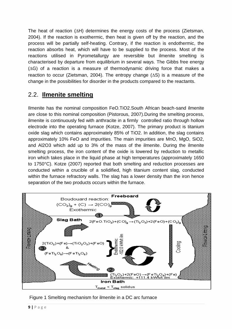
2.2. Ilmenite smelting
Ilmenite has the nominal composition FeO.TiO2.South African beach-sand ilmenite
are close to this nominal composition (Pistorous, 2007).During the smelting process,
ilmenite is continuously fed with anthracite in a firmly controlled ratio through hollow
electrode into the operating furnace (Kotze, 2007). The primary product is titanium
oxide slag which contains approximately 85% of TiO2. In addition, the slag contains
approximately 10% FeO and impurities. The main impurities are MnO, MgO, SiO2,
and Al2O3 which add up to 3% of the mass of the ilmenite. During the ilmenite
smelting process, the iron content of the oxide is lowered by reduction to metallic
iron which takes place in the liquid phase at high temperatures (approximately 1650
to 1750°C). Kotze (2007) reported that both smelting and reduction processes are
conducted within a crucible of a solidified, high titanium content slag, conducted
within the furnace refractory walls. The slag has a lower density than the iron hence
separation of the two products occurs within the furnace.
Figure 1 Smelting mechanism for ilmenite in a DC arc furnace
10 | P a g e
2.2.1. Solid state reduction
When the electric furnace operates, the electric arc generates at the bottom of the
electrode (Xue, et al, 2012). The temperature of the materials then rises due to the
heat from electric arc and electrode. When the temperature is high enough, ilmenite
reacts with carbon (reductant) and the main reactions are the following:
Reduction of FeO from the slag:
[1]
Partial reduction of TiO2 in the slag:
[2]
The main reaction in the furnace can be summarised as:
( ) ( ) ( ) [3]
Thermodynamically, the major gas product is CO when the system temperature is
lower or higher than the boudouard temperature. The CO gas produced by the
furnace passes through the gas-cleaning plants, where the gas is cooled, scrubbed,
and washed, to remove entrained dust from the furnace (Gous, 2006). The gas can
then be directed to the gas-holder for use in pre-heating of ilmenite and the drying of
anthracite. Gous (2006) further suggested that a portion of the ilmenite feed can be
pre-heated in the pre-heaters, thus lowering the specific energy requirement of the
process.
2.2.2. Slag processing
Xue et al (2012) reported that particles begin to melt when the temperature rises up
to the melting point of the titanium slag, metallic iron or the unreacted ilmenite. The
slag is made up of unreacted ilmenite, titanium oxides and other impurity oxides.
When the melting process has completed, the reduction of iron oxides from
unreduced ilmenite depends on the reaction with solid carbon reductant particle that
is suspended in the melt and CO bubble in the melt. Since the slag is less dense
than iron, the slag floats on iron inside the furnace.
Dong et al (2012) suggested that when the reduction process is complete, the
electrodes are typically lifted for rising system temperature in order to improve fluidity
and the separation of slag-iron. Slag and iron are then cooled naturally after being
discharged from the furnace.
The solidified slag is a largely single-phase (pseudobrookite-M3O5-phase), with only
small proportions of other phases, mainly rutile and silicates (Pistorous 2007).The
reactions are carried out at high temperatures since the melting point of the high-
titania slag is around 1650°C.
11 | P a g e
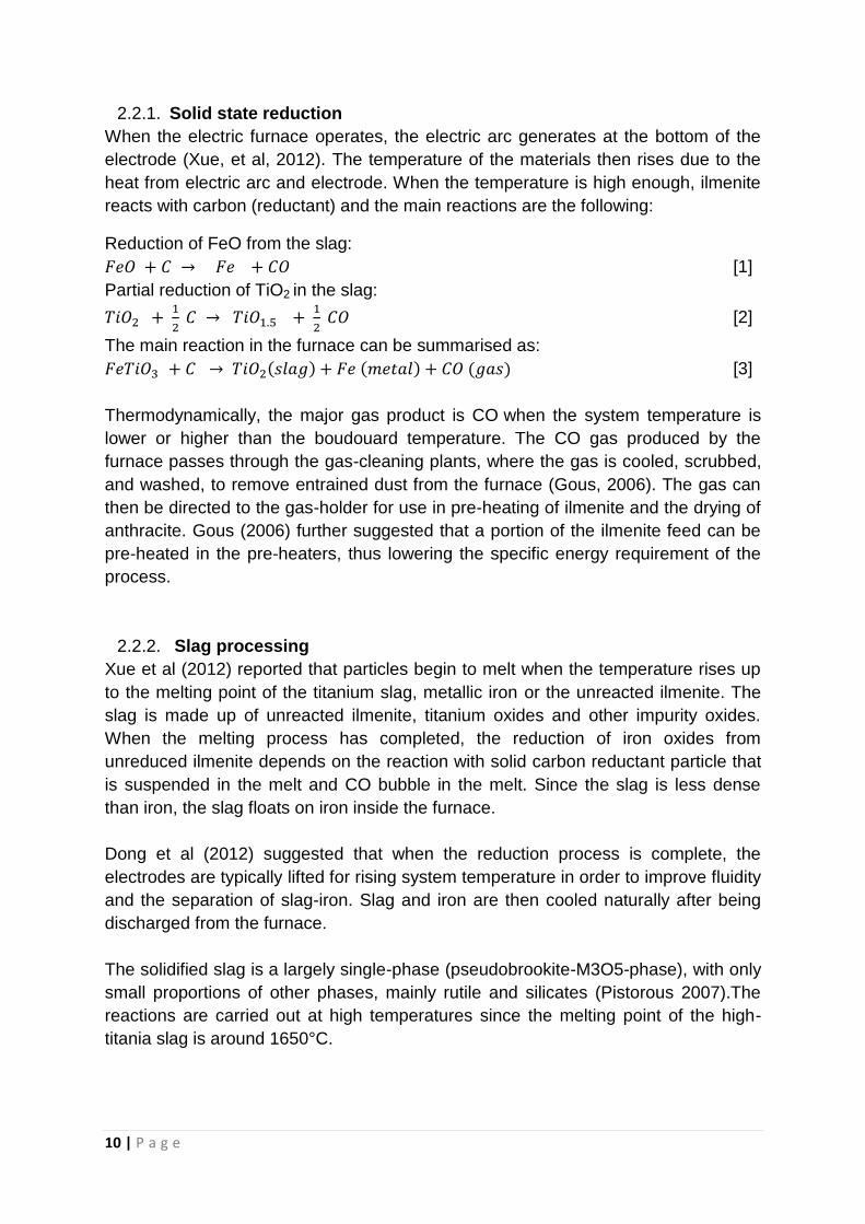
Figure 2 Calculated liquidus diagram of ilmenite smelter slags (Pistorius, 2007)
Pistorous (2007) suggested that Figure illustrates that both FeO and TiO1.5 serve to
flux TiO2, thus lowering the liquidus temperature of the slag.
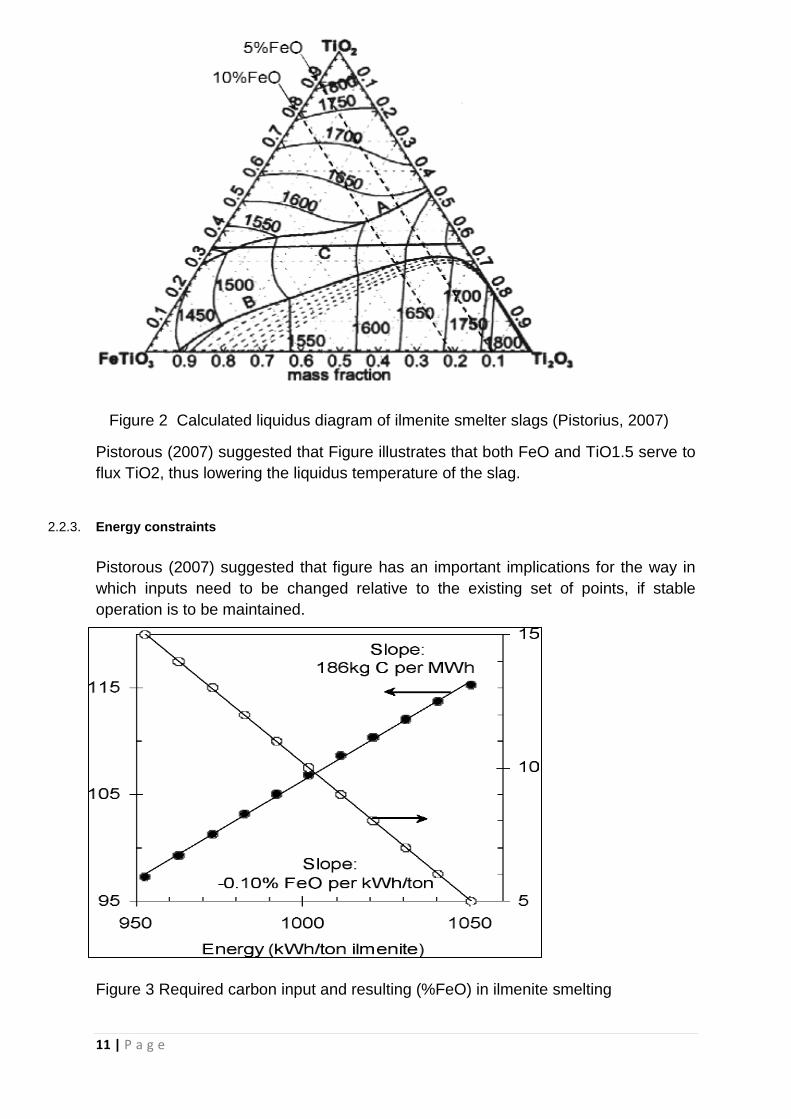
2.2.3. Energy constraints
Pistorous (2007) suggested that figure has an important implications for the way in
which inputs need to be changed relative to the existing set of points, if stable
operation is to be maintained.
Figure 3 Required carbon input and resulting (%FeO) in ilmenite smelting
12 | P a g e
It is approximated that 5.3 kWh increased in electrical energy input, the carbon input
needs to be increased by 1 kg. The published enthalpy correlations show that
heating 1 ton of pure ilmenite and 100 kg of carbon to 1600 °C requires some 640
kWh per ton of ilmenite (Pistorius, 2007).
2.3. Types of Furnaces
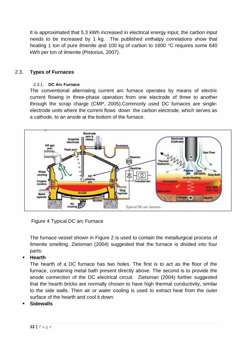
2.3.1. DC Arc Furnace
The conventional alternating current arc furnace operates by means of electric
current flowing in three-phase operation from one electrode of three to another
through the scrap charge (CMP, 2005).Commonly used DC furnaces are single-
electrode units where the current flows down the carbon electrode, which serves as
a cathode, to an anode at the bottom of the furnace.
Figure 4 Typical DC arc Furnace
The furnace vessel shown in Figure 2 is used to contain the metallurgical process of
ilmenite smelting. Zietsman (2004) suggested that the furnace is divided into four
parts:
Hearth
The hearth of a DC furnace has two holes. The first is to act as the floor of the
furnace, containing metal bath present directly above. The second is to provide the
anode connection of the DC electrical circuit. Zietsman (2004) further suggested
that the hearth bricks are normally chosen to have high thermal conductivity, similar
to the side walls. Then air or water cooling is used to extract heat from the outer
surface of the hearth and cool it down.
Sidewalls
13 | P a g e
The sidewalls of an ilmenite-smelting furnace must extract heat from the slag bath at
a high adequate rate to establish and maintain a freeze lining of the solidified slag on
the wall.
Roof
The roof of the furnace acts as a lid, closing the furnace so that no gas, fames or
dust escapes other than through the off-gas duct.
Tap holes
The tap holes are installed into the furnace sidewalls. They assemblies usually
include water cooling intended at preventing overheating and excessive wear of
refractory lining in the region of tap holes.
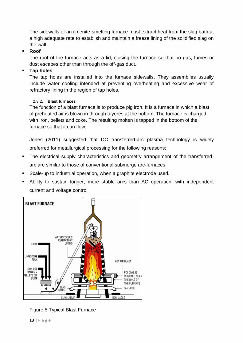
2.3.2. Blast furnaces
The function of a blast furnace is to produce pig iron. It is a furnace in which a blast
of preheated air is blown in through tuyeres at the bottom. The furnace is charged
with iron, pellets and coke. The resulting molten is tapped in the bottom of the
furnace so that it can flow.
Jones (2011) suggested that DC transferred-arc plasma technology is widely
preferred for metallurgical processing for the following reasons:
The electrical supply characteristics and geometry arrangement of the transferred-
arc are similar to those of conventional submerge arc-furnaces.
Scale-up to industrial operation, when a graphite electrode used.
Ability to sustain longer, more stable arcs than AC operation, with independent
current and voltage control
Figure 5 Typical Blast Furnace
14 | P a g e
3. Experimental
3.1. Apparatus
60 kW DC Plasma-ARC Furnace
Ilmenite (TiO2Fe2O3)
Anthracite
Optical Pyrometer
Iron cubes
Weighing scale
Alumina bubble
Fiber-Frax (ceramic blanket insulator)
Sample containers
Hammer and chisel/diamond saw
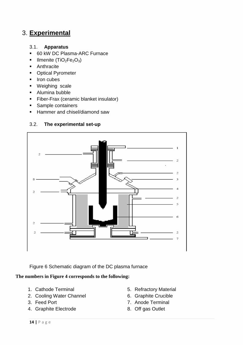
3.2. The experimental set-up
Figure 6 Schematic diagram of the DC plasma furnace
The numbers in Figure 4 corresponds to the following:
1. Cathode Terminal
2. Cooling Water Channel
3. Feed Port
4. Graphite Electrode
5. Refractory Material
6. Graphite Crucible
7. Anode Terminal
8. Off gas Outlet
15 | P a g e
3.3. Experimental procedure
Feed preparation
A mixture of ilmenite and anthracite was prepared for each furnace run. The
reductant (anthracite) was added in a ratio of 127 kg per ton of ilmenite to ensure a
carbon excess for maximum reduction. The total mass of ilmenite added was 241.60
g and the total mass of anthracite was 30.52 g.
Before commencing
The required amounts of anthracite and ilmenite were determined and mixed
together in a container. The alumina “fibrefrax” thermal insulation lining was
prepared for inside of the furnace to protect inner walls and to act as insulation. The
power supply was then turned off at the mains and the cooling water bypass valve
was opened (handle turned parallel to the pipe). The argon gas inlet pipes from sight
ports were removed on the roof of the furnace and the electrode was turned up so
that the tip of the electrode was above the bottom plane of the roof. The off gas
system was then removed from the main furnace body and cleared away from the
furnace. The stand was placed close to the furnace.
Operating procedure
The roof of the furnace was then removed and placed on the stand. It was checked
that the roof was not resting on any water pipes or electric cables before the alumina
insulation fiber was inserted into the furnace. It was ensured that there were no gabs
where the two ends off the fiber meet. Compressed air was then used to clean the
inside of the furnace, ensuring that there were no particles in the notch in the bottom
cathode. The bottom of the crucible was inserted into the notch of the bottom
cathode and checked to see that the crucible was securely in place.
A small amount of the ilmenite and anthracite was then placed into the bottom of the
crucible and positioned in the centre of the crucible to act as a starter to strike an
arc. The sight ports were removed from the furnace roof by removing the screws.
The roof was then placed back on the furnace and ensured that it was secured. The
off gas pipe was then aligned with off gas port on the roof of the furnace. The argon
gas supply was connected to the sight ports and turned on to begin flushing of the
furnace with argon gas. The cooling water bypass valve was then closed to allow the
water to the furnace and all the valves were switched to open positions (parallel to
the pipe). The extractor fan was turned on and it was ensured that the off gas outlet
was free of blockages and that the end of the pipe was securely fixed in the
excavator suction.
16 | P a g e
Smelting
The feeding funnel was inserted in one of the open sight ports and the discharge end
of the vibrating feeder was then placed directly above it. It was insured that the end
of the funnel was able to discharge into the centre of the crucible. Before switching
on the power sources at the mains, it was ensured that the main power supply is off,
by turning the power knob to the left. The main power supply source was turned on
at the mains by flicking both switches upward and initial voltage 20V selected at a
height of 1950 mm. The main power supply was then turned on by turning the power
knob clockwise.
The electrode was then turned down the furnace until it was about 5 cm above the
bottom of the crucible. The electrode was carefully lowered further until the ark was
struck. Once the ark was struck, the crucible was allowed to heat up for two minutes
before feeding was started. After feeding was completed, the voltage and the
electrode position were set to 17V and 1980 mm respectively and left to allow mixing
to take place.
17 | P a g e
Component Mass Moles
g mol Mass %
H2O 0.748 0.042 2.450
Ash 4.157 13.620
S 0.198 0.006 0.650
C 22.524 1.875 73.800
H 0.922 0.457 3.020
N 0.555 0.020 1.820
O 1.416 0.044 4.640
Total 30.520 2.444 100.000
Composition
Component Mass Moles Composition
g mol Mass %
Al2O3 0.918 0.009 0.380
CaO 0.145 0.003 0.060
Cr2O3 0.121 0.001 0.050
Fe2O3 118.697 0.743 49.130
K2O 0.169 0.002 0.070
MgO 1.208 0.030 0.500
MnO 2.609 0.037 1.080
Na2O 0.459 0.007 0.190
P2O5 0.072 0.001 0.030
SiO2 1.860 0.031 0.770
TiO2 105.530 1.321 43.680
LOL -7.538 -3.120
Total 224.251 2.184 92.820
Material Mass Fraction Material Mass Fraction
g Mass g Mass
Ilmenite 241.598 0.746 Slag 140.600 0.434
Antracite 30.520 0.094 Iron phase 45.300 0.140
Iron cubes 51.865 0.160 Dust 46.100 0.142
Unreacted material 17.800 0.055
Off gas 72.092 0.229
Total 323.984 1.000 321.892 1.000
IN OUT
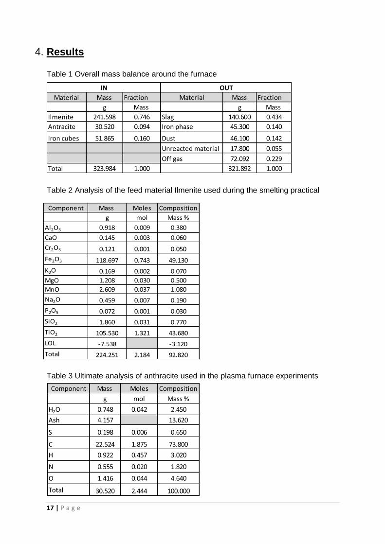
4. Results
Table 1 Overall mass balance around the furnace
Table 2 Analysis of the feed material Ilmenite used during the smelting practical
Table 3 Ultimate analysis of anthracite used in the plasma furnace experiments
18 | P a g e
Component Mass Moles
g Mol Mass %
Fe 45.02 0.81 99.37
C 0.28 0.02 0.63
Total 45.30 0.83 100.00
Composition
Component Mass Moles
g Mol Mass %
Al2O3 1.195 0.012 0.850
CaO 0.127 0.002 0.090
Cr2O3 0.197 0.001 0.140
Fe2O3 72.156 0.452 51.320
K2O 0.070 0.001 0.050
MgO 0.745 0.018 0.530
MnO 1.786 0.025 1.270
Na2O 0.056 0.001 0.040
P2O5 0.028 0.000 0.020
SiO2 2.348 0.039 1.670
TiO2 67.488 0.845 48.000
LOL -6.186 -4.400
Total 140.01 1.40 99.58
Composition
Component Mass Moles
g mol Mass %
SiO2 2.282 0.038 54.900
Al2O3 1.168 0.011 28.100
Fe2O3 0.326 0.002 7.850
P2O5 0.012 0.000 0.300
TiO2 0.083 0.001 2.000
CaO 0.049 0.001 1.190
MgO 0.041 0.001 0.990
K2O 0.096 0.001 2.310
Na2O 0.057 0.001 1.380
SO3 0.010 0.000 0.240
Total 4.126 0.057 99.260
Composition
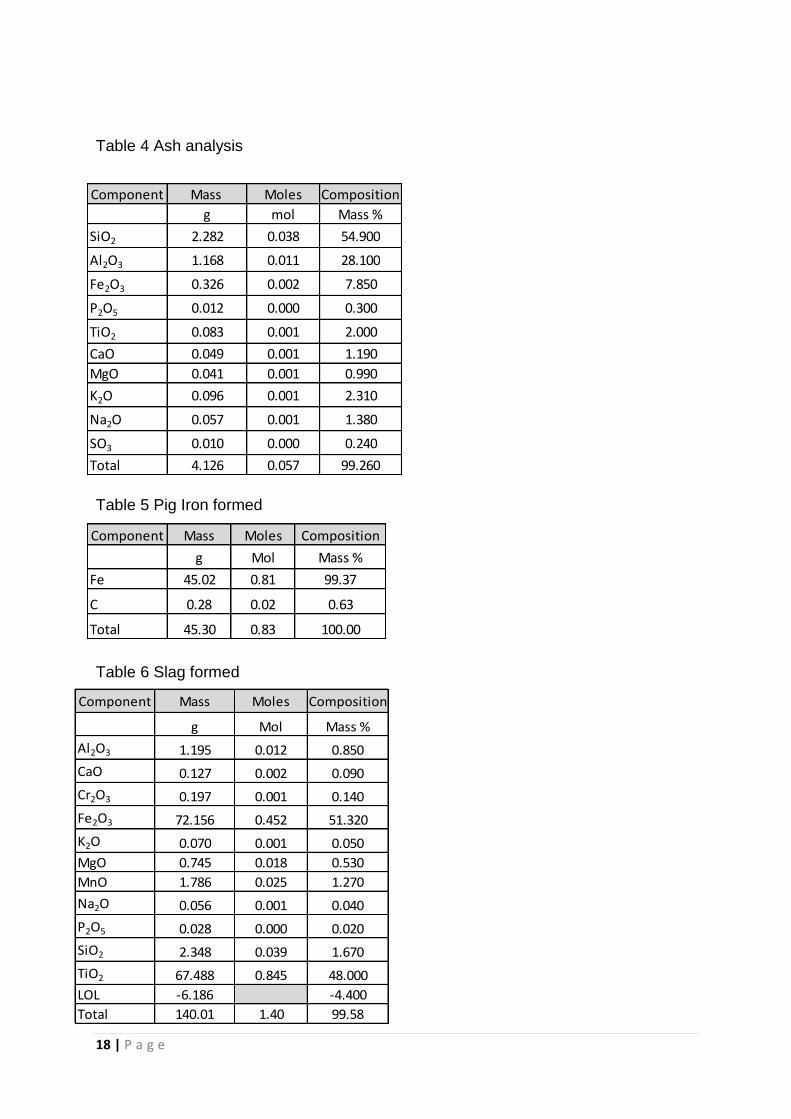
Table 4 Ash analysis
Table 5 Pig Iron formed
Table 6 Slag formed
19 | P a g e
Component Mass Moles
g Mol Mass %
Al2O3 0.535 0.005 1.160
CaO 0.134 0.002 0.290
Cr2O3 1.028 0.007 2.230
Fe2O3 12.991 0.081 28.180
K2O 0.023 0.000 0.050
MgO 0.373 0.009 0.810
MnO 0.221 0.003 0.480
Na2O 0.009 0.000 0.020
P2O5 0.009 0.000 0.020
SiO2 23.018 0.383 49.930
TiO2 7.454 0.093 16.170
LOL 2.125 4.610
Total 47.921 0.585 103.950
Composition
Titania rich slag
Ilmenite
Pig Iron
Dust
Antracite
Off gas
Iron tubes
Unreacted material
Furnace
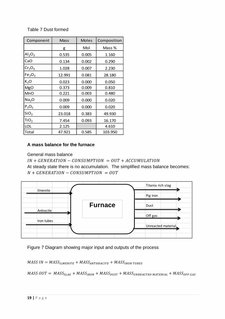
Table 7 Dust formed
A mass balance for the furnace
General mass balance
At steady state there is no accumulation. The simplified mass balance becomes:
Figure 7 Diagram showing major input and outputs of the process
20 | P a g e
Difference
Element Mass Moles Mass Moles
g mol g mol g
Al 1.104 0.041 0.915 0.034 0.189
Ca 0.139 0.003 0.186 0.005 -0.047
O 84.063 5.254 71.357 4.460 12.706
Cr 0.083 0.002 0.838 0.016 -0.755
Fe 135.120 2.419 104.579 1.872 30.541
K 0.220 0.006 0.077 0.002 0.143
Mg 0.753 0.031 0.675 0.028 0.079
Mn 2.021 0.037 1.554 0.028 0.467
Na 0.383 0.017 0.049 0.002 0.335
P 0.037 0.001 0.016 0.001 0.021
Si 1.937 0.069 11.860 0.422 -9.923
Ti 63.421 0.032 45.003 0.938 18.418
H 0.545 0.540 0.000 0.000 0.545
S 0.202 0.006 0.000 0.000 0.202
C 22.524 1.875 0.283 0.024 22.241
N 0.278 0.020 0.000 0.000 0.278
Total 312.831 10.353 237.394 7.832 75.437
IN OUT
Arc length Voltage Current Resistance
mm V A W
1950.00 20.00 2.00 10.00
1980.00 17.00 1.70 10.00
1990.00 19.00 1.90 10.00
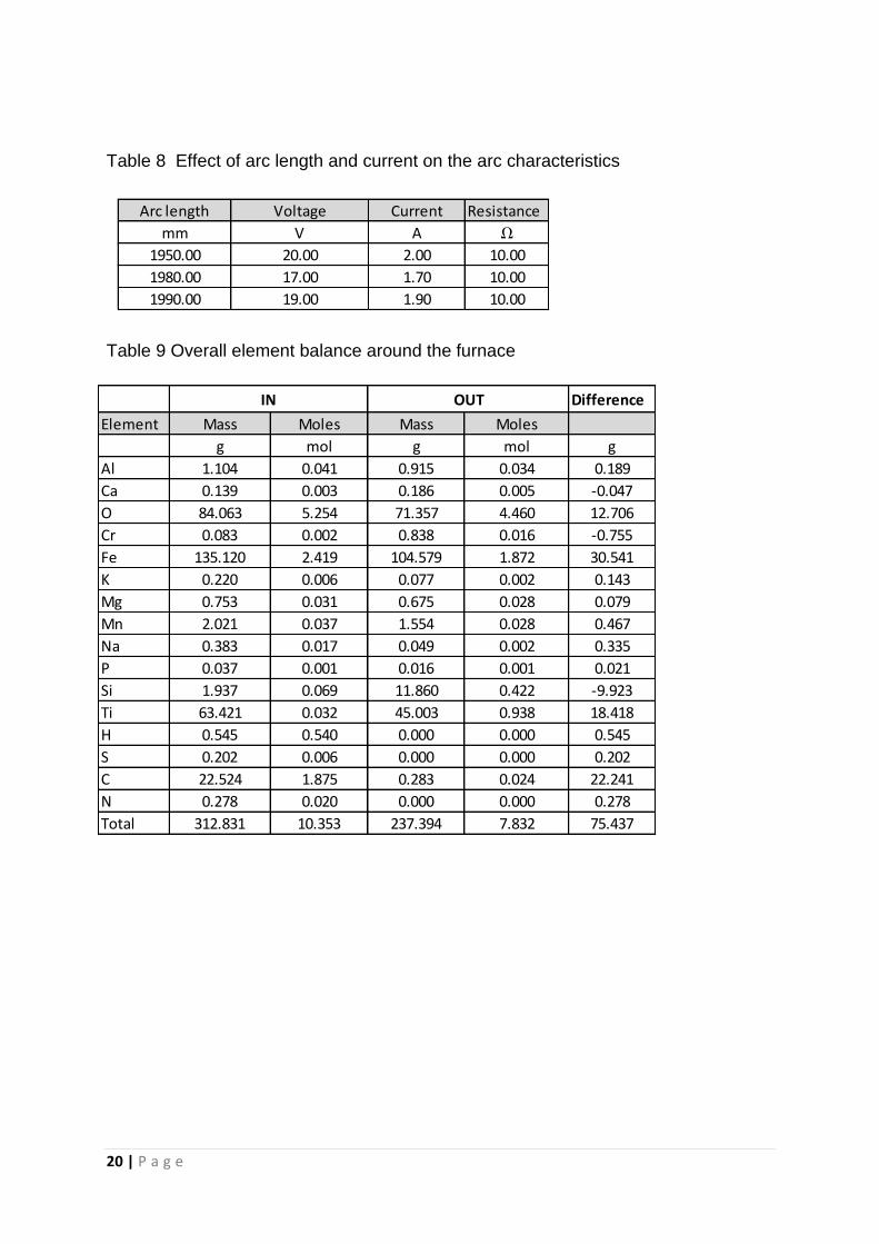
Table 8 Effect of arc length and current on the arc characteristics
Table 9 Overall element balance around the furnace
21 | P a g e
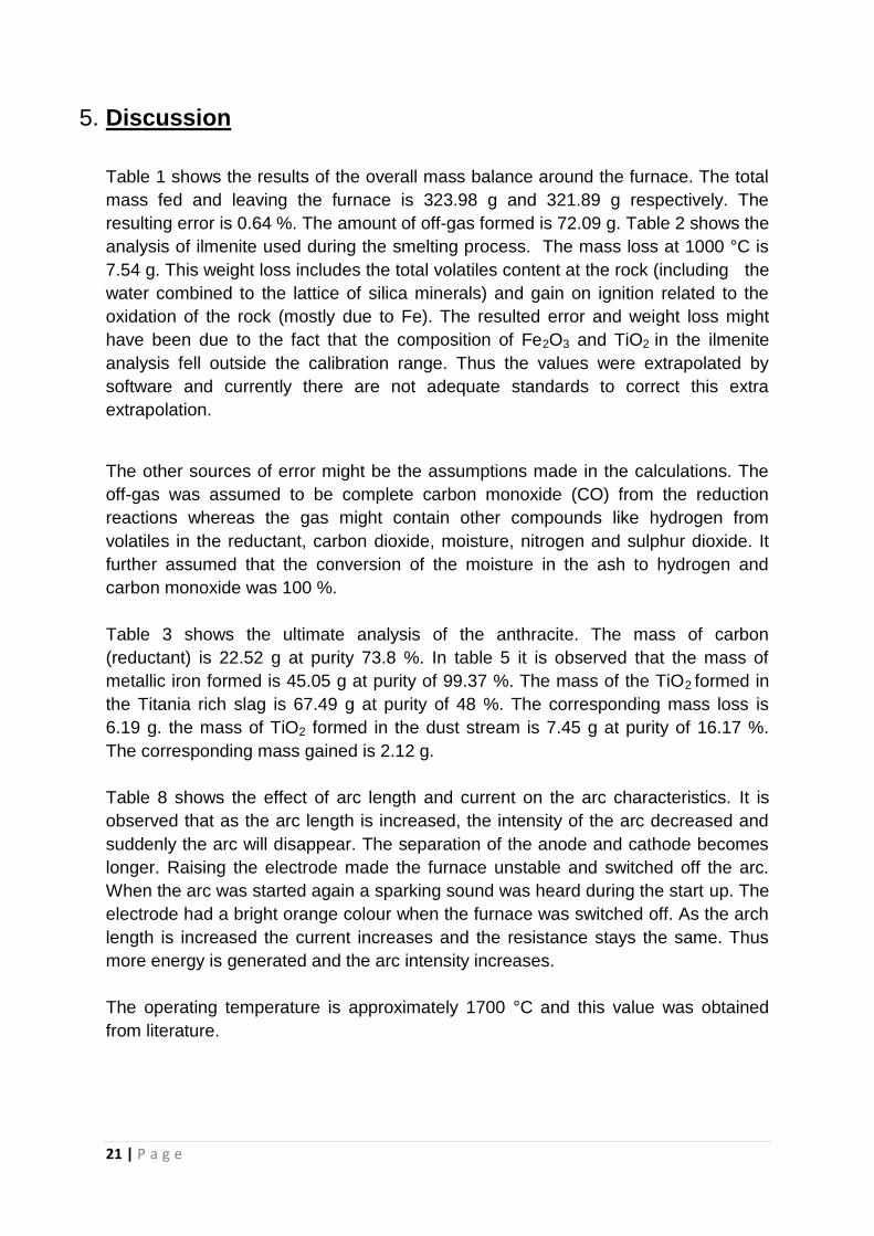
5. Discussion
Table 1 shows the results of the overall mass balance around the furnace. The total
mass fed and leaving the furnace is 323.98 g and 321.89 g respectively. The
resulting error is 0.64 %. The amount of off-gas formed is 72.09 g. Table 2 shows the
analysis of ilmenite used during the smelting process. The mass loss at 1000 °C is
7.54 g. This weight loss includes the total volatiles content at the rock (including the
water combined to the lattice of silica minerals) and gain on ignition related to the
oxidation of the rock (mostly due to Fe). The resulted error and weight loss might
have been due to the fact that the composition of Fe2O3 and TiO2 in the ilmenite
analysis fell outside the calibration range. Thus the values were extrapolated by
software and currently there are not adequate standards to correct this extra
extrapolation.
The other sources of error might be the assumptions made in the calculations. The
off-gas was assumed to be complete carbon monoxide (CO) from the reduction
reactions whereas the gas might contain other compounds like hydrogen from
volatiles in the reductant, carbon dioxide, moisture, nitrogen and sulphur dioxide. It
further assumed that the conversion of the moisture in the ash to hydrogen and
carbon monoxide was 100 %.
Table 3 shows the ultimate analysis of the anthracite. The mass of carbon
(reductant) is 22.52 g at purity 73.8 %. In table 5 it is observed that the mass of
metallic iron formed is 45.05 g at purity of 99.37 %. The mass of the TiO2 formed in
the Titania rich slag is 67.49 g at purity of 48 %. The corresponding mass loss is
6.19 g. the mass of TiO2 formed in the dust stream is 7.45 g at purity of 16.17 %.
The corresponding mass gained is 2.12 g.
Table 8 shows the effect of arc length and current on the arc characteristics. It is
observed that as the arc length is increased, the intensity of the arc decreased and
suddenly the arc will disappear. The separation of the anode and cathode becomes
longer. Raising the electrode made the furnace unstable and switched off the arc.
When the arc was started again a sparking sound was heard during the start up. The
electrode had a bright orange colour when the furnace was switched off. As the arch
length is increased the current increases and the resistance stays the same. Thus
more energy is generated and the arc intensity increases.
The operating temperature is approximately 1700 °C and this value was obtained
from literature.
22 | P a g e
6. Conclusions
Based on the forgoing information, the following conclusions have been made:
The amounts of product formed during the ilmenite smelting process are dependent
on the initial conditions namely the mass of ilmenite, anthracite and the iron cubes.
The arc intensity is directly proportional to the arc length.
The current affects the amount of energy evolved hence the intensity of the arc
formed.
The operating temperature of the furnace lies somewhere between 1600-1700 °C.

23 | P a g e
7. Recommendations
On the basis of the above conclusions, the following recommendations are made:
Find alternative software that will accurately predict the compositions of the
compounds reduce chances of weight loss.
The experiment should be repeated several times for error analysis.
Find an alternative device to measure the temperature during the smelting
process.
24 | P a g e
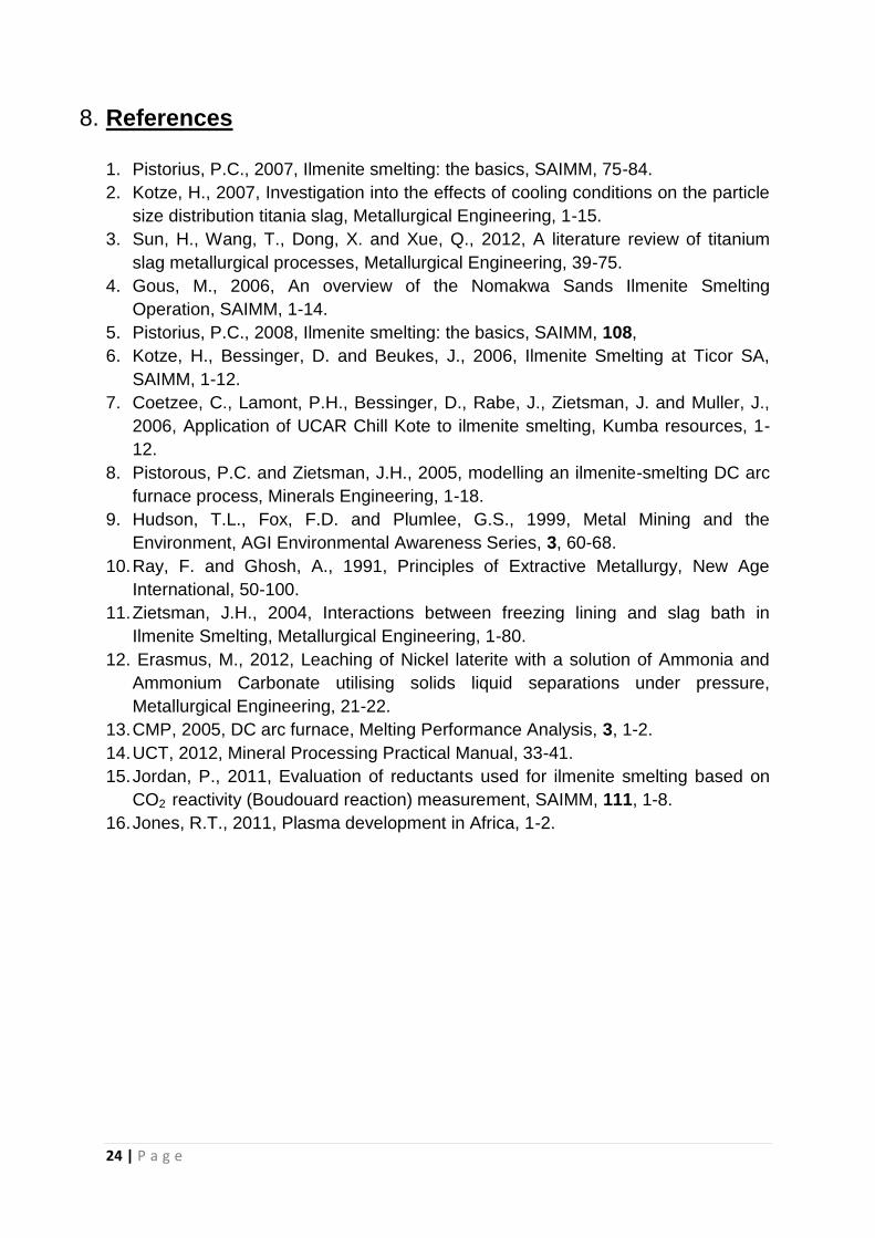
8. References
1. Pistorius, P.C., 2007, Ilmenite smelting: the basics, SAIMM, 75-84.
2. Kotze, H., 2007, Investigation into the effects of cooling conditions on the particle
size distribution titania slag, Metallurgical Engineering, 1-15.
3. Sun, H., Wang, T., Dong, X. and Xue, Q., 2012, A literature review of titanium
slag metallurgical processes, Metallurgical Engineering, 39-75.
4. Gous, M., 2006, An overview of the Nomakwa Sands Ilmenite Smelting
Operation, SAIMM, 1-14.
5. Pistorius, P.C., 2008, Ilmenite smelting: the basics, SAIMM, 108,
6. Kotze, H., Bessinger, D. and Beukes, J., 2006, Ilmenite Smelting at Ticor SA,
SAIMM, 1-12.
7. Coetzee, C., Lamont, P.H., Bessinger, D., Rabe, J., Zietsman, J. and Muller, J.,
2006, Application of UCAR Chill Kote to ilmenite smelting, Kumba resources, 1-
12.
8. Pistorous, P.C. and Zietsman, J.H., 2005, modelling an ilmenite-smelting DC arc
furnace process, Minerals Engineering, 1-18.
9. Hudson, T.L., Fox, F.D. and Plumlee, G.S., 1999, Metal Mining and the
Environment, AGI Environmental Awareness Series, 3, 60-68.
10. Ray, F. and Ghosh, A., 1991, Principles of Extractive Metallurgy, New Age
International, 50-100.
11. Zietsman, J.H., 2004, Interactions between freezing lining and slag bath in
Ilmenite Smelting, Metallurgical Engineering, 1-80.
12. Erasmus, M., 2012, Leaching of Nickel laterite with a solution of Ammonia and
Ammonium Carbonate utilising solids liquid separations under pressure,
Metallurgical Engineering, 21-22.
13. CMP, 2005, DC arc furnace, Melting Performance Analysis, 3, 1-2.
14. UCT, 2012, Mineral Processing Practical Manual, 33-41.
15. Jordan, P., 2011, Evaluation of reductants used for ilmenite smelting based on
CO2 reactivity (Boudouard reaction) measurement, SAIMM, 111, 1-8.
16. Jones, R.T., 2011, Plasma development in Africa, 1-2.
25 | P a g e
Proximate analysis % Ultimate analysis %
Moisture 2.45 Moisture 2.45
Ash 13.62 Ash 13.62
Volatile Combustible Matter 8.46 Sulphur 0.65
Fixed Carbon 74.47 Carbon 73.8
Hydrogen 3.02
Nitrogen 1.82
Oxygen 4.64
Total 99 100
Element Mass Moles Molar mass
g mol g/mol
Al 0.4859 0.0180 26.9800
Ca 0.1036 0.0026 40.0800
O 80.7197 5.0450 16.0000
Cr 0.0827 0.0016 52.0000
Fe 83.0262 1.4866 55.8500
K 0.1404 0.0036 39.1000
Mg 0.7286 0.0300 24.3100
Mn 2.0208 0.0368 54.9400
Na 0.3405 0.0148 22.9900
P 0.0316 0.0010 30.9700
Si 0.8698 0.0310 28.0900
Ti 63.3713 1.3213 47.9600
Total 231.9212 7.9922
Material Mass Fraction
g Mass
Ilmenite 241.598 0.746
Antracite 30.520 0.094
Iron cubes 51.865 0.160
Total 323.984 1.000
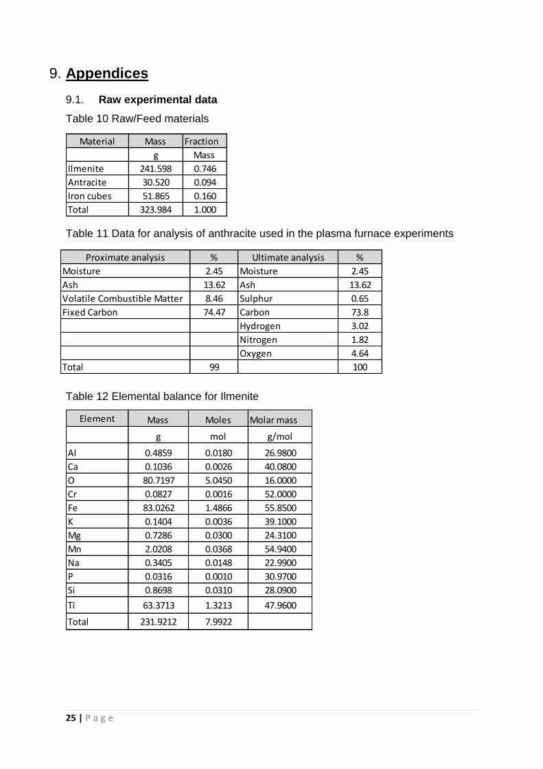
9. Appendices
9.1. Raw experimental data
Table 10 Raw/Feed materials
Table 11 Data for analysis of anthracite used in the plasma furnace experiments
Table 12 Elemental balance for Ilmenite
26 | P a g e
Element Mass Moles Molar mass
g mol
H 0.5446 0.5402 1.0080
O 3.3436 0.2090 16.0000
S 0.2023 0.0063 32.0600
C 22.5245 1.8753 12.0110
N 0.2778 0.0198 14.0100
Si 1.0670 0.0380 28.0900
Al 0.6182 0.0229 26.9800
Fe 0.2283 0.0041 55.8500
P 0.0054 0.0002 30.9700
Ti 0.0499 0.0010 47.9600
Ca 0.0354 0.0009 40.0800
Mg 0.0248 0.0010 24.3100
K 0.0797 0.0020 39.1000
Na 0.0426 0.0019 22.9900
Total 29.0440 2.7227
Element Mass Moles Molar mass
g mol g/mol
Al 0.6325 0.0234 26.9800
Ca 0.0904 0.0023 40.0800
O 51.3817 3.2114 16.0000
Cr 0.1347 0.0026 52.0000
Fe 50.4716 0.9037 55.8500
K 0.0584 0.0015 39.1000
Mg 0.4495 0.0185 24.3100
Mn 1.3829 0.0252 54.9400
Na 0.0417 0.0018 22.9900
P 0.0123 0.0004 30.9700
Si 1.0978 0.0391 28.0900
Ti 40.5269 0.8450 47.9600
Total 146.2804 5.0748
Table 13 Elemental balance for Pig Iron product
Table 14 Elemental balance for Anthracite
Table 15 Elemental balance for slag product
27 | P a g e
Element Mass Moles Molar mass
g mol g/mol
Al 0.2830 0.0105 26.980
Ca 0.0956 0.0024 40.080
O 19.9756 1.2485 16.000
Cr 0.7034 0.0135 52.000
Fe 9.0869 0.1627 55.850
K 0.0191 0.0005 39.100
Mg 0.2252 0.0093 24.310
Mn 0.1714 0.0031 54.940
Na 0.0068 0.0003 22.990
P 0.0040 0.0001 30.970
Si 10.7618 0.3831 28.090
Ti 4.4764 0.0933 47.960
Total 45.8093 1.9273
Table 16 Elemental balance for Dust product
9.2. Sample calculations
Determining the amount of off gas
( )
Feout = 104.579 g
( )
(
)
Thus
and MCO =28.0 g/mol
Thus
( )
TiO2, in = 105.530 g and Molar mass of TiO2 = 79.866 g
Assume 100 % conversion, thus NCO,formed = 0.5×1.3213 = 0.6607 moles
Thus mass of Co formed = 0.6607 × 28 = 18.4987 g
( )
Assume 100 % conversion of H2O
Mass of H2O, in =0.7480 g, thus no of moles = 0.04155 mol
Thus no of moles of CO formed = 0.04155 mol
Thus mass of CO formed = 0.04155 × 28 = 1.1635 g

28 | P a g e
Hence total mass of CO formed = 52.4299 + 18.4987 + 1.1635 = 72.0921 g
2.