MASONEILAN - Manual de Operacion, Mantenimiento y Lista de Partes.pdf
43
-
Upload
jose-maria-rodriguez-rivera -
Category
Documents
-
view
88 -
download
2
description
Manual de operación y mantenimiento de válvulas
Transcript of MASONEILAN - Manual de Operacion, Mantenimiento y Lista de Partes.pdf


Masoneilan®
39003 SeriesHigh PerformanceButterfly Valves (HPBV)
Instructions
EM9003
9/00

EM9003 9/0039003 Series2
1. Introduction1.1 Valve Description .................................................................................................... 31.2 Valve Design Features ........................................................................................... 31.3 Flange Compatibility ............................................................................................... 31.4 Gasket Compatibility ............................................................................................... 31.5 Pipe Schedule Compatibility ................................................................................... 31.6 Numbering System ................................................................................................. 41.7 Operating Pressures ............................................................................................... 61.8 Seat Alternatives..................................................................................................... 61.9 Offset Disc Design .................................................................................................. 61.10 Seat Retainer Alternatives ...................................................................................... 7
2. Installation Recommendations2.1 Valve Ratings ......................................................................................................... 82.2 Seat Upstream vs. Seat Downstream..................................................................... 82.3 Disc Clearances...................................................................................................... 82.4 Opening Rotation .................................................................................................... 82.5 Installation Position ................................................................................................. 82.6 Valve and Flange Preparation ................................................................................ 82.7 Installation Tools ..................................................................................................... 82.8 Required Bolting ..................................................................................................... 82.9 Unpacking and Storage Instructions ....................................................................... 82.10 Pre-Installation Procedure ...................................................................................... 92.11 Valve Installation Procedure ................................................................................... 92.12 Actuator Installation .............................................................................................. 102.13 Bolting Dimensions ............................................................................................... 11
3. Maintenance Instructions3.1 Safety Precautions................................................................................................ 133.2 General Maintenance ........................................................................................... 133.3 Packing Replacement ........................................................................................... 133.4 End Cap Seal Replacement ................................................................................. 133.5 Standard Soft Seat Replacement ......................................................................... 133.6 Fire-Safe and Metal Seat Replacement................................................................ 153.7 Disc, Shaft and Bearing Replacement .................................................................. 153.8 Valve Parts List ..................................................................................................... 173.9 Remote Actuator (Male Drive) Mounting Procedure ............................................. 183.10 Remote Actuator (Female Drive) Mounting Procedure......................................... 183.11 33 Actuator Disassembly ...................................................................................... 203.12 Actuator Diaphragm Replacement ....................................................................... 213.13 33 Actuator Reassembly....................................................................................... 223.14 Actuator Parts List ................................................................................................ 25
Table of Contents

3EM9003 9/0039003 Series
1.1 Valve DescriptionThe Masoneilan 39003 Series High PerformanceButterfly Valve (HPBV) is designed for ANSI Class 150,300 and 600 piping systems and is available in bothWafer and Lug style body designs. The standard sizerange available is as follows:
ANSI Class 150 ..................... 2” through 48”ANSI Class 300 ..................... 2” through 30”ANSI Class 600 ..................... 2” through 16”
1.2 Valve Design Features• Masoneilan’s HPBVs feature a double offset (or
double eccentric) shaft design to minimize seatabrasion and lower torque. This double offset designallows the disc to lift off and “cam” away from the seatas it rotates open.
• The 39003 Series valve always rotates clockwise toclose (when viewed from above) and counterclockwiseto open.
• The valve body has an overtravel stop which preventsthe disc from over rotating into the wrong quadrant.This stop is not to be used as a disc position stop; if thedisc contacts the overtravel stop, this means it hasrotated beyond the seat.
• The 39003 Series valve is bi-directional, but thepreferred installation position is with the seat in theupstream position (SUS). Note the arrow on the metaltag attached to the valve body for preferred directionof flow.
1.3 Flange CompatibilityThe 39003 Series valve is designed to fit betweenflanges as follows:
ANSI Class 150 ..................... 2” through 24”MSS SP-44 Class 150 ........... 30” through 48”ANSI Class 300 ..................... 2” through 24”MSS SP-44 Class 300 ........... 30”ANSI Class 600 ..................... 2” through 16”
Introduction
1.4 Gasket CompatibilityThe 39003 Series valve is designed to accommodatethe use of standard fiber gaskets (such as non-asbestos,flexible graphite, asbestos or equivalent gasket materials)of 1/16” or less, meeting the dimensional requirementsof ANSI/ASME B16.21. Thick elastomeric gaskets arenot recommended. Metallic wound (Flexitallic) gasketsmay be used with the wedge ring retainer configuration.
1.5 Pipe Schedule CompatibilityThe 39003 Series valve is designed to allow the discedge to rotate into the open position without interferencewith pipe of a schedule equal to or lighter to those shownbelow:
Size ANSI 150 ANSI 300 ANSI 6002” – 12” SCH 80 SCH 80 SCH 12014” – 24” SCH 40 SCH 80 SCH 120
30” SCH 30 SCH 8036” – 42” STD WT
48” XS

EM9003 9/0039003 Series4
2nd3
Seal Type
1. PTFE orRTFE SealRing
2. Inconel SealRing
3. Fire-SafeSeal Ring
Body Series
39
2nd9
5th3
4th3rd
33 Spring Diaphragm(Air to extend actiononly with or withoutauxilliary handwheel)
1st3
1st3
Actuator TypeDesignSeries
3
*Standard Actuator MountingArrangement
Note 1: Looking at valve fromactuator and bracket end, valvewould not be visible.
Note 2: Positions 1, 2, 5 and 6shown dotted and obtained byrotating the valve 180° about itsshaft axis.
Caution: The valve must not be installed withthe actuator mounted vertically below center.
Figure 1
ATCFTO
ATOFTO
ATCFTO
ATOFTO
Actuator Mounting
0. Undefined1. Horizontal above center.
Valve opens on stem extension(air-to-open action)
2. Horizontal above center.Valve closes on stem extension(air-to-close action)
*3. Vertical above center.Valve opens on stem extension(air-to-open action)
*4. Vertical above center.Valve closes on stem extension(air-to-close action)
5. Horizontal below center.Valve opens on stem extension(air-to-open action)
6. Horizontal below center.Valve closes on stem extension(air-to-close action)
7. Vertical above center.Valve opens on stem extension(air-to-open action)
8. Vertical above center.Valve closes on stem extension(air-to-close action)
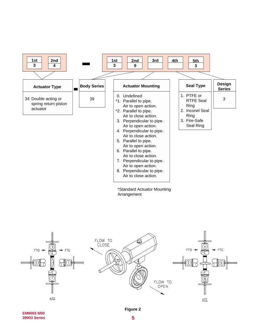
1.6 Numbering System
5EM9003 9/0039003 Series
2nd4
2nd9
5th3
4th3rd1st3
1st3
Figure 2
Seal Type
1. PTFE orRTFE SealRing
2. Inconel SealRing
3. Fire-SafeSeal Ring
Body Series
3934 Double acting orspring return pistonactuator
Actuator TypeDesignSeries
3
Actuator Mounting
0. Undefined*1. Parallel to pipe.
Air to open action.*2. Parallel to pipe.
Air to close action. 3. Perpendicular to pipe.
Air to open action. 4. Perpendicular to pipe.
Air to close action.5. Parallel to pipe.
Air to open action. 6. Parallel to pipe.
Air to close action. 7. Perpendicular to pipe.
Air to open action. 8. Perpendicular to pipe.
Air to close action.
*Standard Actuator MountingArrangement

EM9003 9/0039003 Series6
1.7 Operating PressuresAll Masoneilan HPBVs may be applied to full ANSIratings. However, different materials of constructionmay affect the rated pressure. The shut-off pressurerating is determined by the valve shaft and disc materialsas well as the seat design, and is reflected on the metalidentification tag attached to the valve.
1.8 Seat AlternativesMasoneilan HPBVs have three alternatives, all of whichare bi-directional.
Soft Seats provide tight shut-off to zero leakagespecifications. Standard Soft Seat material includesvirgin TFE or reinforced TFE (RTFE).
Fire-Safe Seats are designed for critical pipingapplications in installations such as Refinery andPetrochemical Plants. These seats are a combination ofboth metal and soft seats with the metal seat beingdesigned to function during and after a fire. Valves ofthis type are referred to as “Fire-Safe” and are tested tomeet API 607 “Fire-Safe” specifications and operationcriteria.
Metal Seats are well suited for higher temperatureapplications and provide shut-off to ANSI B16.104Class IV.
1.9 Offset Disc DesignAll Masoneilan HPBVs have both off-set discs andeccentric shafts. The off-set is applicable to the discedge seating surface relative to the shaft center line. Byoff-setting the seating surface from the rotational centerline, a contact with the seat is possible throughout the360° circumference. The shaft is eccentric in the bodyby 0.060 inches and this enhances seat life by impartinga camming action to the disc as it rotates both in and outof the seat. Seat wear points are eliminated at the topand bottom of the disc and operating torque is reduced.
Soft SeatProfile
Fire-Safe Seat Profile
Metal SeatProfile
Figure 3
Figure 4
Figure 5
Figure 6

7EM9003 9/0039003 Series
Cap Screw Retainer(The retainer is held to the valve body by cap screws recessed in the retainer face.)
Wedge Ring Retainer(A wedge ring is forced outward into a groove machined in the body by the insertion of set screws in the face of the retainer.)
1.10 Seat Retainer AlternativesMasoneilan HPBVs are designed to be easily maintainedand, in particular, to allow rapid and simple replacementof the seat. The seat is held in the valve body by a seatretainer which, when assembled, becomes part of the
raised face flange mating surface. Two types of seatretainer fastening designs are used in MasoneilanHPBVs.
Figure 7
Figure 8

EM9003 9/0039003 Series8
Installation Recommendations
2.1 Valve RatingsMasoneilan HPBVs are intended for use at the pressureand temperatures indicated on the metal nameplateattached to each individual valve. Check the valveoperating temperature and pressure ratings on the valvenameplate before proceeding with installation.
2.2 Seat Upstream vs. Seat DownstreamAlthough all Masoneilan seat designs are completely bi-directional, every effort should be made to install thevalve with pressure and flow from the seat side of thevalve (seat upstream). Positive shutoff will be achievedwith the valve in either orientation. However, installationwith the seat in the upstream position will result in longerservice life and lower torque values.
2.3 Disc ClearancesPrior to installing the valve, it is important to make sure theID of the pipe and pipe flanges is large enough to allow thedisc edge to swing into the opening without interference.Damage to the disc edge can severely affect theperformance of the valve. Pipe schedule compatibility forMasoneilan valves is shown in Section 1.5 of this manual.
2.4 Opening RotationThe Masoneilan valve is designed to open withcounterclockwise rotation of the shaft, and to close withclockwise rotation of the shaft when viewed from abovewith the shaft in the vertical position. An overtravel stopis provided in the body to prevent overtravel of the discin the wrong direction. This stop is not to be used as adisc position stop. Contact with this stop means the dischas travelled past the seat.
2.5 Installation PositionTo prevent damage during installation, the valve discmust be fully closed before installing the valve in the line.It is preferable to install HPBVs with the shaft horizontal.This is important for valves applied to fluids whichcontain particulates. For HPBVs 16” and larger,installation should always be made with the shaft in thehorizontal position.
2.6 Valve and Flange PreparationIf the valve and mating pipe are properly preparedfor installation, future problems can be avoided. All valveand pipe flange faces should be free of dirt, grit,indentations, or surface irregularities which may disruptflange sealing and cause external leakage. The valveseat and disc sealing surface should also be inspected toeliminate any dirt or foreign material that will adverselyaffect the operation of the valve.
2.7 Installation ToolsThe only tool required in the installation of a MasoneilanHPBV is a wrench suitable for tightening the flange boltsand/or nuts required to secure the valve in-line. A hoistmay be required for handling valves 10” and larger.Smaller sized valves can usually be installed by hand.Temporary pipe supports may be used to keep matingflange faces parallel in order to aid in valve installation.
2.8 Required BoltingThe tables outlined on the following pages are furnishedto provide information regarding the size, type, andquantity of bolting recommended for the installationof Masoneilan HPBVs. These tables are intended for useas a planning and procurement guide. Allrecommendations are based on pipe flanges inaccordance with ANSI B16.5 for 2” through 24” valvesand ANSI B16.47 Class A for valves 30” and larger.Flange bolting is not included with the valve shipment.
2.9 Unpacking and Storage Instructions1. Check the packing list against the valve received to
verify that the size, material, and trim are correct.2. Check to make sure that the valve and operator
were not damaged during shipment.3. When lifting the valve, take care to avoid damage to
the flange faces, disc sealing edge, or operator. Onlarger valves, lifting holes are provided on theperiphery of the valve body to aid in valve handling.
4. If the valve is to be stored before being installed, itshould be protected from harsh environmentalconditions.
5. Store the valve with the disc in the closed position toprotect the sealing edge and the seat.

9EM9003 9/0039003 Series
6. Keep the valve in a clean location, away from dirt,debris and corrosive materials.
7. Keep the valve in a dry area with the flange protectorsattached and on a suitable skid or pallet.
8. Keep the valve in a cool location if possible, out ofdirect sunlight.
2.10 Pre-Installation Procedure1. Remove the protective flange covers from the valve.2. Inspect the valve to be certain the waterway is free
from dirt and foreign matter. Be certain the adjoiningpipeline is free from any foreign material such asrust and pipe scale or welding slag that coulddamage the seat and disc sealing surfaces.
3. Actuators should be mounted on the valve prior toinstallation to facilitate proper alignment of the discin the valve seat.
4. The valve should be in the closed position. Makesure the open and closed positions of the actuatorcorrespond to the counterclockwise to open directionof rotation of the valve.
5. Cycle the valve to the fully open position, then backto the fully closed position, checking the actuatortravel stop settings for proper disc alignment.
6. Check the valve identification tag for valve class,materials, and operating pressure to be sure theyare correct for the application.
WARNING! Personal injury or property damagemay result if the valve is installed where serviceconditions could exceed the valve ratings.
7. Check the flange bolts or studs for proper size,threading and length.
2.11 Valve Installation ProcedureThe Masoneilan 39003 Series High Performance ButterflyValve can be installed in the pipeline with the shaft in thevertical, horizontal, or other intermediate position. Basedon applications experience, however, in media withconcentrations of solid or abrasive particles or mediasubject to solidification buildup, valve performance andservice life will be enhanced by mounting the valve with theshaft in the horizontal position.
All Masoneilan valves are bi-directional and can bemounted in the pipeline in either flow direction; however,the preferred flow direction for all seat styles and materialsis with the seat retainer ring located upstream to providemaximum seat protection.
1. For Wafer Style Valves:A. Loosely install the lower flange bolts to form a
cradle between the flanges. (See Figure 9.)B. Noting the flow direction arrow on the tag, place
the valve and flange gaskets between theflanges, making sure the arrow on the tag pointsin the direction of the flow.
C. Install the remaining flange bolts, shifting thevalves as necessary to permit the bolts to passby or through the valve body.
For Lug Style Valves:A. Noting the flow direction arrow on the tag, place
the valve between the flanges, making sure thearrow on the tag points in the direction of the flow.
B. Install the lower flange bolts loosely, leavingspace for the flange gaskets.
C. After inserting the flange gaskets, install theremaining bolts.
Figure 9

EM9003 9/0039003 Series10
2. Using the sequence shown in Figure 10 tighten theflange bolts evenly to assure uniform gasketcompression.
CAUTION! The valve should be centeredbetween the flanges and gaskets to preventdamage to the disc edge and shaft as a resultof the disc striking the flange, gasket, or pipe.
3. If an actuator is to be used, air hoses or electricityshould be connected to the unit as specified.
4. The valve is now ready for operation.
Remember: Install the valve with the disc inthe FULL CLOSED POSITION.
2.12 Actuator Installation1. Actuator Air Piping
The Model 33 actuator used with the HighPerformance Butterfly Valve is designed to accept1/4” NPT air supply piping. Use 1/4” OD tubing orequivalent for all air lines. If the air line exceeds25 ft. in length, or the valve is equipped with volumeboosters, 3/8” tubing is preferred. All connectionsmust be free of leaks.
Caution: Do not exceed loading pressureindicated on a warning tag located on theupper diaphragm case.
2. Changing Actuator PositionFor each valve action, air to open or air to close, theactuator and bracket may be mounted in any one offour recommended positions (see Figure 1). Actuatorposition is usually determined by adjacent piping,obstacles of various types or piping arrangements.Valves may be rotated 180° around the axis of theshaft, if necessary. In such a case, no disassemblyis required, other than repositioning gauges so theyare not upside down. (However, note caution inFigure 1). Note also that the preferred flow directionis reversed. If it becomes necessary to rotate theactuator position 90°, partial disassembly is required.Depending on whether the valve is or is not equippedwith a handwheel, select the appropriate section inthis instruction and proceed.
3. Changing Actuator ActionFor the positions shown in Figure 1, the valve actionis air to open or air to close. In both cases theactuator stem extends with admission of air to theactuator. Changing valve action requires partialdisassembly in repositioning the actuator to theother hole in the bracket and reorientation of linkage.Refer to Figures 19 and 20. If the valve is equippedwith a handwheel, it must be repositioned to theopposite side of the bracket.
Note: The handwheel is always installed so itoperates against the actuator spring force.The handwheel is always located on the sameside of the bracket as the actuator (see Figures19 and 20). Depending on whether the valveis or is not equipped with a handwheel, selectthe appropriate section on disassembly andproceed.
Figure 10

11EM9003 9/0039003 Series
2.13 Bolting Dimensions
Class 150 2” – 24”Class 150 30” – 48”
Lug Valves Wafer Valves
Studs & Nuts Machine Bolts Studs & Nuts
Valve Valve Thread Qty Length Qty Length Qty Length Qty Length Qty LengthSize Series Size C C D D F F G G E E
2” G 5/8-11 4 2.50 4 2.50 4 1.63 4 1.63 4 5.503” G 5/8-11 4 3.25 4 2.50 4 2.25 4 1.63 4 6.004” G 5/8-11 8 3.00 8 2.75 8 2.12 8 1.88 8 6.006” G 3/4-10 8 3.50 8 3.00 8 2.50 8 1.88 8 6.508” G 3/4-10 8 3.75 8 3.25 8 2.70 8 2.13 8 7.00
10” G 7/8-9 12 4.25 12 3.50 12 3.00 12 2.25 12 7.5012” G 7/8-9 12 4.75 12 3.50 12 3.45 12 2.35 12 8.5014” G 1-8 12 5.00 12 4.00 12 3.75 12 2.70 12 9.5016” G 1-8 16 5.50 16 4.25 16 4.12 16 2.75 16 10.0018” G 11/8-8 16 5.75 16 4.75 16 4.38 16 3.25 16 11.0020” G 11/8-8 16 6.75 16 4.75 16 5.12 16 3.25 16 11.50
G 11/8-8 4** 5.50 4** 4.75 4** 4.12 4** 3.25 4** 5.5024” G 11/8-8 20 7.25 20 5.75 20 5.63 20 4.25 20 13.0030” H 11/4-8 24 7.75 24 7.75 24 6.25 24 6.25 24 16.00
H 11/4-8 4** 6.50 4** 6.25 4** 5.00 4** 4.63 4** 6.5036” H 11/2-8 28 9.50 28 9.50 28 7.75 28 7.75 28 19.50
H 11/2-8 4** 7.50 4** 7.25 4** 5.75 4** 5.50 4** 7.5042” H 11/2-8 32 10.00 32 10.00 32 8.50 32 8.25 32 20.50
H 11/2-8 4** 8.25 4** 7.50 4** 6.50 4** 5.75 4** 8.2548” H 11/2-8 40 11.75 40 11.00 40 9.88 40 9.25 40 23.00
H 11/2-8 4** 9.00 4** 8.25 4** 7.12 4** 6.50 4** 9.00
Length of machine bolts based on:1. Gasket thickness of 0.06 inches.2. Minimum flange thickness of weld neck flanges per ANSI B16.5 and B16.47 Series A.**Variation to specified bolting length may result in improper installation.
Every effort is made to provide accurate information, but no liability for claims arising from erroneous data will be accepted by Dresser.

EM9003 9/0039003 Series12
ANSI Class 300 2” – 24”MSS SP-44 Class 300 30”
Lug Valves Wafer ValvesBolt Engagement in Valve* Studs & Nuts Machine Bolts Studs & Nuts
Valve Valve Thread Qty Length Qty Length Qty Length Qty Length Qty Length Qty Length Qty Length
Size Series Size A A B B C C D D F F G G E E2” G 5/8-11 8 .940 8 .570 8 2.25 8 2.62 8 1.50 8 2.00 8 5.253” G 3/4-10 8 1.034 8 .826 8 3.00 8 3.00 8 2.12 81 2.00 8 6.004” G 3/4-10 8 1.196 8 .870 8 3.50 8 3.25 8 2.50 8 2.00 8 6.506” G 3/4-10 12 1.301 12 .929 12 3.75 12 3.50 12 2.75 12 2.25 12 7.008” G 7/8-9 12 1.702 12 1.128 12 4.50 12 4.00 12 3.25 12 2.75 12 8.25
10” G 1-8 16 1.867 16 1.300 16 5.00 16 4.50 16 3.25 16 3.12 14 9.25G 1-8 - - - - - - - - - - - 4** 5.00
12” G 11/8-8 16 2.057 16 1.475 16 5.50 16 5.00 16 4.00 16 3.38 12 10.00G 11/8-8 - - - - - - - - - - - - 8** 5.25
14” H 11/8-8 16 2.442 16 2.118 16 6.00 16 5.75 16 4.62 16 4.25 16 11.50H 11/8-8 4** 1.608 4** 1.267 4** 5.25 4** 4.75 4** 3.75 4** 3.44 8** 5.25
16” H 11/4-8 16 2.562 16 2.628 16 6.50 16 6.50 16 4.88 16 4.88 16 13.00H 11/4-8 4** 1.538 4** 1.588 4** 5.25 4** 5.25 4** 3.88 4** 4.25 8** 5.25
18” H 11/4-8 20 2.875 20 2.890 20 7.00 20 7.00 20 5.25 20 5.25 20 14.00H 11/4-8 4** 1.675 4** 1.437 4** 5.50 4** 5.50 4** 4.00 4** 3.88 8** 5.50
20” H 11/4-8 20 3.184 20 3.006 20 7.50 20 7.25 20 5.69 20 5.69 20 14.50H 11/4-8 4** 1.681 4** 1.750 4** 5.75 4** 5.50 4** 4.19 4** 4.00 8** 5.75
24” H 11/2-8 20 3.560 20 3.510 20 8.25 20 8.25 20 6.31 20 6.25 20 16.50H 11/2-8 4** 1.800 4** 1.750 4** 6.25 4** 6.25 4** 4.56 4** 4.50 8** 6.25
30” H 13/4-8 24 4.331 24 4.429 24 10.25 24 10.50 24 7.88 24 7.88 24 20.50H 13/4-8 4** 2.039 4** 2.071 4** 8.00 4** 8.00 4** 5.44 4** 5.47 8** 8.00
ANSI Class 600 3” – 14”
Lug Valves Wafer ValvesBolt Engagement in Valve* Studs & Nuts Machine Bolts Studs & Nuts
Valve Valve Thread Qty Length Qty Length Qty Length Qty Length Qty Length Qty Length Qty LengthSize Series Size A A B B C C D D F F G G E E
3” G 3/4-10 8 1.034 8 1.026 8 3.50 8 3.50 8 2.25 8 2.38 8 7.004” G 7/8-9 8 1.274 8 1.165 8 3.50 8 3.25 8 2.75 8 2.75 8 7.756” G 1-8 12 1.274 12 1.306 12 4.75 12 4.75 12 3.25 12 3.25 12 9.508” G 11/8-8 12 1.794 12 1.795 12 5.75 12 5.75 12 4.12 12 4.12 12 11.50
10” H 11/4-8 12 2.495 12 2.000 12 6.75 12 6.25 12 5.00 12 4.50 12 13.00H 11/4-8 4** 1.375 4** 2.000 4** 5.50 4** 6.25 4** 3.88 4** 4.50 8** 6.25
12” H 11/4-8 16 2.683 16 2.697 16 7.00 16 7.00 16 5.38 16 5.38 16 14.00H 11/4-8 4** 1.325 4** 1.765 4** 5.25 4** 6.00 4** 4.00 4** 4.38 8** 6.00
14” H 13/8-8 16 2.994 16 2.996 16 7.50 16 7.50 16 CF 16 CF 16 15.00H 13/8-8 4** 1.506 4** 1.869 4** 6.00 4** 6.50 4** CF 4** CF 8** 6.50
*Bolt lengths “A” & “B” are from face of valve body to minimum depth in lug. Flange & gasket thickness must be added to calculateminimum bolt length.
**Special length required for tapped blind holes on either side of the valve shaft at the top and bottom ends of the valve body.
2.13 Bolting Dimensions (cont.)
13EM9003 9/0039003 Series
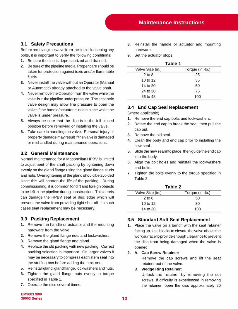
3.1 Safety PrecautionsBefore removing the valve from the line or loosening anybolts, it is important to verify the following conditions:1. Be sure the line is depressurized and drained.2. Be sure of the pipeline media. Proper care should be
taken for protection against toxic and/or flammablefluids.
3. Never install the valve without an Operator (Manualor Automatic) already attached to the valve shaft.
4. Never remove the Operator from the valve while thevalve is in the pipeline under pressure. The eccentricvalve design may allow line pressure to open thevalve if the handle/actuator is not in place while thevalve is under pressure.
5. Always be sure that the disc is in the full closedposition before removing or installing the valve.
6. Take care in handling the valve. Personal injury orproperty damage may result if the valve is damagedor mishandled during maintenance operations.
3.2 General MaintenanceNormal maintenance for a Masoneilan HPBV is limitedto adjustment of the shaft packing by tightening downevenly on the gland flange using the gland flange studsand nuts. Overtightening of the gland should be avoidedsince this will shorten the life of the packing. Duringcommissioning, it is common for dirt and foreign objectsto be left in the pipeline during construction. This debriscan damage the HPBV seat or disc edge which willprevent the valve from providing tight shut-off. In suchcases seat replacement may be necessary.
3.3 Packing Replacement1. Remove the handle or actuator and the mounting
hardware from the valve.2. Remove the gland flange nuts and lockwashers.3. Remove the gland flange and gland.4. Replace the old packing with new packing. Correct
packing selection is important. On larger valves itmay be necessary to compress each stem seal intothe stuffing box before adding the next one.
5. Reinstall gland, gland flange, lockwashers and nuts.6. Tighten the gland flange nuts evenly to torque
specified in Table 1.7. Operate the disc several times.
8. Reinstall the handle or actuator and mountinghardware.
9. Set the actuator stops.
Table 1Valve Size (in.) Torque (in.-lb.)
2 to 8 2510 to 12 3514 to 20 5024 to 30 7536 to 48 100
3.4 End Cap Seal Replacement(where applicable)1. Remove the end cap bolts and lockwashers.2. Rotate the end cap to break the seal, then pull the
cap out.3. Remove the old seal.4. Clean the body and end cap prior to installing the
new seal.5. Slide the new seal into place, then guide the end cap
into the body.6. Align the bolt holes and reinstall the lockwashers
and bolts.7. Tighten the bolts evenly to the torque specified in
Table 2.
Table 2Valve Size (in.) Torque (in.-lb.)
2 to 8 5010 to 12 8014 to 30 100
3.5 Standard Soft Seat Replacement1. Place the valve on a bench with the seat retainer
facing up. Use blocks to elevate the valve above thework surface to provide enough clearance to preventthe disc from being damaged when the valve isopened.
2. A. Cap Screw Retainer:Remove the cap screws and lift the seatretainer out of the valve.
B. Wedge Ring Retainer:Unlock the retainer by removing the setscrews. If difficulty is experienced in removingthe retainer, open the disc approximately 20
Maintenance Instructions
EM9003 9/0039003 Series14
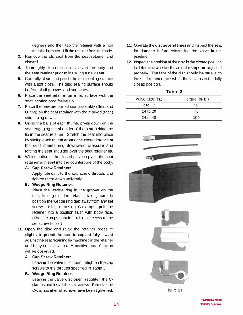
degrees and then tap the retainer with a nonmetallic hammer. Lift the retainer from the body.
3. Remove the old seat from the seat retainer anddiscard.
4. Thoroughly clean the seat cavity in the body andthe seat retainer prior to installing a new seat.
5. Carefully clean and polish the disc sealing surfacewith a soft cloth. The disc sealing surface shouldbe free of all grooves and scratches.
6. Place the seat retainer on a flat surface with theseat locating area facing up.
7. Place the new preformed seat assembly (Seat andO-ring) on the seat retainer with the marked (tape)side facing down.
8. Using the balls of each thumb, press down on theseat engaging the shoulder of the seat behind thelip in the seat retainer. Stretch the seat into placeby sliding each thumb around the circumference ofthe seat maintaining downward pressure andforcing the seat shoulder over the seat retainer lip.
9. With the disc in the closed position place the seatretainer with seat into the counterbore of the body.A. Cap Screw Retainer:
Apply lubricant to the cap screw threads andtighten them down uniformly.
B. Wedge Ring Retainer:Place the wedge ring in the groove on theoutside edge of the retainer taking care toposition the wedge ring gap away from any setscrew. Using opposing C-clamps, pull theretainer into a position flush with body face.(The C-clamps should not block access to theset screw holes.)
10. Open the disc and relax the retainer pressureslightly to permit the seat to expand fully inwardagainst the seat retaining lip machined in the retainerand body seat cavities. A positive “snap” actionwill be observed.A. Cap Screw Retainer:
Leaving the valve disc open, retighten the capscrews to the torques specified in Table 3.
B. Wedge Ring Retainer:Leaving the valve disc open, retighten the C-clamps and install the set screws. Remove theC-clamps after all screws have been tightened.
11. Operate the disc several times and inspect the seatfor damage before reinstalling the valve in thepipeline.
12. Inspect the position of the disc in the closed positionto determine whether the actuator stops are adjustedproperly. The face of the disc should be parallel tothe seat retainer face when the valve is in the fullyclosed position.
Table 3Valve Size (in.) Torque (in-lb.)
2 to 12 50
14 to 20 75
24 to 48 100
Figure 11

15EM9003 9/0039003 Series
3.6 Fire-Safe and Metal Seat Replacement1. Follow Steps 1 and 2 of Soft Seat Replacement
instructions.2. Remove old soft seat and graphite gaskets and
discard. Clean and inspect the metal seat.3. If metal seat is scored, bent or otherwise damaged
it will require replacement.4. Thoroughly clean the seat cavity in the body and the
seat retainer prior to installing the new seat.5. Carefully clean and polish the disc edge sealing
surface with a soft cloth. The disc sealing surfaceshould be free of all grooves and scratches.
6. A graphite gasket is required on both sides of themetal seat. Gaskets can be made from self-adhesivegraphite tape as follows:A. Suggested graphite tape size:
2” – 12” valves – 1/2” wide14” – 48” valves – 1” wide
B. To install the tape, peel off 6” of backing paperat a time. Apply the tape to the metal seatcovering the flat outer edge area on both sides.Overlap the two ends of the tape a minimum of1/8 inch.
Note: It is important that both sides havegaskets.
C. Smooth tape as much as possible by hand.Slight roughness is acceptable and will bepressed flat during final assembly. Avoidtearing tape. If a tear occurs, tape should beoverlapped a minimum of 1/8 inch. Trim excesstape from outside diameter of the seat.
D. If cap screw retainer design, bolt holes in metalseat should be opened by slitting an “X” in thehole. Do not attempt to cut round holes.
7. For Fire-Safe valves, place the preformed seatassembly in the body seat cavity with the marked(tape) side up. For metal seated valves, place the316SS back-up ring in the body seat cavity.
8. Place the metal seat with the graphite gaskets onthe TFE seat or 316SS back-up ring already in thebody. The metal seat should be installed with therounded edge down against the TFE seat or the316SS back-up ring.
9. Follow steps 9 thru 12 of Soft Seat Replacementinstructions.
3.7 Disc, Shaft and Bearing Replacement
Masoneilan uses a wedge pin method of disc/shaftpinning. This method permits the replacement of eithera disc or a shaft since they are not required to bematched sets.1. Remove any actuator and mounting bracket from
top of valve.2. Remove all top and bottom packing and/or end
seals as required.3. To prepare for removal of existing wedge pins, grind
away any disc material that has been peened overpin heads.
4. A. For Through Shaft Design:Using a punch approximately the same size asthe wedge pins, drive each pin out of the dischub from the non-peened side of the disc to thepeened side of the disc.
B. For Split Shaft Design:Pull the wedge pins out of the disc hub using thethreaded holes on top of each pin and a jackscrew.
5. Support the valve body and disc on a flat surface inthe horizontal position. Slowly remove shaft(s).
6. Remove the disc from the body.7. To remove bearings, cut or grind a slot lengthwise in
each bearing in order to be able to collapse bearingprior to removal. Be careful not to damage bearingseating bore within the body.
8. Clean all components thoroughly.9. Inspect all parts for damage prior to reassembly.
Damaged parts should be repaired or replaced withnew parts.
Figure 12
EM9003 9/0039003 Series16
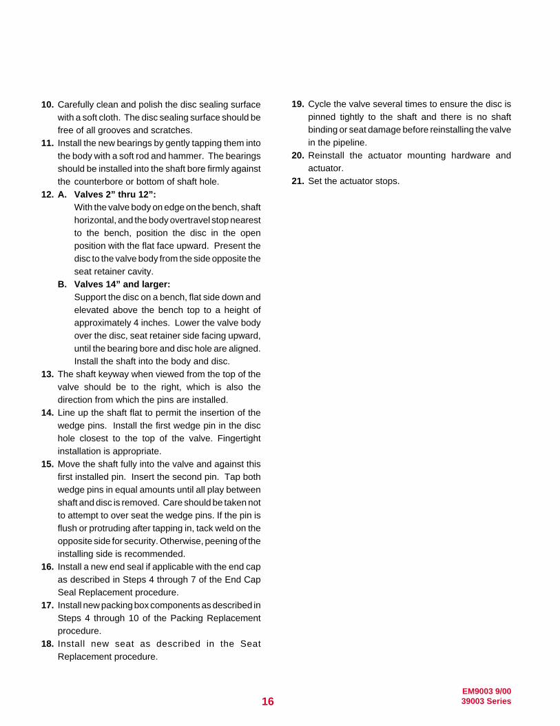
10. Carefully clean and polish the disc sealing surfacewith a soft cloth. The disc sealing surface should befree of all grooves and scratches.
11. Install the new bearings by gently tapping them intothe body with a soft rod and hammer. The bearingsshould be installed into the shaft bore firmly againstthe counterbore or bottom of shaft hole.
12. A. Valves 2” thru 12”:With the valve body on edge on the bench, shafthorizontal, and the body overtravel stop nearestto the bench, position the disc in the openposition with the flat face upward. Present thedisc to the valve body from the side opposite theseat retainer cavity.
B. Valves 14” and larger:Support the disc on a bench, flat side down andelevated above the bench top to a height ofapproximately 4 inches. Lower the valve bodyover the disc, seat retainer side facing upward,until the bearing bore and disc hole are aligned.Install the shaft into the body and disc.
13. The shaft keyway when viewed from the top of thevalve should be to the right, which is also thedirection from which the pins are installed.
14. Line up the shaft flat to permit the insertion of thewedge pins. Install the first wedge pin in the dischole closest to the top of the valve. Fingertightinstallation is appropriate.
15. Move the shaft fully into the valve and against thisfirst installed pin. Insert the second pin. Tap bothwedge pins in equal amounts until all play betweenshaft and disc is removed. Care should be taken notto attempt to over seat the wedge pins. If the pin isflush or protruding after tapping in, tack weld on theopposite side for security. Otherwise, peening of theinstalling side is recommended.
16. Install a new end seal if applicable with the end capas described in Steps 4 through 7 of the End CapSeal Replacement procedure.
17. Install new packing box components as described inSteps 4 through 10 of the Packing Replacementprocedure.
18. Install new seat as described in the SeatReplacement procedure.
19. Cycle the valve several times to ensure the disc ispinned tightly to the shaft and there is no shaftbinding or seat damage before reinstalling the valvein the pipeline.
20. Reinstall the actuator mounting hardware andactuator.
21. Set the actuator stops.
17EM9003 9/0039003 Series
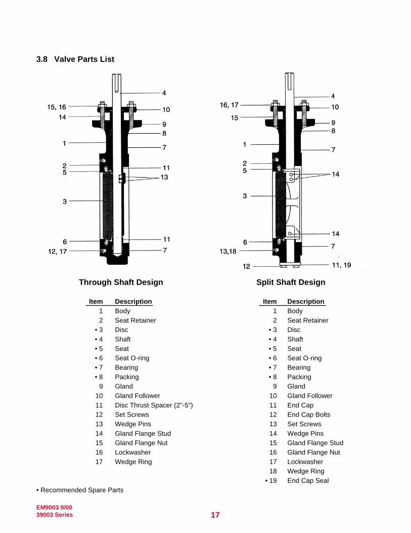
Through Shaft Design Split Shaft Design
Item Description Item Description1 Body 1 Body2 Seat Retainer 2 Seat Retainer
• 3 Disc • 3 Disc• 4 Shaft • 4 Shaft• 5 Seat • 5 Seat• 6 Seat O-ring • 6 Seat O-ring• 7 Bearing • 7 Bearing• 8 Packing • 8 Packing
9 Gland 9 Gland10 Gland Follower 10 Gland Follower11 Disc Thrust Spacer (2"-5") 11 End Cap12 Set Screws 12 End Cap Bolts13 Wedge Pins 13 Set Screws14 Gland Flange Stud 14 Wedge Pins15 Gland Flange Nut 15 Gland Flange Stud16 Lockwasher 16 Gland Flange Nut17 Wedge Ring 17 Lockwasher
18 Wedge Ring• 19 End Cap Seal
• Recommended Spare Parts
3.8 Valve Parts List

EM9003 9/0039003 Series18
3.9 Remote Actuator (Male Drive) Mounting Procedure
1. Position the disc in the closed position.2. Install the actuator mounting bracket on the valve
body with the actuator mounting holes facing up-ward. Fasten the bracket securely in place with theappropriate machine bolts and lockwashers. Tightento torque specified in Table 4.
3. Install the drivekey in the keyway of the shaft. Tapthe key in place to ensure it is fully seated.
4. Install the drive coupling on the shaft by lining up theproper keyway in the coupling with the key in theshaft.
5. Rotate the actuator shaft to the full clockwise position.Align the drive coupling with the actuator shaft andinstall the actuator on the mounting bracket.
6. Fasten the actuator to the mounting bracket with theappropriate machine bolts and lockwashers. Tightento torque specified in Table 4. It may be necessaryto slightly rotate the actuator shaft to align themounting holes in the actuator with the mountingbracket.
7. Adjust the stops in the actuator to position the faceof the disc parallel with the face of the valve body inthe closed position and perpendicular to the face ofthe valve body in the open position.
Caution: The overtravel stop in the valvebody is not to be used as an actuator stop.
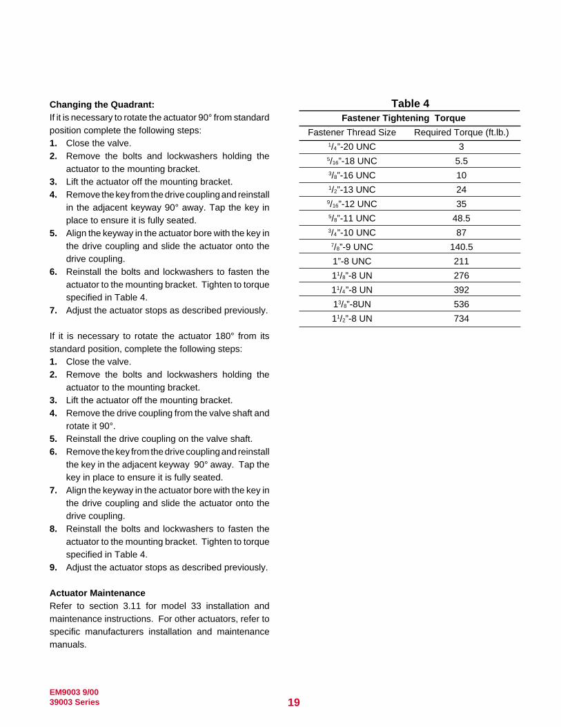
Changing the Quadrant:If it is necessary to rotate the actuator 90° from standardposition, complete the following steps:1. Close the valve.2. Remove the bolts and lockwashers holding the
actuator to the mounting bracket. Lift the actuatoroff the mounting bracket.
3. Remove the drive coupling from the valve shaft androtate it 90° to the adjacent keyway.
4. Reinstall the drive coupling on the valve shaft.5. Align the drive coupling with the actuator shaft and
install the actuator on the mounting bracket.6. Reinstall the bolts and lockwashers to fasten the
actuator to the mounting bracket. Tighten to torquespecified in Table 4.
7. Adjust the actuator stops as described above.
If it is necessary to rotate the actuator 180° fromstandard position, complete the following steps:1. Close the valve.2. Remove the bolts and lockwashers holding the
actuator to the mounting bracket.3. Lift the actuator off the mounting bracket. Rotate the
actuator 180°.4. Align the drive coupling with the actuator shaft and
install the actuator on the mounting bracket.5. Reinstall the bolts and lockwashers to fasten the
actuator to the mounting bracket. Tighten to torquespecified in Table 4.
6. Adjust the actuator stops as described previously.
3.10 Remote Actuator (Female Drive) Mounting Procedure
1. Position the disc in the closed position.2. Install the actuator mounting bracket on the valve
body with the actuator mounting holes facing up.Fasten the bracket securely in place with theappropriate machine bolts and lockwashers.
3. Install the drive key in the shaft. Tap the key in placeto ensure it is fully seated.
4. Install the drive coupling on the shaft by lining up theproper coupling keyway with the key in the shaft.
5. Install the drive key in the drive coupling. Tap thekey in place to ensure it is properly seated.
6. Rotate the actuator to the full clockwise position.Align the keyway in the actuator bore with the key inthe drive coupling and slide the actuator on the drivecoupling.
7. Fasten the actuator to the mounting bracket with theappropriate machine bolts and lockwashers. It maybe necessary to rotate the actuator slightly to alignthe actuator with the mounting bracket. Tighten totorque specified in Table 4.
8. Adjust the stops in the actuator to position the faceof the disc parallel with the face of the valve body inthe closed position and perpendicular to the face ofthe valve body in the open position.
Caution: The overtravel stop in the valvebody is not to be used as an actuator stop.
19EM9003 9/0039003 Series
Changing the Quadrant:If it is necessary to rotate the actuator 90° from standardposition complete the following steps:1. Close the valve.2. Remove the bolts and lockwashers holding the
actuator to the mounting bracket.3. Lift the actuator off the mounting bracket.4. Remove the key from the drive coupling and reinstall
in the adjacent keyway 90° away. Tap the key inplace to ensure it is fully seated.
5. Align the keyway in the actuator bore with the key inthe drive coupling and slide the actuator onto thedrive coupling.
6. Reinstall the bolts and lockwashers to fasten theactuator to the mounting bracket. Tighten to torquespecified in Table 4.
7. Adjust the actuator stops as described previously.
If it is necessary to rotate the actuator 180° from itsstandard position, complete the following steps:1. Close the valve.2. Remove the bolts and lockwashers holding the
actuator to the mounting bracket.3. Lift the actuator off the mounting bracket.4. Remove the drive coupling from the valve shaft and
rotate it 90°.5. Reinstall the drive coupling on the valve shaft.6. Remove the key from the drive coupling and reinstall
the key in the adjacent keyway 90° away. Tap thekey in place to ensure it is fully seated.
7. Align the keyway in the actuator bore with the key inthe drive coupling and slide the actuator onto thedrive coupling.
8. Reinstall the bolts and lockwashers to fasten theactuator to the mounting bracket. Tighten to torquespecified in Table 4.
9. Adjust the actuator stops as described previously.
Actuator MaintenanceRefer to section 3.11 for model 33 installation andmaintenance instructions. For other actuators, refer tospecific manufacturers installation and maintenancemanuals.
Table 4Fastener Tightening Torque
Fastener Thread Size Required Torque (ft.lb.)1/4”-20 UNC 35/16”-18 UNC 5.53/8”-16 UNC 101/2”-13 UNC 24
9/16”-12 UNC 355/8”-11 UNC 48.53/4”-10 UNC 877/8”-9 UNC 140.5
1”-8 UNC 211
11/8”-8 UN 276
11/4”-8 UN 392
13/8”-8UN 536
11/2”-8 UN 734

EM9003 9/0039003 Series20
3.11 33 Actuator MaintenanceThis section addresses the complete disassembly of theModel 33 Spring Diaphragm Actuator in order to gainaccess for repair or replacement of components. If onlypartial disassembly is required, such as when changingvalve action, refer only to the appropriate section. It ishighly recommended that the unit be removed from theline to perform maintenance.
1. Actuator Removal
Caution: When working on air to closeunits, be certain that the disc is not jammedin the closed position with the actuator springexerting force to open the valve. In such acase, while disassembling, the disc couldsuddenly snap open possibly causing injury.When the actuator stem is fully extended,the spring is exerting force in the oppositedirection. If the disc is jammed closed, on anair to close unit, use external air pressure tohold the actuator in a closed position andcomplete the necessary steps in this sectionto disconnect the pivot pin (5), then releaseair pressure from the actuator, insuring rodand bearing (71) separates from lever (14)and actuator stem (54) fully retracts.
A. If equipped with a handwheel, it must be rotatedto the disengaged position.
B. Remove positioner and air piping to upperdiaphragm case (61).
C. Remove side covers (38), front cover (6) andbottom cover (41).
D. Insure actuator stem is fully retracted (seecaution above).
E. Remove retaining rings (4), pivot pin (5) andspacers (3).
Note: The spacers (3) are only used onunits equipped with the handwheel.
F. Remove the hex nuts (52) and lock washers(53) and lift actuator from bracket.
2. Actuator Disassembly
Caution: The upper diaphragm case (61) isunder spring tension. A warning tag (74)is attached to each of three long tensionbolts (72). The tension nuts (73) attached tothe tension bolts (72) must be removedevenly, and must also be the last itemsdisassembled. The following proceduremust be followed to avoid injury.
A. Loosen and remove all short cap screws (63)and hex nuts (64).
B. Loosen each tension nut (73) approximatelythree full turns.
Caution: The upper diaphragm case (61)should separate as the tension nuts areloosened the three turns. If it does not, beforeproceeding, separate the upper diaphragmcase (61) by tapping around the circumferenceor inserting a screwdriver between the upperand lower case (61) and (68).
C. Continue loosening the tension nuts (73) evenly(approximately three turns each time) ensuringthat the upper diaphragm case (61) anddiaphragm (62) continue to separate.
Note: Continue Step C until the tensionnuts (73) can be easily removed by handindicating the upper diaphragm case (61) isnot under spring tension.
D. Remove tension bolts (72) and upper diaphragmcase (61).
E. Remove diaphragm/diaphragm plate sub-assembly from the actuator.
F. Remove retaining clips (57) and push out pin(56). Inspect for damage and/or wear in clevis(55), lever (14), clevis pins (56, 5) and rod endbearing (71). Replace if necessary.

21EM9003 9/0039003 Series
3. Handwheel RemovalA. Rotate handwheel to the disengaged position.B. Remove bottom cover (41).C. Remove retaining clips (21) and clevis pin (20).D. Loosen and remove cap screws (24), lock
washers (25) and remove handwheel andbracket subassembly.
4. Handwheel DisassemblyA. Remove pivot pin (26) and remove bracket (23).B. Remove handwheel subassembly from shaft (22).C. Remove handwheel shaft subassembly (59).
Remove retaining ring (28) then loosen andremove locknut (51).
D. Remove bearing brace (31) and bearing (30).E. Remove handwheel pivot (27), O-ring (32) and
thrust washer (29).F. Refer to Section 3.13 for reassembly.
5. Body RemovalA. Refer to Section 1 (Actuator Removal) and
complete Steps A through E.B. If the unit is equipped with a handwheel, refer to
Section 3 (Handwheel Removal) and completeSteps A through D.
C. Loosen indicator arm (2) by loosening clampscrew (13) and nut (50).
Note: At this time, using ink or a small dabof paint, mark the relative position of theshaft to the lever (14) or mark a line on thelever in line with the slot in the end of theshaft. During reassembly these marks willbe used to simplify alignment of the lever onthe shaft.
D. Loosen lever cap screw (15).E. Remove nuts (46), washers (45) and bracket
bolts (44), then remove bolts (43).F. Remove set screw (81) from coupling (79).G. Separate body subassembly and yoke (10)
from bracket (1).H. Slide shaft (77) out of yoke.
3.12 Actuator Diaphragm Replacement
Caution: The upper diaphragm case (61) isunder spring tension. A warning tag (74) isattached to each of three long tension bolts(72). The tension nuts (73) attached to thetension bolts (72) must be removed evenly,and must also be the last itemsdisassembled. The following proceduremust be followed to avoid injury.
1. Isolate the valve, vent process pressure and shut offall electrical signal air and supply lines to the valve.
2. If equipped with a handwheel it must be rotated tothe disengaged position.
3. Remove air supply piping to upper diaphragmcase (61).
4. Remove side covers (38).5. Verify actuator stem (54) and rod end (71) are
securely connected to lever (14) through pivot pin(5) and retaining clips (4) are in place.
6. Loosen and remove all short cap screws (63) andhex nuts (64) in a criss-cross pattern.
7. Loosen each tension nut (73) approximately threefull turns.
Caution: The upper diaphragm case (61)should separate as the tension nuts areloosened the three turns. If it does not,before proceeding, separate the upperdiaphragm case (61) by tapping it aroundthe circumference or inserting a screwdriverbetween the upper and lower case (61-68).
8. Continue loosening the tension nuts (73) evenly,approximately three turns each time and ensuringthe upper diaphragm case (61) and diaphragm (62)continue to separate.
Note: Continue Step 8 until the tension nuts(73) can be easily removed by hand, whichindicates that the upper diaphragm case(61) is no longer under spring tension.
9. Remove tension bolts (72) and upper diaphragmcase (61).

EM9003 9/0039003 Series22
10. Remove diaphragm.11. Clean all mating/sealing surfaces which will come in
contact, diaphragm (62), and diaphragm plate (65).12. Install diaphragm (62) on diaphragm plate (65).
Align bolt holes with holes in lower case (68).13. Determine correct orientation for air inlet and replace
upper diaphragm case (61).14. Install three tension bolts (72) with warning plates
(74) into upper case (61). Ensure bolts are spacedat 120° to each other.
15. Mount upper case (61) on diaphragm plate (65)such that tension bolts pass through holes indiaphragm (62) and lower case (68).
16. Install tension nuts (73) finger tight onto tensionbolts (72).
17. Tighten each tension nut (73) three turns beforeproceeding to the next to ensure actuator spring(67) is evenly loaded. Continue until the diaphragmis firmly sandwiched between the flanges of theupper and lower diaphragm cases. Torque tightentension bolts to 50 in. lb.
18. Install cap screws (63) and nuts (64). Torque tightento 50 in. lb. in a criss-cross pattern. As this will tendto unload the tension bolts (72) repeat torquetightening of tension bolts and cap screws (63) to 50in. lb. in a criss-cross pattern until joint is evenlyloaded to specified torque values.
19. Reconnect air supply.20. Stroke actuator to confirm operation.
3.13 33 Actuator Reassembly1. Actuator Reassembly
A. Replace spring (67) into lower diaphragmcase (68).
B. Replace locknut (70) on rod end bearing (71)and screw rod end bearing into actuatorstem (54).
C. Replace actuator stem (54) into clevis (55).D. Replace clevis pin (56) and secure with cap
screws (58). Install clevis pin (56) and clips (57).E. Refer to Section 3.12 and complete Steps 12
through 20.
2. Reassembly of Yoke and Bracket to ValveA. Install ball bearing (9) into yoke (10).B. Mount intermediate bracket (1) to yoke (10) with
bolts (44), nuts (46), and lockwashers (45).Tighten to appropriate torque value per Table 4.
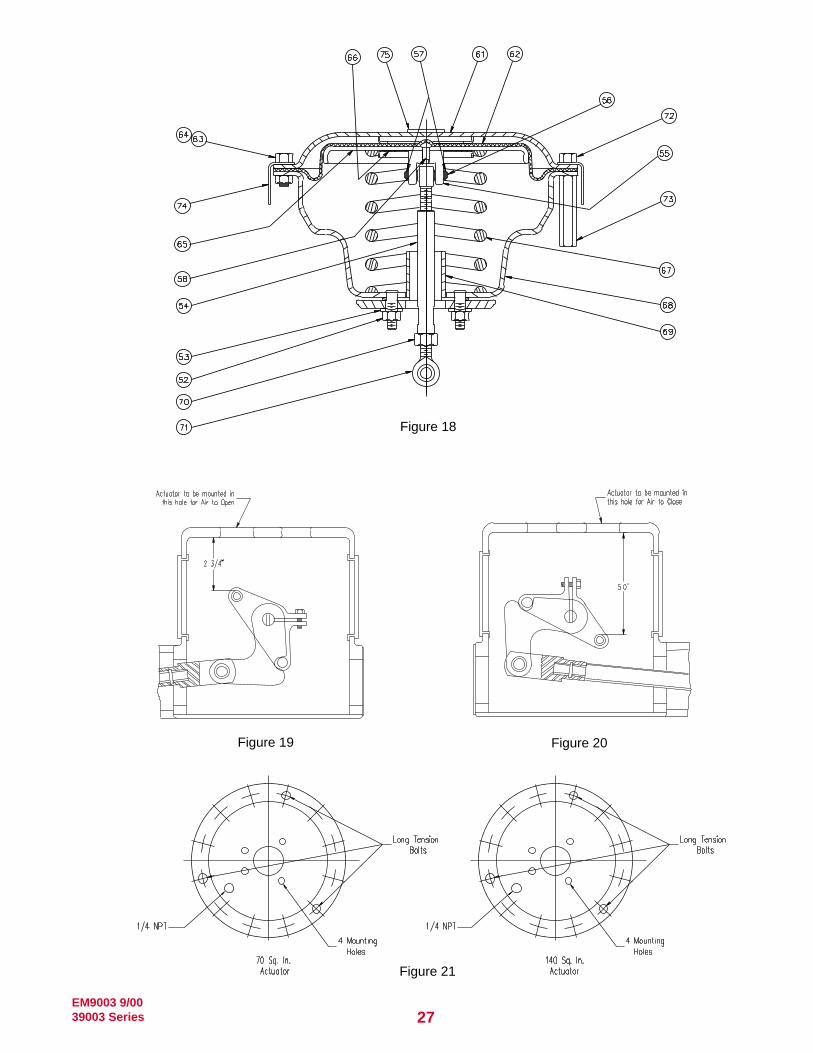
C. Install bearing (76) into yoke (if applicable).D. Determine the required actuator action (air to
close or air to open). Refer to the proper figure(Figure 19 to open, Figure 20 to close). Toobtain proper alignment, the lever must beoriented on the shaft so that the slot in the endof the shaft and arrows or indicator lines arealigned as shown. The distance between thetop of the yoke and the top of the pivot pin mustbe as shown. If the valve is equipped with ahandwheel, proceed to step E. Slide shaft (77)through intermediate bracket (item 1 of Figure15) and partially into yoke (1). With other hand,hold lever (14) and align with the shaft (77) in thedesired orientation, slide shaft through lever.
E. If the valve is equipped with a handwheel, thelever consists of two separate arms that are amatched pair and the handwheel lever (refer toview c-c of Figure 17). Slide shaft (77) throughintermediate bracket (item 1 of Figure 15) andpartially into yoke. The sequence of assemblyis to place one lever (item 4 of Figure 17) overthe shaft (77) in the correct orientation (per StepD). Slide handwheel lever arm (18) onto shaft.Insert pin (17) and slide second lever arm overshaft in the same orientation as the first lever.
F. Slide indicator (item 2 as indicated in Figure 15)loosely over top of shaft (do not tighten clampscrew at this time). Then continue to slide shaftinto yoke until step on shaft (77) contacts ballbearing (9) (as indicated in Figure 15).
G. Install woodruff key (80) in shaft (77). Align key(80) in shaft (77) with keyway in coupling thenslide coupling onto shaft (77).
H. Install key into valve shaft.I. Move valve to closed position. Rotate valve to
required orientation, slide valve shaft throughintermediate bracket. Aligning keyway incoupling with valve key, slide valve shaft intocoupling (79). Tighten set screw (81).
J. Connect valve body to bracket using cap screws(43) and lockwashers. Tighten to appropriatetorque value per Table 4.
23EM9003 9/0039003 Series
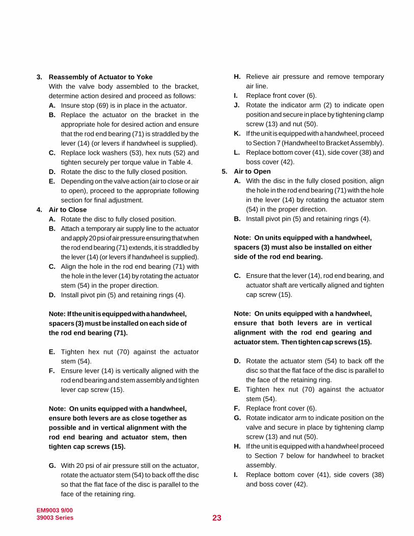
3. Reassembly of Actuator to YokeWith the valve body assembled to the bracket,determine action desired and proceed as follows:A. Insure stop (69) is in place in the actuator.B. Replace the actuator on the bracket in the
appropriate hole for desired action and ensurethat the rod end bearing (71) is straddled by thelever (14) (or levers if handwheel is supplied).
C. Replace lock washers (53), hex nuts (52) andtighten securely per torque value in Table 4.
D. Rotate the disc to the fully closed position.E. Depending on the valve action (air to close or air
to open), proceed to the appropriate followingsection for final adjustment.
4. Air to CloseA. Rotate the disc to fully closed position.B. Attach a temporary air supply line to the actuator
and apply 20 psi of air pressure ensuring that whenthe rod end bearing (71) extends, it is straddled bythe lever (14) (or levers if handwheel is supplied).
C. Align the hole in the rod end bearing (71) withthe hole in the lever (14) by rotating the actuatorstem (54) in the proper direction.
D. Install pivot pin (5) and retaining rings (4).
Note: If the unit is equipped with a handwheel,spacers (3) must be installed on each side ofthe rod end bearing (71).
E. Tighten hex nut (70) against the actuatorstem (54).
F. Ensure lever (14) is vertically aligned with therod end bearing and stem assembly and tightenlever cap screw (15).
Note: On units equipped with a handwheel,ensure both levers are as close together aspossible and in vertical alignment with therod end bearing and actuator stem, thentighten cap screws (15).
G. With 20 psi of air pressure still on the actuator,rotate the actuator stem (54) to back off the discso that the flat face of the disc is parallel to theface of the retaining ring.
H. Relieve air pressure and remove temporaryair line.
I. Replace front cover (6).J. Rotate the indicator arm (2) to indicate open
position and secure in place by tightening clampscrew (13) and nut (50).
K. If the unit is equipped with a handwheel, proceedto Section 7 (Handwheel to Bracket Assembly).
L. Replace bottom cover (41), side cover (38) andboss cover (42).
5. Air to OpenA. With the disc in the fully closed position, align
the hole in the rod end bearing (71) with the holein the lever (14) by rotating the actuator stem(54) in the proper direction.
B. Install pivot pin (5) and retaining rings (4).
Note: On units equipped with a handwheel,spacers (3) must also be installed on eitherside of the rod end bearing.
C. Ensure that the lever (14), rod end bearing, andactuator shaft are vertically aligned and tightencap screw (15).
Note: On units equipped with a handwheel,ensure that both levers are in verticalalignment with the rod end gearing andactuator stem. Then tighten cap screws (15).
D. Rotate the actuator stem (54) to back off thedisc so that the flat face of the disc is parallel tothe face of the retaining ring.
E. Tighten hex nut (70) against the actuatorstem (54).
F. Replace front cover (6).G. Rotate indicator arm to indicate position on the
valve and secure in place by tightening clampscrew (13) and nut (50).
H. If the unit is equipped with a handwheel proceedto Section 7 below for handwheel to bracketassembly.
I. Replace bottom cover (41), side covers (38)and boss cover (42).

EM9003 9/0039003 Series24
6. Handwheel ReassemblyTo reassemble handwheel, proceed as follows:A. Install O-ring (32) in the groove.
Note: Do not lubricate O-Ring.
B. Replace thrust washer (29) and handwheelpivot (27).
Note: The handwheel pivot is installed sothat the recessed end is away from the thrustwasher as shown in Figure 13.
C. Apply a liberal amount of lubricant to the bearingrace (31) and bearing (30) and install ensuringthere is one race on either side of the bearing.
D. Install locknut (51) and finger tighten only.E. Install retaining ring (28).
7. Handwheel to Bracket AssemblyThe handwheel is always installed on the sameside of the bracket as the actuator. To install thehandwheel assembly proceed as follows:A. Insert handwheel shaft (22) through appropriate
bracket hole and onto lever arm (18) and installclevis pin (20) and retaining clips (21).
B. Install handwheel bracket (23), lock washers(25) and cap screws (24) and tighten firmly.
C. Rotate the handwheel subassembly onto theshaft (22) far enough to allow alignment of theholes in the handwheel pivot (27) to align withthe holes in the handwheel bracket (23) andinstall pivot pins (26) and tighten firmly.
D. Connect handwheel shaft S/A (59) to handwheel.E. Rotate the handwheel to the disengaged
position.
Note: The disengaged position is achievedwhen the handwheel shaft is fully visible inthe slot on the end of the handwheel.
F. Install end cap (33).G. Replace bottom cover (41), side covers (38)
and boss cover (42).
8. Minor AdjustmentsIn some instances it may be required to shorten orlengthen the rod end bearing (71) to obtain the shutoffdesired. The flat face of the disc must be parallel to theface of the retaining ring in the closed position. To adjustthe rod end bearing length, refer to Figure 15. Removeone retainer (4) and slide out pivot pin (5) from lever(14). Pull or push rod end bearing out of retainer.Loosen hex nut (70). Rotate rod end to achieve desiredlength. Tighten hex nut. Align hole in lever (14) with holein rod end bearing (71). Insert pivot pin (5) through leverand rod end bearing. Install retainer (4). Stroke valveand repeat above steps until desired shutoff is achieved.
Caution: Extension of the rod end bearingis limited to approximately 3/8” using thismethod for adjustment. Further extensioncould prevent sufficient thread engagementfor satisfactory performance. Should morethan 3/8” be required, lever (14) is not on thecorrect shaft spline; refer to appropriatesection of this instruction and changeas required.

25EM9003 9/0039003 Series
Ref.No. Description1 Bracket2 Indicator Arm3 Spacer4 Retainer5 Pivot Pin6 Front Cover7 Shaft Cover8 Shaft Cover Screw9 Bearing10 Yoke11 Guide12 Cover13 Clamp Screw14 Lever15 Cap Screw16 Lock Washer17 Lever Arm Pin18 Lever Arm19 Lever Arm Bearing20 Clevis Pin21 Retaining Clips22 H/W Shaft S/A23 Handwheel Bracket24 Cap Screw25 Lock Washer26 Pivot Pin27 Handwheel Pivot28 Retaining Ring29 Thrust Washer (H/W)30 Needle Bearing31 Bearing Race32 O-Ring33 End Cap34 Handwheel Plate35 H/W Plate Screw36 Handwheel37 Indicator Dot38 Side Cover39 Serial Plate40 Drive Screw41 Bottom Cover42 Boss Cover43 Bonnet Bolt
3.14 Actuator Parts List
Figure 13
Ref.No. Description44 Bracket Bolt45 Lock Washer46 Nut47 H/W Stop Bracket48 Cap Screw48A Cap Screw49 Stop Bolt49A Locknut50 Nut51 Locknut52 Nut53 Lock Washer54 Actuator Stem55 Clevis56 Clevis Pin57 Clip58 Button Head Cap Screw59 Handwheel Shaft S/A59A Handwheel Stop59B Cap Screw59C Spacer
Ref.No. Description61 Upper Diaphragm Case62 Diaphragm63 Cap Screw64 Hex Nut65 Diaphragm Plate66 Spring Guide67 Spring68 Lower Case69 Stop70 Hex Nut71 Rod End Bearing72 Tension Bolt73 Tension Nut74 Warning Plate75 Information Plate76 Bearing77 Shaft78 Roll Pin79 Coupling80 Woodruff Key81 Set Screw

EM9003 9/0039003 Series26
Section B-BFigure 14
Figure 15
Figure 16View C-CFigure 17
Section A-A
27EM9003 9/0039003 Series
Figure 19 Figure 20
Figure 18
Figure 21

MasoneilanSales Offices
AUSTRIADresser Valves EuropeHans Kudlich-Strasse 35A2100 Korneuburg (b. Wien), AustriaPhone: 43-2262-63689Fax: 43-2263-68915
BELGIUMDresser Valves Europe281-283 Chaussee de Bruxelles281-283 Brusselsesteenweg1190 Brussels, BelgiumPhone: 32-2-344-0970Fax: 32-2-344-1123
BRAZILDresser Industria E Comercio LtdaDivisao MasoneilanRua Senador Vergueiro, 43309521-320 Sao Caetano Do SulSao Paulo, BrazilPhone: 55-11-453-5511Fax: 55-11-453-5565
CANADAAlbertaValve DivisionDresser Canada, Inc.333-5th Avenue S.W.Calgary, Alberta T2P 3B6CanadaPhone: 403-290-0001Fax: 403-290-1526
Valve DivisionDresser Canada, Inc.5010 North Service RoadBurlington, Ontario L7L 5R5CanadaPhone: 905-335-3529Fax: 905-336-7628
CHINADresser Valve DivisionSuite 2403, Capital Mansion6 Xinyuannan RoadChao Yang DistrictBeijing 100040ChinaPhone: 86-10-6466-1164Fax: 86-10-6466-0195
FRANCEDresser Produits IndustrielsDivision Masoneilan4 Place de Saverne92400 CourbevoieFranceMailing Address:92971 Paris La Defense CedexFrancePhone: 33-1-49-04-90-00Fax: 33-1-49-04-90-10
GERMANYDresser Valves EuropeKlein-Kollenburg-Strasse 78-8047877 Willich, GermanyMailing Address:P.O. Box 120847860 Willich, GermanyPhone: 49-2156-9189-0Fax: 49-2156-41058
INDIADresser Valve India Pvt. Ltd.305-306 “Midas” - Sahar PlazaMathurdas Vasanji RoadJ.B. Nagar - Andheri EastMumbai, India 400 059Phone: 91-22-835-4790Fax: 91-22-835-4791
ITALYDresser Italia S.p.A.Masoneilan OperationVia Cassano, 7780020 Casavatore (Naples), ItalyPhone: 39-81-7892-111Fax: 39-81-7892-208
JAPANNiigata Masoneilan Company, Ltd.20th Floor, Marive East TowerWBG 2-6 Nakase, Mihama-KuChiba-shi, Chiba 261-7120, JapanPhone: 81-43-297-9222Fax: 81-43-299-1115
KOREADresser Korea, Inc.#2107 Kuk Dong Building60-1, 3-Ka, Choongmu-roChung-Ku, Soeul - 100705KoreaPhone: 82-2-274-0792Fax: 82-2-274-0794
KUWAITDresser Valve DivisionP.O. Box 242Safat 13003, KuwaitCourier:Flat No. 36, Floor 8Gaswa Complex, MahboulaKuwaitPhone: 965-9061157
MEXICODresser Valve de MexicoHenry Ford No. 114, Esq. FultonFraccionamiento Industrial San Nicolas54030 Tlalnepantla Estado de MexicoPhone: 52-5-310-9863Fax: 52-5-310-5584
THE NETHERLANDSDresser Valves EuropeSteenhouwerstraat 113194 AG HoogvlietThe NetherlandsMailing Address:P.O. Box 640NL - 3190 AN Hoogvliet RTThe NetherlandsPhone: 31-10-438-4122Fax: 31-10-438-4443
SINGAPOREDresser Singapore Pte LtdValve Division16, Tuas Avenue 8Singapore 639231Phone: 65-861-6100Fax: 65-861-7172
SOUTH AFRICADresser Ltd, South Africa BranchValve DivisionP.O. Box 2234, 16 Edendale RoadEastleigh, Edenvale 1610Republic of South AfricaPhone: 27-11-452-1550Fax: 27-11-452-6542
SPAINMasoneilan, S.A.Zona FrancaSector M., Calle Y08040 Barcelona, SpainPhone: 34-93-223-4175Fax: 34-93-223-4754
SWITZERLANDDresser Europe saFrauentalweg 76CH-8045 Zurich, SwitzerlandMailing Address:P.O. Box 3568CH-8021 Zurich, SwitzerlandPhone: 41-1-450 28 91Fax: 41-1-450 28 95
UNITED ARAB EMIRATESDresser Valve DivisionPost Box 61302Jebel Ali Free ZoneUnited Arab EmiratesCourier:Units Nos. JAO1 + JAO2Roundabout 8Jebel Ali Free ZoneUnited Arab EmiratesPhone: 971-4-838-752Fax: 971-4-838-038
UNITED KINGDOMValve DivisionDresser U.K. LimitedTrevithick WorksGillibrands Estate, SkelmersdaleLancashire WN8 9TU, EnglandUnited KingdomPhone: 44-1695-52600Fax: 44-1695-52662
Valve DivisionDresser U.K. LimitedUnit 4, Suite 1.1, Nobel HouseGrand Union Office ParkPacket Boat Lane, UxbridgeMiddlesex UB8 2GH, EnglandUnited KingdomPhone: 44-1895-454900Fax: 44-1895-454919
UNITED STATESNorthern RegionValve DivisionDresser Equipment Group, Inc.85 Bodwell StreetAvon, MA 02322-1190Phone: 508-586-4600Fax: 508-427-8971
Southern RegionValve DivisionDresser Equipment Group, Inc.11100 West Airport Blvd.Stafford, TX 77477-3014Phone: 281-568-2211Toll Free: 800-847-1099Fax: 281-568-1414