
Magellan Motion Control IC - Amazon Web Services€¦ · Magellan Motion Control IC User’s Guide...
166
Performance Motion Devices, Inc. 80 Central Street Boxborough, MA 01719 Revision 2.8 April 2015 Magellan ® Motion Control IC User’s Guide
-
Upload
phungkhanh -
Category
Documents
-
view
221 -
download
0
Transcript of Magellan Motion Control IC - Amazon Web Services€¦ · Magellan Motion Control IC User’s Guide...

M a g e l l a n ® M o t i o n C o n t r o l I CU s e r ’ s G u i d e
Performance Motion Devices, Inc.80 Central Street
Boxborough, MA 01719
Revision 2.8 April 2015

ii Magellan Motion Control IC User’s Guide
N O T I C E
This document contains proprietary and confidential information of Performance Motion Devices, Inc., and is pro-tected by federal copyright law. The contents of this document may not be disclosed to third parties, translated, copied,or duplicated in any form, in whole or in part, without the express written permission of PMD.
The information contained in this document is subject to change without notice. No part of this document may bereproduced or transmitted in any form, by any means, electronic or mechanical, for any purpose, without the expresswritten permission of PMD.
Copyright 1998–2015 by Performance Motion Devices, Inc.
ATLAS, Magellan, ION, Magellan/ION, Pro-Motion, C-Motion, and VB-Motion are trademarks of PerformanceMotion Devices, Inc.

Wa r r a n t y
PMD warrants that its products shall substantially comply with the specifications applicable at the time of sale, provided that this warranty does not extend to any use of any PMD product in anUnauthorized Application (as defined below). Except as specifically provided in this paragraph, each PMD product is provided “as is” and without warranty of any type, including without limitation implied warranties of merchantability and fitness for any particular purpose.
PMD reserves the right to modify its products, and to discontinue any product or service, without notice and advises customers to obtain the latest version of relevant information (including without limitation product specifications) before placing orders to verify the performance capabilities of the products being purchased. All products are sold subject to the terms and conditions of sale supplied at the time of order acknowledgment, including those pertaining to warranty, patent infringement and limitation of liability.
U n a u t h o r i z e d A p p l i c a t i o n s
PMD products are not designed, approved or warranted for use in any application where failure of the PMD product could result in death, personal injury or significant property or environmental damage (each, an “Unauthorized Application”). By way of example and not limitation, a life support system, an aircraft control system and a motor vehicle control system would all be considered “Unauthorized Applications” and use of a PMD product in such a system would not be warranted or approved by PMD.
By using any PMD product in connection with an Unauthorized Application, the customer agrees to defend, indemnify and hold harmless PMD, its officers, directors, employees and agents, from and against any and all claims, losses, liabilities, damages, costs and expenses, including without limitation reasonable attorneys’ fees, (collectively, “Damages”) arising out of or relating to such use, including without limitation any Damages arising out of the failure of the PMD product to conform to specifications.
D i s c l a i m e r
PMD assumes no liability for applications assistance or customer product design. PMD does not warrant or represent that any license, either express or implied, is granted under any patent right, copyright, mask work right, or other intellectual property right of PMD covering or relating to any combination, machine, or process in which such products or services might be or are used. PMD’s publication of information regarding any third party’s products or services does not constitute PMD’s approval, warranty or endorsement thereof.
Magellan Motion Control IC User’s Guide iii

R e l a t e d D o c u m e n ts
Magellan Motion Control IC Programmer’s Command Reference
Descriptions of all Magellan Motion Control IC commands, with coding syntax and examples, listedalphabetically for quick reference.
Magellan Motion Control IC Electrical Specifications
Booklets containing physical and electrical characteristics, timing diagrams, pinouts, and pin descriptions ofeach series:
MC58000 Series, for DC brush, brushless DC, Microstepping, and Pulse & Direction motion processors
MC55000 Series, for Pulse & Direction motion processors
MC58113 single axis, single IC motion processor with integrated current control.
Magellan Motion Control IC Developer’s Kit Manuals
How to install and configure the DK58000 series and DK55000 series developer’s kit board.
How to install and configure the DK58113 developer’s kit board.
Atlas Digital Amplifier User’s Manual
Description of the Atlas Digital Amplifier electrical and mechanical specifications along with a summary ofits operational features.
Atlas Digital Amplifier Complete Technical Reference
Complete electrical and mechanical description of the Atlas Digital Amplifier with detailed theory ofoperations.
Pro-Motion User’s Guide
User’s guide to Pro-Motion, the easy-to-use motion system development tool and performance optimizer.Pro-Motion is a sophisticated, easy-to-use program which allows all motion parameters to be set and/orviewed, and allows all features to be exercised.
O t h e r D o c u m e n ts
ION Digital Drive User’s Manual
How to install and configure ION Digital Drives.
Prodigy-PCI Motion Card User’s Guide
How to install and configure the Prodigy-PCI motion board.
Prodigy-PC/104 Motion Card User’s Guide
How to install and configure the Prodigy-PC/104 motion board.
Prodigy/CME Standalone User’s Guide
How to install and configure the Prodigy/CME standalone motion board.
Prodigy/CME Machine-Controller User’s Guide
How to install and configure the Prodigy/CME machine controller motion board.
iv Magellan Motion Control IC User’s Guide
Ta b l e o f C o n t e n ts
1. The Magellan Family . . . . . . . . . . . . . . . . . . . . . . . . . . . . . . . . . . . . . . . . . . . . . . . . . . . . . . 111.1 Family Summary . . . . . . . . . . . . . . . . . . . . . . . . . . . . . . . . . . . . . . . . . . . . . . . . . . . . . . . . . . . . . . . . . 111.2 Magellan Motion Control IC Products . . . . . . . . . . . . . . . . . . . . . . . . . . . . . . . . . . . . . . . . . . . . . 11
2. System Overview . . . . . . . . . . . . . . . . . . . . . . . . . . . . . . . . . . . . . . . . . . . . . . . . . . . . . . . . . 132.1 MC58000 and MC55000-Series IC Interconnections . . . . . . . . . . . . . . . . . . . . . . . . . . . . . . . 132.2 MC58113-Series IC Interconnections. . . . . . . . . . . . . . . . . . . . . . . . . . . . . . . . . . . . . . . . . . . . . . 142.3 Functional Overview . . . . . . . . . . . . . . . . . . . . . . . . . . . . . . . . . . . . . . . . . . . . . . . . . . . . . . . . . . . . . 142.4 Documentation Guide . . . . . . . . . . . . . . . . . . . . . . . . . . . . . . . . . . . . . . . . . . . . . . . . . . . . . . . . . . . 152.5 Product P/N Referencing Guide. . . . . . . . . . . . . . . . . . . . . . . . . . . . . . . . . . . . . . . . . . . . . . . . . . . 16
3. Control Modules . . . . . . . . . . . . . . . . . . . . . . . . . . . . . . . . . . . . . . . . . . . . . . . . . . . . . . . . . . 193.1 Control Flow Overview . . . . . . . . . . . . . . . . . . . . . . . . . . . . . . . . . . . . . . . . . . . . . . . . . . . . . . . . . . . 193.2 Enabling and Disabling Control Modules . . . . . . . . . . . . . . . . . . . . . . . . . . . . . . . . . . . . . . . . . 213.3 Reset Command . . . . . . . . . . . . . . . . . . . . . . . . . . . . . . . . . . . . . . . . . . . . . . . . . . . . . . . . . . . . . . . . . 223.4 Setting the Cycle Time . . . . . . . . . . . . . . . . . . . . . . . . . . . . . . . . . . . . . . . . . . . . . . . . . . . . . . . . . . . 223.5 The Time Register . . . . . . . . . . . . . . . . . . . . . . . . . . . . . . . . . . . . . . . . . . . . . . . . . . . . . . . . . . . . . . . . 233.6 GetVersion Command. . . . . . . . . . . . . . . . . . . . . . . . . . . . . . . . . . . . . . . . . . . . . . . . . . . . . . . . . . . . 24
4. Trajectory Generation. . . . . . . . . . . . . . . . . . . . . . . . . . . . . . . . . . . . . . . . . . . . . . . . . . . . . 254.1 Trajectories, Profiles, and Parameters . . . . . . . . . . . . . . . . . . . . . . . . . . . . . . . . . . . . . . . . . . . . . 254.2 Trapezoidal Point-to-Point Profile . . . . . . . . . . . . . . . . . . . . . . . . . . . . . . . . . . . . . . . . . . . . . . . . 264.3 S-curve Point-to-Point Profile. . . . . . . . . . . . . . . . . . . . . . . . . . . . . . . . . . . . . . . . . . . . . . . . . . . . . 284.4 Velocity-Contouring Profile. . . . . . . . . . . . . . . . . . . . . . . . . . . . . . . . . . . . . . . . . . . . . . . . . . . . . . . 304.5 Electronic Gear Profile. . . . . . . . . . . . . . . . . . . . . . . . . . . . . . . . . . . . . . . . . . . . . . . . . . . . . . . . . . . . 314.6 The SetStopMode Command. . . . . . . . . . . . . . . . . . . . . . . . . . . . . . . . . . . . . . . . . . . . . . . . . . . . . 334.7 Disabling and Enabling the Trajectory Generator Module . . . . . . . . . . . . . . . . . . . . . . . . . 33
5. Position Loop. . . . . . . . . . . . . . . . . . . . . . . . . . . . . . . . . . . . . . . . . . . . . . . . . . . . . . . . . . . . . 355.1 Overview . . . . . . . . . . . . . . . . . . . . . . . . . . . . . . . . . . . . . . . . . . . . . . . . . . . . . . . . . . . . . . . . . . . . . . . . 355.2 Dual Encoder Support. . . . . . . . . . . . . . . . . . . . . . . . . . . . . . . . . . . . . . . . . . . . . . . . . . . . . . . . . . . . 385.3 Biquad Output Filters . . . . . . . . . . . . . . . . . . . . . . . . . . . . . . . . . . . . . . . . . . . . . . . . . . . . . . . . . . . . 415.4 Output Limit . . . . . . . . . . . . . . . . . . . . . . . . . . . . . . . . . . . . . . . . . . . . . . . . . . . . . . . . . . . . . . . . . . . . . 435.5 Motor Bias . . . . . . . . . . . . . . . . . . . . . . . . . . . . . . . . . . . . . . . . . . . . . . . . . . . . . . . . . . . . . . . . . . . . . . . 435.6 Disabling and Enabling the Position Loop Module . . . . . . . . . . . . . . . . . . . . . . . . . . . . . . . . 44
6. Parameter Update and Breakpoints . . . . . . . . . . . . . . . . . . . . . . . . . . . . . . . . . . . . . . . . 476.1 Parameter Buffering. . . . . . . . . . . . . . . . . . . . . . . . . . . . . . . . . . . . . . . . . . . . . . . . . . . . . . . . . . . . . . 476.2 Breakpoints. . . . . . . . . . . . . . . . . . . . . . . . . . . . . . . . . . . . . . . . . . . . . . . . . . . . . . . . . . . . . . . . . . . . . . 49
7. Status Registers . . . . . . . . . . . . . . . . . . . . . . . . . . . . . . . . . . . . . . . . . . . . . . . . . . . . . . . . . . 557.1 Overview . . . . . . . . . . . . . . . . . . . . . . . . . . . . . . . . . . . . . . . . . . . . . . . . . . . . . . . . . . . . . . . . . . . . . . . . 557.2 Event Status Register. . . . . . . . . . . . . . . . . . . . . . . . . . . . . . . . . . . . . . . . . . . . . . . . . . . . . . . . . . . . . 557.3 Activity Status Register . . . . . . . . . . . . . . . . . . . . . . . . . . . . . . . . . . . . . . . . . . . . . . . . . . . . . . . . . . . 577.4 Drive Status Register (ION, MC58113-Series, and Atlas-Connected Axes Only) . . . . . . 587.5 Signal Status Register . . . . . . . . . . . . . . . . . . . . . . . . . . . . . . . . . . . . . . . . . . . . . . . . . . . . . . . . . . . . 59
8. Motion Monitoring and Related Processing. . . . . . . . . . . . . . . . . . . . . . . . . . . . . . . . . 618.1 SetEventAction Processing . . . . . . . . . . . . . . . . . . . . . . . . . . . . . . . . . . . . . . . . . . . . . . . . . . . . . . . 618.2 Motion Error . . . . . . . . . . . . . . . . . . . . . . . . . . . . . . . . . . . . . . . . . . . . . . . . . . . . . . . . . . . . . . . . . . . . . 63
Magellan Motion Control IC User’s Guide v
vi
8.3 Travel-Limit Switches. . . . . . . . . . . . . . . . . . . . . . . . . . . . . . . . . . . . . . . . . . . . . . . . . . . . . . . . . . . . .638.4 Tracking Window . . . . . . . . . . . . . . . . . . . . . . . . . . . . . . . . . . . . . . . . . . . . . . . . . . . . . . . . . . . . . . . .658.5 Motion Complete Indicator . . . . . . . . . . . . . . . . . . . . . . . . . . . . . . . . . . . . . . . . . . . . . . . . . . . . . . .668.6 In-Motion Indicator. . . . . . . . . . . . . . . . . . . . . . . . . . . . . . . . . . . . . . . . . . . . . . . . . . . . . . . . . . . . . . .668.7 Settle Window . . . . . . . . . . . . . . . . . . . . . . . . . . . . . . . . . . . . . . . . . . . . . . . . . . . . . . . . . . . . . . . . . . .678.8 Trace Capture . . . . . . . . . . . . . . . . . . . . . . . . . . . . . . . . . . . . . . . . . . . . . . . . . . . . . . . . . . . . . . . . . . . .688.9 Trace Buffer Architecture . . . . . . . . . . . . . . . . . . . . . . . . . . . . . . . . . . . . . . . . . . . . . . . . . . . . . . . . .688.10 Host Interrupts . . . . . . . . . . . . . . . . . . . . . . . . . . . . . . . . . . . . . . . . . . . . . . . . . . . . . . . . . . . . . . . . . . .74
9. Hardware Signals . . . . . . . . . . . . . . . . . . . . . . . . . . . . . . . . . . . . . . . . . . . . . . . . . . . . . . . . . 779.1 The AxisOut Pin . . . . . . . . . . . . . . . . . . . . . . . . . . . . . . . . . . . . . . . . . . . . . . . . . . . . . . . . . . . . . . . . . .779.2 The AxisIn Pin . . . . . . . . . . . . . . . . . . . . . . . . . . . . . . . . . . . . . . . . . . . . . . . . . . . . . . . . . . . . . . . . . . . .779.3 Analog Input . . . . . . . . . . . . . . . . . . . . . . . . . . . . . . . . . . . . . . . . . . . . . . . . . . . . . . . . . . . . . . . . . . . . .789.4 The Synch Pin—Multiple Chip Synchronization . . . . . . . . . . . . . . . . . . . . . . . . . . . . . . . . . . .78
10. Encoder Interfacing . . . . . . . . . . . . . . . . . . . . . . . . . . . . . . . . . . . . . . . . . . . . . . . . . . . . . . . 8110.1 Incremental Encoder Input . . . . . . . . . . . . . . . . . . . . . . . . . . . . . . . . . . . . . . . . . . . . . . . . . . . . . . .8110.2 High-Speed Position Capture . . . . . . . . . . . . . . . . . . . . . . . . . . . . . . . . . . . . . . . . . . . . . . . . . . . . .8210.3 Parallel-Word Position Input . . . . . . . . . . . . . . . . . . . . . . . . . . . . . . . . . . . . . . . . . . . . . . . . . . . . . .83
11. Motor Output . . . . . . . . . . . . . . . . . . . . . . . . . . . . . . . . . . . . . . . . . . . . . . . . . . . . . . . . . . . . . 8511.1 Disabling the Motor Output Module . . . . . . . . . . . . . . . . . . . . . . . . . . . . . . . . . . . . . . . . . . . . . .8511.2 Enabling the Motor Output Module. . . . . . . . . . . . . . . . . . . . . . . . . . . . . . . . . . . . . . . . . . . . . . .8611.3 Motor Type . . . . . . . . . . . . . . . . . . . . . . . . . . . . . . . . . . . . . . . . . . . . . . . . . . . . . . . . . . . . . . . . . . . . . .8611.4 Motor Command Output . . . . . . . . . . . . . . . . . . . . . . . . . . . . . . . . . . . . . . . . . . . . . . . . . . . . . . . . .8711.5 Setting PWM Frequency . . . . . . . . . . . . . . . . . . . . . . . . . . . . . . . . . . . . . . . . . . . . . . . . . . . . . . . . . .9411.6 Setting PWM Signal Interpretation (MC58113-Series Only) . . . . . . . . . . . . . . . . . . . . . . . . .9411.7 Multi-Phase Motor Interfacing . . . . . . . . . . . . . . . . . . . . . . . . . . . . . . . . . . . . . . . . . . . . . . . . . . . .9511.8 Microstepping Motor Output . . . . . . . . . . . . . . . . . . . . . . . . . . . . . . . . . . . . . . . . . . . . . . . . . . . . .9811.9 DC Servo Motor Output . . . . . . . . . . . . . . . . . . . . . . . . . . . . . . . . . . . . . . . . . . . . . . . . . . . . . . . . .10011.10 Pulse & Direction Signal Generation. . . . . . . . . . . . . . . . . . . . . . . . . . . . . . . . . . . . . . . . . . . . . .102
12. Host Communication . . . . . . . . . . . . . . . . . . . . . . . . . . . . . . . . . . . . . . . . . . . . . . . . . . . . 10512.1 Host Communication Packets. . . . . . . . . . . . . . . . . . . . . . . . . . . . . . . . . . . . . . . . . . . . . . . . . . . .10512.2 Parallel Communications . . . . . . . . . . . . . . . . . . . . . . . . . . . . . . . . . . . . . . . . . . . . . . . . . . . . . . . .10712.3 Serial Port. . . . . . . . . . . . . . . . . . . . . . . . . . . . . . . . . . . . . . . . . . . . . . . . . . . . . . . . . . . . . . . . . . . . . . .11012.4 Controller Area Network (CAN) Communications . . . . . . . . . . . . . . . . . . . . . . . . . . . . . . . . .11412.5 Storing Communication Values Using ION . . . . . . . . . . . . . . . . . . . . . . . . . . . . . . . . . . . . . . .11612.6 SPI (Serial Peripheral Interface) Communications . . . . . . . . . . . . . . . . . . . . . . . . . . . . . . . . .117
13. Brushless DC Motor Control . . . . . . . . . . . . . . . . . . . . . . . . . . . . . . . . . . . . . . . . . . . . . . 12113.1 Overview . . . . . . . . . . . . . . . . . . . . . . . . . . . . . . . . . . . . . . . . . . . . . . . . . . . . . . . . . . . . . . . . . . . . . . .12113.2 Number of Phases. . . . . . . . . . . . . . . . . . . . . . . . . . . . . . . . . . . . . . . . . . . . . . . . . . . . . . . . . . . . . . .12213.3 Phasing Control Modes. . . . . . . . . . . . . . . . . . . . . . . . . . . . . . . . . . . . . . . . . . . . . . . . . . . . . . . . . .12213.4 Phase Counts . . . . . . . . . . . . . . . . . . . . . . . . . . . . . . . . . . . . . . . . . . . . . . . . . . . . . . . . . . . . . . . . . . .12313.5 Phase Initialization . . . . . . . . . . . . . . . . . . . . . . . . . . . . . . . . . . . . . . . . . . . . . . . . . . . . . . . . . . . . . .12313.6 Phase Initialization Programming . . . . . . . . . . . . . . . . . . . . . . . . . . . . . . . . . . . . . . . . . . . . . . . .12513.7 Automatic Phase Correction . . . . . . . . . . . . . . . . . . . . . . . . . . . . . . . . . . . . . . . . . . . . . . . . . . . . .12613.8 Encoder Prescaler . . . . . . . . . . . . . . . . . . . . . . . . . . . . . . . . . . . . . . . . . . . . . . . . . . . . . . . . . . . . . . .12813.9 Sinusoidal Commutation . . . . . . . . . . . . . . . . . . . . . . . . . . . . . . . . . . . . . . . . . . . . . . . . . . . . . . . .12813.10 Field Oriented Control. . . . . . . . . . . . . . . . . . . . . . . . . . . . . . . . . . . . . . . . . . . . . . . . . . . . . . . . . . .129
14. Step Motor Control . . . . . . . . . . . . . . . . . . . . . . . . . . . . . . . . . . . . . . . . . . . . . . . . . . . . . . 133
Magellan Motion Control IC User’s Guide

14.1 Overview . . . . . . . . . . . . . . . . . . . . . . . . . . . . . . . . . . . . . . . . . . . . . . . . . . . . . . . . . . . . . . . . . . . . . . . 13314.2 Encoder Feedback . . . . . . . . . . . . . . . . . . . . . . . . . . . . . . . . . . . . . . . . . . . . . . . . . . . . . . . . . . . . . . 13414.3 Stall Detection . . . . . . . . . . . . . . . . . . . . . . . . . . . . . . . . . . . . . . . . . . . . . . . . . . . . . . . . . . . . . . . . . . 13514.4 Pulse & Direction Motor Control . . . . . . . . . . . . . . . . . . . . . . . . . . . . . . . . . . . . . . . . . . . . . . . . . 13514.5 Microstepping Motor Control . . . . . . . . . . . . . . . . . . . . . . . . . . . . . . . . . . . . . . . . . . . . . . . . . . . 136
15. Drive Control . . . . . . . . . . . . . . . . . . . . . . . . . . . . . . . . . . . . . . . . . . . . . . . . . . . . . . . . . . . . 14115.1 Current Loop . . . . . . . . . . . . . . . . . . . . . . . . . . . . . . . . . . . . . . . . . . . . . . . . . . . . . . . . . . . . . . . . . . . 14215.2 Current Loop Parameters. . . . . . . . . . . . . . . . . . . . . . . . . . . . . . . . . . . . . . . . . . . . . . . . . . . . . . . . 14215.3 Enabling and Disabling Current Loop . . . . . . . . . . . . . . . . . . . . . . . . . . . . . . . . . . . . . . . . . . . . 14315.4 Current Feedback . . . . . . . . . . . . . . . . . . . . . . . . . . . . . . . . . . . . . . . . . . . . . . . . . . . . . . . . . . . . . . . 14315.5 Reading Current Loop Values. . . . . . . . . . . . . . . . . . . . . . . . . . . . . . . . . . . . . . . . . . . . . . . . . . . . 14315.6 Drive Safety Feature Overview. . . . . . . . . . . . . . . . . . . . . . . . . . . . . . . . . . . . . . . . . . . . . . . . . . . 14415.7 Overcurrent Sense . . . . . . . . . . . . . . . . . . . . . . . . . . . . . . . . . . . . . . . . . . . . . . . . . . . . . . . . . . . . . . 14415.8 Overtemperature Sense . . . . . . . . . . . . . . . . . . . . . . . . . . . . . . . . . . . . . . . . . . . . . . . . . . . . . . . . . 14515.9 Overvoltage Sense . . . . . . . . . . . . . . . . . . . . . . . . . . . . . . . . . . . . . . . . . . . . . . . . . . . . . . . . . . . . . . 14615.10 Undervoltage Sense . . . . . . . . . . . . . . . . . . . . . . . . . . . . . . . . . . . . . . . . . . . . . . . . . . . . . . . . . . . . 14715.11 Current Foldback . . . . . . . . . . . . . . . . . . . . . . . . . . . . . . . . . . . . . . . . . . . . . . . . . . . . . . . . . . . . . . . 14715.12 Drive Enable Signal . . . . . . . . . . . . . . . . . . . . . . . . . . . . . . . . . . . . . . . . . . . . . . . . . . . . . . . . . . . . . 14815.13 FaultOut Signal . . . . . . . . . . . . . . . . . . . . . . . . . . . . . . . . . . . . . . . . . . . . . . . . . . . . . . . . . . . . . . . . . 14815.14 Drive Fault Status Register . . . . . . . . . . . . . . . . . . . . . . . . . . . . . . . . . . . . . . . . . . . . . . . . . . . . . . 14915.15 Atlas-Specific Commands . . . . . . . . . . . . . . . . . . . . . . . . . . . . . . . . . . . . . . . . . . . . . . . . . . . . . . . 15015.16 Setting Atlas Initialization Configuration . . . . . . . . . . . . . . . . . . . . . . . . . . . . . . . . . . . . . . . . . 151
16. Memory Buffers and I/O . . . . . . . . . . . . . . . . . . . . . . . . . . . . . . . . . . . . . . . . . . . . . . . . . . 15316.1 Memory Configuration . . . . . . . . . . . . . . . . . . . . . . . . . . . . . . . . . . . . . . . . . . . . . . . . . . . . . . . . . . 15316.2 User I/O. . . . . . . . . . . . . . . . . . . . . . . . . . . . . . . . . . . . . . . . . . . . . . . . . . . . . . . . . . . . . . . . . . . . . . . . . 154
Index . . . . . . . . . . . . . . . . . . . . . . . . . . . . . . . . . . . . . . . . . . . . . . . . . . . . . . . . . . . . . . . . . . . 157
Magellan Motion Control IC User’s Guide vii

1
This page intentionally left blank.
viii Magellan Motion Control IC User’s Guide
L i s t o f F i g u r e s2-1 MC58000 and MC55000- Series IC Control and Data Paths ......................................................................... 132-2 MC58113-Series IC Control And Data Paths..................................................................................................... 143-1 Magellan Control Flow Overview.......................................................................................................................... 193-2 Magellan/Atlas Control Flow Overview ............................................................................................................... 204-1 Simple Trapezoidal Point-To-Point Profiles......................................................................................................... 264-2 Trapezoidal Profile With Non-Zero Starting Velocity...................................................................................... 274-3 Simple Trapezoidal Point-To-Point Profile .......................................................................................................... 274-4 Complex Trapezoidal Point-To-Point Profile, Showing Parameter Changes .............................................. 284-5 Typical S-curve Point-To-Point Profile ................................................................................................................. 294-6 S-curve That Does Not Reach Maximum Acceleration ................................................................................... 294-7 S-curve With No Maximum-Velocity Segment................................................................................................... 304-8 Velocity-Contouring Profile .................................................................................................................................... 314-9 Electronic Gear Profile ............................................................................................................................................. 325-1 PID Loop And Biquad Filters .................................................................................................................................. 355-2 Position Loop Flow.................................................................................................................................................... 365-3 Magellan Dual-Loop Flow ........................................................................................................................................ 395-4 Magellan Dual-Loop Digital Filter........................................................................................................................... 405-5 Biquad Algorithm Flow............................................................................................................................................. 415-6 Motor Control Paths, Trajectory Enabled/Disabled.......................................................................................... 458-1 Directional Limit Switch Operation ...................................................................................................................... 638-2 Tracking Window ...................................................................................................................................................... 658-3 Settle Window............................................................................................................................................................ 6710-1 Quadrature Encoder Timing................................................................................................................................. 8111-1 Sign/Magnitude PWM Encoding............................................................................................................................ 8911-2 50/50 PWM Encoding ............................................................................................................................................. 9011-3 PWM High/Low Encoding...................................................................................................................................... 9011-4 High Level Magellan To Atlas Connection Diagram........................................................................................ 9311-5 SPI Atlas Communications Protocol Overview ............................................................................................... 9411-6 Motor Output Waveform (Vout) ........................................................................................................................ 9511-7 Brushless DC Motor (PWM High/Low With Current Control) Connection Scheme (MC58113-Series ICs Only) ........................................................................................................................................... 9611-8 Brushless DC Motor (50/50 PWM Mode) Connection Scheme.................................................................. 9711-9 Brushless DC Motor (DAC Mode) Connection Scheme .............................................................................. 9711-10 Two-Phase Step Motor (PWM High/Low With Current Control) Connection Scheme (MC58113-Series ICs Only) ........................................................................................................................................... 9811-11 Two-Phase Motor (PWM Sign/Magnitude or DAC) Connection Scheme .............................................. 9911-12 Two-Phase Step Motor (Sign/Magnitude PWM With Current Control) Connection Scheme ....... 10011-13 Typical Amplifier Configuration For 3-Phase Step Motor ........................................................................ 10011-14 DC Brush Motor (PWM High/Low With Current Control) Connection Scheme (MC58113-Series ICs Only) ........................................................................................................................................ 10111-15 DC Brush Motor (DAC) Connection Scheme............................................................................................ 10111-16 DC Brush Motor (Sign/Magnitude PWM With Current Control) Connection Scheme .................. 10211-17 Pulse and Direction Motor Output Connection Scheme......................................................................... 10212-1 Parallel Communication Interconnec-tions .................................................................................................... 10713-1 Commutation Waveforms ................................................................................................................................. 12213-2 Hall-Based Phase Initialization............................................................................................................................ 12413-3 Sinusoidal Commutation..................................................................................................................................... 12913-4 Control Flow Of FOC Control ........................................................................................................................ 13013-5 Algorithmic Flow Of FOC Controller............................................................................................................. 13114-1 Microstepping Waveform Generation............................................................................................................. 13714-2 Microstepping Waveforms ................................................................................................................................. 13815-1 Current Loop Control Flow.............................................................................................................................. 14215-2 Host To Magellan To Atlas Packet Processing .............................................................................................. 150
Magellan Motion Control IC User’s Guide ix

L i s t o f F i g u r e s
This page intentionally left blank.
x M a g e l l a n M o t i o n Control IC U s e r ’ s G u i d e

1
1 . T h e M a g e l l a n F a m i l yIn This ChapterFamily SummaryMagellan Motion Control IC Products
1 . 1 F a m i l y S u m m a r y
The Magellan Motion Control IC User’s Guide supports the Magellan Family of ICs from PMD, including the MC58000 Series (DC brush, brushless DC, and step motor) and the MC55000 Series (step motor). In addition, Magellan processors are used in a number of card and module-level products including ION Digital Drives, Prodigy motion control cards, and Prodigy/CME Machine Controller cards.
Magellans are complete IC-based motion processors, providing trajectory generation and related motion control functions. Depending on the type of motor to be controlled, they provide servo loop closure, on-board commutation for brushless motors, and high-speed pulse and direction outputs. When the MC58113 is used, when used in ION Digital Drives, or when used with Atlas Digital amplifiers, they also provide current control, short circuit protection, and many other amplifier-related functions. Together, these products provide a software-compatible family of dedicated motion control ICs that can handle a large variety of motion control applications.
1 . 2 M a g e l l a n M o t i o n C o n t r o l I C P r o d u c ts
The following table presents a feature summary of the various members of the Magellan Motion Control IC family:
MC 5 8 0 0 0 S e r i e s( E x c e p t M C 5 8 11 3 )
M C 5 5 0 0 0 S e r i e s M C 5 8 11 3 S e r i e s
# of axes 1, 2, 3, 4 1, 2, 3, 4 1+ (primary & aux channel encoder input)
Motor types supported DC Brush, Brushless DC, step motor
Step motor DC Brush, Brushless DC, step motor
Output format SPI Atlas, PWM, DAC, pulse & direction
Pulse & direction SPI Atlas, PWM, DAC, pulse & direction
Parallel host communication Serial host communication CAN 2.0B host communication SPI host communication Incremental encoder input Parallel word device input Index & Home signals Position capture Directional limit switches PWM output Parallel DAC output SPI Atlas interface SPI DAC output Pulse & direction output
Magellan Motion Control IC User’s Guide 11

T h e M a g e l l a n F a m i l y1
Digital current control (with Atlas) Field oriented control (with Atlas) Under/overvoltage sense (with Atlas)
12T Current foldback (with Atlas) DC Bus shunt resistor control Overtemperature sense (with Atlas) Short circuit sense (with Atlas) Trapezoidal profiling Velocity profiling S-curve profiling Electronic gearing On-the-fly changes PID position servo loop Dual biquad filters Dual encoder loop (multi-axis
configurations only)
Programmable derivative sampling time
Feedforward (accel & vel) Data trace/diagnostics Motion error detection (with encoder) Axis settled indicator (with encoder) Analog input Programmable bit output Software-invertible signals User-defined I/O Internal Trace Buffer External RAM support Multi-chip synchronization Chipset configurations MC58420 (4 axes, 2 ICs)
MC58320 (3 axes, 2 ICs)MC58220 (2 axes, 2 ICs)MC58120 (1 axis, 2 ICs)MC58110 (1 axis, 1 IC)
MC55420 (4 axes, 2 ICs)MC55320 (3 axes, 2 ICs)MC55220 (2 axes, 2 ICs)MC55120 (1 axis, 2 ICs)MC55110 (1 axis, 1 IC)
MC51113 (1+ axis, 1 IC)MC53113 (1+ axis, 1 IC)MC54113 (1+ axis, 1 IC)MC58113 (1+ axis, 1 IC)
IC Package: CP chip MC58x20: 144 pin TQFPMC58110: 144 pin TQFP
MC55x20: 144 pin TQFPMC55110: 144 pin TQFP
100 pin TQFP
IC Package: IO chip MC58x20: 100 pin TQFPMC58110: NA
MC55x20: 100 pin TQFPMC55110: NA
N/A
Motion control IC developer’s kit p/n’s
DK58420 DK58320DK58220DK58120DK58110
DK55420DK55320DK55220DK55120DK55110
DK51113DK53113DK54113DK58113
M C 5 8 0 0 0 S e r i e s( E x c e p t M C 5 8 11 3 )
M C 5 5 0 0 0 S e r i e s M C 5 8 11 3 S e r i e s
1 2 M a g e l l a n M o t i o n Control IC U s e r ’ s G u i d e

2
2 . S y s t e m O v e r v i e wIn This ChapterMC58000 and MC55000-Series IC InterconnectionsMC58113-Series IC InterconnectionsFunctional OverviewDocumentation GuideProduct P/N Referencing Guide
2 . 1 M C 5 8 0 0 0 a n d M C 5 5 0 0 0 - S e r i e s I C I n t e r c o n n e c t i o n s
Host
MC58000Except
MC58113
MC55000
8 or 16-bitParallel Port
Serial RS232/485
CAN 2.0B
HostInterrupt
Anal
og
PosL
im,
Neg
Lim
Atlas®
Amplifier
SPI
+/- IOV input Motor
Amplifier
Axis
In
Axis
Out
Home
Index
QuadA
QuadB
Synch
Hall A–C
PWM InputAmplifier
PWM Output
StepMotor
Amplifier
Pulse & Direction
To Motor To Motor To Motor
Canbus Config
Parallel-wordPosition InputSerial Config
D/AConverter
To Motor
16-bit Data Bus
ExternalMemory
User I/OMotor Config Parallel
DACOutput
Figure 2-1: MC58000 and MC55000- Series IC Control and Data Paths
Magellan Motion Control IC User’s Guide 13

S y s t e m O v e r v i e w2
2 . 2 M C 5 8 11 3 - S e r i e s I C I n t e r c o n n e c t i o n s
2 . 3 F u n c t i o n a l O v e r v i e w
Figure 2-1 and Figure 2-2 show interconnection diagrams for the Magellan Motion Control ICs. Not all Magellan ICs support all of these interconnections. Refer to Section 1.2, “Magellan Motion Control IC Products,” for a detailed summary of which ICs support which interfaces.
For chip-level designs, you will interface these interconnections with your own circuitry to create a complete motion card. For Magellan-based card and module-level products, some of these connections (such as encoder, limit switches, etc.) are available externally to the user, while some are connected to the internal card or module circuitry and do not require user interfacing. Refer to the card user’s guide or module user’s manual for more information.
Regardless of the hardware configuration, the overall control approach is similar. Each axis inputs the actual location of the axis using either incremental encoder signals or a parallel-word input device such as an absolute encoder, analog-to-digital converter, resolver, or laser interferometer. If incremental signals are used, the incoming A and B quadrature data stream is digitally filtered, and then passed on to a high-speed up/down counter. Using the parallel-word interface,
Figure 2-2: MC58113-Series IC Control And Data Paths
Host
MC58113
BusVoltage
+HV
Current1A–D
GND
BusCurrentSupply
Temperature
AnalogSignal
Conditioning
Shunt
+HV
GND
Shunt Switch &Power Resistor
SPI(Serial
PeripheralInterface)
Serial RS232/485
CAN 2.0B
HostSPIStatus
HostInterrupt
Anal
og1
PosL
im1,
Neg
Lim
1
Atlas®
Amplifier
AmplifierSPI
+/- IOV input Motor
Amplifier
D/A Converter
Axis
In1
Axis
Out
1
Home1, Index1
Home2, Index2
QuadA1, B1
QuadA2, B2
Enable
Synch
FaultOut
Hall 1A–C BLDC,Step, or
DC Brush MotorSwitching Bridge Circuitry
PWMHigh/Low 1A–D
AmplifierEnable
PWMOutputDisable
LegCurrentSensors
AnalogSignal
Conditioning
StepMotor
Amplifier
Pulse & Direction
14 Magellan Motion Control IC User’s Guide

S y s t e m O v e r v i e w 2
a direct binary-encoded position word is read by the motion control IC. Regardless of the encoder input method, this position information is then used to maintain a 32-bit actual axis position counter.
Magellan contains a trajectory generator that calculates a new desired position at each cycle time interval, which is based on the profile modes and parameters programmed by the host, as well as on the current state of the system. The cycle time is the rate at which major system parameters are updated.
For motion control ICs with servo motor support (MC58000), the output of the trajectory generator is combined with the actual encoder position to calculate a 32-bit position error, which is passed through a PID position loop.
The resultant value is then output by the motion control IC to an external amplifier using either PWM, DAC, or SPI Atlas-compatible signals. If the axis is configured for a brushless DC motor, then the output signals are commutated, meaning they are combined with information about the motor phase angle to distribute the desired motor torque to two- or three-phased output commands. If the MC58113-series is used or if an ION Digital Drive is used, rather than being output to the amplifier the resultant value may be input to a current control loop, the output of which is then used to generate PWM output signals.
With an MC58000 axis configured for DC brush servo motors, the single-phase motor command is output directly. For axes configured for step motors, the output of the trajectory generator is converted to either microstepping signals (MC58000), or pulse and direction signals, and is then output accordingly. If not using pulse & direction signals step motor output is in PWM, DAC-compatible, or SPI Atlas-compatible format.
If Atlas Digital Amplifiers are used then the hardware connection format is always a four-signal SPI bus. Magellan automatically provides the protocol message formats needed by Atlas to support the motor type being used, either DC Brush, brushless DC, or step motor.
Host communication to and from Magellan Motion Control ICs is accomplished using a parallel-bus interface (all Magellan ICs except MC58113-series), an asynchronous serial port, a CAN 2.0B interface, or SPI (Serial Peripheral Interface, MC58113-series only). If parallel-bus communication is used, there is a further choice of 8-bit wide transfers or 16-bit wide transfers, allowing a range of microprocessors and data buses to be interfaced. If serial communications are used, then the user selects parameters such as baud rate, number of stop/start bits, and the transfer protocol. The transfer protocol may be either point-to-point (appropriate for single-motion control IC systems), or multi-drop (appropriate for serial communications to multiple motion control ICs). For CAN communication, the user selects the desired CAN data bus rate and the CAN node address.
For card-product communications through the bus, the parallel-bus interface is fixed to a 16-bit format. For example, the Prodigy-PCI card provides a complete PCI bus interface that connects to the motion control IC in its 16-bit parallel interface mode. PMD’s motion cards and modules also provide serial, CANbus, and Ethernet communication options.
Regardless of the hardware interface method, communication to and from Magellan Motion Control ICs occurs using short commands sent or received as a sequence of bytes and words. These packets contain an instruction code word that tells the motion control IC which operation is being requested. It may also contain data sent to, or received from, the motion control IC.
These commands are sent by a host microprocessor or host computer executing a supervisor program that provides overall system control. The Magellan Motion Control IC is designed to function as the motion engine, managing high-speed dedicated motion functions such as trajectory generation, safety monitoring, etc., while the host software pro-gram provides the overall motion sequences.
2 . 4 D o c u m e n ta t i o n G u i d e
Many functions are common across all Magellan Motion Control ICs. However, some sections of this user’s guide describe features that apply to specific motor types, or to certain Magellan products. For example, position loop servo
Magellan Motion Control IC User’s Guide 15

S y s t e m O v e r v i e w2
filtering applies only to axes configured for DC brush or brushless DC motors. The following table cross-references the applicable chapters for each motor type and Magellan-based product:
MC50000 Series Motion Control ICs
The following table describes the MC50000 Series Motion Control ICs.
ION, MC58113, and Atlas-Connected Magellan Motion Control ICs
The following table describes the chapters that apply for IONs, the MC58113, and Atlas-connected axes.
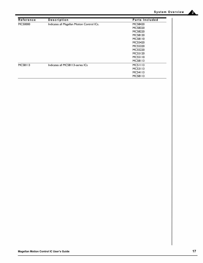
2 . 5 P r o d u c t P / N R e f e r e n c i n g G u i d e
In this manual, various chapters, sections, or paragraphs give descriptions such as “MC55000 only.” The following table indicates the specific products that are referred to by each such reference:
M o t o r Ty p e D e s c r i p t i o n A p p l i c a b l e C h a p t e r s
DC brush Servo motors with internal mechanical commutation, or connected to a commutating amplifier.
1–12, 15, 16
Brushless DC (2 phase, 3 phase)
Servo motors requiring external electrical commutation. 1–13, 15, 16
Microstepping motor Step motor with microstepping drive. 1–4, 6–12, 14-16Pulse & direction step motor
Step motor with pulse & direction drive. 1–4, 6–12, 14, 16
M o t o r Ty p e D e s c r i p t i o n A p p l i c a b l e C h a p t e r s
DC brush Servo motors with internal mechanical commutation. 1–12, 15Brushless DC 3-phase brushless DC servo motors. 1–13, 15Step motor 2-phase step motor. 1–12, 14, 15
R e f e r e n c e D e s c r i p t i o n P a r ts I n c l u d e d
MC58000 Indicates all MC58000 series Magellan Motion Control ICs. MC58420MC58320MC58220MC58120MC58110MC58113MC51113MC53113MC54113
MC55000 Indicates all MC55000 series Magellan Motion Control ICs. MC55420MC55320MC55220MC55120MC55110
16 Magellan Motion Control IC User’s Guide
S y s t e m O v e r v i e w 2
MC50000 Indicates all Magellan Motion Control ICs. MC58420MC58320MC58220MC58120MC58110MC55420MC55320MC55220MC55120MC55110MC58113
MC58113 Indicates all MC58113-series ICs MC51113MC53113MC54113MC58113
R e f e r e n c e D e s c r i p t i o n P a r ts I n c l u d e d
Magellan Motion Control IC User’s Guide 17

S y s t e m O v e r v i e w2
This page intentionally left blank.
18 Magellan Motion Control IC User’s Guide

3
3 . C o n t r o l M o d u l e sIn This ChapterControl Flow OverviewEnabling and Disabling Control ModulesReset CommandSetting the Cycle TimeThe Time RegisterGetVersion Command
3 . 1 C o n t r o l F l o w O v e r v i e w
Figure 3-1 provides a control flow overview for the Magellan Motion Control IC. It shows how a final motor command is generated, starting with the profile generator and ending with the motor output module that generates amplifier-compatible output signals. Only IONs, MC58113-series ICs, and Atlas-connected axes support the current loop/FOC module.
Depending on the type of product and motor, some modules may not be used. For example, step motors do not use a position PID loop. In addition, depending on the nature of the control problem, some modules may be disabled by the user to tailor the control for their specific application.
If Atlas Digital Amplifiers are utilized, then the overall control flow is modified in that the actual current loop and related drive-specific functions are located in the Atlas unit, however the Magellan IC seamlessly integrates the combined
Figure 3-1: Magellan Control Flow Overview
PositionLoop
TrajectoryGenerator
MotorOutput
Commutation/Phasing
CurrentLoop/ FOC
MotorCommand
Phase Command
PWMor DAC
output to amplifier
Position Encoder
Current Feedback
Hall Sensors
CommandedPosition,Velocity,
Acceleration
Magellan Motion Control IC User’s Guide 19

C o n t r o l M o d u l e s3
Magellan/Atlas system into one control structure which is accessed via the Magellan IC. Figure 3-2 shows the overall control flow when an Atlas amplifier is connected.
In the ION module, a single, special ION-specific Magellan IC similar to the MC58113 provides all Magellan functions including current control and drive related functions.
Each of the major blocks within the control flow diagram is referred to as a module. The following table provides a brief description of each module.
Each of these modules are described in detail in subsequent chapters. Beyond the functions provided by these major control modules, Magellan also provides numerous additional capabilities such as breakpoints, trace, and PLC-style
Current Loop, FOC, and Current Feedback are available only when using an ION Drive, with the MC58113-series ICs, and with Atlas-connected axes.
M o d u l e N a m e F u n c t i o n
Trajectory Generator This module accepts user-specified parameters and generates a trajectory.Position Loop This module is used with servo motors only. It inputs the commanded position (the
instantaneous desired axis position) and the actual position (the motor position mea-sured by an encoder), and passes the resultant position error (the difference between the commanded and the actual position) through a PID filter along with dual biquad filters to generate a motor command.
Commutation/Phasing This module is used with multi-phase motors such as brushless DC motors or micro-stepping step motors, and generates desired torque signals for each phase of the motor.
Current Loop/FOC This module is used with ION drives, MC58113-series ICs, and Atlas-connected axes. It inputs the desired torque for each motor phase along with the actual measured current through each phase, and passes the resultant difference through a PI filter to generate a motor command.
Motor Output This module inputs the desired motor phase command and generates the appropriate signals for the selected output format.
PositionLoop
TrajectoryGenerator
MotorOutput
Commutation/Phasing
CurrentLoop/ FOC
MotorCommand To Motor
Position Encoder
Current Feedback
Hall Sensors
CommandedPosition,Velocity,
Acceleration
Atlas® Digital AmplifierFigure 3-2: Magellan/Atlas Control Flow Overview
20 Magellan Motion Control IC User’s Guide
C o n t r o l M o d u l e s 3
signal control. These features are common to all motor types and motion control ICs, and are also described in detail in subsequent chapters.
3 . 2 E n a b l i n g a n d D i s a b l i n g C o n t r o l M o d u l e s
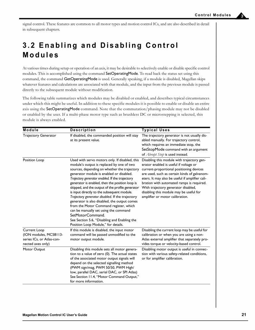
At various times during setup or operation of an axis, it may be desirable to selectively enable or disable specific control modules. This is accomplished using the command SetOperatingMode. To read back the status set using this command, the command GetOperatingMode is used. Generally speaking, if a module is disabled, Magellan skips whatever features and calculations are associated with that module, and the input from the previous module is passed directly to the subsequent module without modification.
The following table summarizes which modules may be disabled or enabled, and describes typical circumstances under which this might be useful. In addition to these specific modules it is possible to enable or disable an entire axis using the SetOperatingMode command. Note that the commutation/phasing module may not be disabled or enabled by the user. If a multi-phase motor type such as brushless DC or microstepping is selected, this module is always enabled.
M o d u l e D e s c r i p t i o n Ty p i c a l U s e s
Trajectory Generator If disabled, the commanded position will stay at its present value.
The trajectory generator is not usually dis-abled manually. For trajectory control, which requires an immediate stop, the SetStopMode command with an argument of Abrupt Stop is used instead.
Position Loop Used with servo motors only. If disabled, this module’s output is replaced by one of two sources, depending on whether the trajectory generator module is enabled or disabled. Trajectory generator enabled. If the trajectory generator is enabled, then the position loop is skipped, and the output of the profile generator is input directly to the subsequent module. Trajectory generator disabled. If the trajectory generator is also disabled, the output comes from the Motor Command register, which can be manually set using the command SetMotorCommand. See Section 5.6, “Disabling and Enabling the Position Loop Module,” for details.
Disabling this module with trajectory gen-erator enabled is useful if voltage or current-proportional positioning devices are used, such as certain kinds of galvanom-eters. It may also be useful if amplifier cali-bration with automated ramps is required. With trajectory generator disabled, disabling this module may be useful for amplifier or motor calibration.
Current Loop (ION modules, MC58113-series ICs, or Atlas-con-nected axes only)
If this module is disabled, the input motor command will be passed unmodified to the motor output module.
Disabling the current loop may be useful for calibration or when you are using a non-Atlas external amplifier that separately pro-vides torque or velocity-based control.
Motor Output Disabling this module sets all motor genera-tion to a value of zero (0). The actual states of the associated motor output signals will depend on the selected signalling method (PWM sign/mag, PWM 50/50, PWM High/low, parallel DAC, serial DAC, or SPI Atlas) See Section 11.4, “Motor Command Output,” for more information.
Disabling motor output is useful in connec-tion with various safety-related conditions, or for amplifier calibration.
Magellan Motion Control IC User’s Guide 21
C o n t r o l M o d u l e s3
In addition to manually disabling modules, there are a number of circumstances where modules may be automatically disabled due to event-related issues, or breakpoints. See Section 8.1, “SetEventAction Processing,” and Section 6.2, “Breakpoints,” for more details.
GetOperatingMode returns the value set using the command SetOperatingMode, which sets the desired operating mode under normal operational circumstances. However this may differ from the actual operating mode for the reasons mentioned above. To determine the actual current status of the operating mode word use the command GetActiveOperatingMode.
3 . 3 R e s e t C o m m a n d
In addition to enabling and disabling control modules, it is possible to entirely reset the motion control IC using the Reset command. This command will bring all registers to their default values and reinitialize all motion control functions. See the Magellan Motion Control IC Programmer’s Command Reference for details on the default values of various Magellan registers.
For MC50000 products a Reset command will have an equivalent effect as toggling the motion control IC’s Reset hardware signal. Also, in addition to manual resets or signal-based resets, a reset operation automatically occurs during motion control ICs powerup. See the Magellan Motion Control IC Electrical Specifications for details.
Due to the large number of operations required to complete a reset operation, Reset commands generally take substantially longer to process than standard Magellan commands. See the Magellan Motion Control IC Electrical Specifications or ION Digital Drive User’s Manual for details.
Note that in normal operation resets are not required. They are generally used during development or debugging to bring the system to a known initial state.
3 . 4 S e t t i n g t h e C y c l e T i m e
The motion control IC calculates all trajectory and servo information on a fixed, regular interval. This interval is known as the cycle time. For each enabled axis of the motion control IC, there is a required “time slice” of either 51.2 (MC50000) or 102.4 (ION) microseconds. In addition, for some motion control ICs there may be added overhead associated with the trace capture facility, and some internal overhead for multi-axis configurations. The minimum cycle times for various configurations of the Magellan Motion Control IC are provided in the following tables.
Throughout this user’s guide various command mnemonics will be shown to clarify motion process or command usage or provide specific examples. See the Magellan Motion Control IC Programmer’s Command Reference for more information on host commands, nomenclature, and syntax.
Executing a Reset command will result in the motor command for all axes being set to zero (0), and all motion control IC activity restarting from a default condition. It is the responsibility of the user to determine whether sending a Reset command is safe for a given operational condition.
22 Magellan Motion Control IC User’s Guide

C o n t r o l M o d u l e s 3
MC50000 Except MC58113-Series
ION & MC58113-Series
The minimum cycle time for ION and the MC58113 does not depend on whether trace has been selected, or any other factors. The following table summarizes this:
The cycle rate determines the trajectory update rate for all motor types, as well as the servo loop calculation rate. It does not necessarily determine the commutation rate, the PWM rate, or the current loop rate.
An enabled axis receives its cycle time slice whether or not it is in motion, and whether or not all the modules are enabled. For multi-axis motion control ICs, if cycle time is critical, it is possible to reclaim that time slice by disabling an unused axis, and then resetting the loop rate with the instructions SetOperatingMode and SetSampleTime.
For example, using an MC55240, four axes are available. If only three of the axes will be used in a specific application, then the unused axis may be disabled using the command SetOperatingMode and a new, lower sample time may be set using the SetSampleTime command. This would improve the cycle frequency from 3.90 kHz to 4.88 kHz.
SetSampleTime may also be used to increase the cycle time to a value greater than the allowed minimum when required.
3 . 5 T h e T i m e R e g i s t e r
Magellan processors keep a 32-bit register that holds the current motion control IC time, measured as the number of cycles executed since powerup or reset. This continuously changing value can be read using the command GetTime.
The register has two primary purposes. It can be used as a comparison value for time-based breakpoints (See Section 6.2, “Breakpoints,” for details). In addition, it can be a useful way of keeping track of actual time elapsed by manually querying the time.
The Time register increases by a value of 1 for each cycle that the motion control IC executes until it reaches its largest possible value of FFFF FFFFh or 4,294,967,295 dec, at which point it wraps back to zero (0). The point at which the time wrap will occur depends on the cycle time set for the motion control IC. For example, for a 4-axis MC58000 with
# E n a b l e d A x e s
M i n i m u m C y c l e T i m e
C y c l e T i m e w / Tr a c e C a p t u r e
Ti m e p e r A x i s
Ma x i mu m C y c l e F r e q u e n c y
1 (ION) 102.4 us 102.4 us 102.4 us 9.76 kHz1 (Magellan
Single-axis)51.2 µs 102.4 µs 51.2 µs 19.53 KHz (9.76 w/
trace capture)1 (Magellan
Multi-axis)102.4µs 102.4 µs 102.4 µs 9.76 kHz
2 (Magellan) 153.6 µs 153.6 µs 76.8 µs 6.51 KHz3 (Magellan) 204.8 µs 204.8 µs 68.3 µs 4.88 KHz4 (Magellan) 256 µs 256 µs 64 µs 3.91 KHz
I O N Mi n i m u m C y c l e T i m e M a x i m u m C y c l e F r e q u e n c y
ION 102.4 µs 9.76 KHzMC58113 51.2 µs 19.53 KHz
SetSampleTime cannot be used to set a sample time lower than the required minimum cycle time for the current configuration. Attempting to do so will set the required minimum as the sample time.
Magellan Motion Control IC User’s Guide 23

C o n t r o l M o d u l e s3
the default cycle time of 256 uSec, wrap will occur at 256 uSec * 4,294,967,295 = ~12.7 days. All motion control IC operations will continue normally, although if a time breakpoint has been set, care should be taken to correctly calculate the comparison time including any potential wrap.
3 . 6 G e t Ve r s i o n C o m m a n d
All Magellan Motion Control ICs can be queried to provide a unique code that indicates the product type and (if applicable) version code. To retrieve this information use the command GetVersion. For a detailed description of the information provided, see the Magellan Motion Control IC Programmer’s Command Reference.
24 Magellan Motion Control IC User’s Guide

4
4 . Tr a j e c t o r y G e n e r a t i o nIn This ChapterTrajectories, Profiles, and ParametersTrapezoidal Point-to-Point Profile S-curve Point-to-Point Profile Velocity-Contouring Profile Electronic Gear Profile The SetStopMode Command Disabling and Enabling the Trajectory Generator Module
4 . 1 Tr a j e c t o r i e s , P r o f i l e s , a n d P a r a m e t e r s
The trajectory generator performs calculations to determine the instantaneous position, velocity, and acceleration of each axis at any given moment. These values are called the commanded values. During a motion profile, some or all of these parameters will continuously change. Once the move is complete, these parameters will remain at the same value until a new move begins.
To query the instantaneous commanded profile values, use the commands GetCommandedPosition, GetCommandedVelocity, and GetCommandedAcceleration.
The specific profile created by the Magellan Motion Control IC depends on several factors, including the presently selected profile mode, the presently selected profile parameters, and other system conditions such as whether a motion stop has been requested. Four trajectory profile modes are supported: S-curve point-to-point, trapezoidal point-to-point, velocity contouring, and electronic gearing. The operation of these profile modes will be explained in detail in subsequent sections. The command used to select the profile mode is SetProfileMode. The command GetProfileMode retrieves the programmed profile mode.
The profile mode may be programmed independently for each axis. For example, axis #1 may be in trapezoidal mode, while axis #2 is in S-curve point-to-point mode.
Magellan Motion Control ICs can switch from one profile to another while an axis is in motion, with only one exception: when switching to the S-curve point-to-point profile from any other profile, the axis must be at rest.
4 . 1 . 1 Tr a j e c t o r y P a r a m e t e r R e p r e s e n ta t i o n
The Magellan Motion Control IC sends and receives trajectory parameters using a fixed-point representation. In other words, a fixed number of bits is used to represent the integer portion of a real number, and a fixed number of bits is used to represent the fractional component of a real number. The motion control IC uses the following three formats.
Magellan Motion Control IC User’s Guide 25
T r a j e c t o r y G e n e r a t i o n4
4 . 2 Tr a p e z o i d a l P o i n t - t o - P o i n t P r o f i l e
The following table summarizes the host-specified profile parameters for the trapezoidal point-to-point profile mode.
The host instructions SetPosition, SetStartVelocity, SetVelocity, SetAcceleration, and SetDeceleration load these values. The commands GetPosition, GetStartVelocity, GetVelocity, GetAcceleration, and GetDeceleration retrieve the programmed values.
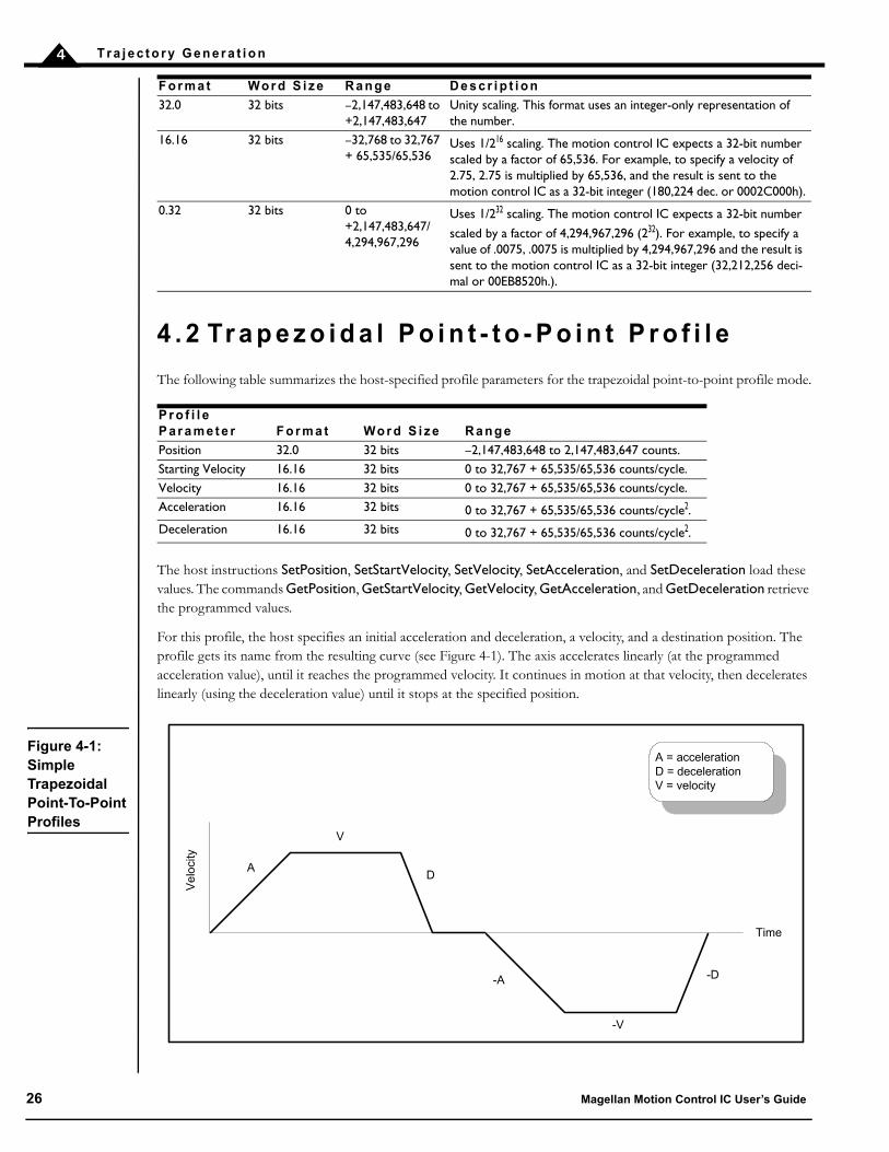
For this profile, the host specifies an initial acceleration and deceleration, a velocity, and a destination position. The profile gets its name from the resulting curve (see Figure 4-1). The axis accelerates linearly (at the programmed acceleration value), until it reaches the programmed velocity. It continues in motion at that velocity, then decelerates linearly (using the deceleration value) until it stops at the specified position.
F o r m a t Wo r d S i z e R a n g e D e s c r i p t i o n
32.0 32 bits –2,147,483,648 to +2,147,483,647
Unity scaling. This format uses an integer-only representation of the number.
16.16 32 bits –32,768 to 32,767 + 65,535/65,536
Uses 1/216 scaling. The motion control IC expects a 32-bit number scaled by a factor of 65,536. For example, to specify a velocity of 2.75, 2.75 is multiplied by 65,536, and the result is sent to the motion control IC as a 32-bit integer (180,224 dec. or 0002C000h).
0.32 32 bits 0 to +2,147,483,647/4,294,967,296
Uses 1/232 scaling. The motion control IC expects a 32-bit number
scaled by a factor of 4,294,967,296 (232). For example, to specify a value of .0075, .0075 is multiplied by 4,294,967,296 and the result is sent to the motion control IC as a 32-bit integer (32,212,256 deci-mal or 00EB8520h.).
P r o f i l e P a r a m e t e r F o r m a t Wo r d S i z e R a n g e
Position 32.0 32 bits –2,147,483,648 to 2,147,483,647 counts.Starting Velocity 16.16 32 bits 0 to 32,767 + 65,535/65,536 counts/cycle.Velocity 16.16 32 bits 0 to 32,767 + 65,535/65,536 counts/cycle.Acceleration 16.16 32 bits 0 to 32,767 + 65,535/65,536 counts/cycle2.Deceleration 16.16 32 bits 0 to 32,767 + 65,535/65,536 counts/cycle2.
Figure 4-1: Simple Trapezoidal Point-To-Point Profiles
Time
Ve
loci
ty
A = accelerationD = decelerationV = velocity
A
V
D
-A
-V
-D
26 Magellan Motion Control IC User’s Guide

T r a j e c t o r y G e n e r a t i o n 4
Figure 4-1 illustrates a trapezoidal profile with the starting velocity set at the default value of zero (0). When whole-stepping a step motor, it is sometimes desirable to define a non-zero starting velocity from which the motor will instantaneously begin motion. This is to avoid passing through the resonant frequency of a step motor. In the deceleration phase of the profile, rather than continuously decelerate to a velocity of zero (0), the velocity will transition from the start velocity to zero (0) velocity with no deceleration phase in between. Figure 4-2 shows a typical trapezoidal profile with non-zero starting velocity.
Note that a programmable starting velocity is supported in Trapezoidal and Velocity Contouring profile modes only. It is not supported in Electronic Gear or S-curve profile modes.
If deceleration must begin before the axis reaches the programmed velocity, the profile will have no constant velocity portion, and the trapezoid becomes a triangle, as shown in Figure 4-3.
The slopes of the acceleration and deceleration segments may be symmetric (if acceleration is equal to deceleration), or asymmetric (if acceleration is not equal to deceleration).
The acceleration parameter is always used at the start of the move. Thereafter, the acceleration value will be used when the absolute value of velocity is increasing, and deceleration will be used when the absolute value of velocity is
Figure 4-2: Trapezoidal Profile With Non-Zero Starting Velocity
Time
Ve
loci
ty
A = accelerationD = decelerationV = velocity
A
V
D
-A
-V
-D
Starting Velocity
Starting Velocity
Figure 4-3: Simple Trapezoidal Point-To-Point Profile
Time
Ve
loci
ty
A = accelerationD = deceleration
A D
Magellan Motion Control IC User’s Guide 27
T r a j e c t o r y G e n e r a t i o n4
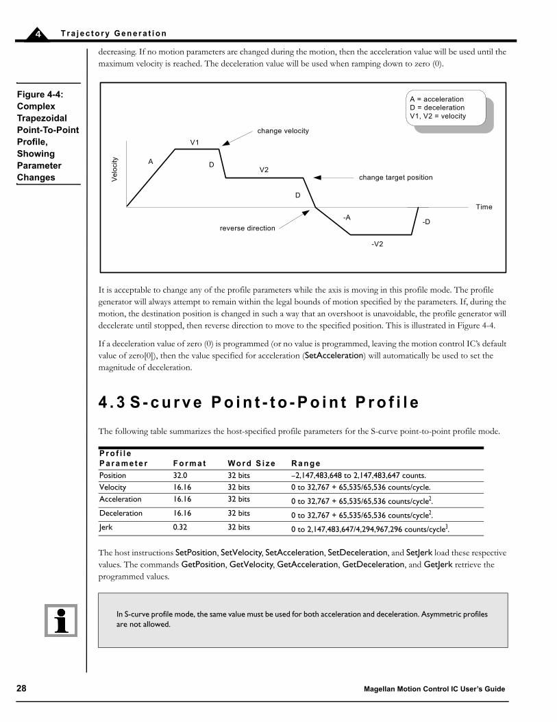
decreasing. If no motion parameters are changed during the motion, then the acceleration value will be used until the maximum velocity is reached. The deceleration value will be used when ramping down to zero (0).
It is acceptable to change any of the profile parameters while the axis is moving in this profile mode. The profile generator will always attempt to remain within the legal bounds of motion specified by the parameters. If, during the motion, the destination position is changed in such a way that an overshoot is unavoidable, the profile generator will decelerate until stopped, then reverse direction to move to the specified position. This is illustrated in Figure 4-4.
If a deceleration value of zero (0) is programmed (or no value is programmed, leaving the motion control IC’s default value of zero[0]), then the value specified for acceleration (SetAcceleration) will automatically be used to set the magnitude of deceleration.
4 . 3 S - c u r v e P o i n t - t o - P o i n t P r o f i l e
The following table summarizes the host-specified profile parameters for the S-curve point-to-point profile mode.
The host instructions SetPosition, SetVelocity, SetAcceleration, SetDeceleration, and SetJerk load these respective values. The commands GetPosition, GetVelocity, GetAcceleration, GetDeceleration, and GetJerk retrieve the programmed values.
P r o f i l e P a r a m e t e r F o r m a t Wo r d S i z e R a n g e
Position 32.0 32 bits –2,147,483,648 to 2,147,483,647 counts.Velocity 16.16 32 bits 0 to 32,767 + 65,535/65,536 counts/cycle.Acceleration 16.16 32 bits 0 to 32,767 + 65,535/65,536 counts/cycle2.Deceleration 16.16 32 bits 0 to 32,767 + 65,535/65,536 counts/cycle2.Jerk 0.32 32 bits 0 to 2,147,483,647/4,294,967,296 counts/cycle3.
In S-curve profile mode, the same value must be used for both acceleration and deceleration. Asymmetric profiles are not allowed.
Time
Ve
loci
ty
A = accelerationD = decelerationV1, V2 = velocity
A
V1
DV2
-V2
D
-A-D
change velocity
change target position
reverse direction
Figure 4-4: Complex Trapezoidal Point-To-Point Profile, Showing Parameter Changes
28 Magellan Motion Control IC User’s Guide

T r a j e c t o r y G e n e r a t i o n 4
The S-curve point-to-point profile adds a limit to the rate of change of acceleration to the basic trapezoidal curve. A new parameter (jerk) is added which specifies the maximum change in acceleration in a single cycle.
In this profile mode, the acceleration gradually increases from 0 to the programmed acceleration value, then the acceleration decreases at the same rate until it reaches 0 again at the programmed velocity. The same sequence in reverse brings the axis to a stop at the programmed destination position.
Figure 4-5 shows a typical S-curve profile. In Segment I, the S-curve profile drives the axis at the specified jerk (J) until the maximum acceleration (A) is reached. The axis continues to accelerate linearly (jerk = 0) through Segment II. The profile then applies the negative value of the jerk to reduce acceleration to 0 during Segment III. The axis is now at maximum velocity (V), at which it continues through Segment IV. The profile will then decelerate in a manner similar to the acceleration stage, using the jerk value first to reach the maximum deceleration (D) and then to bring the axis to a halt at the destination.
An S-curve profile might not contain all of the segments shown in Figure 4-5. For example, if the maximum acceleration cannot be reached before the “halfway” point to or from the velocity, the profile would not contain a Segment II or a Segment VI. Such a profile is shown in Figure 4-6.
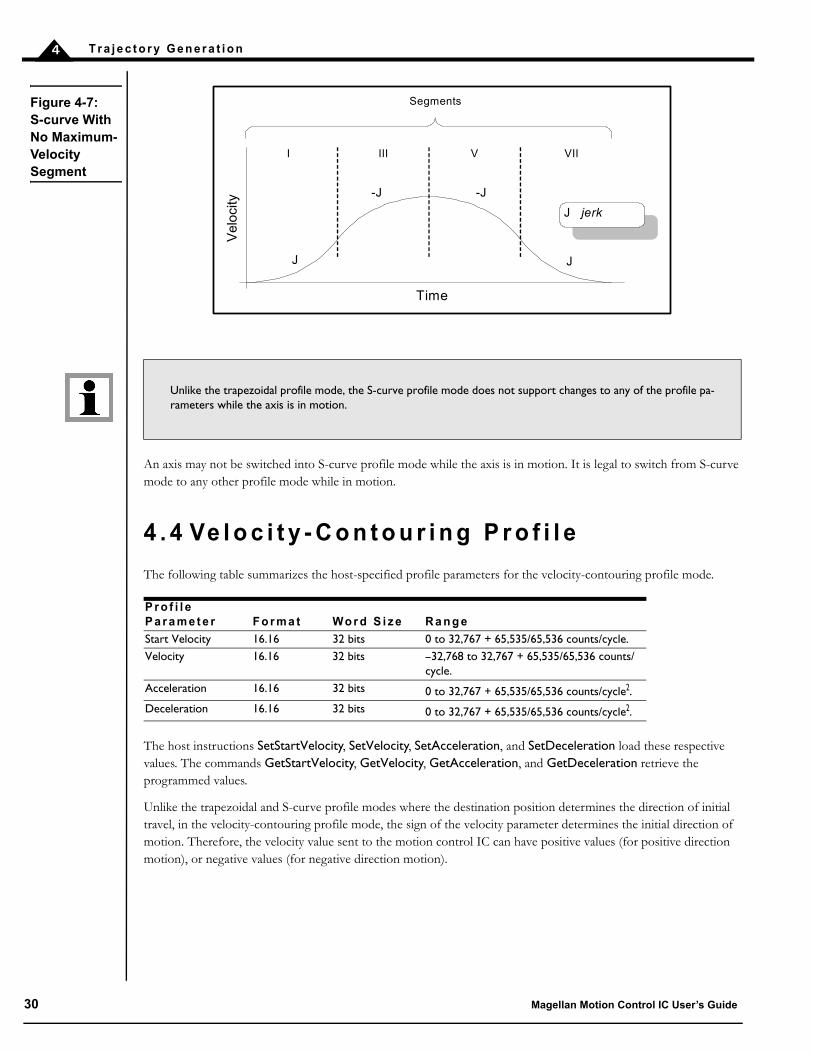
Similarly, if the position is specified such that velocity is not reached, there will be no Segment IV, as shown in Figure 4-7. There may also be no Segment II or Segment VI depending on where the profile is truncated.
A accelerationD decelerationV velocityJ jerk
Time
I II III IV V
J
-J
J
A D
V
Segments
-J
Vel
ocity
VI VII
Figure 4-5: Typical S-curve Point-To-PointProfile
Figure 4-6: S-curve That Does Not Reach Maximum Acceleration
V velocityJ jerk
Time
I III
J
-J
J
V
Segments
-J
Vel
ocity
VIIVIV
Magellan Motion Control IC User’s Guide 29
T r a j e c t o r y G e n e r a t i o n4
An axis may not be switched into S-curve profile mode while the axis is in motion. It is legal to switch from S-curve mode to any other profile mode while in motion.
4 . 4 Ve l o c i t y - C o n t o u r i n g P r o f i l e
The following table summarizes the host-specified profile parameters for the velocity-contouring profile mode.
The host instructions SetStartVelocity, SetVelocity, SetAcceleration, and SetDeceleration load these respective values. The commands GetStartVelocity, GetVelocity, GetAcceleration, and GetDeceleration retrieve the programmed values.
Unlike the trapezoidal and S-curve profile modes where the destination position determines the direction of initial travel, in the velocity-contouring profile mode, the sign of the velocity parameter determines the initial direction of motion. Therefore, the velocity value sent to the motion control IC can have positive values (for positive direction motion), or negative values (for negative direction motion).
Unlike the trapezoidal profile mode, the S-curve profile mode does not support changes to any of the profile pa-rameters while the axis is in motion.
P r o f i l e P a r a m e t e r F o r m a t Wo r d S i z e R a n g e
Start Velocity 16.16 32 bits 0 to 32,767 + 65,535/65,536 counts/cycle.Velocity 16.16 32 bits –32,768 to 32,767 + 65,535/65,536 counts/
cycle.Acceleration 16.16 32 bits 0 to 32,767 + 65,535/65,536 counts/cycle2.Deceleration 16.16 32 bits 0 to 32,767 + 65,535/65,536 counts/cycle2.
Figure 4-7: S-curve With No Maximum-Velocity Segment
J jerk
Time
I III
J
-J
J
Segments
-J
Vel
oci
ty
VIIV
30 Magellan Motion Control IC User’s Guide
T r a j e c t o r y G e n e r a t i o n 4
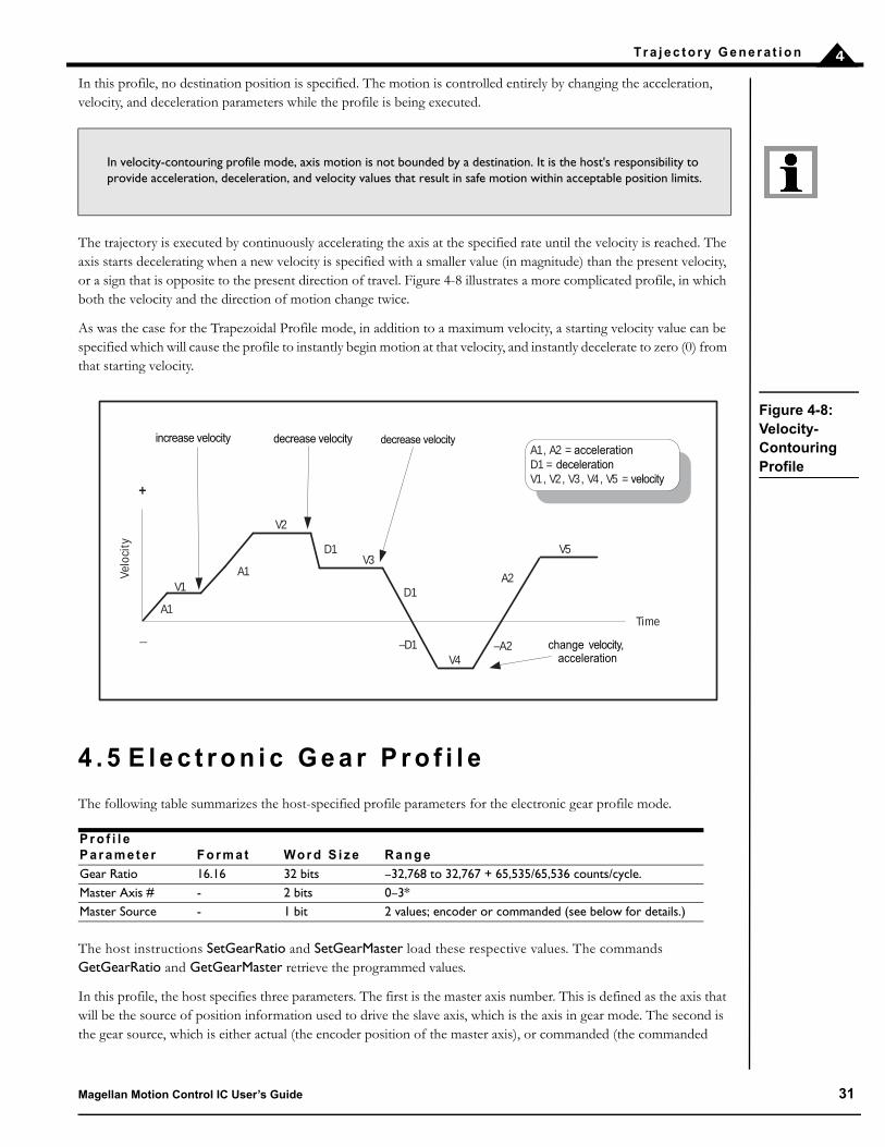
In this profile, no destination position is specified. The motion is controlled entirely by changing the acceleration, velocity, and deceleration parameters while the profile is being executed.
The trajectory is executed by continuously accelerating the axis at the specified rate until the velocity is reached. The axis starts decelerating when a new velocity is specified with a smaller value (in magnitude) than the present velocity, or a sign that is opposite to the present direction of travel. Figure 4-8 illustrates a more complicated profile, in which both the velocity and the direction of motion change twice.
As was the case for the Trapezoidal Profile mode, in addition to a maximum velocity, a starting velocity value can be specified which will cause the profile to instantly begin motion at that velocity, and instantly decelerate to zero (0) from that starting velocity.
4 . 5 E l e c t r o n i c G e a r P r o f i l e
The following table summarizes the host-specified profile parameters for the electronic gear profile mode.
The host instructions SetGearRatio and SetGearMaster load these respective values. The commands GetGearRatio and GetGearMaster retrieve the programmed values.
In this profile, the host specifies three parameters. The first is the master axis number. This is defined as the axis that will be the source of position information used to drive the slave axis, which is the axis in gear mode. The second is the gear source, which is either actual (the encoder position of the master axis), or commanded (the commanded
In velocity-contouring profile mode, axis motion is not bounded by a destination. It is the host's responsibility to provide acceleration, deceleration, and velocity values that result in safe motion within acceptable position limits.
P r o f i l e P a r a m e t e r F o r m a t Wo r d S i z e R a n g e
Gear Ratio 16.16 32 bits –32,768 to 32,767 + 65,535/65,536 counts/cycle.Master Axis # - 2 bits 0–3*Master Source - 1 bit 2 values; encoder or commanded (see below for details.)
Time
Velo
city
change velocity,acceleration
increase velocity
_
+
A1, A2 = accelerationD1 = decelerationV1 , V2 , V3 , V4 , V5 = velocity
A1
A1V1
V2
V3D1
D1
–D1V4
–A2
A2
V5
decrease velocity decrease velocity
Figure 4-8: Velocity-Contouring Profile
Magellan Motion Control IC User’s Guide 31

T r a j e c t o r y G e n e r a t i o n4
position of the master axis). The third is the gear ratio, which specifies the direction and ratio of master gear counts to slave counts.
Normally, the slave axis is set to an axis different than the master axis. One allowed exception is when step motors are being used. In this case, the master axis may be set to the same axis as the slave, as long as the gear source is set to encoder. For servo motors, the master axis must be a different axis than the slave axis.
Note that for ION and the MC58113, the “auxiliary axis” is treated as the second axis.
Figure 4-9 shows the arrangement of encoders and motor drives in a typical electronic gearing application.
A positive gear ratio value means that during an increase in either the master axis actual or commanded position, the slave commanded position will also increase. A negative gear ratio value has the opposite effect: increasing master position will result in decreasing slave axis commanded position.
For example, assume the slave axis is axis #1 and the master axis is set to axis #4. Also, assume the source will be actual with a gear ratio of –1/2. Then for each positive encoder count of axis 4, axis 1 commanded position will decrease in value by 1/2 count, and for each negative encoder count of axis 4, axis 1 commanded position will increase in value by 1/2 count.
The electronic gear profile requires two axes to be enabled. The single-axis motion control ICs do not support electronic gearing.
If the master axis source is set to actual, then this axis need not have a physical motor attached to it. Frequently, it is used only for its encoder input, for example, from a directly driven (open-loop) motor, or a manual control. It is possible to drive a motor on the master axis by enabling the axis and applying a profile mode other than electronic gear to the axis. The effect of this arrangement is that both master and slave can be driven by the same profile, even though the slave can drive at a different ratio and in a different direction if desired. The master axis will operate the same, whether or not it happens to be the master for some other geared axis. The “optional” components shown in Figure 4-9 illustrate this arrangement. Such a configuration can be used to perform useful functions such as linear interpolation of two axes.
Magellan Motion Processor
Slave encoder
Motor
Amplifier
Amplifier
Motor
Master encoder
optional
Figure 4-9: Electronic Gear Profile
32 Magellan Motion Control IC User’s Guide

T r a j e c t o r y G e n e r a t i o n 4
Note that unlike the trapezoidal, S-curve, and velocity contouring profile modes, electronic gearing profile mode does not have an explicit sense of whether motion is “completed” or not. Therefore, the “motion complete” bit of the Event Status register, as well as the “in-motion” bit of the Activity Status register, do not function when in this profile mode.
4 . 6 T h e S e t S t o p M o d e C o m m a n d
Normally, each of the trajectory profile modes will execute the specified trajectory, within the specified parameter limits, until the profile conditions are satisfied. For example, for the point-to-point profile modes this means that the profile will move the axis until the final destination position has been reached, at which point the axis will have a velocity of zero (0).
In some cases, it may be necessary to halt the trajectory manually, either for safety reasons, or simply to achieve a specific profile. This may be accomplished using one of two methods: Abrupt Stop or Smooth Stop.
To perform a stop, the command SetStopMode is used. To retrieve the current stop mode, the command GetStopMode is used. Using the SetStopMode command to set the mode to Abrupt Stop instantaneously stops the profile by setting the target velocity of the designated axis to zero (0). This is, in effect, an emergency stop with instantaneous deceleration.
Setting the stop mode to Smooth Stop brings the designated axis to a controlled stop, using the current deceleration parameter to reduce the velocity to zero (0).
In either mode, the target velocity is set to zero (0) after the SetStopMode command is executed. Before any other motion can take place, the velocity must then be reset using the SetVelocity command.
Abrupt Stop functions in all profiles. Smooth Stop functions in all profiles except electronic gearing.
4 . 7 D i s a b l i n g a n d E n a b l i n g t h e Tr a j e c t o r y G e n e r a t o r M o d u l e
There are a number of reasons why it might be desirable to disable the trajectory generator module. See Section 3.1, “Control Flow Overview,” for more information on the functions of the Trajectory Generator. In addition, there are event-related actions that may result in this module being disabled. See Section 8.1, “SetEventAction Processing,” for details.
The gear ratio parameter may be changed while the axis is in motion, but care should be taken to select ratios so that safe motion is maintained.
For selected ION modules and the MC58113, electronic gear can also be used with a pulse & direction input signal for the auxiliary encoder axis. In this mode, all the standard electronic gear commands are used, with one master axis input ‘pulse’ being equivelent to one master axis input encoder ‘tick’. To operate in this mode the master axis number is set to #2 (auxiliary axis) and the encoder source is set to pulse & direction. See section 10.0 for more information on the SetEncoderSource command.
Abrupt Stop must be used with care. Sudden deceleration from a high velocity can damage equipment or cause injury.
Magellan Motion Control IC User’s Guide 33

T r a j e c t o r y G e n e r a t i o n4
If the trajectory generator module is disabled, the current commanded position will remain at its present value. All profile and other commands will be ignored. In addition, if the position loop is enabled, at the time the trajectory generator module is disabled, the position error will be set to 0 (equivalent to ClearPositionError command).
A previously disabled trajectory generator module may be re-enabled in a number of ways. If the module was disabled using the SetOperatingMode command, then another SetOperatingMode command may be issued. If the trajectory generator module was disabled as part of an automatic event-related action (see Section 8.1, “SetEventAction Processing,” for more information) then the command RestoreOperatingMode is used.
3 4 M a g e l l a n M o t i o n Control IC U s e r ’ s G u i d e

5
5 . P o s i t i o n L o o pIn This ChapterOverviewDual Encoder SupportBiquad Output FiltersOutput LimitMotor Bias Disabling and Enabling the Position Loop Module
5 . 1 O v e r v i e w
For Magellan motion control ICs that provide servo motor support, a position loop is used as part of the basic method of determining the motor command output. The function of the position loop is to match as closely as possible the commanded position, which comes from the trajectory generator, and the actual motor position. To accomplish this, the commanded value is combined with the actual encoder position to create position error, which is then passed through a digital PID-type servo filter. The scaled result of the filter calculation is the motor command, which is then passed to a “downstream” module, either the commutation/phasing module, the current loop/FOC module, or the motor output module, depending on the motor type chosen and Magellan product being used.
The overall position loop is split into two major sections, the PID loop, and the biquad filters. The PID loop generates an initial motor command, while the dual biquad filters can be used to perform various frequency-domain filtering such as notch, lowpass, and bandpass. Once the output of the PID and biquad filters is generated, it can be further limited to a prescribed range, thereby accommodating amplifiers, motors, or physical systems, as shown in Figure 5-1.
Figure 5-1: PID Loop And Biquad Filters
MotorCommand
CommandedPosition
Position Error Biquad
1PID
Filter+-
++
MotorBias
Position Encoder
Biquad2
++
+
MotorLimit
Commanded Velocity
Commanded Acceleration
Magellan Motion Control IC User’s Guide 35

P o s i t i o n L o o p5
To perform position control, all servo applications require that safe and stable PID loop parameters be specified. Use of the dual biquad filters, on the other hand, is optional and will depend on the nature and complexity of the control problem. The more demanding the application, the more likely that the biquads will be useful.
5 . 1 . 1 P I D L o o p
The servo filter used with the Magellan Motion Control ICs is a proportional-integral-derivative (PID) algorithm, with velocity and acceleration feed-forward terms and an output scale factor. An integration limit provides an upper bound for the accumulated error. An optional bias value may be added to the filter calculation to produce the final motor output command. Figure 5-2 provides a control flow overview of the PID loop:
Figure 5-2: Position Loop Flow
biquad filters
Z -1
Z -1
+
-
- +X
X
X
X
÷
X
commanded velocity
output
commanded acceleration
commanded position
encoder feedback
derivative time
integration limit
65,536
X
÷
8
Kaff
Kout
Kp
Kd
Kvff
4
÷
256
X
Ki
-
36 Magellan Motion Control IC User’s Guide
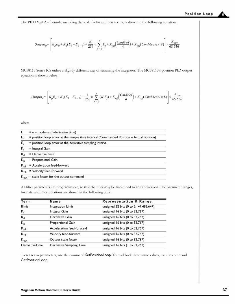
P o s i t i o n L o o p 5
The PID+Vff+Aff formula, including the scale factor and bias terms, is shown in the following equation:
MC58113 Series ICs utilize a slightly different way of summing the integrator. The MC58113's position PID output equation is shown below:
where
All filter parameters are programmable, so that the filter may be fine-tuned to any application. The parameter ranges, formats, and interpretations are shown in the following table.
To set servo parameters, use the command SetPositionLoop. To read back these same values, use the command GetPositionLoop.
k = n – modulus (n/derivative time)En = position loop error at the sample time interval (Commanded Position – Actual Position)
Ek = position loop error at the derivative sampling interval
Ki = Integral Gain
Kd = Derivative Gain
Kp = Proportional Gain
Kaff = Acceleration feed-forward
Kvff = Velocity feed-forward
Kout = scale factor for the output command
Te r m N a m e R e p r e s e n ta t i o n & R a n g e
Ilimit Integration Limit unsigned 32 bits (0 to 2,147,483,647)Ki Integral Gain unsigned 16 bits (0 to 32,767)
Kd Derivative Gain unsigned 16 bits (0 to 32,767)
Kp Proportional Gain unsigned 16 bits (0 to 32,767)
Kaff Acceleration feed-forward unsigned 16 bits (0 to 32,767)
Kvff Velocity feed-forward unsigned 16 bits (0 to 32,767)
Kout Output scale factor unsigned 16 bits (0 to 32,767)
DerivativeTime Derivative Sampling Time unsigned 16 bits (1 to 32,767)
Outputn KpEn Kd Ek Ek 1–– Ki
256--------- Ej
j 0=
n
KvffCmdVel
4--------------------- + Kaff CmdAccel 8 + + +
Kout
65 536------------------=
Outputn KpEn Kd Ek Ek 1–– 1256--------- KiEj
j 0=
n
KvffCmdVel
4--------------------- + Kaff CmdAccel 8 + + +
Kout
65 536------------------=
Magellan Motion Control IC User’s Guide 37

P o s i t i o n L o o p5
5 . 1 . 2 I n t e g r a t i o n L i m i t
The integration limit is used to place a boundary on the absolute value that is contributed to the PID output by the integration term. Its default value after a reset is zero (0), which will result in the output from the integration term of the PID filter evaluating to zero (0). In order to use the Ki value, the integration limit must be programmed with
a value greater than zero (0). For more information on the scaling of the integration limit, refer to the Magellan Programmer’s Command Reference. As for other PID loop parameters, the integration limit can be set using the host instruction SetPositionLoop. It can be read using the command GetPositionLoop.
5 . 1 . 3 O u t p u t S c a l i n g
The Kout parameter can be used to scale down the output of the PID filter by multiplying the filter result by
Kout/65,536. It has the effect of increasing the usable range of Kp. The Kout value is set using the host instruction
SetPositionLoop. It is read by using the command GetPositionLoop.
Unlike the default value of most PID loop parameters, which is zero (0), Kout has a power-up default value of 65,535, or 100%.
5 . 1 . 4 D e r i v a t i v e S a m p l i n g T i m e
Normally, the derivative term of the PID loop is recalculated at every servo cycle. Under some circumstances, however, it may be desirable to reduce the derivative sampling rate to a rate lower than this, to improve system stability, or simplify tuning. This can be accomplished using the command SetPositionLoop, and the value set can be read back using the command GetPositionLoop.
The specified value is the desired number of servo cycles per motion control IC sample time. For example, if the motion control IC’s sample time (set using SetSampleTime command) has been set to 200 uSec (giving an effective sampling time of 204.8 uSec), a value of 1 programmed in the DerivativeTime register will result in a derivative sample time of 204.8 uSec, while a value of 10 will result in a sample time of 2.048 mSec, or once every 10 servo cycles.
Changing the derivative sample time has no effect on the overall motion control IC sample time set using the command SetSampleTime.
The default value for the derivative time is 1, meaning that by default the derivative term is calculated at each servo cycle.
5 . 2 D u a l E n c o d e r S u p p o r t
The multi-axis MC58000 motion control ICs (MC58420, MC58320, MC58220), the ION, and MC58113 support a dual encoder PID configuration, which may be useful for applications where the position of the load is critical, but cannot be deterministically related to the motor position because of backlash or other forms of mechanical compliance. In this configuration, the encoder input for a second axis (other than the one being controlled) is incorporated as the derivative term in the servo loop as shown in Figure 5-3. For the ION and the MC58113, this second axis is known as the auxiliary encoder input.
For axes driving brushless DC motors in dual encoder mode, the auxiliary axis encoder is used for sinusoidal commutation.
38 Magellan Motion Control IC User’s Guide

P o s i t i o n L o o p 5
Figure 5-3 provides an overall connection scheme for axes used in the dual loop configuration.
5 . 2 . 1 D u a l E n c o d e r P I D L o o p A l g o r i t h m
The structure of the servo filter used by the motion control IC in dual-encoder mode is slightly different from that used in single-encoder mode. The dual-encoder algorithm that follows is illustrated in Figure 5-4:
where
E1n = the accumulated error terms from the main encoder
Pn = position of the auxiliary encoder
Ki = Integral Gain
Kd = Derivative Gain
Kp = Proportional Gain
Kaff = Acceleration feed-forward
Kvff = Velocity feed-forward
Kout = scale factor for the output command
Figure 5-3: Magellan Dual-Loop Flow
B iquad 1
B iquad 2
D
P I
Load Encoder
M otor Encoder
M otor C om m and
M otor B ias
C om m andedPosition
C om m anded Velocity
C om m anded Acce leration
+-
+ ++
-+
+
M otor L im it
Outputn KpE1n Kd Pn Pn 1–– – E1jj 0=
n
+Ki
256--------- Kvff
CmdVel4
--------------------- Kaff CmdAccel 8 + +
Kout
65 536------------------=
Magellan Motion Control IC User’s Guide 39

P o s i t i o n L o o p5
5 . 2 . 2 C o n f i g u r i n g D u a l E n c o d e r S u p p o r t
The SetAuxiliaryEncoderSource command is used to enable dual encoder processing for an axis. The AuxiliaryAxis parameter controls which axis’ encoder input will be used to augment the primary (Load) encoder. The mode parameter enables or disables dual loop processing. Section 5.1.1, “PID Loop,” describes how the servo processing loop functions when dual loop is disabled (the default condition).
If the application needs to determine the actual position of the auxiliary encoder, use the GetActualPosition command, and specify the axis of the auxiliary encoder.
For MC50000 products the total number of encoder inputs supported by a given Magellan Motion Control IC is equal to the number of control axes supported. In other words, a four-axis motion control IC has four input encoder channels. Using an encoder channel for dual-loop, therefore, reduces the total number of available control axes by one. ION and the MC58113 is different in that they are a single axis products, but have an additional “auxiliary” encoder input channel.
The auxiliary encoder should always have a resolution which is greater than or equal to the resolution of the main encoder to avoid unstable operation in dual loop mode.
biquad filters
Z -1
Z -1
+
-
÷
- +X
X
X
X
÷
X
commanded velocity
output
commanded acceleration
commanded position
encoder feedback
integration limit
65,536
256
X
÷
8
Kaff
Kout
Kp
Kd
Kvff
4
auxiliaryencoder
X
Ki
-
Figure 5-4: Magellan Dual-Loop Digital Filter
40 Magellan Motion Control IC User’s Guide

P o s i t i o n L o o p 5
5 . 3 B i q u a d O u t p u t F i l t e r s
A biquad is a generic digital filter structure. With the proper coefficients, it can be programmed to be a low-pass filter, high-pass filter, band-pass filter, notch filter, or custom filter. Programs such as Octave (www.octave.org) may be used to find the coefficients.
The Magellan Motion Control IC supports two programmable biquad output filters for each axis. These filters are chained. When both are enabled, the output of Filter1 feeds the input of Filter2. If Filter1 is disabled (the default state), the entire filter chain is bypassed, and the motion control IC output passes unfiltered to the motor.
The output of the filter at time n is determined with the following equation:
where:
The following table shows biquad filter coefficients that are set using the command SetPositionLoop. They can be read back using the command GetPositionLoop. The following table summarizes the representation and range for the settable biquad parameters.
Yn = output of the filter at time n
Xn = input to the filter at time n
K = positive scaling value used to avoid rounding errorsB0 = programmable biquad coefficient
B1 = programmable biquad coefficient
B2 = programmable biquad coefficient
A1 = programmable biquad coefficient
A2 = programmable biquad coefficient
Te r m N a m e R e p r e s e n ta t i o n & R a n g e
K biquad scalar unsigned 16 bits (0 to 32,767)A1 coefficient A1 signed 16 bits (–32,768 to 32,767)
A2 coefficient A2 signed 16 bits (–32,768 to 32,767)
B0 coefficient B0 signed 16 bits (–32,768 to 32,767)
B1 coefficient B1 signed 16 bits (–32,768 to 32,767)
OutputInputX
Z
X
Z
X
Z
X
Z
X
-1
-1-1
-1
+ + + ++
A1
A2B2
B1
B0
X
KScalar
Figure 5-5: Biquad Algorithm Flow
Yn K B0 Xn B1 Xn 1– B2 Xn 2– A1 Yn 1– A2 Yn 2–+++ =
Magellan Motion Control IC User’s Guide 41
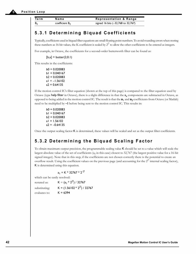
P o s i t i o n L o o p5
5 . 3 . 1 D e t e r m i n i n g B i q u a d C o e f f i c i e n ts
Typically, coefficients used in biquad filter equations are small floating point numbers. To avoid rounding errors when storing these numbers as 16-bit values, the K coefficient is scaled by 227 to allow the other coefficients to be entered as integers.
For example, in Octave, the coefficients for a second-order butterworth filter can be found as:
[b,a] = butter(2,0.1)
This results in the coefficients:
b0 = 0.020083b1 = 0.040167b2 = 0.020083a1 = –1.56102a2 = 0.64135
If the motion control IC’s filter equation (shown at the top of this page) is compared to the filter equation used by Octave (type help filter in Octave), there is a slight difference in that the ax components are subtracted in Octave, as opposed to being added in the motion control IC. The result is that the a1 and a2 coefficients from Octave (or Matlab) need to be multiplied by –1 before being sent to the motion control IC. This results in:
b0 = 0.020083b1 = 0.040167b2 = 0.020083a1 = 1.56102a2 = –0.64135
Once the output scaling factor K is determined, these values will be scaled and set as the output filter coefficients.
5 . 3 . 2 D e t e r m i n i n g t h e B i q u a d S c a l i n g F a c t o r
To obtain maximum output precision, the programmable scaling value K should be set to a value which will scale the largest absolute value of the set of coefficients (a1 in this case) closest to 32,767 (the largest positive value for a 16-bit signed integer). Note that in this step, if the coefficients are not chosen correctly there is the potential to create an overflow result. Using the coefficient values on the previous page (and accounting for the 227 internal scaling factor), K is determined using this equation.
a1 = K * 32767 * 2–27
which can be easily resolved:
restated as: K = (a1 * 227) / 32767
substituting: K = (1.56102 * 227) / 32767
evaluates to: K = 6394
B2 coefficient B2 signed 16 bits (–32,768 to 32,767)Te r m N a m e R e p r e s e n ta t i o n & R a n g e
42 Magellan Motion Control IC User’s Guide
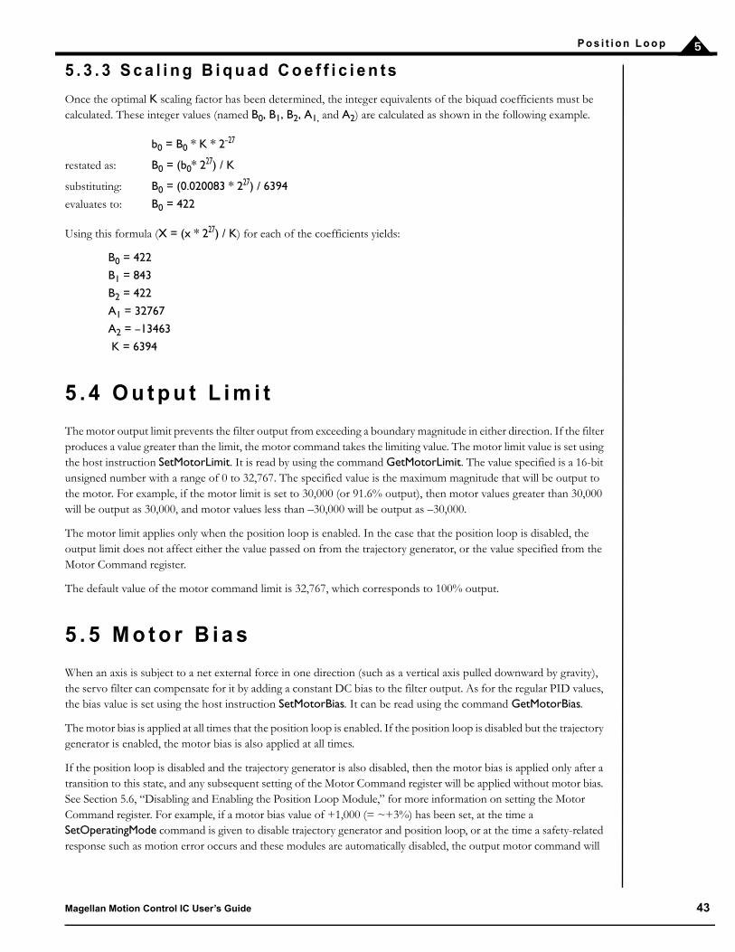
P o s i t i o n L o o p 5
5 . 3 . 3 S c a l i n g B i q u a d C o e f f i c i e n ts
Once the optimal K scaling factor has been determined, the integer equivalents of the biquad coefficients must be calculated. These integer values (named B0, B1, B2, A1, and A2) are calculated as shown in the following example.
b0 = B0 * K * 2–27
restated as: B0 = (b0* 227) / K
substituting: B0 = (0.020083 * 227) / 6394
evaluates to: B0 = 422
Using this formula (X = (x * 227) / K) for each of the coefficients yields:
B0 = 422
B1 = 843
B2 = 422
A1 = 32767
A2 = –13463
K = 6394
5 . 4 O u t p u t L i m i t
The motor output limit prevents the filter output from exceeding a boundary magnitude in either direction. If the filter produces a value greater than the limit, the motor command takes the limiting value. The motor limit value is set using the host instruction SetMotorLimit. It is read by using the command GetMotorLimit. The value specified is a 16-bit unsigned number with a range of 0 to 32,767. The specified value is the maximum magnitude that will be output to the motor. For example, if the motor limit is set to 30,000 (or 91.6% output), then motor values greater than 30,000 will be output as 30,000, and motor values less than –30,000 will be output as –30,000.
The motor limit applies only when the position loop is enabled. In the case that the position loop is disabled, the output limit does not affect either the value passed on from the trajectory generator, or the value specified from the Motor Command register.
The default value of the motor command limit is 32,767, which corresponds to 100% output.
5 . 5 M o t o r B i a s
When an axis is subject to a net external force in one direction (such as a vertical axis pulled downward by gravity), the servo filter can compensate for it by adding a constant DC bias to the filter output. As for the regular PID values, the bias value is set using the host instruction SetMotorBias. It can be read using the command GetMotorBias.
The motor bias is applied at all times that the position loop is enabled. If the position loop is disabled but the trajectory generator is enabled, the motor bias is also applied at all times.
If the position loop is disabled and the trajectory generator is also disabled, then the motor bias is applied only after a transition to this state, and any subsequent setting of the Motor Command register will be applied without motor bias. See Section 5.6, “Disabling and Enabling the Position Loop Module,” for more information on setting the Motor Command register. For example, if a motor bias value of +1,000 (= ~+3%) has been set, at the time a SetOperatingMode command is given to disable trajectory generator and position loop, or at the time a safety-related response such as motion error occurs and these modules are automatically disabled, the output motor command will
Magellan Motion Control IC User’s Guide 43
P o s i t i o n L o o p5
be +1,000. If, in the process of recovering from this condition, a user sets the motor command to +2,000, this value, unaffected by the motor bias, will be output.
The default value of motor bias is zero (0).
5 . 6 D i s a b l i n g a n d E n a b l i n g t h e P o s i t i o n L o o p M o d u l e
There are a number of reasons why it might be desirable to disable the position loop module. See Section 3.1, “Control Flow Overview,” for details. In addition, there are event-related actions that may result in this module being disabled. See Section 8.1, “SetEventAction Processing,” for details.
If the position loop module is disabled, the overall control flow of the motion control IC module will be altered in one of two ways, depending on whether the trajectory generator is enabled or disabled when the position loop module is disabled.
Trajectory generator disabled — If the trajectory generator module is disabled when the position loop is disabled, the output of the position loop module will be a 16-bit word derived from a programmable motor command register, set using SetMotorCommand, and read back using GetMotorCommand.
Trajectory generator enabled — If the trajectory generator module is enabled when the position loop is disabled, then the position loop module is bypassed, and the output value of the trajectory generator becomes the motor command value. Note that only the low word of the 32-bit commanded position is used. This is because the output of the trajectory generator is a 32-bit commanded position, while the output of the position loop, and therefore the input to subsequent modules, is a 16-bit motor command. Effectively this means that when used in this mode, the range of the trajectory generator is limited to 16 bits (–32,768 to +32,767).
Regardless of whether the position loop module is enabled or disabled, the actual effective motor command value may be queried using the command GetActiveMotorCommand. This value will indicate the motor command being sent to “downstream” processing modules such as commutation, current control (ION only), or motor output.
If the specified bias value does not properly compensate for the external force, the axis may move suddenly in one direction or another after a SetOperatingMode command. It is the responsibility of the user to select a motor bias value which will maintain safe motion.
44 Magellan Motion Control IC User’s Guide

P o s i t i o n L o o p 5
A previously disabled position loop module may be re-enabled in a number of ways. If the module was disabled using the SetOperatingMode command, then another SetOperatingMode command may be issued. If the position loop module was disabled as part of an automatic event-related action (see Section 8.1, “SetEventAction Processing,” for more information) then the command RestoreOperatingMode is used.
Regardless of how the module is re-enabled, at the time that the re-enable operation is requested, certain special processing occurs to avoid unexpected axis movement. In particular, all position loop state variables are set to zero(0).
5 . 6 . 1 R e a d i n g P o s i t i o n L o o p Va l u e s
As indicated in this chapter and others, there are a number of commands which can be used to read various position loop-related values. These include GetCommandedPosition to read the input command of the position loop, GetActualPosition to read the actual encoder position, GetPositionError to read the difference between these two quantities, and GetActiveMotorCommand to read the output of the position loop module. In addition to being readable through these commands, these variables can also be selected for tracing. See Section 8.8, “Trace Capture,” for details on Magellan’s capture trace facility.
Beyond these registers, to further facilitate tuning, there are a number of internal position loop values that can be read back as well as traced. To read back these values the command GetPositionLoopValue is used.
The variables within the position loop that can be read and traced are summarized in the following table.
Va r i a b l e N a me F u n c t i o n
Integrator Sum This register holds the sum of the integrator for the position PID loop.Integral Contribution This register holds the overall contribution of the integrator to the position
PID loop.Derivative This register holds the position error derivative value. That is, the difference
between the present position error and the previous one.BiQuad1 Input This register holds the input value to biquad filter 1.BiQuad2 Input This register holds the input value to biquad filter 2.
Figure 5-6: Motor Control Paths, Trajectory Enabled/Disabled
Motor command register
Trajectory generator Position Loop
To commutation, current loop or motor output module
Trajectory or position loop
enabled
Trajectory & position loop
disabled
Actual position (from encoder)
Magellan Motion Control IC User’s Guide 45

P o s i t i o n L o o p5
This page intentionally left blank.
46 Magellan Motion Control IC User’s Guide
6
6 . P a r a m e t e r U pd a t e a n d B r e a k p o i n ts
In This ChapterParameter BufferingBreakpoints
6 . 1 P a r a m e t e r B u f f e r i n g
Various parameters must be specified to the motion control IC for an axis to be correctly controlled. Some situations may require that a set of parameters take effect at the exact same time to facilitate precise synchronized motion. To support this, all profile parameters, most position loop parameters, and most current loop parameters, are loaded into the motion control IC using a buffered scheme. These buffered commands are stored in an area of the motion control IC that does not affect the actual motion control IC behavior until an Update event occurs. An Update results in buffered registers being copied to the active registers, thereby causing the motion control IC to act on the new parameters.
There are three separate types of buffered registers, each of which may be independently updated and made active. They are the profile parameters, the position loop parameters, and the current loop parameters. The command SetUpdateMask controls which of these three types will be copied upon receipt of an Update command. The command GetUpdateMask is used to read back the specified mask value. Separately updateable parameters are useful because they allow (for example) the profile parameters to be modified on-the-fly without affecting the servo parameters, or the current loop parameters to be changed without altering the position loop parameters. Many applications will not need this complexity, however, and it is not uncommon for the mask to be set just once, so that all three buffered register types are always updated.
The following command sequence illustrates the loading and updating of a set of parameters. In this case, a new profilemode, position, velocity, and acceleration (all of which are buffered commands) are loaded, followed by an updatecommand to make them active.
SetProfileMode Axis1, trapezoidal // set profile mode to trapezoidal for axis 1SetPosition Axis1, 12345 // load a destination position for axis 1SetVelocity Axis1, 223344 // load a velocity for axis 1SetAcceleration Axis1, 1000 // load an acceleration for axis 1SetUpdateMask Axis1, Profile // specify that an update of profile parameters only
// is to occurUpdate // Double buffered registers are copied into
// the active registers, thereby initiating the move
In this sequence, the trajectory profile mode will actually be changed to trapezoidal and the specified parameters loadedinto the trajectory generator only when the Update occurs. At that point the trajectory generator will begin theprogrammed motion.
The value set using the SetUpdateMask command is only altered by a subsequent SetUpdateMask command. That is,its value is not affected by the Update command itself or by any other commands.
Magellan Motion Control IC User’s Guide 47

P a r a me t e r U p d a t e a n d B r e a k p o i n t s6
The default value of the update mask for MC50000 motion control ICs is to update profile parameters and servoparameters. The default value for ION, the MC58113, and Atlas-connected axes is to update profile parameters, servoparameters, and current loop parameters.
6 . 1 . 1 U pd a t e s
Including the manual Update command described in Section 6.1, “Parameter Buffering,” there are three different waysin which an update can occur.
1 Update command—The simplest way is to give an Update command as described in Section 6.1,“Parameter Buffering.” This causes the parameters for the programmed axis to be updated immediately.
2 MultiUpdate command—The MultiUpdate command causes multiple axes to be updated simultaneously.This can be useful when synchronized multi-axis profiling is desired. This command takes a one-wordargument which consists of a bit mask, with one bit assigned to each axis of the chipset. Note that for singleaxis Magellans this command will have no utility beyond the standard Update command. Executing theMultiUpdate command has the same effect as sending a set of Update commands to each of the individualaxes selected in the MultiUpdate command mask. As was the case with the Update command, the commandSetUpdateMask is used for each separate axis to be updated to control which parameters are copied from thebuffered registers.
3 Breakpoints—A very useful facility supported by the motion control IC which may be programmed togenerate an Update command automatically when a pre-programmed condition becomes true. Thebreakpoint facility is useful for performing operations such as “automatically change the velocity when aparticular position is reached,” or “stop the axis abruptly when a particular external signal goes active.”Unlike the standard manual Update command, however, transfer from buffered to active registers during abreakpoint is controlled by the SetBreakpointUpdateMask command. See Section 6.2, “Breakpoints” fordetailed information.
All three of the update methods execute in the same manner. At the time the update occurs, the selected type ofbuffered registers and commands are copied to the active registers. While most commands take place instantaneouslyupon an Update, it should be noted that depending on the calculations previously performed in the servo loop, thesevalues may not be used until the next cycle. Also, as was illustrated in the preceding example, before the update occurs,sending buffered commands will have no effect on the system behavior.
In addition to profile generation, most servo parameter commands, most current control parameters, as well as a fewother commands are buffered. The following table provides a complete list of buffered commands and values.
Double Buffered Commands
*Note that SetStartVelocity is not double-buffered.
Tr a j e c t o r y P o s i t i o n L o o p C u r r e n t L o o p
SetProfileModeClearPositionErrorSetStopModeSetPositionSetVelocity*SetAccelerationSetDecelerationSetJerkSetGearMasterSetGearRatio
SetPositionLoopSetMotorCommand
SetCurrentLoopSetFOCLoopSetCurrentControlMode
48 Magellan Motion Control IC User’s Guide

P a r a m e t e r U p d a t e a n d B r e a k p o i n t s 6
6 . 2 B r e a k p o i n ts
Breakpoints are a convenient way of programming a motion control IC event based upon a specific condition.Depending on the breakpoint instruction’s arguments, a breakpoint can cause an update, an abrupt stop, a smoothstop, it can disable specific modules, or it can cause no action at all.
Each Magellan axis contains two breakpoints that may be programmed for that axis. In this manner, two completelyseparate conditions may be monitored and acted upon. These two breakpoints are known as breakpoint 1 andbreakpoint 2. In addition, the buffered registers that are to be copied can be independently specified for eachbreakpoint using the command SetBreakpointUpdateMask. This value can be read back using the commandGetBreakpointUpdateMask.
6 . 2 . 1 D e f i n i n g a B r e a k p o i n t
Each breakpoint consists of six components: the breakpoint axis, the source axis for the triggering event, the eventitself, the action to be taken, the breakpoint update mask associated with the action, and the comparison value. Thesecomponents are described in the following table.
These parameters provide great flexibility in setting breakpoint conditions. By combining these components, almostany event on any axis can cause a breakpoint.
The command used to send the breakpoint axis, the trigger, the source axis, and the action is SetBreakpoint. Toretrieve these values, the command GetBreakpoint is used.
Upon receipt of the SetBreakpoint command, the breakpoint will become active. That is, the motion control IC willbegin to compare the conditions specified by the breakpoint with the actual conditions present in the motion controlIC. This means that any other required information for the breakpoint to function (such as comparison value andbreakpoint update mask) should already be loaded before this command is sent. See Section 6.2.7, “BreakpointExamples” for examples of how to program breakpoints.
To set the comparison value, the command SetBreakpointValue is used. This comparison value can be retrieved usingthe command GetBreakpointValue. For each of these commands, the breakpoint number (1 or 2) must be specified.To specify the breakpoint update mask for a given breakpoint, the command SetBreakpointUpdateMask is used. Thisvalue can be read back using the command GetBreakpointUpdateMask.
B r e a k p o i n t c o m p o n e n t D e s c r i p t i o n
Breakpoint axis The axis on which the specified action is to be taken.Source axis The axis on which the triggering event is located. It can be the same as or
different than the breakpoint axis. Any number of breakpoints may use the same axis as a source axis.
Trigger The event that causes the breakpoint.Action The sequence of operations executed by the motion control IC when the break-
point is triggered. After a breakpoint is triggered, the action is performed on the breakpoint axis, using the breakpoint update mask specified for the breakpoint axis.
Breakpoint update mask The mask that controls whether profile and/or position loop and/or current loop parameters will be transferred into the active registers upon occurrence of a breakpoint trigger.
Comparison value The value used in conjunction with the action to define the breakpoint event.
The SetBreakpointMask and SetBreakpointValue commands should always be sent before the SetBreakpoint command when setting up a particular breakpoint.
Magellan Motion Control IC User’s Guide 49

P a r a me t e r U p d a t e a n d B r e a k p o i n t s6
6 . 2 . 2 B r e a k p o i n t Tr i g g e r s
The Magellan Motion Control ICs support the following breakpoint trigger conditions.
To de-activate a breakpoint, specify “none” for the breakpoint trigger. Only one of the triggers listed in the precedingtable may be selected at a time. See Section 6.2.4, “Level-Triggered Breakpoints” for detailed information.
6 . 2 . 3 T h r e s h o l d - Tr i g g e r e d B r e a k p o i n ts
Threshold-triggered breakpoints use the value set by the SetBreakpointValue command as a single 32-bit thresholdvalue to which a comparison is made. When the comparison is true, the breakpoint is triggered.
For example, if it is desired that the trigger occur when the commanded position is equal to or greater than 1,000,000,then the comparison value loaded using SetBreakpointValue would be 1,000,000, and the trigger selected would beGreaterOrEqualCommandedPosition.
6 . 2 . 4 L e v e l - Tr i g g e r e d B r e a k p o i n ts
To set a level-triggered breakpoint, the host instruction supplies two 16-bit data words: a trigger mask, and a sensemask. These masks are set using the SetBreakpointValue instruction. The high word of data passed with thiscommand is the trigger mask value and the low word is the sense mask value.
The trigger mask determines which bits of the selected status register are enabled for the breakpoint. A value of onein any position of the trigger mask enables the corresponding status register bit to trigger a breakpoint. A value of zero(0) in the trigger mask disables the corresponding status register bit. If more than one bit is selected, then thebreakpoint will be triggered when any selected bit enters the specified state.
Tr i g g e r C o n d i t i o nL e v e l o r T h r e s h o l d D e s c r i p t i o n
Greater or equal commanded position threshold Satisfied when the current commanded position is equal to or greater than the programmed compare value.
Lesser or equal commanded position threshold Satisfied when the current commanded position is equal to or less than the programmed compare value.
Greater or equal actual position threshold Satisfied when the current actual position is equal to or greater than the programmed compare value.
Lesser or equal actual position threshold Satisfied when the current actual position is equal to or less than the programmed compare value.
Commanded position crossed threshold Satisfied when the current commanded position crosses (is equal to) the programmed compare value.
Actual position crossed threshold Satisfied when the current actual position crosses (is equal to) the programmed compare value.
Time threshold Satisfied when the current motion control IC time (in number of cycles since power-up) is equal to the programmed com-pare value.
Event status level Satisfied when the Event Status register matches bit mask and high/low pattern in programmed compare value.
Activity status level Satisfied when the Activity Status register matches bit mask and high/low pattern in programmed compare value.
Drive status level Satisfied when the Drive Status register matches bit mask and high/low pattern in programmed compare value.
Signal status level Satisfied when the Signal Status register matches bit mask and high/low pattern set in programmed compare value.
None — Disables any previously set breakpoint.
50 Magellan Motion Control IC User’s Guide

P a r a m e t e r U p d a t e a n d B r e a k p o i n t s 6
The sense mask determines which state of the corresponding status bits causes a breakpoint. Any status bit that is inthe same state (i.e., 1 or 0) as the corresponding sense bit, is eligible to cause a breakpoint (assuming that it has beenselected by the trigger mask).
For example, if the Activity Status register breakpoint has been selected, and the trigger mask contains the value 0402hand the sense mask contains the value 0002h, then the breakpoint will be triggered when bit 1 (the “at max velocity”indicator) assumes the value 1, or bit 10 (the “in motion” indicator) assumes the value zero (0).
6 . 2 . 5 B r e a k p o i n t A c t i o n s
Once a breakpoint has been triggered, the motion control IC may be programmed to perform one of the followinginstruction sequences.
For the Update action, the SetBreakpointUpdateMask determines which type of double buffered register will beupdated upon occurrence of the breakpoint. The value set using SetBreakpointUpdateMask is not altered byoccurrence of a breakpoint, thus it may be set once and left at the same value, or changed any number of times as theapplication requires.
For MC50000, the default value of SetBreakpointUpdateMask is to update trajectory and position loop parameters.For Magellans that support a current loop the default value of SetBreakpointUpdateMask is to update trajectory,position loop, and current loop parameters.
For specified actions that alter the operating mode, to restore normal operation the user must send a RestoreOperatingModecommand.
Once a breakpoint condition has been satisfied, the Event Status bit that corresponds to the breakpoint is set, and thebreakpoint is deactivated.
6 . 2 . 6 B r e a k p o i n t L a t e n c i e s
The latency after a breakpoint condition exists and before the breakpoint occurs depends on the condition selected. Breakpoints that are conditional on internal Magellan registers will have a latency equivalent to the sample time. Breakpoints that are conditional on external Magellan signals will have a latency equivalent to twice the sample time.
A c t i o n D e s c r i p t i o n
None No action taken, however breakpoint bit in Event Status register still set.Update Will transfer the double buffered registers specified by the
SetBreakpointUpdateMask command.Smooth Stop Causes a smooth stop to occur at the current active decelaration rate.
Velocity command will be set to zero (0) after breakpoint occurs.Abrupt Stop Causes an instantaneous halt of the trajectory generator. Velocity com-
mand will be set to zero (0) after breakpoint occurs.Abrupt Stop with Position Error Clear Causes an instantaneous halt of the trajectory generator as well as a zero-
ing of the position error (equivalent to ClearPositionError command). Velocity command will be set to zero (0) after breakpoint occurs.
Disable Position Loop & Higher Modules Disables trajectory generator and position loop module.Disable Current Loop & Higher Modules Disables trajectory generator, position loop, and current loop modules.Disable Motor Output & Higher Modules Disables trajectory generator, position loop, current loop, and motor
output modules.
Magellan Motion Control IC User’s Guide 51

P a r a me t e r U p d a t e a n d B r e a k p o i n t s6
6 . 2 . 7 B r e a k p o i n t E x a m p l e s
Here are a few examples to illustrate how breakpoints may be used.
Example #1: The host would like axis 1 to change velocity when the encoder position reaches a particular value. Breakpoint #1 should be used.
This is accomplished using the following command sequence. Note that this sequence assumes that the UpdateMaskhas been left at its default value of trajectory and position loop update.
SetPosition Axis1, 123456 // Load destination SetVelocity Axis1, 55555 // Load velocity SetAcceleration Axis1, 500 // Load accelerationSetDeceleration Axis1, 1000 // Load decelerationUpdate Axis1 // Make the move. Profile and position loop parameters are
// updated, of which only profile parameters have been changed.SetVelocity Axis1, 111111 // Load a new velocity of 111,111 but do not send an UpdateSetBreakpointValue Axis1, // Load 100,000 into the comparison register for breakpoint 1
0, 100000SetBreakPointUpdateMask Axis 1, // Update profile parameters only
0, ProfileSetBreakpoint Axis1, // Specify a positive actual position breakpoint on axis 1
0, Axis1, Update, // which will result in an Update when satisfied for GreaterOrEqualActualPosition // breakpoint 1. Note that this is the last command in the
// breakpoint definition sequence, since this is the command // that results in the breakpoint comparison being initiated.
This sequence makes an initial move, and loads a breakpoint after the first move has started. The defined breakpointwill result in the velocity being updated to 111,111 when the actual position reaches a value of 100,000. Therefore, at100,000, the axis will accelerate from a velocity of 55,555 to 111,111 with an acceleration value of 500. Note that anybuffered values that are not re-sent will remain in the buffered registers. When the breakpoint performs an Update,the values for position, acceleration, and deceleration are unchanged and are therefore copied over to the activeregisters without modification.
Example #2: The host would like axis 1 to perform an emergency stop whenever the AxisIn signal for axis 3 goes high. In addition, the axis 1 acceleration and derivative gain factor should change whenever a particular commanded posi-tion is achieved on axis 4. This is accomplished using the following command sequence.
SetPosition Axis1, 123456 // Load destination SetVelocity Axis1, 55555 // Load velocity SetAcceleration Axis1, 500 // Load accelerationSetDeceleration Axis1, 1000 // Load decelerationUpdate Axis1 // Make the move (assumes that
// updatemask already set)
SetBreakpointValue Axis1, // Load mask and sense word of 0x40, 0x40 0, 0x400040 // (bit 6 must be high) for breakpoint 1
52 Magellan Motion Control IC User’s Guide
P a r a m e t e r U p d a t e a n d B r e a k p o i n t s 6
SetBreakPointUpdateMask Axis 1, // Update profile parameters 0, Profile
SetBreakpoint Axis1, 0, Axis3, // Specify a breakpoint to monitor the signalAbruptStop, SignalStatus // status register of axis 3 to trigger when bit 6
//(AxisIn) goes high for breakpoint 1 SetAcceleration Axis1, 111111 // Load a new acceleration of 111,111 but do
// not send an UpdateSetPositionLoop Axis1, Kd, 1250 // Load a new Kd SetBreakpointValue Axis1, 1, 100000 // Load 100,000 into the comparison register
// for breakpoint 2SetBreakPointUpdateMask // Update profile parameters & Position Loop
Axis1, 1, Profile 1 Position Loop // for breakpoint 2
SetBreakpoint Axis1, 1, Axis4, // Specify a positive commanded positionUpdate, PositiveCommandedPosition // breakpoint on axis 4 which will result in an
// Update when satisfied for breakpoint 2
This sequence is similar to the previous example, except that an additional breakpoint has been defined which causes the abrupt stop. In addition, these breakpoints have been set to be triggered by events on axes 3 and 4. Both of these breakpoints were defined after the primary move was started. This may not be necessary depending on when the breakpoint is expected to occur. Breakpoints should be set to occur after the primary move, because there is only one set of buffered registers. It is impossible to load primary move parameters (position, velocity, etc.), and also breakpoint profile parameters (the profile parameters that take effect once the breakpoint occurs) before the primary move is updated.
Magellan Motion Control IC User’s Guide 53

P a r a me t e r U p d a t e a n d B r e a k p o i n t s6
This page intentionally left blank.
54 Magellan Motion Control IC User’s Guide

7
7 . S ta t u s R e g i s t e r sIn This ChapterOverviewEvent Status RegisterActivity Status RegisterDrive Status Register (ION, MC58113-Series, and Atlas-Connected Axes Only)Signal Status Register
7 . 1 O v e r v i e w
The Magellan Motion Control IC can monitor almost every aspect of the motion of an axis. There are various numerical registers that may be queried to determine the current state of the motion control IC, such as the current actual position (GetActualPosition command), the current commanded position (GetCommandedPosition command), etc.
In addition to these numerical registers, there are four bit-oriented status registers that provide a continuous report on the state of a particular axis. These status registers conveniently combine a number of separate bit-oriented fields for the specified axis. These four 16-bit registers are Event Status, Activity Status, Drive Status, and Signal Status.
The host may query these four registers, or the contents of these registers may be used in breakpoint operations to define a triggering event such as “trigger when bit 8 in the Signal Status register goes low.” These registers are also the source of data for the AxisOut mechanism (see Section 8.1, “SetEventAction Processing,”), which allows one or more bits within these four registers to be output as a hardware signal.
7 . 2 E v e n t S ta t u s R e g i s t e r
The Event Status register is designed to record events that do not continuously change in value but rather tend to occur once due to a specific event. As such, each bit in this register is set by the motion control IC and cleared by the host.
The Event Status register is defined in the following table.
B i t N a m e D e s c r i p t i o n
0 Motion complete Set when a trajectory profile completes. The motion being considered complete may be based on the commanded position, or the actual encoder position.
1 Position wraparound Set when the actual motor position exceeds 7FFF FFFFh (the most positive position), and wraps to 8000 0000h (the most negative position), or vice versa.
2 Breakpoint 1 Set when breakpoint #1 is triggered.3 Capture received Set when the high-speed position capture hardware acquires a new position value.4 Motion error Set when the actual position differs from the commanded position by an amount more
than the specified maximum position error. The motion control IC can be configured to stop motion automatically when this flag is set.
5 Positive limit Set when a positive limit switch event occurs.6 Negative limit Set when a negative limit switch event occurs.
Magellan Motion Control IC User’s Guide 55

S t a t u s R e g i s t e r s7
The command GetEventStatus returns the contents of the Event Status register for the specified axis.
Bits in the Event Status register are latched. Once set, they remain set until cleared by a host instruction or a system reset. Event Status register bits may be reset to 0 by the instruction ResetEventStatus, using a 16-bit mask. Register bits corresponding to 0s in the mask are reset; all other bits are unaffected.
The Event Status register may also be used to generate a host interrupt signal using the SetInterruptMask command. See Section 8.10, “Host Interrupts,” for more information.
7 . 2 . 1 I n s t r u c t i o n E r r o r
Bit 7 of the Event Status register indicates an instruction error. Such an error occurs if an otherwise valid instruction or instruction sequence is sent by the host when the Magellan’s current operating state makes the instructions invalid. Instruction errors can occur at the time the instruction is issued or at the time of an update.
Should an instruction error occur, the invalid parameters are ignored, and the Instruction Error indicator of the Event Status register is set. While invalid parameters checked at the time of the update are ignored, valid parameters are sent on. This can have unintended side effects depending on the nature of the motion sequence, so all instruction error events should be treated seriously.
In the following example, the negative velocity is not valid in the new profile mode.
SetProfileMode (axis2, Velocity) // Set the profile mode to velocity contouringSetVelocity (axis2, –4387) // Set the velocity to a negative valueSetUpdateMask(axis2, Trajectory) // Set the update maskUpdate (axis2) // Perform the UpdateSetProfileMode (axis2, Trapezoidal) // Change the profile mode to trapezoidalSetPosition (axis2, 123456) // Load a positionUpdate (axis2) // Perform the Update
The Update is executed, but the Instruction Error bit is set. Legitimate parameters such as position are updated, and profile generation continues.
For non Atlas-connected axes, to determine the nature of the instruction error a GetInstructionError command is sent. This command indicates the specific nature of the most recent instruction error.
For Atlas-connected systems, an instruction error may also indicate a communication problem between the Magellan and the connected Atlas Amplifier. This error may occur with a specific command sent by the host to the Magellan, or it may occur as part of continuous background communications between the Magellan and the Atlas.
7 Instruction error Set when an instruction error occurs. For Atlas-connected axes this also signals a com-munication problem between the Magellan and the Atlas.
8 Disable Set when the user disables the controller by making the enable signal inactive (ION and MC58113 only). See Section 15.12, “Drive Enable Signal,” for more informa-tion.
9 Overtemperature fault Set when an overtemperature fault occurs (ION, MC58113, and Atlas-connected axes only).
10 Drive Exception Set when one of a number of drive exceptions, such as bus overvoltage or undervolt-age fault occurs (ION, MC58113, and Atlas-connected axes only).
11 Commutation error Set when a commutation error occurs (MC58000, ION only).12 Current foldback Set when current foldback occurs (ION, MC58113, and Atlas-connected axes only).13 Reserved May contain 1 or 0.14 Breakpoint 2 Set when breakpoint #2 is triggered.15 Reserved May contain 0 or 1.
B i t N a m e D e s c r i p t i o n
56 Magellan Motion Control IC User’s Guide
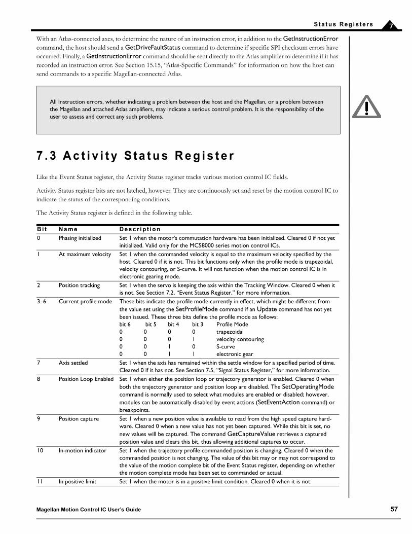
S t a t u s R e g i s t e r s 7
With an Atlas-connected axes, to determine the nature of an instruction error, in addition to the GetInstructionError command, the host should send a GetDriveFaultStatus command to determine if specific SPI checksum errors have occurred. Finally, a GetInstructionError command should be sent directly to the Atlas amplifier to determine if it has recorded an instruction error. See Section 15.15, “Atlas-Specific Commands” for information on how the host can send commands to a specific Magellan-connected Atlas.
7 . 3 A c t i v i t y S ta t u s R e g i s t e r
Like the Event Status register, the Activity Status register tracks various motion control IC fields.
Activity Status register bits are not latched, however. They are continuously set and reset by the motion control IC to indicate the status of the corresponding conditions.
The Activity Status register is defined in the following table.
All Instruction errors, whether indicating a problem between the host and the Magellan, or a problem between the Magellan and attached Atlas amplifiers, may indicate a serious control problem. It is the responsibility of the user to assess and correct any such problems.
B i t N a m e D e s c r i p t i o n
0 Phasing initialized Set 1 when the motor's commutation hardware has been initialized. Cleared 0 if not yet initialized. Valid only for the MC58000 series motion control ICs.
1 At maximum velocity Set 1 when the commanded velocity is equal to the maximum velocity specified by the host. Cleared 0 if it is not. This bit functions only when the profile mode is trapezoidal, velocity contouring, or S-curve. It will not function when the motion control IC is in electronic gearing mode.
2 Position tracking Set 1 when the servo is keeping the axis within the Tracking Window. Cleared 0 when it is not. See Section 7.2, “Event Status Register,” for more information.
3–6 Current profile mode These bits indicate the profile mode currently in effect, which might be different from the value set using the SetProfileMode command if an Update command has not yet been issued. These three bits define the profile mode as follows:bit 6 bit 5 bit 4 bit 3 Profile Mode0 0 0 0 trapezoidal0 0 0 1 velocity contouring0 0 1 0 S-curve0 0 1 1 electronic gear
7 Axis settled Set 1 when the axis has remained within the settle window for a specified period of time. Cleared 0 if it has not. See Section 7.5, “Signal Status Register,” for more information.
8 Position Loop Enabled Set 1 when either the position loop or trajectory generator is enabled. Cleared 0 when both the trajectory generator and position loop are disabled. The SetOperatingMode command is normally used to select what modules are enabled or disabled; however, modules can be automatically disabled by event actions (SetEventAction command) or breakpoints.
9 Position capture Set 1 when a new position value is available to read from the high speed capture hard-ware. Cleared 0 when a new value has not yet been captured. While this bit is set, no new values will be captured. The command GetCaptureValue retrieves a captured position value and clears this bit, thus allowing additional captures to occur.
10 In-motion indicator Set 1 when the trajectory profile commanded position is changing. Cleared 0 when the commanded position is not changing. The value of this bit may or may not correspond to the value of the motion complete bit of the Event Status register, depending on whether the motion complete mode has been set to commanded or actual.
11 In positive limit Set 1 when the motor is in a positive limit condition. Cleared 0 when it is not.
Magellan Motion Control IC User’s Guide 57

S t a t u s R e g i s t e r s7
The command GetActivityStatus returns the contents of the Activity Status register for the specified axis.
7 . 4 D r i v e S ta t u s R e g i s t e r ( I O N , M C 5 8 11 3 -S e r i e s , a n d A t l a s - C o n n e c t e d A x e s O n l y )
The Drive Status register functions similarly to the Activity Status register in that it continuously tracks various motion control IC fields. In other words, Drive Status register bits are not latched; they are continuously set and reset by the motion control IC to indicate the status of the corresponding conditions. The specific status bits provided by the Drive Status register are defined in the following table.
See Chapter 15, “Drive Control,” for more information on undervoltage, in foldback, overtemperature, and overvoltage. See Chapter 14, “Step Motor Control,” for more information on holding current.
The command GetDriveStatus returns the contents of the Drive Status register for the specified axis.
12 In negative limit Set 1 when the motor is in a negative limit condition. Cleared 0 when it is not.13–15 Profile segment Indicates the S-curve segment number, 1–7. See Section 4.3, “S-curve Point-to-Point
Profile,” for more information. A value of 0 in this field indicates the trajectory is not in motion. This field is undefined for other profile modes and may contain 0s or 1s.
B i t N a m e D e s c r i p t i o n
0 Reserved May contain 0 or 1.1 In foldback Set 1 when in foldback, cleared 0 if not in foldback.
Note: Depending on the application, when this condition occurs it may be neces-sary to power down the system and check for proper operation or service.
2 Overtemperature Set 1 when the axis is currently in an overtemperature condition. Cleared 0 if the axis is currently not in an overtemperature condition. Note: Depending on the application, when this condition occurs it may be neces-sary to power down the system and check for proper operation or service.
3 Reserved May contain 0 or 1.4 In holding Set 1 when the axis is in a holding current condition, cleared 0 if not.5 Overvoltage Set 1 when the axis is currently in an overvoltage condition. Cleared 0 if the axis is
currently not in an overvoltage condition. Note: Depending on the application, when this condition occurs it may be neces-sary to power down the system and check for proper operation or service.
6 Undervoltage Set 1 when the axis is currently in an undervoltage condition. Cleared 0 if the axis is currently not in an undervoltage condition. Note: Depending on the application, when this condition occurs it may be neces-sary to power down the system and check for proper operation or service.
7 Disabled Set 1 when the attached amplifier’s Enable signal is not active. Cleared 0 when the amplifier Enable signal is active. (Atlas-connected axes only).
8-11 Reserved12 Output Clipped Set 1 when the amplifier current command can not be met because of output clip-
ping. This information is used by Magellan to prevent PID saturation (MC58113 and Atlas-connected axes only).
13, 14 Reserved15 Drive Not Connected Set 1 when communication to connected amplifier has not yet been established.
Cleared 0 when successfully communication with the amplifier has been estab-lished. (Atlas-connected axes only).
B i t N a m e D e s c r i p t i o n
58 Magellan Motion Control IC User’s Guide

S t a t u s R e g i s t e r s 7
7 . 5 S i g n a l S ta t u s R e g i s t e r
The Signal Status register provides real-time signal levels for various motion control IC I/O pins. The Signal Status register is defined in the following table.
The command GetSignalStatus returns the contents of the Signal Status register for the specified axis. All Signal Status register bits are inputs except bit 10 (AxisOut) and bit 14 (FaultOut).
The input bits in the Signal Status register represent the actual hardware signal level combined with the state of the signal sense mask described in the next section. That is, if the signal level at the motion control IC is high, and the corresponding signal mask bit is 0 (do not invert), then the bit read using GetSignalStatus will be 1. Conversely, if the signal mask for that bit is a 1 (invert), then a high signal on the pin will result in a read of 0 using the GetSignalStatus command.
The outputs in the Signal Status register are not affected by the signal sense mask. For these signals a 1 indicates an active condition and a 0 indicates a non active condition.
The actual interpretation of the signal is dependent on its function. For example, Index, Home, Negative Limit, and Positive Limit are interpreted as active low, meaning that if a 0 is read using the GetSignalStatus command, the signal is active. Using the Negative Limit signal as an example, if GetSignalStatus indicates a value of 0, the motion control IC interprets this to mean that the axis is in the negative limit switch. Other signals such as HallA, HallB, HallC, AxisIn, and AxisOut do not have an active high or active low interpretation as such. Refer to the sections of the manual that describe these hardware functions for details on how these signals are used by the motion control IC.
7 . 5 . 1 S i g n a l S e n s e M a s k
The bits in the Signal Status register represent the high/low state of various signal pins on the motion control IC. It is possible to invert the incoming signal under software to match the signal interpretation of the user’s hardware. This function is accessed via the command SetSignalSense, and can be read back using the command GetSignalSense.
B i t N a m e D e s c r i p t i o n
0 A encoder A signal of quadrature encoder input.1 B encoder B signal of quadrature encoder input.2 Index encoder Index signal of quadrature encoder input.3 Home/Capture For MC50000, this bit holds the home signal input.
For ION, this bit holds the home signal, the HighSpeedCapture signal, or the Index signal, depending on which was set as the high speed capture. See Section 10.2, “High-Speed Position Capture” for details on setting high speed capture.
4 Positive limit Positive limit switch input.5 Negative limit Negative limit switch input.6 AxisIn Generic axis input signal.7 Hall1 Hall effect sensor input number 1. 8 Hall2 Hall effect sensor input number 2.9 Hall3 Hall effect sensor input number 3.10 AxisOut AxisOut output.11–12 Reserved May contain 0 or 1.13 /Enable Enable signal input (ION and MC58113 only).14 FaultOut Fault signal output (ION and MC58113 only).15 Reserved May contain 0 or 1.
Magellan Motion Control IC User’s Guide 59
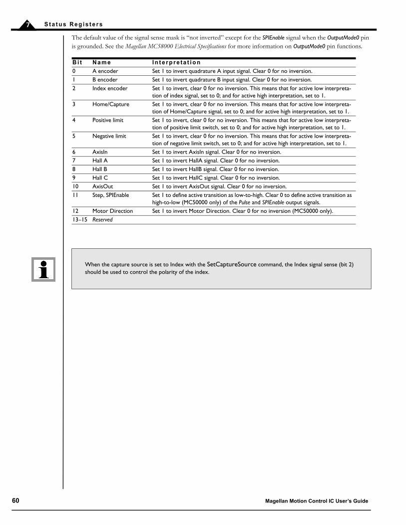
S t a t u s R e g i s t e r s7
The default value of the signal sense mask is “not inverted” except for the SPIEnable signal when the OutputMode0 pin is grounded. See the Magellan MC58000 Electrical Specifications for more information on OutputMode0 pin functions.
B i t N a m e I n t e r p r e ta t i o n
0 A encoder Set 1 to invert quadrature A input signal. Clear 0 for no inversion.1 B encoder Set 1 to invert quadrature B input signal. Clear 0 for no inversion.2 Index encoder Set 1 to invert, clear 0 for no inversion. This means that for active low interpreta-
tion of index signal, set to 0; and for active high interpretation, set to 1.3 Home/Capture Set 1 to invert, clear 0 for no inversion. This means that for active low interpreta-
tion of Home/Capture signal, set to 0; and for active high interpretation, set to 1.4 Positive limit Set 1 to invert, clear 0 for no inversion. This means that for active low interpreta-
tion of positive limit switch, set to 0; and for active high interpretation, set to 1.5 Negative limit Set 1 to invert, clear 0 for no inversion. This means that for active low interpreta-
tion of negative limit switch, set to 0; and for active high interpretation, set to 1.6 AxisIn Set 1 to invert AxisIn signal. Clear 0 for no inversion.7 Hall A Set 1 to invert HallA signal. Clear 0 for no inversion.8 Hall B Set 1 to invert HallB signal. Clear 0 for no inversion.9 Hall C Set 1 to invert HallC signal. Clear 0 for no inversion.10 AxisOut Set 1 to invert AxisOut signal. Clear 0 for no inversion.11 Step, SPIEnable Set 1 to define active transition as low-to-high. Clear 0 to define active transition as
high-to-low (MC50000 only) of the Pulse and SPIEnable output signals.12 Motor Direction Set 1 to invert Motor Direction. Clear 0 for no inversion (MC50000 only).13–15 Reserved
When the capture source is set to Index with the SetCaptureSource command, the Index signal sense (bit 2) should be used to control the polarity of the index.
60 Magellan Motion Control IC User’s Guide

8
8 . M o t i o n M o n i t o r i n g a n d R e l a t e d P r o c e s s i n g
In This ChapterSetEventAction Processing Motion Error Travel-Limit Switches Tracking Window Motion Complete Indicator In-Motion Indicator Settle Window Trace Capture Trace Buffer Architecture Host Interrupts
8 . 1 S e t E v e n t A c t i o n P r o c e s s i n g
The Magellan Motion Control ICs provide a programmable mechanism for reacting to various safety or performance-related conditions.
The command SetEventAction is used to specify what action should be taken for a given condition. To define an event-related response, both a condition and an action must be specified. The following table lists the possible Event Status
register conditions that can be used to define an event-related action.
Both motion error processing and limit switch processing are described in detail later in this chapter. See Section 15.11, “Current Foldback” for more information on current foldback. In addition to these four monitored conditions it is
C o n d i t i o n N a m e D e s c r i p t i o n
Motion error A motion error occurs when the position error exceeds a programmable threshold.
Positive limit A positive limit event occurs when the corresponding signal goes active while the motor velocity is positive.
Negative limit A negative limit event occurs when the corresponding signal goes active while the motor velocity is negative.
Current foldback (ION, MC58113-series, and Atlas-connected Magellan axes only). A current foldback event occurs when the amplifier current output goes into a foldback condition.
Magellan Motion Control IC User’s Guide 61

M o t i o n M o n i t o r i n g a n d R e l a t e d P r o c e s s i n g8
possible to request an immediate safety action. See the Magellan Motion Control IC Programmer’s Command Reference for more information.
The following table describes the actions that can be programmed for these conditions.
Once the event condition is programmed, the motion control IC monitors the specified condition continuously and executes the programmed action if it occurs. Upon occurrence, the programmed action is executed, and related actions may occur such as setting the appropriate bit in the Event Status register.
To recover from an event action, the command RestoreOperatingMode is used. This command will reset the motion control IC to the operating mode previously specified using SetOperatingMode command. Note that if the event condition is still present, then the event action will immediately occur again.
If the event action programmed was either No Action, Abrupt Stop, or Smooth Stop, then the RestoreOperatingMode command will have no effect. It is intended to restore disabled modules only, and has no effect on trajectory generator parameters.
Once programmed, an event action will be in place until reprogrammed. The occurrence of the event condition does not reset the programmed event action.
Magellan provides default values for event-related processing. These defaults are intended to provide safe operation for many typical motion systems. Whether or not these defaults are appropriate must be determined by the user.
The default event actions are summarized in the following table.
A c t i o n N a m e D e s c r i p t i o n
No Action No action taken.Smooth Stop Causes a smooth stop to occur at the current active deceleration rate.
The velocity command will be set to zero after event action occurs.Abrupt Stop Causes an instantaneous halt of the trajectory generator. The velocity
command will be set to zero (0) after event action occurs.Abrupt Stop with Position Error Clear Causes an instantaneous halt of the trajectory generator as well as a zeroing
of the position error (equivalent to ClearPositionError command). The velocity command will be set to zero (0) after event action occurs.
Disable Position Loop & Higher Modules Disables trajectory generator and position loop module.Disable Current Loop & Higher Modules Disables trajectory generator, position loop, and current loop modules.Disable Motor Output & Higher Modules Disables trajectory generator, position loop, current loop, and motor
output modules.
It is the responsibility of the user to safely and thoroughly investigate the cause of event-related events, and only restart motion operations when appropriate corrective measures have been taken.
C o n d i t i o n D e f a u l t A c t i o n
Motion Error Disable position loop and trajectory generator.Positive & Negative Limit Abrupt Stop with Position Error Clear.Current Foldback Disable motor output and higher modules.
62 Magellan Motion Control IC User’s Guide

M o t i o n M o n i t o r i n g a n d R e l a t e d P r o c e s s i n g 8
8 . 2 M o t i o n E r r o r
Under certain circumstances the actual axis position (encoder position) may differ from the commanded position (instantaneous output of the profile generator) by an excessive amount. Such an excessive position error often indicates a potentially dangerous condition such as motor failure, encoder failure, or excessive mechanical friction.
To detect this condition, as well as increasing safety and equipment longevity, the Magellan Motion Control ICs include a programmable maximum position error.
The maximum position error is set using the command SetPositionErrorLimit, and read using the commandGetPositionErrorLimit. To determine whether a motion error has occurred, the position error limit is continuously compared against the actual position error. If the position error limit value is exceeded, then the axis is said to have had a motion error.
At the moment a motion error occurs, several events occur simultaneously. The motion error bit of the Event Status register is set. If the default event action for motion error has not been modified, then the trajectory generator and position loop are disabled. For servo axes this means the manually-set Motor Command register will be used as the motor output value. For step motors this means the axis will immediately stop. If a new event action for motion error has been specified, then whatever programmed action was entered will occur.
To recover from a motion error, the cause of motion error should be determined, and the problem corrected (this may require human intervention). If the event response resulted in a disabling of control modules, the host should then issue a RestoreOperatingMode command.
If an event action of No Action was programmed, then only the motion error status bit is set. In this case, no recovery sequence is required to continue operating the motion control IC. However, for safety reasons, the user may still want to manually stop motion, and determine the cause of the motion error.
Generally speaking, after a motion error the corresponding bit in the Event Status register is cleared using the command ResetEventStatus. For event actions of Smooth Stop, Abrupt Stop, and Abrupt Stop with Position Error Clear, clearing this bit is required to make a subsequent move. Although recommended, for event actions that disable modules, clearing this bit is not required to make a further move, nor is it required for an event action of No Action.
8 . 3 Tr a v e l - L i m i t S w i t c h e s
The Magellan Motion Control ICs support motion travel limit switches which may be used to automatically recognize an end-of-travel condition. This is an important safety feature for systems with a defined range of motion.
The following figure shows a schematic representation of an axis with travel-limit switches installed, indicating the legal motion area and the over-travel, or illegal region.
Figure 8-1: Directional Limit Switch Operation
negativeover-travel region
positiveover-travel region
Legal travel region
negativelimit switch
positivelimit switch
Magellan Motion Control IC User’s Guide 63

M o t i o n M o n i t o r i n g a n d R e l a t e d P r o c e s s i n g8
For detailed information on interfacing to these signals, see the Magellan Control ICElectrical Specification (motion control IC users), or the motion card or ION Digital Drive User’s Manual (card and module users).
At the moment a positive or negative limit switch event occurs, several events occur simultaneously. The corresponding overtravel bit of the Event Status register is set, along with a bit in the Activity Status register. If the default event action for positive and negative limits has not been modified, then the trajectory generator will undergo an abrupt stop and the position error will be cleared. If a new event action for overtravel has been defined, then whatever programmed action was entered will occur.
If an event action of No Action was programmed, then the limit status bit is not set, and no recovery sequence is required to continue operating the motion control IC.
To process limit switch events, the motion control IC will constantly monitor the limit switch input pins looking for a limit switch event. A limit switch event occurs when a limit switch goes active while the axis commanded position or torque is moving that motor in that limit switch’s direction. If the axis is not moving, or if the trajectory generator (or torque command) is moving the motor in the opposite direction, then a limit switch event will not occur. For example, a positive limit switch will occur when the axis commanded position is moving in the positive direction, and the positive limit switch goes active. However, it will not occur if the axis commanded position is moving in the negative direction or is stationary.
The sense of the limit switch inputs (active high or active low) may be controlled using the SetSignalSense command.
Once an axis has entered a limit switch condition, the following steps should be taken to clear the limit switch event.
1 Unless limit switch events can occur during normal machine operation, the cause of the event should beinvestigated and appropriate safety corrections made.
2 The limit switch bit(s) in the Event Status register should be cleared by issuing the ResetEventStatuscommand. Unless the programmed action was set to No Action, no motion is possible in any directionwhile either of the limit switch bits in the Event Status register are set.
3 If the default event action of Abrupt Stop with Position Error Clear is not altered, a move should be made inthe direction opposite to that which caused the limit switch event. This can be any profile move thatbacks the axis out of the limit. If the host attempts to move the axis further into the limit, a new limitevent will occur, and an instruction error will be generated. See Section 12.2.5, “Instruction Errors” formore information on instruction errors. Note that as part of the event action associated with the abruptstop, the Velocity register is loaded with zero (0). Thus a SetVelocity command must be sent along withany other desired profile parameters.
4 If the event action is altered from the default value such that a module is disabled, the host should issuea RestoreOperatingMode command to restore normal operation of the control loop. Then a reversingmove should be made as described in step #3.
If an event action of No Action is defined for limit switches, then only step 1 is required.
For axes in elecronic gearing mode, the above steps are modified slightly. After the ResetEventStatus, a SetGearRatio command followed by an Update command are required. This is because the limit event sets GearRatio to zero (0).
If the limit switches are wired to separate switches, then it should not be possible for both limit switches to be active at the same time. However, if this does occur (presumably due to a special wiring arrangement), then both limit switch bits in the Activity Status register will be set, thus disabling moves in either direction. In this case, the SetEventAction command should be used with a value of No Action to temporarily disable limit switch processing while the motor is moved off of the switches.
Limit switch processing generally is used with the trajectory generator module enabled. When the trajectory generator is disabled (for example during amplifier calibration), limit switch processing still occurs but the possible event actions
64 Magellan Motion Control IC User’s Guide
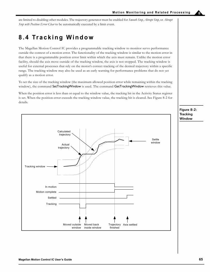
M o t i o n M o n i t o r i n g a n d R e l a t e d P r o c e s s i n g 8
are limited to disabling other modules. The trajectory generator must be enabled for Smooth Stop, Abrupt Stop, or Abrupt Stop with Position Error Clear to be automatically executed by a limit event.
8 . 4 Tr a c k i n g W i n d o w
The Magellan Motion Control IC provides a programmable tracking window to monitor servo performance outside the context of a motion error. The functionality of the tracking window is similar to the motion error in that there is a programmable position error limit within which the axis must remain. Unlike the motion error facility, should the axis move outside of the tracking window, the axis is not stopped. The tracking window is useful for external processes that rely on the motor’s correct tracking of the desired trajectory within a specific range. The tracking window may also be used as an early warning for performance problems that do not yet qualify as a motion error.
To set the size of the tracking window (the maximum allowed position error while remaining within the tracking window), the command SetTrackingWindow is used. The command GetTrackingWindow retrieves this value.
When the position error is less than or equal to the window value, the tracking bit in the Activity Status register is set. When the position error exceeds the tracking window value, the tracking bit is cleared. See Figure 8-2 for details.
Figure 8-2: Tracking Window
Settle window
Tracking window
Moved outside window
Moved back inside window
Trajectory finished
Axis settled
Actual trajectory
Calculatedtrajectory
In motion
Motion complete
Settled
Tracking
Magellan Motion Control IC User’s Guide 65

M o t i o n M o n i t o r i n g a n d R e l a t e d P r o c e s s i n g8
8 . 5 M o t i o n C o m p l e t e I n d i c a t o r
In many cases, it may be advantageous to have the motion control IC signal that a given motion profile is complete. This functionality is available in the motion complete indicator.
The motion complete indicator appears in bit 0 of the Event Status register. Like all bits in the Event Status register, the motion complete bit is set by the motion control IC and cleared by the host. When a motion is complete, the motion control IC sets the motion complete bit to on. The host can examine this bit by polling the Event Status register, or the host can program an automatic follow-on function using a breakpoint, a host interrupt, or an AxisOut signal. In either case, once the host has recognized that the motion has been completed, the host should clear the motion complete bit. This action will enable the bit to indicate the end of motion for the next move.
Motion complete can indicate the end of the trajectory motion in one of two ways. The first is commanded: the motion complete indicator is set based on the profile generator registers only. The other method is actual: the motion complete indicator is based on the actual encoder. The host instruction SetMotionCompleteMode determines which condition controls the indicator.
When set to commanded, the motion is considered complete when both trajectory generator registers for commanded velocity and acceleration become zero (0). This normally happens at the end of a move when the destination position has been reached. It may also happen as the result of a stop command (SetStopMode command), a change of velocity to zero (0), or when a limit switch event occurs, or after a motion error occurs.
When set to actual, the motion is considered complete when all of the following actions have occurred:
The profile generator (commanded) motion is complete.
The difference between the actual position and the commanded position is less than or equal to the value ofthe settle window. The settle window is set using the command SetSettleWindow. This same value may beread back using the command GetSettleWindow. See Section 8.7, “Settle Window” for more informationon the settled window.
The two previous conditions have been met continuously for the last N cycles, where N is the programmedsettle time. The settle time is set using the command SetSettleTime. This same value may be read back usingthe command GetSettleTime.
At the end of the trajectory profile, the cycle timer for the actual-based motion complete mechanism is cleared, so there will always be at least an N cycle delay (where N is the settle time) between the profile generator being completed point-to-point, and the motion complete bit being set. The motion complete bit functions in the S-curve point-to-point trapezoidal point-to-point, and velocity contouring profile modes only. It does not function when the profile mode is set to electronic gearing.
8 . 6 I n - M o t i o n I n d i c a t o rThe motion control IC can indicate whether or not the axis is moving. This function is available through the in-motion indicator.
The in-motion indicator appears in bit 10 of the Activity Status register. The in-motion bit is similar to the motion complete bit, however, there are two important differences. The first is that (like all bits in the Activity Status register)
Appropriate software methods should be used with the actual motion complete mode, because it is possible that the motion complete bit will never be set if the servo is not tracking well enough to stay within the programmed position error window for the specified settle time.
66 Magellan Motion Control IC User’s Guide

M o t i o n M o n i t o r i n g a n d R e l a t e d P r o c e s s i n g 8
the in-motion indicator continuously indicates its status without interaction with the host. In other words, the in-motion bit cannot be set or cleared by the host. The other difference is that this bit always indicates the profile generator (commanded) state of motion, not the actual encoder.
The in-motion indicator bit functions in the S-curve point-to-point, trapezoidal point-to-point, and velocity contouring profile modes only. It does not function when the profile mode is set to electronic gearing.
8 . 7 S e t t l e W i n d o wThe motion control IC can also continuously indicate whether or not the axis has settled.
The settled indicator appears in bit 7 of the Activity Status register. The settled indicator is similar to the motion complete bit when the motion complete mode is set to actual. The differences are that the settled indicator continuously indicates its status (cannot be set or cleared).
The axis is considered to be settled when the axis is at rest (i.e., not performing a trajectory profile), and when the actual motor position has settled at the commanded position for the programmed settle time.
The settle window and settle time used with the settled indicator are the same as the motion complete bit when set to actual. Correspondingly, the same commands are used to set and read these values: Set/GetSettleWindow and Set/GetSettleTime.
It is recommended that the motion complete bit be used for determining when a motion profile has finished.
Figure 8-3: Settle Window
Settle window
Tracking window
Axis settled
Actual trajectory
Calculatedtrajectory
Trajectory finished;settle timer started
Axis out of window; settle timer stopped
and reset
Axis back inside window; settle timer restarted
In motion
Motion complete
Settled
Magellan Motion Control IC User’s Guide 67

M o t i o n M o n i t o r i n g a n d R e l a t e d P r o c e s s i n g8
8 . 8 Tr a c e C a p t u r e
Trace capture is a powerful feature of the Magellan Motion Control IC that allows various motion control IC parameters and registers to be continuously captured and stored to a memory buffer. The captured data may later be downloaded by the host using standard memory buffer access commands. Data traces are useful for optimizing servo performance, verifying trajectory behavior, capturing sensor data, or to assist with any type of monitoring where a precise time-based record of the system’s behavior is required.
Trace data capture (by the motion control IC) and trace data retrieval (by the host) are executed as two separate processes. The host specifies which parameters will be captured, and how the trace will be executed. Then the motion control IC performs the trace. Finally, the host retrieves the data after the trace is complete. It is also possible to perform continuous data retrieval, even as the motion control IC is continuing to collect additional trace data.
8 . 9 Tr a c e B u f f e r A r c h i t e c t u r e
The Magellan’s powerful trace feature relies on the availability of a data memory pool which can be accessed by the motion control IC. For MC55000 series and MC58000 series card level designs, this memory is located externally to the motion control IC, and typically takes the form of single or dual ported static RAM. How much RAM, and what type of RAM, is up to the user that is designing the card, and generally is determined by the number of desired trace elements multiplied by the desired time duration of the trace.
For PMD’s off-the-shelf motion cards using the MC55000 or MC58000 processors, the amount of external RAM is fixed, and is described in the corresponding user’s guide for that product. Most of these cards provide the trace RAM in a dual port architecture, so that data can be read from the port at high speed directly through the parallel bus, even while the motion control IC is writing trace data to the buffer.
ION and MC58113-series ICs also support a trace buffer, however these buffers are located within the motion control IC itself. ION has a fixed size of 1,536 bytes (1.5 KBytes), while the MC58113 has a fixed size of 32,768 bytes (32 KBytes).
To start a trace, the host must specify a number of parameters. They are:
Maintaining the trace buffer requires the motion control IC to perform extra work during each cycle. In very high-performance scenarios (such as a single axis configuration running at maximum speed), the user may have to in-crease the chip cycle (servo loop) time. See Section 3.4, “Setting the Cycle Time” for more information on cycle time requirements. Most applications should disable trace capture once the motion profile has been debugged.
P a r a m e t e r D e s c r i p t i o n
Trace buffer The host must initialize the data trace buffer memory. The Magellan Motion Control IC provides special instructions to initialize external memory into buffers, allowing various sizes and start loca-tions of external memory to be used for tracing. For ION and MC58113, buffer initialization is not required, as its size and location is fixed.
Trace variables Depending on the motion control IC type, there are many dozens of separate items within the motion control IC that may be traced; for example, actual position, Event Status register, position error, etc. The user must specify the variables and the axes from which data will be recorded.
Trace period The motion control IC can capture the value of the trace variables for every single motion control IC cycle, every other cycle, or at any programmed frequency. The period of data collection and stor-age must be specified.
Trace mode The motion control IC can trace in one of two modes: one-time, or rolling mode. This determines how the data is stored, and whether the trace will stop automatically or whether it must be stopped by the host.
68 Magellan Motion Control IC User’s Guide

M o t i o n M o n i t o r i n g a n d R e l a t e d P r o c e s s i n g 8
8 . 9 . 1 T h e Tr a c e B u f f e r
The Magellan Motion Control IC organizes external memory into data buffers. Each buffer is given a numerical ID. The trace buffer must always be ID 0 (zero). For MC55000 and MC58000 series processors except MC58113, before parameter traces may be used, memory buffer 0 must be programmed with a valid base address and length. For IONs and MC58113, memory buffer 0 has been pre-configured. No initialization is required, and the remaining comments in this section on the trace buffer do not apply.
The size of the trace buffer determines the maximum number of data points that can be captured. The maximum size of the trace buffer is only limited by the amount of physical memory in the system. The addressable memory space allows up to 2,048 megawords of RAM to be installed, all of which may be used to store trace information.
While trace data is being collected, it is not legal to change the trace buffer configuration. If an attempt is made to change the base address, length, or write pointer associated with buffer 0 while a trace is running, the change will be ignored and an error will be flagged. It is possible to change the read pointer and read data from the trace buffer while a trace is running. This allows the buffer to be constantly emptied while the trace runs.
8 . 9 . 2 T h e Tr a c e P e r i o d
The tracing system supports a configurable period register that defines the frequency at which data is stored to the trace buffer. The tracing frequency is specified in units of motion control IC cycles, where one cycle is the time required to process all enabled axes.
The command SetTracePeriod sets the trace period, and the command GetTracePeriod retrieves it.
8 . 9 . 3 Tr a c e Va r i a b l e s
When traces are running, one to four motion control IC parameters may be stored to the trace buffer for every trace period. The four trace variable registers are used to define which parameters are stored. The following commands are used to configure the trace variables.
The command SetTraceVariable selects which traceable parameter will be stored by the trace variable specified. The command GetTraceVariable retrieves this same value.
The value passed and returned by the two preceding commands specifies the variable number, axis, and type of data to be stored. The first 16-bit word specifies the variable number, and the second 16-bit word specifies the axis number and variable ID as follows:
Many variables are available for trace on all Magellan ICs and on ION. Current or drive-related parameters are available for trace on ION and MC58113 only. Atlas-connected systems can trace current and drive-related parameters, however these traces must be executed on the Atlas amplifier rather than the Magellan. See Section 8.9.4, “Atlas Traces” for more information on this.
Trace start/stop conditions
To allow precise synchronization of data collection, it is possible to define the start and stop con-ditions for a given trace. The motion control IC monitors these specified conditions and starts or stops the trace automatically without host intervention.
B i ts N a m e D e s c r i p t i o n
0–3 TraceAxis Selects the source axis for the parameter.4–7 Reserved Must be written as zero.8–15 VariableID Selects the parameter to be stored.
P a r a m e t e r D e s c r i p t i o n
Magellan Motion Control IC User’s Guide 69
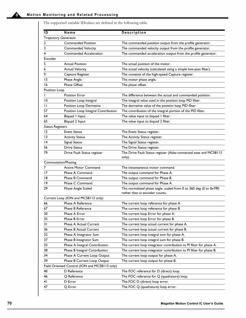
M o t i o n M o n i t o r i n g a n d R e l a t e d P r o c e s s i n g8
The supported variable IDvalues are defined in the following table.
I D N a m e D e s c r i p t i o n
Trajectory Generator2 Commanded Position The commanded position output from the profile generator. 3 Commanded Velocity The commanded velocity output from the profile generator.4 Commanded Acceleration The commanded acceleration output from the profile generator.Encoder5 Actual Position The actual position of the motor.6 Actual Velocity The actual velocity (calculated using a simple low-pass filter).9 Capture Register The contents of the high-speed Capture register.15 Phase Angle The motor phase angle.16 Phase Offset The phase offset.Position Loop1 Position Error The difference between the actual and commanded position. 10 Position Loop Integral The integral value used in the position loop PID filter.11 Position Loop Derivative The derivative value of the position loop PID filter.57 Position Loop Integral Contribution The contribution of the integral portion of the PID filter.64 Biquad 1 Input The value input to biquad 1 filter.65 Biquad 2 Input The value input to biquad 2 filter.Status Registers12 Event Status The Event Status register.13 Activity Status The Activity Status register.14 Signal Status The Signal Status register.56 Drive Status The Drive Status register.79 Drive Fault Status register The Drive Fault Status register (Atlas-connected axes and MC58113
only).Commutation/Phasing7 Active Motor Command The instantaneous motor command.17 Phase A Command The output command for Phase A.18 Phase B Command The output command for Phase B.19 Phase C Command The output command for Phase A.29 Phase Angle Scaled The normalized phase angle, scaled from 0 to 360 deg (0 to 0x7fff)
rather than in encoder counts.Current Loop (ION and MC58113 only)66 Phase A Reference The current loop reference for phase A.67 Phase B Reference The current loop reference for phase B.30 Phase A Error The current loop Error for phase A.35 Phase B Error The current loop Error for phase B.31 Phase A Actual Current The current loop actual current for phase A.36 Phase B Actual Current The current loop actual current for phase B.32 Phase A Integrator Sum The current loop integral sum for phase A.37 Phase B Integrator Sum The current loop integral sum for phase B.33 Phase A Integral Contribution The current loop integrator contribution to PI filter for phase A.38 Phase B Integral Contribution The current loop integrator contribution to PI filter for phase B.34 Phase A Current Loop Output The current loop output for phase A.39 Phase B Current Loop Output The current loop output for phase B.Field Oriented Control (ION and MC58113 only)40 D Reference The FOC reference for D (direct) loop.46 Q Reference The FOC reference for Q (quadrature) loop.41 D Error The FOC D (direct) loop error.47 Q Error The FOC Q (quadrature) loop error.
70 Magellan Motion Control IC User’s Guide

M o t i o n M o n i t o r i n g a n d R e l a t e d P r o c e s s i n g 8
Setting a trace variable’s parameter to zero will disable that variable and all subsequent variables. Therefore, if N parameters are to be saved each trace period, trace variables 0 to (N–1) must be used to identify the parameters to be saved, and trace variable N must be set to zero. Note that N 4.
For example, assume that the actual and commanded position values are to be stored for axis three for each cycle period. The following commands would be used to configure the trace variables.
SetTraceVariable 0, 0202h // Sets trace variable 0 to store parameter 2 (commanded // position) for axis 3.
SetTraceVariable 1, 0502h // Sets trace variable 1 to store parameter 5 (actual // position) for axis 3.
42 D Feedback The FOC D (direct) feedback current.48 Q Feedback The FOC Q (quadrature) feedback current.43 D Integrator Sum The FOC integral for D (direct) loop.49 Q Integrator Sum The FOC integral for Q (quadrature) loop.44 D Integral Contribution The FOC integrator contribution for D (direct) loop.50 Q Integral Contribution The FOC integrator contribution for Q (quadrature) loop.45 D Output The FOC output for D (direct) loop.51 Q Output The FOC output Q (quadrature) loop.52 FOC Alpha Output The FOC output for phase Alpha.53 FOC Beta Output The FOC output for phase Beta.31 Phase A Actual Current The FOC actual current for phase A (same ID # as in current loop).36 Phase B Actual Current The FOC actual current for phase B (same ID # as in current loop).Drive Related (ION and MC58113 only)75 PWM output A Phase A PWM output (MC58113 only)76 PWM output B Phase B PWM output (used with Brushless DC motors only,
MC58113 only)77 PWM output C Phase C PWM output (used with Brushless DC and step motors
only, MC58113 only)68 i2t foldback energy The i2t total foldback energy54 Bus Voltage The bus voltage.55 Temperature The temperature of the drive’s output stage.86 Bus current supply The DC bus supply current (MC58113 only)87 Bus current return The DC bus return current (MC58113 only)69 Leg current A Current1A reading (MC58113 only)70 Leg current B Current1B reading (MC58113 only)71 Leg current C Current1C reading (MC58113 only)72 Leg current D Current1D reading (MC58113 only)Analog inputs, (MC5x000 ICs except MC58113)20 Analog0 input The most recently read value from the Analog0 signal.21 Analog1 input The most recently read value from the Analog1signal.22 Analog2 input The most recently read value from the Analog2 signal.23 Analog3 input The most recently read value from the Analog3 signal.24 Analog4 input The most recently read value from the Analog4 signal.25 Analog5 input The most recently read value from the Analog5 signal.26 Analog6 input The most recently read value from the Analog6 signal.27 Analog7 input The most recently read value from the Analog7 signal.Analog inputs (MC58113 only)20 Analog1 input The most recently read value from the Analog1 signal.Miscellaneous0 None No trace variable selected.8 Motion Control IC Time The motion control IC time (units of servo cycles).
I D N a m e D e s c r i p t i o n
Magellan Motion Control IC User’s Guide 71

M o t i o n M o n i t o r i n g a n d R e l a t e d P r o c e s s i n g8
SetTraceVariable 2, 0002h // Disables trace variables 2 (and higher).
8 . 9 . 4 A t l a s Tr a c e s
Atlas amplifiers have a dedicated trace facility located inside the Atlas drive to record trace data. Traceable data includes current control-related variables, drive-related variables such as voltage and temperature, as well as many other variables.
Atlas can trace data at a user-specified rate, or at a rate synchronous with the Magellan capture rate. Atlas has the ability to start and stop traces based on specific user-specified conditions, or in synchrony with Magellan trace start and stop conditions.
Many users will utilize PMD’s Windows-based software Pro-Motion to seamless specify, perform, and analyze traces on Magellan as well as Atlas. Users interested in programming these capabilities into their own system can learn how this is accomplished via the Atlas Digital Amplifier Complete Technical Reference as well as the Magellan Motion Control IC Programmer’s Command Reference.
8 . 9 . 5 Tr a c e M o d e s
As trace data is collected, it is written to sequential locations in the trace buffer. When the end of the buffer is reached, the trace mechanism will behave in one of two ways, depending on the selected mode.
If one-time mode is selected, then the trace mechanism will stop collecting data when the buffer is full.
If rolling-buffer is selected, then the trace mechanism will wrap around to the beginning of the trace buffer and continue storing data. Data from previous cycles will be overwritten by data from subsequent cycles. In this mode, the diagnostic trace will not end until the conditions specified in a SetTraceStop command are met.
Use the command SetTraceMode to select the trace mode. The command GetTraceMode retrieves the trace mode.
8 . 9 . 6 Tr a c e S ta r t / S t o p C o n d i t i o n s
The command SetTraceStart is used to specify the conditions that will cause the trace mechanism to start collecting data. A similar command (SetTraceStop) is used to define the condition that will cause the trace mechanism to stop collecting data. Both SetTraceStart and SetTraceStop require a 16-bit word of data, which contains four encoded parameters. This is detailed in the following tables.
The Trigger Type field must contain one of the following values.
B i ts N a m e D e s c r i p t i o n
0–3 Trigger Axis For trigger types other than Immediate, this field determines which axis will be used as the source for the trigger. Use 0 for axis 1, 1 for axis 2, etc.
4–7 Condition Defines the type of trigger to be used. See the following table for a complete list of trigger types.
8–11 Trigger bit For trigger types based on a status register, this field determines which bit (0–15) of the sta-tus register will be monitored.
12–15 Trigger State For trigger types based on a status register, this field determines which state (0 or 1) of the specified bit will cause a trigger.
I D N a m e D e s c r i p t i o n
0 Immediate This trigger type indicates that the trace starts (stops) immediately when the SetTraceStart (SetTraceStop) command is issued. If this trigger type is specified, the trigger axis, bit num-ber, and bit state value are not used.
1 Update The trace will start (stop) on the next update of the specified trigger axis. This trigger type does not use the bit number or bit state values.
72 Magellan Motion Control IC User’s Guide

M o t i o n M o n i t o r i n g a n d R e l a t e d P r o c e s s i n g 8
8 . 9 . 7 D o w n l o a d i n g Tr a c e D a ta
Once a trace has executed and the trace buffer is full (or partially full) of data, the captured data may be downloaded by the host using the standard commands to read from the external buffer memory. See Section 16.1.2, “Memory Buffer Commands” for a complete description of external memory buffer commands.
At any time, the command GetTraceCount may be used to get the number of 32-bit words of data stored in the trace buffer. This value may be used to determine the number of ReadBuffer commands that must be issued to download the entire contents of the trace buffer.
During each trace period, each of the trace variables is used in turn to store a 32-bit value to the trace buffer. Therefore, when data is read from the buffer, the first value read would be the value corresponding to trace variable 1, the second value will correspond to trace variable 2, up to the number of trace variables used.
Both the length of the trace buffer and the number of trace variables set directly affect the number of trace samples that may be stored. For example, if the trace buffer is set to 1000 words (each 32-bits), and two trace variables are initialized (variables 0 and 1), then up to 500 trace samples will be stored. However, if three trace variables are used, then 333 full trace samples may be stored. In this case, the remaining word of data will store the first variable from the 334th sample.
If the trace mode is set to RollingBuffer, then the 334th trace sample will store the first word in the last location of the trace buffer, and the second and third words will be stored in locations 0 and 1, respectively. In this case, the first two words of sample 333 have been overwritten by the last two words of sample 334. When the trace is stopped, the read pointer will point to the oldest word of data in the buffer. This word may not correspond to the first word of a trace sample.
Therefore, it is recommended that the length of the trace buffer be set so that it is an even multiple of the number of trace variables being used. This will ensure that the read index is pointing to the first word in a complete trace sample; whether or not the trace buffer wraps. The simplest solution is to verify that the trace buffer length is an even multiple of 12 (since 12 is evenly divisible by all possible numbers of trace variables: 1, 2, 3, or 4).
8 . 9 . 8 R u n n i n g Tr a c e s
The following is a summary of data trace operations to assist in getting started.
1 Specify the data to be stored. The command SetTraceVariable is used to specify up to four variables tobe stored for each trace period. The location of trace variables must be used contiguously. For example,to trace two variables, use trace variables 1 and 2. To trace three variables, use trace variables 1, 2, and 3.The first trace variable found that is set to none (refer to SetTraceVariable in the Magellan Motion ControlIC Programmer's Command Reference) is assumed to be the last variable being traced. If trace variable 1 is setto none and trace variable 2 is set to actual position, then no variables will be traced since the firstvariable (set to none) specifies the end of variables being traced. If four variables are being traced, do notset any variables to none since all variable locations are being used.
2 (MC50000 only) Set up the trace buffer. Using the commands SetBufferStart and SetBufferLength,define the location in external RAM where trace data should be stored, and the amount of RAM to beused to hold the trace data. The trace data will be stored in the buffer with an ID of zero. Be careful notto extend the buffer beyond the amount of available physical RAM. Keep in mind that SetBufferStartand SetBufferLength specify values based on a 32-bit word size.
2 Event Status The specified bit in the Event Status register will be constantly monitored. When that bit enters the defined state (0 or 1), then the trace will start (stop).
3 Activity Status The specified bit in the Activity Status register will be constantly monitored. When that bit enters the defined state (0 or 1), then the trace will start (stop).
4 Signal Status The specified bit in the Signal Status register will be constantly monitored. When that bit enters the defined state (0 or 1), then the trace will start (stop).
5 Drive Status The specified bit in the Drive Status register will be constantly monitored. When that bit enters the defined state (0 or 1), then the trace will start (stop).
I D N a m e D e s c r i p t i o n
Magellan Motion Control IC User’s Guide 73

M o t i o n M o n i t o r i n g a n d R e l a t e d P r o c e s s i n g8
3 Set the trace period. The command SetTracePeriod sets the interval between trace samples in units ofcycles. The minimum is one cycle.
4 Set the trace mode. If the trace is to be started on a specific event, then the One Time mode should probablybe used. This will allow one buffer full of trace data to be stored, beginning with the starting event (set usingSetTraceStart). Alternatively, if the trace is to stop on an event (as specified using SetTraceStop), then therolling buffer mode should be used. This will cause the system to constantly record data until the stoppingevent occurs. At that point, the data leading up to the event will be saved in the trace buffer.
5 Set the stopping mode (if desired). If a specific event will cause the trace to stop, then it should be programmedusing the SetTraceStop command. However, if the trace is to be programmed to stop when the buffer fillsup (by setting the trace mode to One Time), then it is not necessary to set another stopping event. Also, at anytime while the trace is running, the SetTraceStop command may be issued to immediately stop the trace.
6 Start the trace. The SetTraceStart command may be used to start the trace directly (by specifying theImmediate trigger type). Alternatively, a triggering event may be specified to start the trace when thiscommand occurs.
8 . 1 0 H o s t I n t e r r u p ts
Interrupts allow the host to become aware of a special motion control IC condition without the need for continuous monitoring or polling of the status registers. The Magellan Motion Control ICs provide this service in the form of a host interrupt.
The actual signal generated to indicate an interrupt condition depends on the communication mode being used. For parallel and SPI host communications, a physical signal on the motion control IC or motion card indicates the event. For more information on this HostIntrpt signal, see the Magellan Control ICElectrical Specifications (if using the motion control IC directly) or the appropriate Magellan Motion Controller Card User’s Guide (if using an off-the-shelf motion card). For CANbus communications, host interrupt events cause a CAN message to be sent. See Section 12.4, “Controller Area Network (CAN) Communications” for more information on CANbus communications. If serial communication is being used, then host interrupts are not sent out, which generally means that the host interrupt mechanism will not be used for processors running in that communication mode.
The events that trigger a host interrupt are the same as those that set the assigned bits of the Event Status register. Those events are outlined in the following table.
B i t E v e n t O c c u r s w h e n
0 Motion complete The profile has reached its endpoint, or motion is otherwise stopped.1 Position wraparound The axis position has wrapped.2 Breakpoint 1 Breakpoint 1 condition has been satisfied.3 Capture received Encoder index pulse or home pulse has been captured.4 Motion error Maximum position error set for a particular axis has been exceeded.5 Positive limit Positive over-travel limit switch violation has occurred.6 Negative limit Negative over-travel limit switch violation has occurred.7 Instruction error Instruction causes an error.8 Disable User enable signal has been brought inactive (ION, MC58113 only).9 Overtemperature fault Over temperature condition has occurred in drive (ION, MC58113, and
Atlas-connected axes only).10 Drive Exception Set when one of a number of drive exceptions, such as bus overvoltage or
undervoltage fault occurs (ION, MC58113, and Atlas-connected axes only).11 Commutation error Index pulse does not match actual phase (MC58000, ION only).12 Current foldback Current foldback has occurred (ION, MC58113, and Atlas-connected axes
only).14 Breakpoint 2 Breakpoint 2 condition has been satisfied.
74 Magellan Motion Control IC User’s Guide
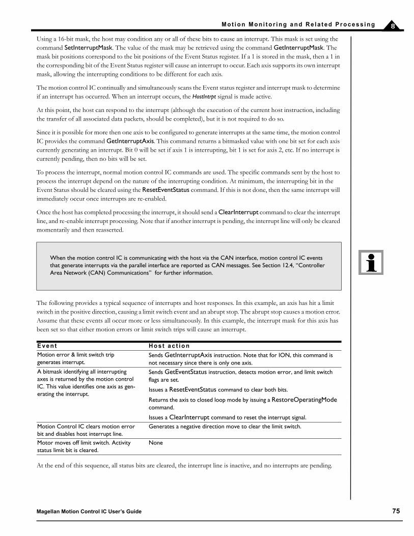
M o t i o n M o n i t o r i n g a n d R e l a t e d P r o c e s s i n g 8
Using a 16-bit mask, the host may condition any or all of these bits to cause an interrupt. This mask is set using the command SetInterruptMask. The value of the mask may be retrieved using the command GetInterruptMask. The mask bit positions correspond to the bit positions of the Event Status register. If a 1 is stored in the mask, then a 1 in the corresponding bit of the Event Status register will cause an interrupt to occur. Each axis supports its own interrupt mask, allowing the interrupting conditions to be different for each axis.
The motion control IC continually and simultaneously scans the Event status register and interrupt mask to determine if an interrupt has occurred. When an interrupt occurs, the HostIntrpt signal is made active.
At this point, the host can respond to the interrupt (although the execution of the current host instruction, including the transfer of all associated data packets, should be completed), but it is not required to do so.
Since it is possible for more then one axis to be configured to generate interrupts at the same time, the motion control IC provides the command GetInterruptAxis. This command returns a bitmasked value with one bit set for each axis currently generating an interrupt. Bit 0 will be set if axis 1 is interrupting, bit 1 is set for axis 2, etc. If no interrupt is currently pending, then no bits will be set.
To process the interrupt, normal motion control IC commands are used. The specific commands sent by the host to process the interrupt depend on the nature of the interrupting condition. At minimum, the interrupting bit in the Event Status should be cleared using the ResetEventStatus command. If this is not done, then the same interrupt will immediately occur once interrupts are re-enabled.
Once the host has completed processing the interrupt, it should send a ClearInterrupt command to clear the interrupt line, and re-enable interrupt processing. Note that if another interrupt is pending, the interrupt line will only be cleared momentarily and then reasserted.
The following provides a typical sequence of interrupts and host responses. In this example, an axis has hit a limit switch in the positive direction, causing a limit switch event and an abrupt stop. The abrupt stop causes a motion error. Assume that these events all occur more or less simultaneously. In this example, the interrupt mask for this axis has been set so that either motion errors or limit switch trips will cause an interrupt.
At the end of this sequence, all status bits are cleared, the interrupt line is inactive, and no interrupts are pending.
When the motion control IC is communicating with the host via the CAN interface, motion control IC events that generate interrupts via the parallel interface are reported as CAN messages. See Section 12.4, “Controller Area Network (CAN) Communications” for further information.
E v e n t H o s t a c t i o n
Motion error & limit switch trip generates interrupt.
Sends GetInterruptAxis instruction. Note that for ION, this command is not necessary since there is only one axis.
A bitmask identifying all interrupting axes is returned by the motion control IC. This value identifies one axis as gen-erating the interrupt.
Sends GetEventStatus instruction, detects motion error, and limit switch flags are set.
Issues a ResetEventStatus command to clear both bits.
Returns the axis to closed loop mode by issuing a RestoreOperatingMode command.
Issues a ClearInterrupt command to reset the interrupt signal.
Motion Control IC clears motion error bit and disables host interrupt line.
Generates a negative direction move to clear the limit switch.
Motor moves off limit switch. Activity status limit bit is cleared.
None
Magellan Motion Control IC User’s Guide 75

M o t i o n M o n i t o r i n g a n d R e l a t e d P r o c e s s i n g8
This page intentionally left blank.
76 Magellan Motion Control IC User’s Guide

9
9 . H a r d w a r e S i g n a l sIn This ChapterThe AxisOut PinThe AxisIn PinAnalog InputThe Synch Pin–Multiple Chip Synchronization
There are a number of signals that may be used to coordinate motion control IC activity with events outside the motioncontrol IC, card, or module. In this section, these signals will be discussed.
9 . 1 T h e A x i s O u t P i n
Each axis has a general purpose axis output pin which can be programmed to track the state of any of the assigned bitsin the Event Status, Activity Status, Drive Status, or Signal Status registers. One or more bits can be output using aselection mask, and their senses can be programmed using a sense mask. The command SetAxisOutMask is used toprogram these conditions, and the command GetAxisOutMask retrieves the programmed values.
The tracked bit(s) in one of these registers may be in the same axis or in a different axis as the axis of the AxisOut signalitself. This function is useful for triggering external peripherals by outputting hardware signals. For example, it allowsthe AxisOut signal to be driven when conditions such as “Drive AxisOut when motion complete bit is low, or whencommutation error bit is high” occur. Whether AxisOut drives the signal with a high or low signal can be controlled usingthe command SetSignalSense.
It is possible to use the AxisOut pin as a software-programmed direct output bit under direct host control. This may bedone by selecting zero as the register in the SetAxisOutMask command, and by adjusting the level of the resultinginactive output state to either high or low by using the SetSignalSense command.
For detailed information on interfacing to this signal, see the Magellan Motion Control IC Electrical Specifications (for motioncontrol IC users), the Magellan Motion Controller Card User’s Guide (for card users), or the ION Digital Drive User’s Manual(for module users).
9 . 2 T h e A x i s I n P i n
Each axis has an input pin (AxisIn signal) that can be used as a general purpose input. This is read using theGetSignalStatus command. It can also be used to trigger automatic events such as performing a motion change (stop,start, change of velocity, etc.) upon a signal transition using breakpoints.
For detailed information on interfacing to this signal, see the Magellan Motion Control IC Electrical Specifications (for motioncontrol IC users), the Magellan Motion Controller Card User’s Guide (for card users), or the ION Digital Drive User’s Manual(for module users).
No special commands are required to set up or enable the AxisIn signals.
Magellan Motion Control IC User’s Guide 77

H a r d w a r e S i g n a l s9
9 . 3 A n a l o g I n p u t
The Magellan Motion Control ICs provide general-purpose analog inputs. The MC58113 provides a single analoginput, while all other MC50000 motion control ICs provide eight inputs. These inputs are connected to internalcircuitry that converts the analog signal to a digital word with a precision of 12 bits for the MC58113 and 10 bits forall other Magellan motion control ICs.
To read the most recent value converted by any of the analog channels, the command ReadAnalog is used. The valuereturned by this command is the result of shifting the converted value to the left into the highest bit position. Theseanalog inputs are general-purpose and are not used by the motion control IC in any calculations.
For detailed information on interfacing to these signals, see the Magellan Motion Control IC Electrical Specifications (formotion control IC users), or Magellan Motion Controller Card User’s Guide (for card users).
9 . 4 T h e S y n c h P i n — M u l t i p l e C h i p S y n c h r o n i z a t i o n
(MC58000 only)
The Magellan Motion Control ICs contain support for synchronizing their internal cycle time across multiple motioncontrol ICs. This allows the start/stop and modification of motion profiles to be synchronized across more than onemotion control IC when precise timing of movement is required. This may be necessary because the motion controlICs are remotely located, or the application may require greater than four axes of synchronized motion. In the mostcommon configuration, one motion control IC is assigned as a master node, and the other motion control ICs are setinto slave mode.
Other configurations, however, are also possible, including using an external hardware device to generate timingsignals for all motion control ICs that are set to slave mode. Alternatively, it is possible to use the signals from themaster motion control IC to synchronize external user hardware.
When an axis is run in slave mode, the cycle time is explicitly controlled by the master, as are external parallel-wordposition encoder reads. Communications and PWM generation are not affected, however.
The input/output state of the Synch pin and its function are set using the command SetSynchronizationMode. Themodes are summarized in the following table.
Upon sending the SetSynchronizationMode command with a mode setting of master or slave the motion control IC’sTime Register is set to 0. This is useful to ensure that all synch-connected Magellans have the same value for the timeregister.
Multi-chip synchronization is not available if any axis is configured for a Pulse & Direction motor type. Therefore synchronization is not available with the MC55000 motion control IC.
E n c o d i n g Mo d e D e s c r i p t i o n
0 Disabled In the disabled mode, the pin is configured as an input and is not used. This is the default mode after reset or power-up.
1 Master In the master mode, the pin outputs a synchronization pulse that may be used by slave nodes or by other devices to synchronize with the internal chip cycle of the master node.
2 Slave In the slave mode, the pin is configured as an input, and a pulse on the pin synchronizes the internal chip cycle.
78 Magellan Motion Control IC User’s Guide

H a r d w a r e S i g n a l s 9
For detailed information on interfacing to these signals, see the Magellan Motion Control IC Electrical Specifications (motioncontrol IC users) or Magellan Motion Controller Card User’s Guide (card users).
When synchronizing multiple motion control ICs, the following rules must be observed:
All motion control ICs must have their sample time set to the same value. For example, if an MC58420 and MC58220 are to be synchronized, the sample time must be at least equal to the greater of the two sample times. See Section 3.4, “Setting the Cycle Time,” for details on the motion control IC cycle time.
Only one node in the network may be a master. For example, with three motion control ICs in a network, one motion control IC must be designated the master and the other two must be slaves.
Slave nodes must be set into slave mode before the master is set. This ensures that the slave(s) cycle starts at precisely the moment that the master assumes its state as master.
Example:
A typical startup sequence to ensure that multiple Magellans are synchronized and that their time registors are all equal is to set all of the synch-connected Magellans to slave mode and then to set one of them as the master.
Magellan Motion Control IC User’s Guide 79

H a r d w a r e S i g n a l s9
This page intentionally left blank.
80 Magellan Motion Control IC User’s Guide

10
1 0 . E n c o d e r I n t e r f a c i n gIn This ChapterIncremental Encoder InputHigh-Speed Position CaptureParallel-Word Position Input
All Magellan Motion Control ICs provide incremental quadrature encoder input, while the MC50000 processors (except the MC58113) also provide parallel-word feedback, which allows devices such A/D (Analog to Digital) converters, R/D (resolver to digital) converters, parallel encoders, and other devices to be used as the motor position source. In addition, ION/CME, ION 3000, and MC58113 ICs can select an input encoding format of pulse and direction for the auxiliary axis which is useful when operating with a motion controller that outputs pulse and direction signals. See Section 4.5 “Electronic Gear Profile,” for more information on using pulse and direction as a command input.
To set the feedback type, the command SetEncoderSource is used. This value can be read using the command GetEncoderSource.
1 0 . 1 I n c r e m e n ta l E n c o d e r I n p u t
Incremental encoder feedback provides two square-wave signals: A quadrature and B quadrature. There is also an optional index pulse, which indicates when the motor has made one full rotation. The A and B signals are offset from each other by 90°, as shown in Figure 10-1.
For the quadrature incremental position to be properly registered by the motion control IC with the motor moving in the positive direction, QuadA should lead QuadB. When the motor moves in the negative direction, QuadB should lead QuadA. Due to the 90° offset, four resolved quadrature counts occur for one full phase of each A and B channel.
Figure 10-1: Quadrature Encoder Timing
(= ~QuadA * ~QuadB * ~Index)Index
Quad A
Quad B
~Index
Magellan Motion Control IC User’s Guide 81

E n c o d e r I n t e r f a c i n g10
1 0 . 1 . 1 A c t u a l P o s i t i o n R e g i s t e r
The motion control IC continually monitors the position feedback signals, and accumulates a 32-bit position value called the actual position. At power-up, the default actual position is zero. The actual position can be set with one of two commands: SetActualPosition, and AdjustActualPosition. The current actual position can be retrieved using the command GetActualPosition.
SetActualPosition sets the position to an absolute specified 32-bit value. Particularly when using incremental feedback, the actual position is generally set shortly after power-up, using a homing procedure to reference the actual position to a physical hardware location. AdjustActualPosition changes the current actual position by a signed relative value. For example a value of –25 specified using this command will subtract 25 from the current actual position.
In addition to retrieving the actual axis position, it is also possible to retrieve an estimation for the instantaneous velocity of the axis. This is accomplished using the command GetActualVelocity. Note that the provided velocity is an estimated quantity, created by subtracting the current position from the previous cycle’s position. It is therefore subject to jitter or noise, particularly at low velocity.
1 0 . 1 . 2 D i g i ta l F i l t e r i n g
All encoder inputs, as well as both the index and home capture inputs, are digitally filtered to enhance reliability. The filter requires that a valid transition be accepted only if it remains in its new (high or low) state for a specified amount of time. This ensures that brief noise pulses will not be interpreted as an encoder transition. See the Magellan electrical specifications for your motion control IC for detailed information
Although this digital filtering scheme can increase the overall reliability of the quadrature data, to achieve the highest possible reliability, additional external signal prcoessing techniques may be required. Techniques such as differential line drivers/receivers, or analog filtering have been proven in this area. Whether these additional schemes are required depends on the specific system, and the amount and type of noise sources.
1 0 . 2 H i g h - Sp e e d P o s i t i o n C a p t u r e
Each axis of the Magellan Motion Control ICs supports a high-speed Position Capture register that allows the current axis location (as determined by an attached encoder) to be captured when triggered by an external signal. For MC50000 motion control ICs, two signals may be used as the capture trigger: the Index signal or the Home signal. For ION, there is an additional available input source called HighSpeedCapture.
These input triggers differ in how a capture is recognized. For all products except the MC58110, MC55110, and MC58113 when the Index signal is used as the trigger, a capture will be triggered when the A, B, and Index signals achieve a particular state (defined by the Signal Sense register using the SetSignalSense command). If the Home or HighSpeedCapture signal is selected as the capture trigger source, then only that signal need be in a particular state for the capture to be triggered. For the single chip motion control ICs (MC5x110), the Index operates like the Home or HighSpeedCapture.
For MC58113 the capture qualification scheme is somehwat different than for other Magellan ICs. See the MC58113 Electrical Specifications for details.
P r o d u c t Av a i l a b l e p o s i t i o n c a p t u r e s i g n a l t r i g g e r s
MC50000 IndexHome
ION IndexHomeHighSpeedCapture
82 Magellan Motion Control IC User’s Guide

E n c o d e r I n t e r f a c i n g 10
The command SetCaptureSource determines whether the Index signal, the Home signal, or the HighSpeedCapture signal will be used as the position capture trigger. The command GetCaptureSource retrieves this same value. When Index is selected as the trigger source, use the Index bit in the Signal Sense register to set the trigger state. When either Home or HighSpeedCapture are selected as the trigger source, use the Capture bit to set the trigger state.
When a capture is triggered, the contents of the Actual Position registers (derived from an attached encoder) are transferred to the Position Capture register, and the capture-received indicator (bit 3 of the Event Status register) is set. To read the Capture register, the command GetCaptureValue is used. The Capture register must be read before another capture can take place. Reading the Position Capture register causes the trigger to be re-armed, allowing for more captures to occur. As for all Event Status register bits, the Position Capture indicator may be cleared by using the command ResetEventStatus.
1 0 . 3 P a r a l l e l - Wo r d P o s i t i o n I n p u t
(MC50000 except MC58113-series only)
For feedback systems that do not provide incremental signals, but instead use a digital binary word, Magellan supports a parallel-word input mechanism that can be used with a large variety of devices including resolvers (after resolver to digital conversion), absolute optical encoders, laser interferometers with parallel word read-out, incremental encoders with external quadrature decoder circuit, and A/D converters reading an analog feedback signal.
In this position-input mode, the encoder position is read through the motion control IC’s external bus by reading a 16-bit word. One word is read for each axis set to this mode. Depending on the nature of the feedback device, fewer than 16 bits of resolution may be available, in which case the unused high order data bits should be arranged to indicate a 0 value when read by the motion control IC. It is also acceptable to sign-extend these bits. Under no circumstances should unused bits of the parallel-word be left floating.
The value input by the motion control IC should be binary coded. The Magellan Motion Control ICs assume that the position data provided by the external device is a two's complemented signed number. If the value returned ranges
from 0 to 2n–1 (where n is the number of bits provided by the feedback device), then the difference in behavior will be the interpretation of the start location. This will be shifted by one-half of the full scale feedback range. If desired, this initial position may be altered using the SetActualPosition command.
When the encoder source is set to parallel, the first value read from the external bus is assumed to be an absolute position, and is directly stored in the Actual Position register.
1 0 . 3 . 1 M u l t i - Tu r n S y s t e m s
In addition to supporting position tracking across the full numeric feedback range of a particular device, the ability to support multi-turn systems is also provided. The parallel encoder values are continuously examined, and a position wrap condition is automatically recognized. This ranges from the largest encoder value to the smallest encoder value (negative wrap), or from smallest value to largest value (positive wrap).
Using this virtual multi-turn counter, the Magellan Motion Control ICs continuously maintain the axis location to a full 32-bit value. If the axis does not wrap around (non multi-turn system), the range will stay within a 16-bit value.
As the motor moves in the positive direction, the input value should increase to a maximum value, at which point it may wrap back to zero and continue increasing from there. Likewise, when the motor moves in the negative direction, the value should decrease to zero, at which point it may wrap back to its maximum. The value at which the parallel input device wraps is called the device’s modulus, and should be set using the SetEncoderModulus command. Note that the SetEncoderModulus command takes as a parameter one-half of the value of the modulus.
Magellan Motion Control IC User’s Guide 83

E n c o d e r I n t e r f a c i n g10
For example, if a rotary motor uses a 12-bit resolver for feedback, the encoder modulus is 4,096 and therefore, the value sent to the SetEncoderModulus command would be 2,048. Once this is done, then each time the motor rotates and the binary word value jumps from the largest binary output to the smallest, the Magellan Motion Control IC will properly recognize the motor wrap condition, and accumulate actual encoder position with values larger than 4,096 or smaller than 0.
For systems using a position counter with a modulo smaller than the encoder counts per revolution, set the counts/rev value equal to the position counter size. For example, if a rotary laser interferometer is being used that provides a
16-bit output value, but provides 16,777,216 counts per revolution, use a counts/rev value of 32,768 (216/2).
The encoder modulus should always be set prior to setting the encoder source to parallel.
1 0 . 3 . 2 P a r a l l e l - W o r d D e v i c e I n t e r f a c i n g
For each axis set for parallel-word input, the motion control IC will use its peripheral bus to read the position feedback value for that axis. The motion control IC will perform a peripheral read at the corresponding address, but axes not in parallel-word mode will not be addressed. This read occurs every 50µs. See the Magellan Control IC Electrical Specification for details on parallel-word addresses and interfacing.
Motion cards such as Prodigy-PCI and Prodigy-PC/104 do not directly provide the ability to connect parallel-word encoder devices; however, it is possible to purchase or construct a daughter card that plugs into the main motion card and supports this interface.
No high-speed position capture is supported in the parallel-word device input mode. Therefore the Index and Home signals, as well as the QuadA and QuadB signals are unused.
84 Magellan Motion Control IC User’s Guide

11
11 . M o t o r O u t p u tIn This ChapterDisabling the Motor Output Module Enabling the Motor Output Module Motor Type Motor Command Output Setting PWM Frequency Setting PWM Signal Interpretation (MC58113-Series Only)Multi-Phase Motor Interfacing Microstepping Motor Output DC Servo Motor OutputPulse & Direction Signal Generation
Magellan Motion Control ICs contain a motor output module to control how motor command signals are generated and output to the amplifier. For MC50000, these signals are output through the motion control IC and are used to interface to external circuitry. For ION, these signals remain internal to the drive. This chapter will detail how to enable and disable the motor output module, how to select a motor type, and how to select and interface to different amplifier signaling techniques.
11 . 1 D i s a b l i n g t h e M o t o r O u t p u t M o d u l e
There are a number of reasons why it might be desirable to disable the motor output module. See Section 3.2, “Enabling and Disabling Control Modules,” for an overall discussion of module enabling and disabling. In particular, the motor output module is generally disabled for safety-related condition, or for system calibration. To disable the motor output module the command SetOperatingMode is used. The value set using this command can be read using GetOperatingMode.
If the motor output module is disabled, a “zero” command will be sent to the motor, or to each phase of the motor for multi-phase motors such as brushless DC or microstepping motors. Depending on the motor output signal format, this zero command will be represented in different ways. See the subsequent sections of this chapter for more information on motor output signal representation.
Note that disabling the motor output module may or may not immediately stop the motor. Disabling this module has the effect of “free-wheeling” the motor, which means the motor may stop, coast, or even accelerate (if a constant external force exists such as on a vertical axis) depending on the load, inertia, and configuration of the axis mechanics.
Magellan Motion Control IC User’s Guide 85
M o t o r O u t p u t11
For MC50000 except MC58113 or when the OutputMode0 pin is tied low, the default condition of the motor output module is enabled.
11 . 2 E n a b l i n g t h e M o t o r O u t p u t M o d u l e
A previously disabled motor output module may be re-enabled in a number of ways. If the module was disabled using the SetOperatingMode command, then another SetOperatingMode command may be issued. If this module was disabled as part of an automatic event-related action (see Section 8.1, “SetEventAction Processing,” for more information), then the command RestoreOperatingMode is used.
Regardless of how the module is re-enabled, at the time that the reenable operation is requested, the desired motor commands for each phase of the motor will immediately be output to the amplifier. Care should therefore be taken to re-enable this module when the axis is in a stable condition, such that no abrupt motion occurs. Along these lines, it is recommended that if additional modules are to be enabled such as the current loop, the position loop, and the trajectory generator, all modules be enabled at the same time, thereby insuring that internal current loop or position loop values (such as integrators) will be zeroed at the time of enabling.
11 . 3 M o t o r Ty p e
Magellan Motion Control ICs provide support for a number of motor types including DC brush, brushless DC and step motors. In addition, in the case of Brushless DC and microstepping motors, both two and three phase motors are supported for some products. The following table shows this.
For products such as ION or the MC51113, MC53113, or MC54113 ICs, which support one motor type, selection of the correct motor type is not necessary since the motor type is already set to its default condition. For products such as MC58000 motion control ICs or MC58000-based cards, the motor type for each axis must be selected, and this value is used to determine a number of default operating conditions such as which control modules are enabled and the default amplifier interface format.
For ION modules, MC58113-series ICs, and Atlas-connected axes the default condition is disabled, therefore to begin drive operations, a SetOperatingMode command must be sent to enable the motor output module.
P r o d u c t M o t o r Ty p e s S u p p o r t e d
MC58000 ICs except MC58113 DC brushBrushless DC, 2-phaseBrushless DC, 3-phaseMicrostepping, 2-phaseMicrostepping, 3-phaseStep
MC55000 ICs Step motorMC58113 IC DC brush
Brushless DC, 3-phaseMicrostepping, 2-phase
ION (DC brush), MC51113 IC DC brushION (brushless DC), MC53113 IC Brushless DC, 3-phaseION (microstepping), MC54113 IC Microstepping, 2-phase
86 Magellan Motion Control IC User’s Guide

M o t o r O u t p u t 11
For Atlas-connected axes, the motor type must still be specified, and care should be taken to insure that the selected motor type matches the motor type of the Atlas connected to that axis. Selected motor types should be either DC brush, brushless DC 3-phase, or step.
During powerup, the Magellan processors except MC58113 read a motor configuration word at a specific memory address on its external bus to determine the default motor type setting for each axis. For motion control IC designs, see the Magellan Motion Control IC Electrical Specifications for more details. For MC58000-based cards, such as PMD’s Prodigy cards, the logic used to respond to this read operation accesses on-card user-specified DIP switches, or is stored in NVRAM configuration memory. Consult the User’s Guide for the PMD-based card product you are using for more information. The MC58113 allows internal NVRAM storage of startup parameters such as motor type. See the MC58113 Electrical Specifications for more information.
The value of the motor type read during powerup can also be set at a later time via the command SetMotorType. The value set can be read back using the command GetMotorType. If the motor type is to be set by the user in this way, the motor type should be sent first if a series of commands are to be used to configure the output method and amplifier interface format. See the Magellan Motion Control IC Programmer’s Command Reference for more information.
11 . 4 M o t o r C o m m a n d O u t p u t
In addition to selection of the motor type, to correctly interface to an amplifier or amplifier circuit, the motor command output format must be chosen. The Magellan Motion Control ICs provide a variety of methods to generate signals used to interface to the motor amplifier; however, the methods available vary with each product series. The following table shows the motor output options available for each supported motor type and motion control IC. For ION products, the motor amplifier is located internally, and the motor command output format need not be selected.
M a g e l l a n Mo t o r Ty p eP h a s e s p e r A x i s Av a i l a b l e O u t p u t f o r m a ts
MC58000 DC brush 1 SPI Atlas
Sign/magnitude PWM
50/50 PWM
PWM High/Low (MC58113 only)
Parallel DAC - offset binary* (except MC58113)
Parallel DAC - sign magnitude (except MC58113)
SPI DAC - offset binary
SPI DAC - two’s complementMC58000 Brushless DC 2 or 3 SPI Atlas
Sign/magnitude PWM**
50/50 PWM
PWM High/Low (MC58113 only)
Parallel DAC - offset binary* (except MC58113)
Parallel DAC - sign magnitude (except MC58113)MC58000 Microstepping 2 or 3 Sign/magnitude PWM**
50/50 PWM
PWM High/Low (MC58113 only)
Parallel DAC - offset binary* (except MC58113)
Parallel DAC - sign magnitude (except MC58113)MC58000 Step N/A SPI Atlas
Pulse and DirectionMC55000 Step N/A Pulse and DirectionION All (DC Servo, brushless DC,
microstepping)Not applicable. Amplifier is internal. No motor command signal output through hardware.
Magellan Motion Control IC User’s Guide 87

M o t o r O u t p u t11
* Card products provide analog output +/-10V using the parallel DAC - offset binary output mode.** Only when 2-phases are selected. This format is not supported for 3-phase motors.
PWM High/Low, Sign/magnitude PWM, 50/50 PWM, parallel DAC, and SPI DAC all output a signed numerical motor command value while using different signal formats. Each of these signal formats encodes this signed numerical value, which represents the torque at which the motion control IC is commanding the motor.
SPI Atlas selects the four-signal Atlas SPI interface. This signal format encodes a complete bi-directional protocol that allows the Magellan to send torque commands as well as interact with Atlas’s other control features and status registers. For more information on Atlas Amplifiers see Section 11.4.8, “SPI Atlas,” as well as the Atlas Digital Amplifier User’s Manual.
Pulse and direction is fundamentally different from the other output formats, because it makes no attempt to encode a motor torque. Instead, pulse and direction interfaces directly with step motor amplifiers which accept this format. It should be noted that pulse and direction is generally used to drive step motors, but can also be used with servo motors for amplifiers designed with this capability.
Choice of output mode generally determines the nature of the amplifier you will use. PWM output formats are most commonly used with IC-based switching circuits. Analog output formats such as parallel DAC or SPI DAC are most often used to generate a +/10V signal which is then connected to an external analog input amplifier. SPI Atlas is exclusively used to connect to PMD’s Atlas Amplifiers
The command SetOutputMode controls which of the available output formats will be used. The command GetOutputMode retrieves this value.
In the next several sections we will look at each of these motor command output formats in more detail.
11 . 4 . 1 S i g n / M a g n i t u d e P W M
In sign/magnitude PWM mode, two pins are used to output the motor command information for each motor phase. One pin carries the PWM magnitude, which ranges from 0 to 100%. This signal expresses the absolute magnitude of the desired motor command. A high signal on this pin means the motor coil should be driven with voltage. A second pin outputs the sign of the motor command by going high for positive sign, and low for negative.
For example, if the PWM resolution is one part per 2,048 and the motor commands that the motion control IC output for a given phase is +12,345, then the sign bit will be output as a high level, and the magnitude pin will output with a duty cycle of 2,048*12,345/32,768 = 771.56 = 772. This indicates that the magnitude signal will be high for 772 cycles, and low for the remaining 1,276 cycles. If it were desired that the output value be –12,345, then the magnitude signal would be the same, but the sign bit would be low instead of high.
Sign/magnitude PWM output is typically used with H-bridge type amplifiers. Most amplifiers of this type have separate sign and magnitude inputs, which allows the Magellan signals to be connected directly.
88 Magellan Motion Control IC User’s Guide

M o t o r O u t p u t 11
11 . 4 . 2 5 0 / 5 0 P W M
In 50/50 PWM mode, only one pin is used per motor output or per motor phase. This pin carries a variable duty cycle PWM signal, much like the magnitude signal for sign magnitude PWM. This PWM output method differs in that a 50% output signal (high half the time, low half the time) indicates a desired motor command of zero. Positive motor commands are encoded as duty cycles greater than 50% duty cycles, and negative motor commands are encoded as duty cycles less than 50%. In this mode, a full-on positive command is encoded as a 100% duty cycle (always high), and a full on negative command is encoded as a 0% duty cycle (always low).
For example, if the PWM resolution is one part per 2,048 and the motor commands that the motion control IC outputs for a given phase is +12,345, then the magnitude pin will output with a duty cycle of 1,024 + 1,024*12,345/32,768 = 771.56 = 1,409.78 = 1,410. This indicates that the magnitude signal will be high for 1,410 cycles, and low for the remaining 638 cycles. If it were desired that the output value be –12,345, then the magnitude signal would have a duty cycle of 1,024 + 1,024*–12,345/32,768 = 638.2 = 638; indicating that the magnitude signal will be high for 638 cycles, and low for the remaining 1,410.
50/50 PWM output is used with two different types of amplifiers. When driving a brushless PM (permanent magnet) motor, the magnitude signal is connected to a half-bridge driver. When driving a DC brushed motor, an H-bridge type amplifier is used. The magnitude signal of the H-bridge is always turned on, and the magnitude output of the motion control IC is connected to the sign input of the H-bridge. This alternative method of controlling an H-bridge is useful in situations where motor back-EMF during deceleration is a problem using the standard sign magnitude schemes.
Figure 11-2 illustrates 50/50 PWM output encoding.
0 / 1024(zero command)
1 / 1024(minimum
command)
1
0
1
0
512 / 1024(50% command)
1023 / 1024(maximum command)
1024 / 1024(100% command)
1
01
0
1
0
Figure 11-1: Sign/Magnitude PWM Encoding
Magellan Motion Control IC User’s Guide 89
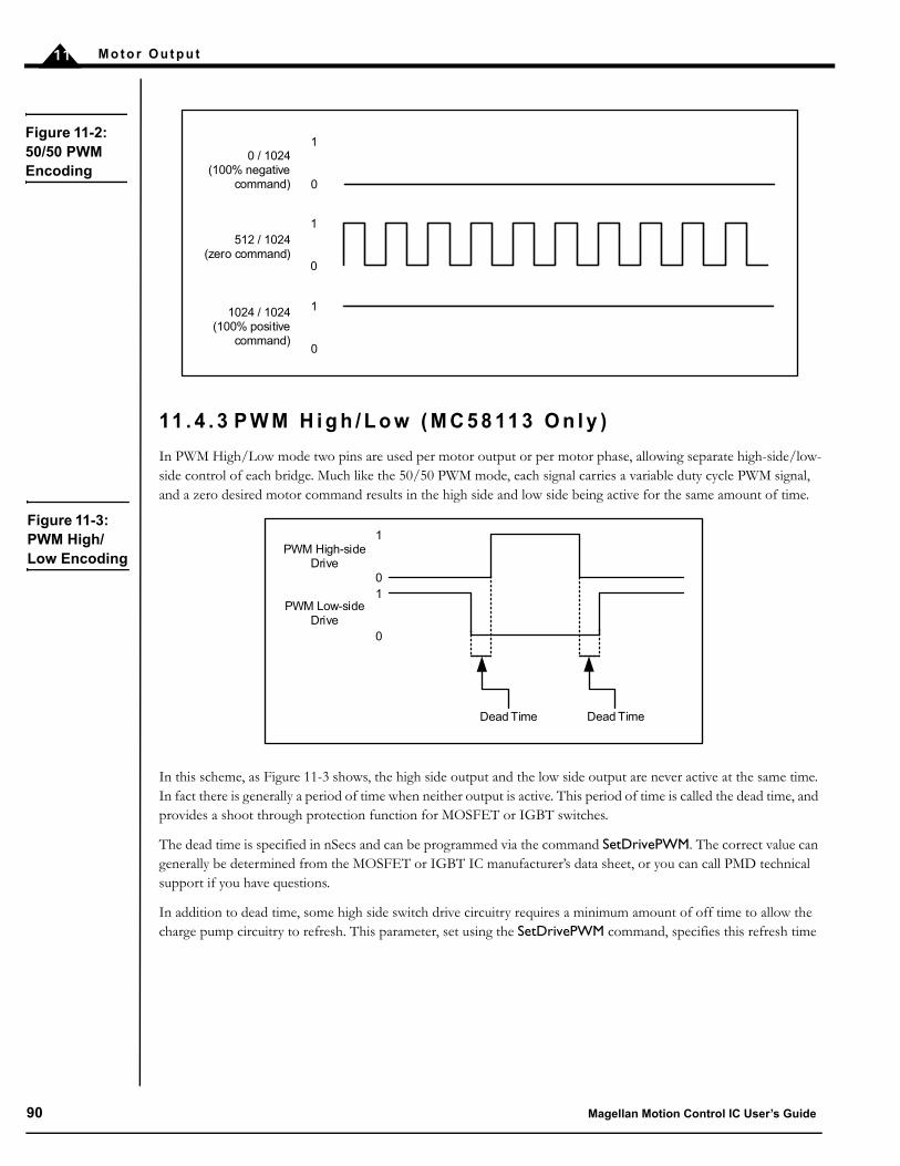
M o t o r O u t p u t11
11 . 4 . 3 P W M H i g h / L o w ( M C 5 8 11 3 O n l y )
In PWM High/Low mode two pins are used per motor output or per motor phase, allowing separate high-side/low-side control of each bridge. Much like the 50/50 PWM mode, each signal carries a variable duty cycle PWM signal, and a zero desired motor command results in the high side and low side being active for the same amount of time.
In this scheme, as Figure 11-3 shows, the high side output and the low side output are never active at the same time. In fact there is generally a period of time when neither output is active. This period of time is called the dead time, and provides a shoot through protection function for MOSFET or IGBT switches.
The dead time is specified in nSecs and can be programmed via the command SetDrivePWM. The correct value can generally be determined from the MOSFET or IGBT IC manufacturer’s data sheet, or you can call PMD technical support if you have questions.
In addition to dead time, some high side switch drive circuitry requires a minimum amount of off time to allow the charge pump circuitry to refresh. This parameter, set using the SetDrivePWM command, specifies this refresh time
0 / 1024(100% negative
command)
1
0
512 / 1024(zero command)
1024 / 1024(100% positive
command)
1
0
1
0
Figure 11-2: 50/50 PWM Encoding
Figure 11-3: PWM High/Low Encoding
Dead Time
PWM High-sideDrive
PWM Low-sideDrive
1
01
0
Dead Time
90 Magellan Motion Control IC User’s Guide

M o t o r O u t p u t 11
and has units of nSecs. The related parameter of refresh time period, which is the time interval between these off time refreshes, and which is also set using the SetDrivePWM command, has units of current loop cycles.
PWM High/Low output mode is used with discrete component bridge designs or with integrated half bridge and H-bridge drivers ICs that provide this level of control input. The overall bridge configuration is the same as that for PWM 50/50; A triple half bridge configuration for three-phase Brushless DC, a single H-bridge for DC Brush motor drive, and two H-bridges for two-phase step motor drive.
PWM High/Low is the most commonly used mode when the MC58113’s active current control is used, although PWM 50/50 can also be used with current control active.
11 . 4 . 4 P a r a l l e l D A C - O f f s e t B i n a r y
In parallel DAC - offset binary mode, the motor command for a given phase is output directly to the motion control IC's peripheral bus where it is assembled into an analog voltage using a DAC (Digital to Analog Converter). The motion control IC chip writes the DAC output value to each enabled channel in this mode at the commutation frequency of 10 kHz. For example, on an MC58420 with all four axes set to parallel DAC mode, DAC output will be written for each axis once per 100 µsec, with the writes in pairs separated by 50 µsec.
For one- or two-phase motors, one DAC output is used for each phase. For three-phase motors, only two DAC outputs are used. The third phase will always be an analog signal equal to –1 * (P1 + P2), where P1 is the output for phase 1, and P2 is the output for phase 2. If necessary, this third phase signal may be realized using an inverting summing amplifier in the external circuitry. Generally this is not necessary, since the majority of three-phase off-the-shelf amplifiers accept two phases and internally construct the third. The written output value has a 16-bit resolution. This value is offset by 8000h, so a value of 0 will correspond to the most negative output. A value of 8000h corresponds to zero output, and a value of FFFFh corresponds to the most positive output.
DACs with resolutions lower than 16-bit may be used. In this case, output values must be scaled to the high-order bits of the 16-bit data word. For example, to connect to an 8-bit DAC, pins Data8–15 are used. The contents of the low-order 8 bits (Data0–7) are transferred to the data bus, but are ignored.
The motion control IC writes the DAC values using the external peripheral bus described in the Magellan Motion Control IC Electrical Specifications.
For more information on DAC signal timing and conditions, see the DAC pin descriptions and peripheral write interface timing diagram in the Magellan Motion Control IC Electrical Specifications document for your motion control IC.
If using a Magellan-based card, all interfacing circuitry and decoding are handled by the card, and a direct analog +/– 10V for each desired output phase will be provided through a connector. To interface to the signals, see the Magellan Motion Controller Card User’s Guide.
11 . 4 . 5 P a r a l l e l D A C - S i g n M a g n i t u d e
Parallel DAC - sign magnitude mode is very similar to parallel DAC - offset binary mode, however the encoding of the 16-bit word sent to each DAC channel has a different format. As indicated in the previous section, in offset binary mode the number output is a 16-bit two’s complemented representation of the desired motor or phase command shifted by a value of 8000h. In sign magnitude mode, the encoding is different. In this format the representation is split into a 1 bit sign field and a 15 bit magnitude field.
The default values for dead time, refresh time, and refresh period are set to be maximally safe but are not appro-riate to drive typical switching hardware. For proper amplifier function these values must be set with values ap-propriate for the connected switching circuitry.
Magellan Motion Control IC User’s Guide 91

M o t o r O u t p u t11
This is encoded as follows: the top bit (bit 15) of the output DAC word represents the sign, with a 1 value indicating a negative output signal, and a 0 value indicating a positive output value. The low 15 bits (DAC outputs 0–14) encode an unsigned 15-bit magnitude of the desired motor or phase command. For example, in this scheme, the most negative possible command (–32,767) is encoded as a FFFFh, a zero output value is encoded as 0, and the most positive possible output value (+32,767) is encoded as 7FFFh.
In all other respects, this mode is identical to offset binary mode, and all other comments in the section above for that mode apply to parallel DAC - sign magnitude mode.
11 . 4 . 6 S P I D A C - O f f s e t B i n a r y
In SPI DAC mode, single-phase drive data for DC brush motors (or brushless DC motors with external commutation) is output using the motion control IC’s SPI (Serial Peripheral Interface) output port. The Magellan SPI output is a high-speed, synchronous serial I/O port that allows a serial bit stream of 16-bit data words to be shifted out of the motion control IC at a 8 Mbps rate. The SetSPIMode command controls the four possible output clocking schemes via the mode parameter as described in the following table.
The output value is offset by 8000h, so a value of 0 will correspond to the most negative output. A value of 8000h corresponds to zero output, and a value of FFFFh corresponds to the most positive output.
Drive data for each axis is interleaved on the single SPI output pin. When the SPI data for an axis is being output, the corresponding SPIEnable line (SPIEnable for single-axis configurations, SPIEnable1 – SPIEnable4 for multiple axis configurations) is active; at all other times it is inactive. Note that some Magellan Motion ICs allow the SPIEnable signal sense to be user-programmed. See Section 7.5.1, “Signal Sense Mask,” for details.
11 . 4 . 7 S P I D A C - Tw o ’s C o m p l e m e n t
This mode is identical to the SPI DAC - offset binary mode described above except for the format of the output value. In this mode, the value is in standard two’s complement format where zero (0) corresponds to zero output, 7FFFh corresponds to the most positive output and 8000h corresponds to the most negative output.
In all other respects, this mode is identical to offset binary mode, and all other comments in the section above for that mode apply to SPI DAC - two’s complement mode.
For Magellan cards, sign magnitude mode may not be used. Parallel DAC - offset binary mode must be selected for +/– 10V analog output.
S e t S P I M o d e s e t t i n g D e s c r i p t i o n
RisingEdge Rising edge without phase delay: the SPIClock signal is active low. The SPIXmt pin trans-mits data on the rising edge of the SPIClock signal.
RisingEdgeDelay Rising edge with phase delay: the SPIClock signal is active low. The SPIXmt pin transmits data one half-cycle ahead of the rising edge of the SPIClock signal.
FallingEdge Falling edge without phase delay: the SPIClock signal is active high. The SPIXmt pin trans-mits data on the falling edge of the SPIClock signal.
FallingEdgeDelay Falling edge with phase delay: the SPIClock signal is active high. The SPIXmt pin transmits data one half-cycle ahead of the falling edge of the SPIClock signal.
92 Magellan Motion Control IC User’s Guide

M o t o r O u t p u t 11
11 . 4 . 8 S P I A t l a s
This mode sets the motor output interface to SPI Atlas. The following section provides a general overview of Magellan/Atlas operations when in this mode, however most users will not need to know these details since all Magellan to Atlas operations are handled automatically by the Magellan Motion Control IC.
Atlas Digital Amplifiers are single-axis devices for torque or voltage-mode control of three-phase brushless DC motors, DC Brush motors, or two-phase step motors. They accept a stream of desired torque or voltage values from the Magellan and perform all current loop processing and switching bridge control to continuously drive the motor coils to the specified, commanded values.
In addition to providing a stream of torque or voltage commands, Magellan sets up operational parameters needed by Atlas such as control gains, safety-related parameters, and other information. These parameters may be provided to Atlas at each power up, or stored non-volatilely on Atlas so that they no longer need to be loaded at each power-up. See the Atlas Digital Amplifier User’s Manual for more information.
Communication to/from Atlas occurs via an SPI interface and associated protocol that uses packet-oriented commands to specify various Atlas parameters, and, if desired, request status information from Atlas. This protocol has been designed for maximum speed and flexibility so that torque or voltage commands can be continuously sent to Atlas even while the external controller queries Atlas for various information. Please refer to the Atlas Digital Amplifier Complete Technical Reference for information on the SPI interface.
At power-up or reset, Atlas checks for the presence of stored configuration information in its non-volatile memory. If no such configuration information is found, default values are used.
SPI Atlas Communications Overview
Atlas uses an SPI (Serial Peripheral Interface) digital connection to communicate with Magellan. This connection is used to setup Atlas parameters, specify voltage or torque output values, monitor Atlas operation, as well as other functions.
Figure 11-4: High Level Magellan To Atlas Connection Diagram
Optional Hall & Encoder Feedback
Hall & Encoder
Atlas®
DigitalAmplifier
Brushless DCDC Brush
Step MotorMC58000
Magellan®
MotionProcessor
SPI
Command Protocol
NVRAM
Magellan Motion Control IC User’s Guide 93

M o t o r O u t p u t11
SPI Atlas uses only 4 signals; SPIClk (Clock), SPIEnable (chip select), SPIRcv (slave in), and SPIXmt (slave out). Atlas utilizes standard SPI signaling and timing control for the hardware interface and implements a higher level protocol on top of this.
All communications to and from Atlas are in the form of a packet. Figure 11-5 shows the overall packet format. All Atlas SPI packets are comprised of a two word header and one or more optional command words. For more information, refer to the Atlas Digital Amplifier User Manual.
11 . 5 S e t t i n g P W M F r e q u e n c y
If using the PWM output mode, under some circumstances, and for some products, the PWM output frequency may be specified using the command SetPWMFrequency. The value set using this command may be retrieved using GetPWMFrequency.
Choice of one of these frequencies over another depends on motor type and application. The default is 20 kHz, which is also the recommended frequency except for very low inductance motors.
For ION, 20kHz is the default PWM rate, and is recommended for most applications. 40kHz may be used effectively with some low-inductance motors.
11 . 6 S e t t i n g P W M S i g n a l I n t e r p r e ta t i o n ( M C 5 8 11 3 - S e r i e s O n l y )
The MC58113 allows output PWM signals to have their active/inactive interpretation programmed, meaning that normally active high PWM switch outputs can be changed to active low. This is accomplished via the SetDrivePWM command.
Note that this command does not affect the sign signal interpretation when motor output mode is set to Sign/Magnitude PWM.
P r o d u c t P W M f r e q u e n c y c h o i c e s
MC50000 20 kHz.40 kHz (MC58113 only)80 kHz.
ION 20 kHz.40 kHz.
Figure 11-5: SPI Atlas Communica-tions Protocol Overview
Controller word 0 x t u 0 Header data 1
Atlas word 0 SPI Status word
15 14 13 12 11 10 9 8 7 6 5 4 3 2 1 0
Controller word 1 Header data 2
Atlas word 1 Atlas checksum Controller checksum
15 14 13 12 11 10 9 8 7 6 5 4 3 2 1 0
Controller word 2-N Optional command
Atlas word 2-N Optional command response
15 14 13 12 11 10 9 8 7 6 5 4 3 2 1 0
94 Magellan Motion Control IC User’s Guide
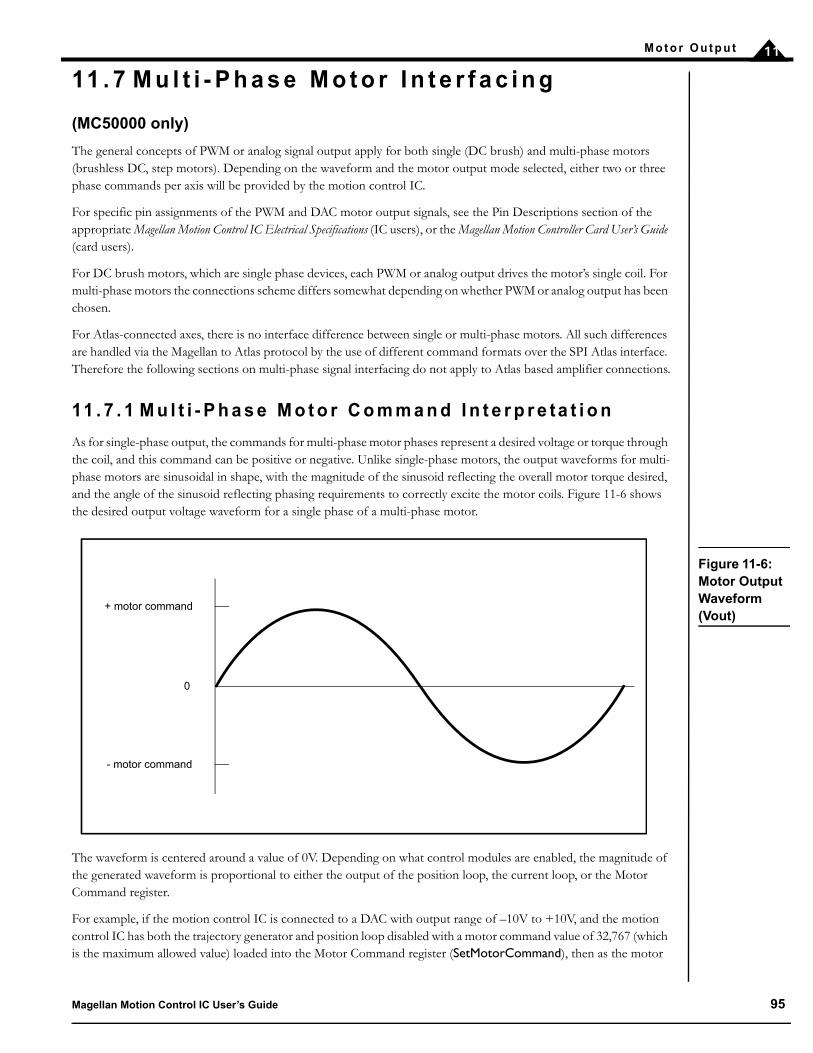
M o t o r O u t p u t 11
11 . 7 M u l t i - P h a s e M o t o r I n t e r f a c i n g
(MC50000 only)
The general concepts of PWM or analog signal output apply for both single (DC brush) and multi-phase motors (brushless DC, step motors). Depending on the waveform and the motor output mode selected, either two or three phase commands per axis will be provided by the motion control IC.
For specific pin assignments of the PWM and DAC motor output signals, see the Pin Descriptions section of the appropriate Magellan Motion Control IC Electrical Specifications (IC users), or the Magellan Motion Controller Card User’s Guide (card users).
For DC brush motors, which are single phase devices, each PWM or analog output drives the motor’s single coil. For multi-phase motors the connections scheme differs somewhat depending on whether PWM or analog output has been chosen.
For Atlas-connected axes, there is no interface difference between single or multi-phase motors. All such differences are handled via the Magellan to Atlas protocol by the use of different command formats over the SPI Atlas interface. Therefore the following sections on multi-phase signal interfacing do not apply to Atlas based amplifier connections.
11 . 7 . 1 M u l t i - P h a s e M o t o r C o m m a n d I n t e r p r e ta t i o n
As for single-phase output, the commands for multi-phase motor phases represent a desired voltage or torque through the coil, and this command can be positive or negative. Unlike single-phase motors, the output waveforms for multi-phase motors are sinusoidal in shape, with the magnitude of the sinusoid reflecting the overall motor torque desired, and the angle of the sinusoid reflecting phasing requirements to correctly excite the motor coils. Figure 11-6 shows the desired output voltage waveform for a single phase of a multi-phase motor.
The waveform is centered around a value of 0V. Depending on what control modules are enabled, the magnitude of the generated waveform is proportional to either the output of the position loop, the current loop, or the Motor Command register.
For example, if the motion control IC is connected to a DAC with output range of –10V to +10V, and the motion control IC has both the trajectory generator and position loop disabled with a motor command value of 32,767 (which is the maximum allowed value) loaded into the Motor Command register (SetMotorCommand), then as the motor
Figure 11-6: Motor Output Waveform (Vout)
0
+ motor command
- motor command
Magellan Motion Control IC User’s Guide 95

M o t o r O u t p u t11
rotates through a full electrical cycle, a sinusoidal waveform centered at 0V will be output with a minimum voltage of –10V and a maximum voltage of +10V.
11 . 7 . 2 B r u s h l e s s D C M o t o r O u t p u t
Figure 11-7 illustrates a typical amplifier configuration for a three-phase brushless motor using PWM High/Low output with current control active. In this configuration the MC58113-series IC outputs six phased PWM magnitude signals per axis and uses three leg current input signals to form a complete bridge controller with high performance current control. See the MC58113 Electrical Specification for more details on this motor drive configuration.
PWMHigh1B
PWMLow1B
Current1B
PWMHigh1A
PWMLow1A
Current1A
PWMHigh1C
PWMLow1C
Current1C
HV
Pre-driverPhase
A
GND
AnalogConditioning
HV
Pre-driverPhase
B
GND
AnalogConditioning HV
Pre-driverPhase
C
GND
AnalogConditioning
MC58113 or
MC53113
Phase A
Phase B
Phase C
Figure 11-7: Brushless DC Motor (PWM High/Low With Current Control) Connection Scheme (MC58113-Series ICs Only)
96 Magellan Motion Control IC User’s Guide

M o t o r O u t p u t 11
Figure 11-8 illustrates a typical amplifier configuration for a three-phase brushless motor using the 50/50 PWM output mode without current control. In this configuration, the motion control IC outputs three phased PWM magnitude signals per axis. These signals are then fed directly into three half-bridge type voltage amplifiers.
Figure 11-9 illustrates a typical amplifier configuration for a three-phase brushless motor using the DAC output mode.
When using DAC output mode, the digital word provided by the motion control IC must first be converted into a voltage using an external DAC. Two DAC channels are required per axis. To construct the third phase for a brushless motor (C phase), the sum of the A and B signals must be negated using C = –(A+B). This is usually accomplished with an op-amp circuit.
Figure 11-8: Brushless DC Motor (50/50 PWM Mode) Connection Scheme
MC58000
Axis #1 phase A
Axis #1 phase B
Axis #1 phase C
Axis #2 phase A
Axis #2 phase B
Axis #2 phase C
Motor #1
Motor #2
Amplifiers
MC58000
Axis #1 phase A
Axis #1 phase B
Axis #1 phase C
Axis #2 phase A
Axis #2 phase B
Axis #2 phase C
Motor #1
Motor #2
Amplifiers
DAC 1A
DAC 1B
DAC 2A
DAC 2B
Axis #1C= -(A+B)
Axis #2C= -(A+B)
Figure 11-9: Brushless DC Motor (DAC Mode) Connection Scheme
Magellan Motion Control IC User’s Guide 97

M o t o r O u t p u t11
11 . 8 M i c r o s t e p p i n g M o t o r O u t p u t
Figure 11-10 illustrates a typical amplifier configuration for a two-phase step motor using PWM High/Low output with active current control. In this configuration the MC58113-series ICs output eight phased PWM magnitude signals per axis and use four leg current input signals to form a complete dual bridge controller with high performance current control. See the MC58113 Electrical Specification for more details on this motor drive configuration.
PWMLow1B
PWMHigh1B
PWMHigh1A
PWMLow1A
Current1A
Current1B GND
HV
AnalogConditioning
AnalogConditioning
Phase A
Phase B
MC58113 or
MC54113
Current1C
Current1D GND
HV
AnalogConditioning
AnalogConditioning
PWMLow1D
PWMHigh1D
PWMHigh1C
PWMLow1C
+ –
+ –
Pre-driver
Pre-driver
Pre-driver
Pre-driver
Figure 11-10: Two-Phase Step Motor (PWM High/Low With Current Control) Connection Scheme (MC58113-Series ICs Only)
98 Magellan Motion Control IC User’s Guide

M o t o r O u t p u t 11
Figure 11-11 illustrates a typical amplifier configuration for a two-phase step motor, using either the sign/magnitude
PWM or DAC output modes.
Using the DAC output mode, the digital motor output word for each phase is typically converted into a DC signal with a value ranging between –10V to +10V. This signal can then be input into an off-the-shelf DC-Servo type amplifier (one amplifier for each phase), or into any other linear or switching amplifier that performs current control and provides a bipolar, two-lead output.
In this scheme, each amplifier drives one phase of the step motor, with the motion control IC generating the required sinusoidal waveforms in each phase to perform smooth, accurate motion.
If the motion control IC’s sign/magnitude PWM output mode is used, the PWM magnitude and sign signals can be directly connected to an H-bridge type device.
For maximum performance however, current control should be considered. Active current control minimizes the coil current distortion due to inductance and back-EMF. Although there are several methods which may be used to achieve current control with the PWM output mode, a common method is to pass the PWM magnitude signal through a low pass filter. This creates an analog reference signal that can be directly compared with the current through the coil. This scheme is shown in Figure 11-12.
Figure 11-11: Two-Phase Motor (PWM Sign/Magnitude or DAC) Connection SchemeMC58220
Axis #1 phase A
Axis #2 phase A
Motor #1
Motor #2
Amplifiers
Axis #2 phase B
Axis #1 phase B
Magellan Motion Control IC User’s Guide 99
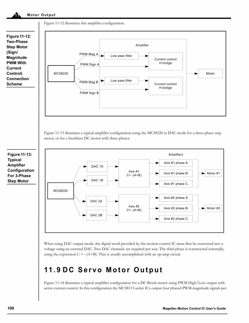
M o t o r O u t p u t11
Figure 11-12 illustrates this amplifier configuration.
Figure 11-13 illustrates a typical amplifier configuration using the MC58220 in DAC mode for a three-phase step motor, or for a brushless DC motor with three phases.
When using DAC output mode, the digital word provided by the motion control IC must first be converted into a voltage using an external DAC. Two DAC channels are required per axis. The third phase is constructed externally, using the expression C = –(A+B). This is usually accomplished with an op-amp circuit.
11 . 9 D C S e r v o M o t o r O u t p u t
Figure 11-14 illustrates a typical amplifier configuration for a DC Brush motor using PWM High/Low output with active current control. In this configuration the MC58113-series ICs output four phased PWM magnitude signals per
Figure 11-12: Two-Phase Step Motor (Sign/Magnitude PWM With Current Control) Connection Scheme
MC58220
Low pass filter
Low pass filter
Current control H-bridge
Current control H-bridge
Amplifier
PWM Mag A
PWM Sign A
PWM Mag B
PWM Sign B
Motor
MC58220
Axis #1 phase A
Axis #1 phase B
Axis #1 phase C
Axis #2 phase A
Axis #2 phase B
Axis #2 phase C
Motor #1
Motor #2
Amplifiers
DAC 1A
DAC 1B
DAC 2A
DAC 2B
Axis #1C= -(A+B)
Axis #2C= -(A+B)
Figure 11-13: Typical Amplifier Configuration For 3-Phase Step Motor
100 Magellan Motion Control IC User’s Guide

M o t o r O u t p u t 11
axis and use two leg current input signals to form a complete bridge controller with high performance current control. See the MC58113 Electrical Specification for more details on this motor drive configuration.
Figure 11-15 illustrates a typical amplifier configuration using DAC output mode.
Using the DAC output mode, the digital motor output word is typically converted into a DC signal with a value ranging between –10V to +10V. This signal can then be input into an off-the-shelf DC-Servo type amplifier or into any other analog input linear or switching amplifier.
If the motion control IC’s sign/magnitude PWM output mode is used there are two primary connection options. The first is to pass the PWM magnitude signal through a low pass filter, creating an analog reference signal that can be used with H-bridge amplifiers that provide current control. This is shown in Figure 11-16.
Alternatively the sign/magnitude outputs can directly drive an H-bridge in voltage mode (without active current control).
MC58113 or
MC51113 Current1A
Current1B GND
HV
AnalogConditioning
AnalogConditioning
MotorCoil
PWMLow1B
PWMHigh1B
PWMHigh1A
PWMLow1A
+ –
Pre-driver
Pre-driver
Figure 11-14: DC Brush Motor (PWM High/Low With Current Control) Connection Scheme (MC58113-Series ICs Only)
Figure 11-15: DC Brush Motor (DAC) Connection Scheme
MC58000
Motor #1
Motor #2
DAC 1A
DAC 2A
Analog InputAmplifier
Axis #1
Analog InputAmplifier
Axis #2
Magellan Motion Control IC User’s Guide 101

M o t o r O u t p u t11
11 . 1 0 P u l s e & D i r e c t i o n S i g n a l G e n e r a t i o n
(MC50000 only)
For step motors, in addition to signalling to drive each phase of a microstepping amplifier, step pulse and direction signals are provided to directly interface to amplifiers utilizing this format.
The step pulse signal, which is output by the motion control IC, consists of a precisely controlled series of individual pulses, each of which represents an increment of movement. This signal is always output as a square wave pulse train By default, a step pulse is considered to have occurred when the signal transitions from a low to a high output value. While not necessarily a 50% duty cycle, the square wave’s rising edges are precisely timed. To invert the interpretation of the pulse signal, use the SetSignalSense command. See Section 7.5.1, “Signal Sense Mask,” for more information.
The direction signal is synchronized with the pulse signal at the moment each pulse transition occurs. The direction signal is encoded so that a high value indicates a positive direction pulse, and a low value indicates a negative direction pulse. To invert this interpretation, use the SetSignalSense command. See Section 7.5.1, “Signal Sense Mask,” for more information. Note that if the direction signal is inverted, then if the position feedback mode is internal loop-back, the “A” encoder signal must be inverted also to preserve the correspondence between direction and actual motor motion.
Figure 11-16: DC Brush Motor (Sign/Magnitude PWM With Current Control) Connection Scheme
MC58000
Motor #1Low Pass Filter Current Control
H-Bridge
Axis #1
Current ControlH-Bridge
Axis #2
PWM Mag 1A
PWM Sign 1A
PWM Mag 2A
PWM Sign 2A
Low Pass FilterMotor #2
MC55220
Amplifier
Amplifier
Motor #1
Motor #2
Pulse
Pulse
Direction
Direction
Figure 11-17: Pulse and Direction Motor Output Connection Scheme
102 Magellan Motion Control IC User’s Guide

M o t o r O u t p u t 11
The Magellan series of motion control ICs support separate pulse rate modes using the command SetStepRange. The following table shows the values and resultant step ranges available using this command.
The ranges in the preceding example show the maximum and minimum ranges that can be generated by the motion control IC for the specified mode. For example, if the desired maximum step rate is 200 K steps per second, then the appropriate setting is SetStepRange 4.
For full-step and half-step applications, as well as pulse and direction applications that will have a maximum velocity of approximately 38 ksteps/sec, SetStepRange 8 should be used. For applications requiring higher pulse rates, one of the higher speed ranges should be specified.
A different step range can be programmed for each axis. To read the current step range setting, use the command GetStepRange.
See Chapter 14, “Step Motor Control,” for more information on step motor control.
C o m m a n d F r e q u e n c y r a n g e o f o u t p u t p u l s e s
SetStepRange 1 0 to 4.98 M steps per second.SetStepRange 4 0 to 622.5 K steps per second.SetStepRange 6 0 to 155.625 K steps per second.SetStepRange 8 0 to 38.90625 K steps per second.
The maximum pulse output rate on the MC55110 and MC58110 is 100K steps per second. The MC58113 maxi-mum rate is 1M steps per second. On these three devices the SetStepRange command cannot be used.
The pulse generator is designed so that a step occurs when the pulse transitions from low to high. Systems using step motor drivers which interpret a pulse as a high-to-low transition should use the SetSignalSense command to invert the signal sense. SetSignalSense can also be used to set the polarity of the Direction output. Refer to the Magellan Motion Control IC Programmer's Command Reference for information on SetSignalSense command.
Magellan Motion Control IC User’s Guide 103

M o t o r O u t p u t11
This page intentionally left blank.
104 Magellan Motion Control IC User’s Guide

12
1 2 . H o s t C o m m u n i c a t i o nIn This ChapterHost Communication Packets Parallel Communications Serial Port Controller Area Network (CAN) CommunicationsStoring Communication Values Using IONSPI (Serial Peripheral Interface) Communications
Magellan Motion Control ICs communicate with the host through one of four methods: a bi-directional parallel port, an asynchronous serial port, CANbus 2.0 standard, or SPI (Serial Peripheral Interface). However, not all Magellan processors support all communication modes. This is summarized in the table below.
* ION as well as various PMD card products also support Ethernet communications, although this functionality is implemented external to the Magellan IC.
1 2 . 1 H o s t C o m m u n i c a t i o n P a c k e ts
All communications to and from the Magellan, whether parallel, serial, CANbus, or SPI are in the form of packets. A packet is a sequence of transfers to and from the host, resulting in a Magellan action or data transfer. Packets may consist of a command with no data (dataless command), a command with associated data that are written to the chipset (write command), or a command with associated data that are read from the chipset (read command).
Every command sent by the host has a structured format that does not change, even if the amount of data and natureof the command vary. Each command has an instruction word (16 bits) that identifies the command. There may be zeroor more words of data associated with the command that the host writes to the motion control IC. This is followed byzero or more words of data that the host reads from the motion control IC. Finally, there is an optional checksum thatmay be read by the host to verify that communications are occurring properly. The type of command determineswhether there are data written to the motion control IC and to the host.
Most commands with associated data (read or write) have one, two, or three words of data. See the Magellan Motion ControlIC Programmer's Command Reference for more information on the length of specific commands. If a read or a writecommand has two words of associated data (a 32-bit quantity), the high word is loaded/read first, and the low word isloaded/read second.
Parallel Serial CANbus SPIMC50000 except MC58113 yes yes yes noMC58113 no yes yes yesION* no yes yes no
Magellan Motion Control IC User’s Guide 105

H o s t C o m mu n i c a t i o n12
The following tables show the generic command packet sequence for a dataless command, a write command, and aread command. The columns at the right of the tables list the corresponding hardware communication operation.
These are either a command write, a data read, or a data write.
Design Note: While some users will develop their own low-level libraries for interfacing to MC50000 motion control ICs and cards, PMD’s higher-level language tools, such as C-Motion and VB-Motion, provide convenient APIs (Application Programmmer Interface) for all Magellan commands.
D a ta l e s s C o m m a n d D a ta Tr a n s f e r
1 Command Write: Command Word2 (optional) Data Read: Packet Checksum
Wr i t e C o m m a n d D a ta Tr a n s f e r
1 Command Write: Command Word2 Data Write: Word 13 (optional) Data Write: Word 24 (optional) Data Write: Word 35 (optional) Data Read: Packet Checksum
R e a d C o m ma n d D a ta Tr a n s f e r
1 Command Write: Command Word2 (optional) Data Write: Word 13 Data Read: Word 14 (optional) Data Read: Word 25 (optional) Data Read: Packet Checksum
106 Magellan Motion Control IC User’s Guide

H o s t C o m mu n i c a t i o n 12
1 2 . 2 P a r a l l e l C o m m u n i c a t i o n s
(MC50000 except MC58113)
MC58000 products except MC58113 offer a parallel word interface for connection to microprocessors or I/O ports that use this fornat. Figure 12-1 provides an overview of this connection scheme.
The parallel port is configured to operate in one of two modes, 16-bit and 8-bit, as described in the following table. Although 16-bit communication is faster and simpler to implement, 8-bit communication may be useful for direct interface with microprocessors that have an 8-bit external interface.
The parallel port configuration is determined by HostMode1 and HostMode0 pins on the MC5000’s I/O chip. For more information see the Magellan Motion Control IC Electrical Specifications.
1 2 . 2 . 1 I n t e r f a c i n g
Five control signals synchronize communications through the parallel port: ~HostSlct, HostRdy, ~HostWrite, ~HostRead, and HostCmd. The descriptions of these signals are as follows.
16-bit mode The motion control IC transfers instructions and data as full 16-bit words, using the entire 16-bit data path.
8-bit mode The motion control IC transfers instructions and data as full 16-bit words, using an 8-bit data path. Words are transferred in two successive bytes; the high-order byte of each word is transferred first in all cases. This mode allows access to all features of the Magellan instruction set, even when the host is limited to an 8-bit data path.
S i g n a l D e s c r i p t i o n
~HostSlct Set by host—when this signal is asserted (low), the host parallel port is selected for opera-tions.
Figure 12-1: Parallel Communication Interconnec-tions
Host
Magellan Motion Processor
Ho
stD
ata0
- 1
5
~H
ostS
lct
Hos
tRdy
~H
ostW
rite
~H
ostR
ead
Hos
tCm
d
Hos
tInt
pt
CAN 2.0B network
Serial network
System clock
(40 MHz)
Pa
ralle
l por
t
Magellan Motion Control IC User’s Guide 107

H o s t C o m mu n i c a t i o n12
1 2 . 2 . 2 P a r a l l e l P o r t I / O O p e r a t i o n s
Using the five parallel port control signals of ~HostSlct, HostRdy, ~HostWrite, ~HostRead, and HostCmd, it is possible to perform all necessary operations to send commands to the motion control IC.
The three operations are: the instruction word write, the data word write, and the data word read. By performing these operations in the correct sequence, the complete command packets can be assembled and sent to the motion control IC. Command format is discussed in the Magellan Motion Control IC Programmer’s Command Reference.
instruction word write — In 16-bit bus mode, this is accomplished by asserting ~HostSlct and ~HostWrite low,asserting HostCmd high, and loading the data bus with the desired 16-bit instruction word value. In 8-bitbus mode, the control signals are the same, except that only the low 8 bits of the data bus hold data, and theoperation is performed twice. On the first 8-bit write, the data bus should contain the high byte of theinstruction word. On the second 8-bit write, the data should contain the low byte of the instruction word.
data word write —In 16-bit bus mode this is accomplished by asserting ~HostSlct, and ~HostWrite low,asserting HostCmd low, and loading the data bus with the desired 16-bit data word value. In 8-bit bus mode,the control signals are the same, except that only the low 8 bits of the data bus hold data, and the operationis performed twice. On the first 8-bit write, the data bus should contain the high byte of the data word. Onthe second 8-bit write, the data should contain the low byte of the data word.
data word read—In 16-bit bus mode this is accomplished by asserting ~HostSlct, and ~HostRead low,asserting HostCmd low, and storing the value asserted by the motion control IC on the 16-bit data bus. Onthe first 8-bit read, the data bus will contain the high byte of the data word. On the second 8-bit read, thedata will contain the low byte of the data word.
At the beginning of each of these operations, the HostRdy signal must be high. This indicates that the motion control IC is ready to receive or transmit a new data or instruction word. In between 8-bit transfers, the HostRdy does not need to be checked. For example, after checking the HostRdy for the high byte of any of these 2-byte transfers (instruction word write, data word write, or data word read), the HostRdy does not have to be checked again to transfer the low byte.
HostRdy Set by motion control IC—when high, indicates to the host that the motion control IC's host port is available for operations.
~HostWrite Set by host—when asserted low, allows a data transfer from the host to the motion control IC.
~HostRead Set by host—when asserted low, allows a data word to be read by the host from the motion control IC.
HostCmd Used in conjunction with the ~HostRead and ~HostWrite signals as follows:When and HostCmd is Then~HostWrite is low low write data word to motion control IC
high write instruction word to motion control IC.
~HostRead is low low read data word from motion control IC.
high read status word from motion control IC (see Section 12.2.3, “The St a t u s R e a d Opera-tion” for more information).
S i g n a l D e s c r i p t i o n
108 Magellan Motion Control IC User’s Guide

H o s t C o m mu n i c a t i o n 12
For more detailed electrical information on these operations, see the pin descriptions and timing diagrams in the Magellan Motion Control IC Electrical Specifications document for your motion control IC model.
1 2 . 2 . 3 T h e S ta t u s R e a d O p e r a t i o n
There is a special operation called a status read, which is not directly related to reading or writing to the motion control IC. The status read allows the user to determine the state of some of the motion control IC’s host interface signals and flags without having to develop special decode logic.
A status read operation is performed by asserting ~HostRead and ~HostSlct low, HostCmd high, and reading the data bus. The resultant data word sent by the motion control IC contains the following information:.
1 2 . 2 . 4 C h e c k s u m
It is possible to retrieve a checksum at the end of each read and/or write command. The checksum may enhance reliability for critical applications, particularly in very noisy electrical environments. Checksums may also be helpful in situations where the communication signals are routed over a medium that may have data losses. The checksum consists of the low-order 16 bits of the sum of all preceding words transmitted in the command. For example, if a SetVelocity instruction (which takes two 16-bit words of data) is sent with a data value of FEDCBA98 (hex), the checksum would be:
0011h code for SetVelocity instruction+ FEDCh first data word+ BA98h second data word= 1B985h checksum = B985 (low-order 16 bits only)
Reading the checksum is optional. Recovery from an incorrect command transfer (bad checksum) will depend on the nature of the packet. Buffered operations can always be re-transmitted, but a non-buffered instruction (one that causes an immediate action) might or might not be re-transmitted, depending on the instruction and the state of the axis.
Before any parallel host I/O operation is performed, the user must make sure that the HostRdy signal is high (motion control IC ready). After each word (instruction or data) is read or written, this signal will go low (motion control IC busy). It will return to ready when the motion control IC is ready to transfer the next word.
B i t n u m b e r D e s c r i p t i o n
0–12 Not used.13 Indicates whether an instruction error has occurred (see Section 12.2.5, “Instruction Errors” for
more information).14 Holds value of HostIntrpt signal. A value of one indicates the signal level is high.
15 Holds value of HostRdy signal. A value of one indicates the signal level is high.
Status reads may be performed at any time regardless of the state of the HostRdy signal.
Magellan Motion Control IC User’s Guide 109
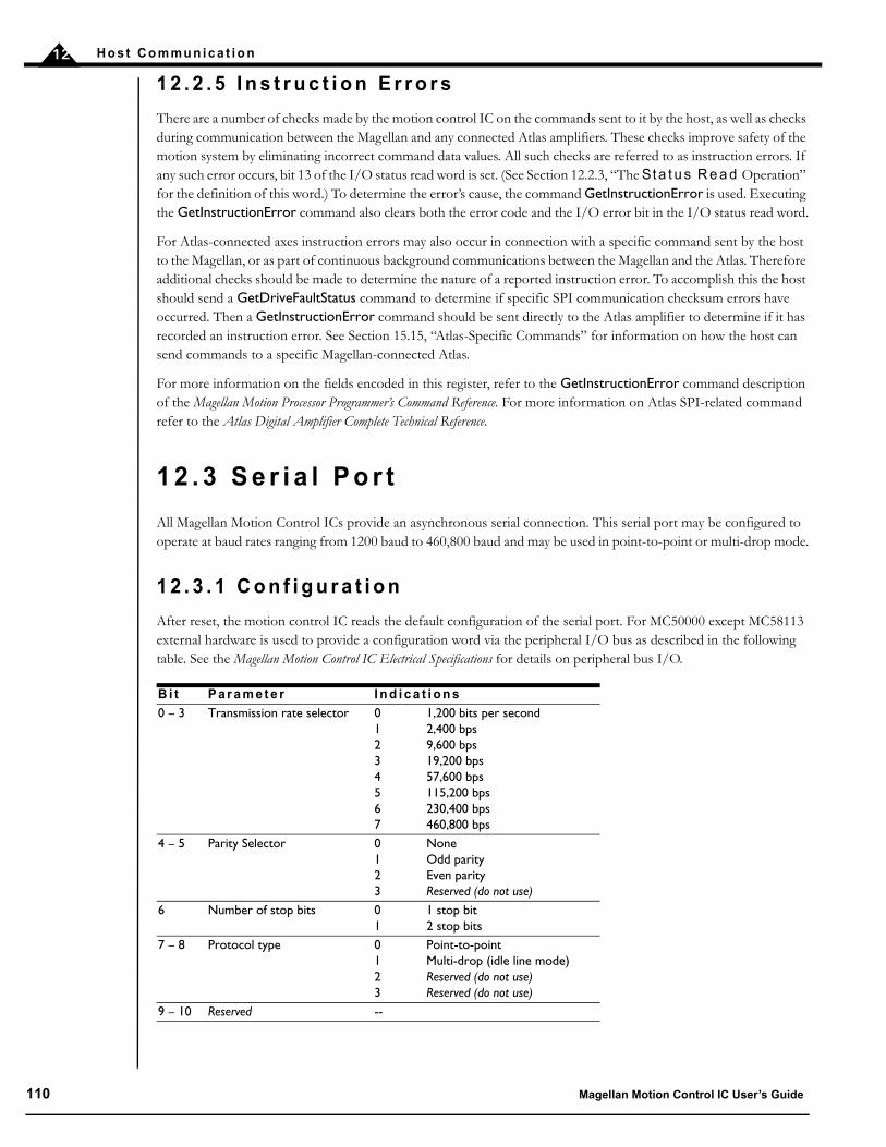
H o s t C o m mu n i c a t i o n12
1 2 . 2 . 5 I n s t r u c t i o n E r r o r s
There are a number of checks made by the motion control IC on the commands sent to it by the host, as well as checks during communication between the Magellan and any connected Atlas amplifiers. These checks improve safety of the motion system by eliminating incorrect command data values. All such checks are referred to as instruction errors. If any such error occurs, bit 13 of the I/O status read word is set. (See Section 12.2.3, “The St a t u s R e a d Operation” for the definition of this word.) To determine the error’s cause, the command GetInstructionError is used. Executing the GetInstructionError command also clears both the error code and the I/O error bit in the I/O status read word.
For Atlas-connected axes instruction errors may also occur in connection with a specific command sent by the host to the Magellan, or as part of continuous background communications between the Magellan and the Atlas. Therefore additional checks should be made to determine the nature of a reported instruction error. To accomplish this the host should send a GetDriveFaultStatus command to determine if specific SPI communication checksum errors have occurred. Then a GetInstructionError command should be sent directly to the Atlas amplifier to determine if it has recorded an instruction error. See Section 15.15, “Atlas-Specific Commands” for information on how the host can send commands to a specific Magellan-connected Atlas.
For more information on the fields encoded in this register, refer to the GetInstructionError command description of the Magellan Motion Processor Programmer’s Command Reference. For more information on Atlas SPI-related command refer to the Atlas Digital Amplifier Complete Technical Reference.
1 2 . 3 S e r i a l P o r t
All Magellan Motion Control ICs provide an asynchronous serial connection. This serial port may be configured to operate at baud rates ranging from 1200 baud to 460,800 baud and may be used in point-to-point or multi-drop mode.
1 2 . 3 . 1 C o n f i g u r a t i o n
After reset, the motion control IC reads the default configuration of the serial port. For MC50000 except MC58113 external hardware is used to provide a configuration word via the peripheral I/O bus as described in the following table. See the Magellan Motion Control IC Electrical Specifications for details on peripheral bus I/O.
B i t P a r a m e t e r I n d i c a t i o n s
0 – 3 Transmission rate selector 0 1,200 bits per second1 2,400 bps2 9,600 bps3 19,200 bps4 57,600 bps5 115,200 bps6 230,400 bps7 460,800 bps
4 – 5 Parity Selector 0 None1 Odd parity2 Even parity3 Reserved (do not use)
6 Number of stop bits 0 1 stop bit1 2 stop bits
7 – 8 Protocol type 0 Point-to-point1 Multi-drop (idle line mode)2 Reserved (do not use)3 Reserved (do not use)
9 – 10 Reserved --
110 Magellan Motion Control IC User’s Guide
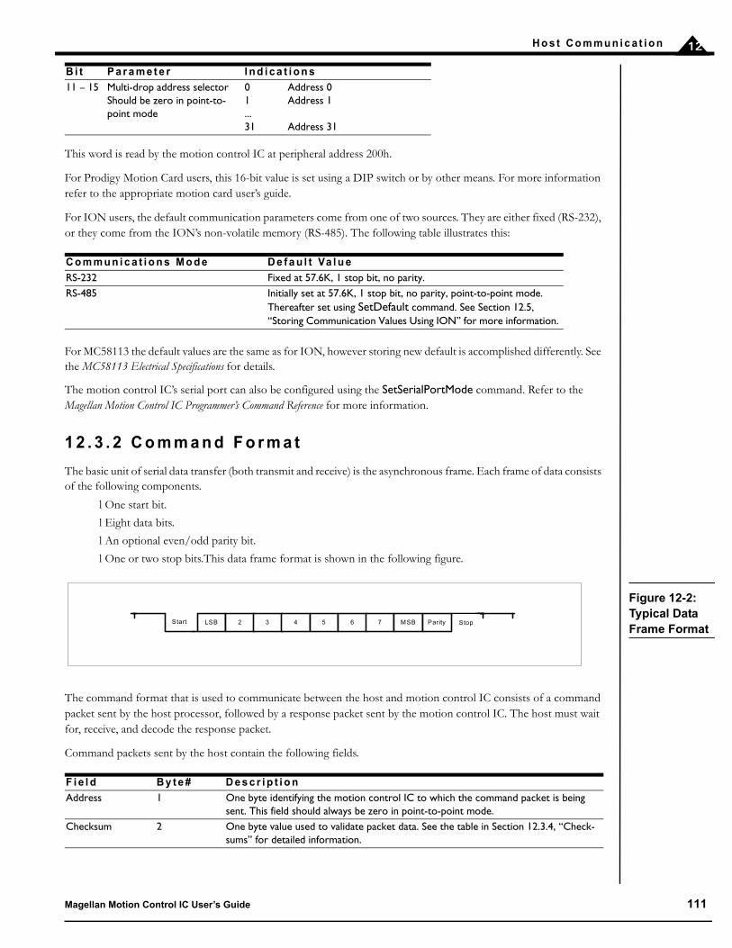
H o s t C o m mu n i c a t i o n 12
This word is read by the motion control IC at peripheral address 200h.
For Prodigy Motion Card users, this 16-bit value is set using a DIP switch or by other means. For more information refer to the appropriate motion card user’s guide.
For ION users, the default communication parameters come from one of two sources. They are either fixed (RS-232), or they come from the ION’s non-volatile memory (RS-485). The following table illustrates this:
For MC58113 the default values are the same as for ION, however storing new default is accomplished differently. See the MC58113 Electrical Specifications for details.
The motion control IC’s serial port can also be configured using the SetSerialPortMode command. Refer to the Magellan Motion Control IC Programmer’s Command Reference for more information.
1 2 . 3 . 2 C o m m a n d F o r m a t
The basic unit of serial data transfer (both transmit and receive) is the asynchronous frame. Each frame of data consists of the following components.
l One start bit.
l Eight data bits.
l An optional even/odd parity bit.
l One or two stop bits.This data frame format is shown in the following figure.
The command format that is used to communicate between the host and motion control IC consists of a command packet sent by the host processor, followed by a response packet sent by the motion control IC. The host must wait for, receive, and decode the response packet.
Command packets sent by the host contain the following fields.
11 – 15 Multi-drop address selectorShould be zero in point-to-point mode
0 Address 01 Address 1...31 Address 31
C o m m u n i c a t i o n s M o d e D e f a u l t Va l u e
RS-232 Fixed at 57.6K, 1 stop bit, no parity.RS-485 Initially set at 57.6K, 1 stop bit, no parity, point-to-point mode.
Thereafter set using SetDefault command. See Section 12.5, “Storing Communication Values Using ION” for more information.
F i e l d B y t e # D e s c r i p t i o n
Address 1 One byte identifying the motion control IC to which the command packet is being sent. This field should always be zero in point-to-point mode.
Checksum 2 One byte value used to validate packet data. See the table in Section 12.3.4, “Check-sums” for detailed information.
B i t P a r a m e t e r I n d i c a t i o n s
Figure 12-2: Typical Data Frame Format
LSB 2 3 4 5 6 7 MSB Parity StopStart
Magellan Motion Control IC User’s Guide 111
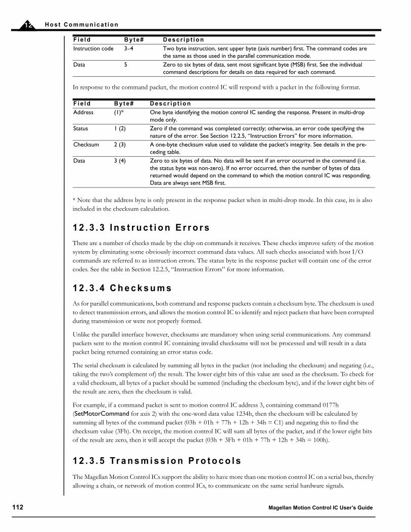
H o s t C o m mu n i c a t i o n12
In response to the command packet, the motion control IC will respond with a packet in the following format.
* Note that the address byte is only present in the response packet when in multi-drop mode. In this case, its is also included in the checksum calculation.
1 2 . 3 . 3 I n s t r u c t i o n E r r o r s
There are a number of checks made by the chip on commands it receives. These checks improve safety of the motion system by eliminating some obviously incorrect command data values. All such checks associated with host I/O commands are referred to as instruction errors. The status byte in the response packet will contain one of the error codes. See the table in Section 12.2.5, “Instruction Errors” for more information.
1 2 . 3 . 4 C h e c k s u m s
As for parallel communications, both command and response packets contain a checksum byte. The checksum is used to detect transmission errors, and allows the motion control IC to identify and reject packets that have been corrupted during transmission or were not properly formed.
Unlike the parallel interface however, checksums are mandatory when using serial communications. Any command packets sent to the motion control IC containing invalid checksums will not be processed and will result in a data packet being returned containing an error status code.
The serial checksum is calculated by summing all bytes in the packet (not including the checksum) and negating (i.e., taking the two’s complement of) the result. The lower eight bits of this value are used as the checksum. To check for a valid checksum, all bytes of a packet should be summed (including the checksum byte), and if the lower eight bits of the result are zero, then the checksum is valid.
For example, if a command packet is sent to motion control IC address 3, containing command 0177h (SetMotorCommand for axis 2) with the one-word data value 1234h, then the checksum will be calculated by summing all bytes of the command packet (03h + 01h + 77h + 12h + 34h = C1) and negating this to find the checksum value (3Fh). On receipt, the motion control IC will sum all bytes of the packet, and if the lower eight bits of the result are zero, then it will accept the packet (03h + 3Fh + 01h + 77h + 12h + 34h = 100h).
1 2 . 3 . 5 Tr a n s m i s s i o n P r o t o c o l s
The Magellan Motion Control ICs support the ability to have more than one motion control IC on a serial bus, thereby allowing a chain, or network of motion control ICs, to communicate on the same serial hardware signals.
Instruction code 3–4 Two byte instruction, sent upper byte (axis number) first. The command codes are the same as those used in the parallel communication mode.
Data 5 Zero to six bytes of data, sent most significant byte (MSB) first. See the individual command descriptions for details on data required for each command.
F i e l d B y t e # D e s c r i p t i o n
Address (1)* One byte identifying the motion control IC sending the response. Present in multi-drop mode only.
Status 1 (2) Zero if the command was completed correctly; otherwise, an error code specifying the nature of the error. See Section 12.2.5, “Instruction Errors” for more information.
Checksum 2 (3) A one-byte checksum value used to validate the packet's integrity. See details in the pre-ceding table.
Data 3 (4) Zero to six bytes of data. No data will be sent if an error occurred in the command (i.e. the status byte was non-zero). If no error occurred, then the number of bytes of data returned would depend on the command to which the motion control IC was responding. Data are always sent MSB first.
F i e l d B y t e # D e s c r i p t i o n
112 Magellan Motion Control IC User’s Guide

H o s t C o m mu n i c a t i o n 12
There are two methods supported by the serial port to resolve timing problems, transmission conflicts, and other issues that may occur during serial operations. These are point-to-point (used when there is only one device connected to the serial port) and multi-drop idle-line mode (used when there are multiple devices on the serial bus). The following sections describe these transmission protocols.
1 2 . 3 . 6 P o i n t - t o - P o i n t M o d e
Point-to-point serial mode is intended to be used when there is a direct serial connection between one host and one motion control IC. In this mode, the address byte in the command packet is not used by the motion control IC (except in the calculation of the checksum), and the motion control IC responds to all commands sent by the host.
When in point-to-point mode, there are no timing requirements on the data transmitted within a packet. The amount of data contained in a command packet is determined by the command code in the packet. Each command code has a specific amount of data associated with it. When the motion control IC receives a command code, it waits for all data bytes to be received before processing the command. The amount of data returned from any command is also determined by the command code. After processing a command, the motion control IC will respond with a data packet of the necessary length. No address byte is sent with this response packet.
When running in point-to-point mode, there is no direct way for the motion control IC to determine the beginning of a new command packet, except by context. Therefore, it is important for the host to remain synchronized with the motion control IC when sending and receiving data. To ensure that the processors remain synchronized, it is recommended that the host processor implement a time limit when waiting for data packets to be sent by the motion control IC. The suggested minimum timeout period is the amount of time required to send one byte at the selected baud rate plus one millisecond. For example, at 9600 baud each bit takes 1/9600 seconds to transfer, and a typical byte consists of 8 data bits, 1 start bit, and 1 stop bit. Therefore, one byte takes just over 1 millisecond, and the recommended minimum timeout is 2 milliseconds.
If the timeout period elapses between bytes of received data while the host is waiting on a data packet, then the host should assume that it is out of synchronization with the motion control IC. To resynchronize, the host should send a byte containing zero data and wait for a data packet to be received. This process should be repeated until a data packet is received from the motion control IC; at which point the two processors will be synchronized.
1 2 . 3 . 7 M u l t i - d r o p I d l e - l i n e M o d e
This multi-drop protocol is intended to be used on a serial bus in which a single host processor communicates with multiple motion control ICs (or other subordinate devices). In this mode, the address byte that starts a command packet is used to indicate the device for which the packet is intended. Only the addressed device will respond to the packet. Therefore, it is important to properly set up the motion control IC address (using the serial configuration word previously described) and to include this address as the first byte of any command packet destined for the motion control IC.
When the idle-line mode is used, the motion control IC imposes tight timing requirements on the data sent as part of a command packet. In this mode, the motion control IC will interpret the first byte received after an idle period as the start of a new packet. Any data already received will be discarded.
The timeout period is equal to the time required to send ten bits of serial data at the configured baud rate—for example, roughly 1 millisecond at 9600 baud. If a delay of this length occurs between bytes of a command packet, then the bytes already received will be discarded, and the first character received after the delay will be interpreted as the address byte of a new packet.
Once the motion control IC receives an address byte and a command code, it waits for all data bytes to be received before processing the command. The amount of data returned from any command is also determined by the command code. After processing a command, the motion control IC will respond with a data packet of the necessary
Magellan Motion Control IC User’s Guide 113

H o s t C o m mu n i c a t i o n12
length. In multi-drop mode, the first byte of every response packet contains the address of the responding motion control IC. This prevents other devices on the network from interpreting the response as a command sent to them.
Note that this multi-drop protocol may also be used when the host and motion control IC are wired in a point-to-point configuration, as long as the host always transmits the correct address byte at the start of a packet and follows any additional rules for the selected protocol. This mode of operation allows the host to ensure that it will remain synchronized with the motion control IC without implementing the timeout and re-synch procedure previously outlined.
1 2 . 4 C o n t r o l l e r A r e a N e t w o r k ( C A N ) C o m m u n i c a t i o n s
1 2 . 4 . 1 O v e r v i e w
CAN is a serial bus system especially suited for networking “intelligent” devices as well as sensors and actuators within a system or sub-system.
All Magellan Motion Control ICs provide a CAN 2.0B network and will coexist (but not communicate) with CANOpen nodes on that network. Magellan uses CAN to receive commands, send responses, and (optionally) send asynchronous event notifications. Each message type has an address, as shown in the following table.
CAN nodes communicate via messages. Each message may carry a data payload of up to 8 bytes. The CAN interface layer automatically corrects transmission errors. Unlike the serial and parallel protocols, a checksum is not a part of the motion control IC’s CAN interface protocol.
1 2 . 4 . 2 M e s s a g e F o r m a t
Messages are transmitted and received using the standard format identifier length of 11 bits. All network messages that use the extended format 29-bit identifier are ignored by the motion control IC. The data formats for the three message types listed in the previous table are expressed in terms of the byte sequences for the parallel interface. Commands have varying data lengths; see the Magellan Motion Control IC Programmer’s Command Reference for the data formats of particular commands. In the following table, bytes that will always be present independent of the command being processed are marked as Required.
The corresponding byte sequences in the CAN protocol for the three message types are described in the following tables.
M e s s a g e Ty p e C A N A d d r e s s
Command received 0x600 + nodeIDCommand response 0x580 + nodeIDEvent notification 0x180 + nodeID
C o m m a n d R e c e i v e d
M e s s a g e d a ta b y t e R e q u i r e d ?
C o r r e s p o n d i n g pa r a l l e l b y t e
1 Y Command word, high byte2 Y Command word, low byte3 N 1st data word, high byte4 N 1st data word, low byte5 N 2nd data word, high byte
114 Magellan Motion Control IC User’s Guide

H o s t C o m mu n i c a t i o n 12
The first word in a response will contain a value of zero in the upper byte, and the lower byte will contain a value that will also be zero in a no-error condition, but will be non-zero if an error occurred while processing the instruction. (See Section 12.2.5, “Instruction Errors” for more information.) The byte following the status byte will be the high byte of the 1st data word, followed by the low byte of the 1st data word and continuing as shown in the preceding table. The actual number of bytes returned is determined by the instruction that was issued; see the Magellan Motion Control IC Programmer’s Command Reference for the data lengths and formats of each command.
The first byte in a notification message will contain a value of zero with the second byte indicating the axis from which the notification was sent. The 3rd and 4th bytes are the high and low byte of the Event Status register from the notifying axis.
1 2 . 4 . 3 C o n f i g u r i n g t h e C A N I n t e r f a c e
After reset, MC58000 motion control ICs except MC58113 read a 16-bit value from their peripheral bus (location 400h), to set the default configuration of the CAN interface. Refer to the Magellan Motion Control IC Electrical Specifications for details on peripheral bus I/O.
ION can permanently store interface parameters using the SetDefault command. See Section 12.5, “Storing Communication Values Using ION” for more information. MC58113 also allows permanent storage of
6 N 2nd data word, low byte7 N 3rd data word, high byte8 N 3rd data word, low byte
C o m m a n d R e s p o n s e
M e s s a g e d a ta b y t e R e q u i r e d ?
C o r r e s p o n d i n g pa r a l l e l b y t e
1 Y Reserved (always zero)2 Y Instruction status code3 N 1st data word, high byte4 N 1st data word, low byte5 N 2nd data word, high byte6 N 2nd data word, low byte7 N 3rd data word, high byte8 N 3rd data word, low byte
E v e n t N o t i f i c a t i o n
M e s s a g e d a ta b y t e D a ta I n t e r p r e ta t i o n
1 reserved (always zero)2 axis number (0–3)3 Event Status register value, high byte4 Event Status register value, low byte
C o m m a n d R e c e i v e d
M e s s a g e d a ta b y t e R e q u i r e d ?
C o r r e s p o n d i n g pa r a l l e l b y t e
Magellan Motion Control IC User’s Guide 115
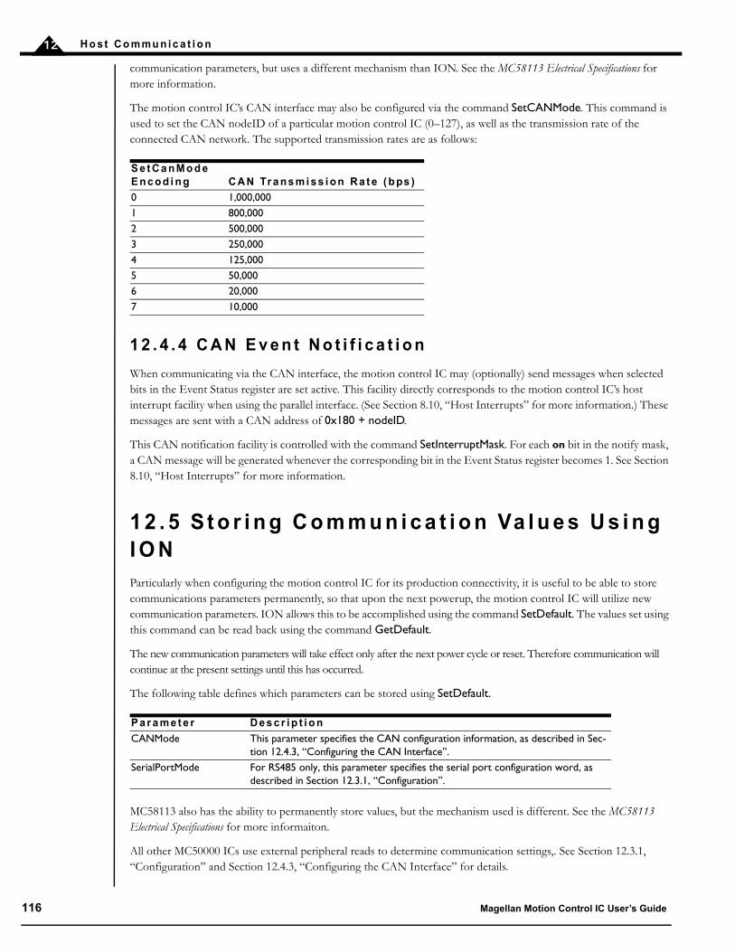
H o s t C o m mu n i c a t i o n12
communication parameters, but uses a different mechanism than ION. See the MC58113 Electrical Specifications for more information.
The motion control IC’s CAN interface may also be configured via the command SetCANMode. This command is used to set the CAN nodeID of a particular motion control IC (0–127), as well as the transmission rate of the connected CAN network. The supported transmission rates are as follows:
1 2 . 4 . 4 C A N E v e n t N o t i f i c a t i o n
When communicating via the CAN interface, the motion control IC may (optionally) send messages when selected bits in the Event Status register are set active. This facility directly corresponds to the motion control IC’s host interrupt facility when using the parallel interface. (See Section 8.10, “Host Interrupts” for more information.) These messages are sent with a CAN address of 0x180 + nodeID.
This CAN notification facility is controlled with the command SetInterruptMask. For each on bit in the notify mask, a CAN message will be generated whenever the corresponding bit in the Event Status register becomes 1. See Section 8.10, “Host Interrupts” for more information.
1 2 . 5 S t o r i n g C o m m u n i c a t i o n Va l u e s U s i n g I O NParticularly when configuring the motion control IC for its production connectivity, it is useful to be able to store communications parameters permanently, so that upon the next powerup, the motion control IC will utilize new communication parameters. ION allows this to be accomplished using the command SetDefault. The values set using this command can be read back using the command GetDefault.
The new communication parameters will take effect only after the next power cycle or reset. Therefore communication will continue at the present settings until this has occurred.
The following table defines which parameters can be stored using SetDefault.
MC58113 also has the ability to permanently store values, but the mechanism used is different. See the MC58113 Electrical Specifications for more informaiton.
All other MC50000 ICs use external peripheral reads to determine communication settings,. See Section 12.3.1, “Configuration” and Section 12.4.3, “Configuring the CAN Interface” for details.
S e t C a n M o d e E n c o d i n g C A N Tr a n s m i s s i o n R a t e ( b ps )
0 1,000,000 1 800,000 2 500,000 3 250,0004 125,000 5 50,0006 20,0007 10,000
P a r a m e t e r D e s c r i p t i o n
CANMode This parameter specifies the CAN configuration information, as described in Sec-tion 12.4.3, “Configuring the CAN Interface”.
SerialPortMode For RS485 only, this parameter specifies the serial port configuration word, as described in Section 12.3.1, “Configuration”.
116 Magellan Motion Control IC User’s Guide
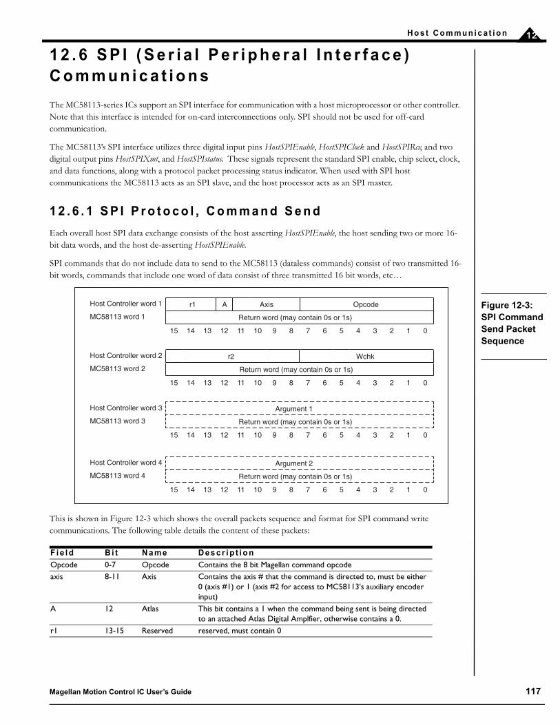
H o s t C o m mu n i c a t i o n 12
1 2 . 6 S P I ( S e r i a l P e r i p h e r a l I n t e r f a c e ) C o m m u n i c a t i o n s
The MC58113-series ICs support an SPI interface for communication with a host microprocessor or other controller. Note that this interface is intended for on-card interconnections only. SPI should not be used for off-card communication.
The MC58113’s SPI interface utilizes three digital input pins HostSPIEnable, HostSPIClock and HostSPIRcv, and two digital output pins HostSPIXmt, and HostSPIstatus. These signals represent the standard SPI enable, chip select, clock, and data functions, along with a protocol packet processing status indicator. When used with SPI host communications the MC58113 acts as an SPI slave, and the host processor acts as an SPI master.
1 2 . 6 . 1 S P I P r o t o c o l , C o m m a n d S e n d
Each overall host SPI data exchange consists of the host asserting HostSPIEnable, the host sending two or more 16-bit data words, and the host de-asserting HostSPIEnable.
SPI commands that do not include data to send to the MC58113 (dataless commands) consist of two transmitted 16-bit words, commands that include one word of data consist of three transmitted 16 bit words, etc…
This is shown in Figure 12-3 which shows the overall packets sequence and format for SPI command write communications. The following table details the content of these packets:
F i e l d B i t N a m e D e s c r i p t i o n
Opcode 0-7 Opcode Contains the 8 bit Magellan command opcodeaxis 8-11 Axis Contains the axis # that the command is directed to, must be either
0 (axis #1) or 1 (axis #2 for access to MC58113's auxiliary encoder input)
A 12 Atlas This bit contains a 1 when the command being sent is being directed to an attached Atlas Digital Amplfier, otherwise contains a 0.
r1 13-15 Reserved reserved, must contain 0
Figure 12-3: SPI Command Send Packet Sequence
Host Controller word 1 r1 A Axis Opcode
MC58113 word 1 Return word (may contain 0s or 1s)
15 14 13 12 11 10 9 8 7 6 5 4 3 2 1 0
Host Controller word 2 r2 Wchk
MC58113 word 2 Return word (may contain 0s or 1s)
15 14 13 12 11 10 9 8 7 6 5 4 3 2 1 0
Host Controller word 3 Argument 1
MC58113 word 3 Return word (may contain 0s or 1s)
15 14 13 12 11 10 9 8 7 6 5 4 3 2 1 0
Host Controller word 4 Argument 2
MC58113 word 4 Return word (may contain 0s or 1s)
15 14 13 12 11 10 9 8 7 6 5 4 3 2 1 0
Magellan Motion Control IC User’s Guide 117
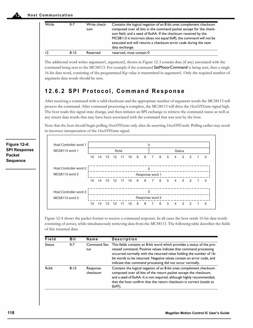
H o s t C o m mu n i c a t i o n12
The additional word writes argument1, argument2, shown in Figure 12-3 contain data (if any) associated with the command being sent to the MC58113. For example if the command SetMotorCommand is being sent, then a single 16-bit data word, consisting of the programmed Kp value is transmitted in argument1. Only the required number of argument data words should be sent.
1 2 . 6 . 2 S P I P r o t o c o l , C o m m a n d R e s p o n s e
After receiving a command with a valid checksum and the appropriate number of argument words the MC58113 will process the command. After command processing is complete, the MC58113 will drive the HostSPIStatus signal high. The host reads this signal state change, and then initiates an SPI exchange to retrieve the command status as well as any return data words that may have been associated with the command that was sent by the host.
Note that the host should begin polling HostSPIStatus only after de-asserting HostSPIEnable. Polling earlier may result in incorrect interpretation of the HostSPIStatus signal.
Figure 12-4 shows the packet format to receive a command response. In all cases the host sends 16-bit data words consisting of zeroes, while simultaneously retrieving data from the MC58113. The following table describes the fields of this returned data:
Wchk 0-7 Write check-sum
Contains the logical negation of an 8-bit ones complement checksum computed over all bits in the command packet except for the check-sum field, and a seed of 0xAA. If the checksum received by the MC58113 is incorrect (does not equal 0xff), the command will not be executed and will returns a checksum error code during the next data exchange.
r2 8-15 Reserved reserved, must contain 0
F i e l d B i t N a m e D e s c r i p t i o n
Status 0-7 Command Sta-tus
This fields contains an 8-bit word which provides a status of the pro-cessed command. Positive values indicate that command processing occurred normally with the returned value holding the number of 16-bit words to be returned. Negative values contain an error code, and indicate that command processing did not occur normally.
Rchk 8-15 Response checksum
Contains the logical negation of an 8-bit ones complement checksum computed over all bits of the return packet except the checksum, and a seed of 0xAA. It is not required, although highly recommended, that the host confirm that the return checksum is correct (totals to 0xFF).
Figure 12-4: SPI Response Packet Sequence
0
Rchk Status
15 14 13 12 11 10 9 8 7 6 5 4 3 2 1 0
0
Response word 1
15 14 13 12 11 10 9 8 7 6 5 4 3 2 1 0
0
Response word 2
15 14 13 12 11 10 9 8 7 6 5 4 3 2 1 0
Host Controller word 1
MC58113 word 1
Host Controller word 2
MC58113 word 2
Host Controller word 3
MC58113 word 3
118 Magellan Motion Control IC User’s Guide

H o s t C o m mu n i c a t i o n 12
The additional word reads response1, response2, shown in Figure 12-4 contain data (if any) associated with the command that was sent to the MC58113. For example if the command GetMotorCommand was sent, then a single 16-bit data word, consisting of the current value of the MC58113’s motor command register, will be returned.
1 2 . 6 . 3 C o n f i g u r i n g H o s t S P I
There are no user-configurable parameters that need to be set for the Host SPI interface. For more information on HOSTSPI interface timing and signalling refer to the MC58113 Electrical Specifications.
If the host attempts to retrieve command status before it is ready an error will occur. The signal HostSPIStatus should always be used to synchronize command status checks.
Even if no data is being returned by the MC58113, the host must retrieve the command response. Failure to do so will result in SPI communciations becoming desynchronized.
Magellan Motion Control IC User’s Guide 119

H o s t C o m mu n i c a t i o n12
This page intentionally left blank.
120 Magellan Motion Control IC User’s Guide
13
1 3 . B r u s h l e s s D C M o t o r C o n t r o lIn This ChapterOverview Number of Phases Phasing Control Modes Phase Counts Phase Initialization Phase Initialization Programming Automatic Phase CorrectionEncoder Prescaler Sinusoidal Commutation Field Oriented Control
1 3 . 1 O v e r v i e w
Magellan Motion Control ICs provide a number of special features for support of brushless motors. These include input of Hall sensors, support for sinusoidal commutation, and support for 2- or 3-phase motors. Magellan ICs that provide current control or Atlas-connected Magellan axes also provide additional features including field oriented control (FOC).
There are several approaches used to generate the correct phasing and motor excitation signal to drive brushless DC motors. The first uses Hall sensors to generate the desired output waveforms. The second uses the encoder, and utilizes sinusoidal or field oriented control to drive the phases. A “third” option for driving a brushless DC motor is using an amplifier that provides its own commutation. This effectively converts the controller into a single-phase DC brush motor type.
The following table shows the control modes available for various Magellan ICs.
Broadly speaking, the control tasks that are specific to multi-phase motors can be broken down into an initialization phase, when the exact correct phase angle may not yet be known, and motor operation, when phase initialization is complete and the motor is rotating and operating normally. For both of these modes, before correct phasing can occur, a number of parameters must be setup correctly. The following sections describe these parameters.
M a g e l l a n P r o d u c t C o n t r o l M o d e s Av a i l a b l e C u r r e n t C o n t r o l Av a i l a b l e
MC58000 Hall-based commutationSinusoidal commutation
No
ION, MC58113, or Atlas-connected Magellan axes
Hall-based commutationSinusoidal commutationField oriented control
Yes
Magellan Motion Control IC User’s Guide 121

B r u s h l e s s D C Mo t o r C o n t r o l13
1 3 . 2 N u m b e r o f P h a s e s
The MC58000 supports two commutation waveforms: a 120-degree offset waveform appropriate for 3-phase brushless motors, and a 90-degree offset waveform appropriate for 2-phase brushless motors.
To specify the waveform, the command SetMotorType is used. This command is not required for ION, which defaults to the specific motor and waveform type that it supports.
Figure 13-1 illustrates the phase A, B, and C commutation signals for a 3-phase brushless motor, and the phase A and phase B signals for a 2-phase brushless motor.
1 3 . 3 P h a s i n g C o n t r o l M o d e s
To drive a brushless DC motor correctly, the motor’s rotor angle must be known as it continually changes. This is accomplished using one of two methods. The first is by using Hall sensors, and the second is by using a position encoder. In both cases these sensors must be directly connected to the motor shaft. Generally speaking, if an encoder is available it should be used, as it will provide smoother motion and higher overall performance than Hall sensors.
To select whether the phasing of the motor will be Hall-based or encoder-based, the command SetCommutationMode is used. The value set can be read back using the command GetCommutationMode.
For ION or Atlas-connected axes, if field oriented control is desired, then the command SetCurrentControlMode is used with a value of FOC. The value set may be read back using the command GetCurrentControlMode. Selection of field oriented control does not affect selection of Hall-based or encoder-based phasing, although if an encoder is available, it is recommended that it be used rather than Hall sensors.
Note that frequently both Hall sensors and encoder feedback signals are used. The Hall sensors are used during phase initialization, and the encoder is used thereafter to determine correct waveform phasing during regular motor operation. See Section 13.5, “Phase Initialization” for more information on phase initialization.
Figure 13-1: Commutation Waveforms
Phase A Phase B Phase C
3-Phase Brushless
120°
2-Phase Brushless
Phase A Phase B
90°
122 Magellan Motion Control IC User’s Guide
B r u s h l e s s D C M o t o r C o n t r o l 13
1 3 . 4 P h a s e C o u n ts
If the motor phasing will be determined by an encoder, the number of encoder counts per electrical cycle must be specified. This parameter indicates to the motion control IC the number of encoder counts required to complete a single full electrical rotation cycle. It is thus a way of indicating the relationship between mechanical motor rotation and electrical waveform generation.
To determine this value, the number of electrical cycles of the motor and the number of encoder counts per motor revolution must be known. The number of encoder counts per electrical cycle is then determined using the following equation:
Counts per cycle = Counts_per_rot/electrical cycles
where
Counts_per_rot is the number of encoder counts per motor rotation
electrical cycles is the number of motor electrical cycles
The number of electrical cycles can usually be determined by examining the motor manufacturer's specification. The number of electrical cycles is exactly half the number of poles. Note: Care should be taken not to confuse poles with pole pairs. For example, if a motor is documented as having 1,024 encoder counts per rotation and 4 poles, then it has a Counts per cycle value of:
Counts per cycle = 1,024 counts_per_rot/2 electrical cycles per rotation
Counts per cycle = 512
The command used to set the number of encoder counts per electrical cycle is SetPhaseCounts. To read this value, use the command GetPhaseCounts.
1 3 . 5 P h a s e I n i t i a l i z a t i o n
In addition to specifying the counts per electrical cycle, if the encoder will be used for motor phasing, then the motion control IC must determine the proper initial phase angle of the motor relative to the encoder position. This information is determined using a procedure called phase initialization. Note that a phase initialization procedure is not necessary if Hall-based commutation is selected.
The Magellan ICs provide three methods to perform phase initialization: Hall sensor-based, algorithmic, and direct-set.
1 3 . 5 . 1 H a l l - B a s e d P h a s e I n i t i a l i z a t i o n
The most common, and the simplest, method of phase initialization is Hall-based. To set the motion control IC for Hall-based initialization, use the command SetPhaseInitializeMode and specify Hall-based as the parameter.
In this mode, three Hall sensor signals are used to determine the motor phasing. Sinusoidal commutation begins automatically after the motor has moved through a Hall state transition.
The Hall sensor signals are fed back into the motion control IC through the signals Hall1A-C (axis #1) and Hall2A-C (axis #2), etc. Care should be taken to connect these sensors properly. To read the current status of the Hall sensors, use the command GetSignalStatus.
Magellan Motion Control IC User’s Guide 123

B r u s h l e s s D C Mo t o r C o n t r o l13
Figure 13-2 illustrates the relationship between the state of the three Hall sensor inputs, the sinusoidally commutated phase current commands, and the motor phase-to-phase back EMF waveforms during forward motion of the motor. The motion control IC expects 120-degree separation between Hall signal transitions. To commutate using Hall sensors located 60 degrees apart, swap and invert the appropriate Hall signals and motor phases to generate the expected Hall states. This Hall to BEMF phasing diagram is the most common way of specifying the required alignment and a similar diagram is typically provided by the motor supplier.
With Hall-based phase initialization, no special motor setup procedures are required. Initialization is performed using the command InitializePhase, and occurs immediately, without any motor motion.
To accommodate varying types of Hall sensors, or sensors containing inverter circuitry, the signal level/logic interpretation of the Hall sensor input signals may be set through the host. The command SetSignalSense accepts a bit-programmed word that controls whether the incoming Hall signals are interpreted as active high or active low. To read this Hall interpretation value, use the command GetSignalSense. For details on the programming of this control word, see the Magellan Motion Control IC Programmer's Command Reference.
1 3 . 5 . 2 A l g o r i t h m i c P h a s e I n i t i a l i z a t i o n
To set the motion control IC for algorithmic initialization, use the command SetPhaseInitializeMode and specify Algorithmic as the parameter.
In the algorithmic initialization mode, no additional motor sensors beyond the position encoder are required. To determine the phasing, the motion control IC performs a sequence that briefly stimulates the motor windings and sets the initial phasing using the observed motor response. From the resulting motion, the motion control IC can automatically determine the correct motor phasing.
Depending on the size and speed of the motor, the time between the start of motor phasing and the motor’s coming to a complete rest (settling time) will vary. To accommodate these differences, the amount of time to wait for the motor to settle is programmable using the command SetPhaseInitializeTime. To read this value, use the command GetPhaseInitializeTime.
A CB
180 240 300 0 60 120 180
A-B B-C C-A
Phase Currents
Phase-to-phase BEMF
Voltages
Hall A
Hall B
Hall C
Figure 13-2: Hall-Based Phase Initialization
124 Magellan Motion Control IC User’s Guide

B r u s h l e s s D C M o t o r C o n t r o l 13
To minimize the impact on the system mechanics, this method utilizes a motor command value set by the host processor to determine the overall amount of power to introduce into the motor during phase initialization. Typically, the amount of power should be in the range of 5–25% of full-scale output, yet should be at least three times the breakaway starting friction. For best results, the initialization motor command value can be determined experimentally. The command used to set the motor output level is SetMotorCommand. To read this value, use the command GetMotorCommand.
To execute the initialization procedure, the host command InitializePhase is used. Upon executing this command, the phasing procedure will immediately be executed.
Before the phase initialization command is given (InitializePhase command), the trajectory generator and position loop must be disabled (SetOperatingMode command), a motor command output must be specified (SetMotorCommand command), and an initialization duration must be specified (SetPhaseInitializeTime command).
1 3 . 5 . 3 D i r e c t - S e t P h a s e I n i t i a l i z a t i o n
If, after power-up, the location of the motor phasing is known, the phase angle can be directly set using the SetPhaseAngle command.
This typically occurs when sensors such as resolvers are used where the returned motor position information is absolute in nature (not incremental), and can then be used to generate a quadrature data stream, which is directly read by the host.
1 3 . 6 P h a s e I n i t i a l i z a t i o n P r o g r a m m i n g
The following examples illustrate typical host command sequences to initialize the commutation of a brushless motor for all three initialization methods.
1 3 . 6 . 1 H a l l - B a s e d I n i t i a l i z a t i o n S e q u e n c e
SetMotorType xx // Set the motor type to 3 or 2-phase brushlessSetOutputMode m // Set the motor output mode.SetPhaseCounts uuuu // Set number of encoder counts per electrical cycle.SetSignalSense vvvv // Set Hall sensor signal interpretation.SetPhaseInitializeMode Hall // Set phase initialization method to Hall based.InitializePhase // Perform the initialization.
This sequence will cause the motion control IC to read the Hall sensor signals and initialize the phasing immediately. The motor will not move as a result of this sequence, and no delay is required for performing further motor operations.
During algorithmic phase initialization, the motor may suddenly move in either direction. Proper safety precau-tions should be taken to prevent damage from this movement. To provide accurate results, motor movement must be unobstructed in both directions and the motor must not experience excessive starting friction.
Magellan Motion Control IC User’s Guide 125
B r u s h l e s s D C Mo t o r C o n t r o l13
126 Magellan Motion Control IC User’s Guide
1 3 . 6 . 2 A l g o r i t h m i c I n i t i a l i z a t i o n S e q u e n c e
SetMotorType xx // Set the motor type to 3 or 2-phase brushlessSetOutputMode m // Set the output mode.SetPhaseCounts uuuu // Set number of encoder counts per electrical cycle.SetPhaseInitializeMode Algorithmic // Set phase initialization method to algorithmic.SetOperatingMode zz // set operating mode to “trajectory and position loop
disabled”SetPhaseInitializeTime wwww // Set algorithmic phase init duration.SetMotorCommand yyyy // Set initialization motor command level.InitializePhase // Perform the initialization.
This sequence will cause the motor to begin the initialization procedure immediately, which will last for “wwww” servo loops. To determine if the procedure is completed, use the command GetActivityStatus. The phase initialization bit will indicate completion of the procedure. After the initialization procedure is complete, the position loop should be enabled using SetOperationMode if the motion control IC is to be run in closed-loop mode.
1 3 . 6 . 3 D i r e c t - S e t I n i t i a l i z a t i o n S e q u e n c e
SetMotorType xx // Set the motor type to 3 or 2-phase brushless.SetOutputMode m // Set the output mode.SetPhaseCounts xxxx // Set the number of encoder counts per electrical cycle (hex).SetPhaseAngle yyyy // Set phase angle based on information from external sensor.
This sequence will directly set the phase angle to a value determined by another sensor. The set value must be between 0 and the number of encoder counts per electrical cycle.
1 3 . 7 A u t o m a t i c P h a s e C o r r e c t i o n
To enhance long-term commutation reliability, the Magellan Motion Control ICs provide the ability to utilize an index pulse input from the motor encoder or Hall sensor inputs as a reference point during commutation to perform automatic commutation phase correction. Automatic phase correction compensates for any long-term loss of encoder counts that might otherwise affect the accuracy of the commutation.
This feature is used with encoder-based commutation only. If Hall-based commutation is used, this feature is not necessary. To utilize automatic phase correction the motor encoder must provide an index pulse signal once per rotation or Hall sensor inputs (MC58113 only).
Automatic phase correction is recommended for all rotary brushless motors with quadrature encoders on the motor shaft. For linear brushless motors, although it may be used, automatic phase correction is less common.
The number of encoder counts per electrical cycle is not required to be an exact integer. In the case that this value is not an integer, the nearest integer should be specified for the value of SetPhaseCounts. Conversely, if automatic phase correction is not being used, then the number of counts per electrical cycle must be an exact integer with no remainder.
For example, if a 6-pole brushless motor is to be used, an encoder with 1,200 counts per rotation would be an appropriate choice, but an encoder with 1024 would not, because 1,024 cannot be evenly divided by 3.
The command SetPhaseCorrectionMode is used to specify index pulse phase correction, Hall-based correction or none.
Once selected, automated phase correction is performed by the motion control IC regardless of the initialization scheme (algorithmic, Hall-based, microstepping, or direct set).

B r u s h l e s s D C M o t o r C o n t r o l 13
1 3 . 7 . 1 I n d e x S i g n a l - B a s e d P h a s e C o r r e c t i o n
With an index signal properly installed the motion control IC will automatically correct any small losses of encoder counts that may occur.
If the index pulse does not arrive at the expected location within the commutation cycle, a commutation error occurs and bit (11) in the Event Status register will be set. Commutation errors occur when the required correction is greater than (PhaseCounts/128)+4.
Commutation errors are caused by a number of circumstances. The most common are:
noise on the A or B encoder lines.
noise on the index line.
incorrect setting of encoder counts per electrical cycle.
For each commutation error occurrence, phase referencing will not occur for that index pulse. Depending on the cause of the error, the commutation error may be a one-time event, or it may occur continuously after the first event. To recover from a phasing error, bit 11 of the Event Status register is cleared by the host.
1 3 . 7 . 2 H a l l - B a s e d P h a s e C o r r e c t i o n ( M C 5 8 11 3 - O n l y )
Hall-based phase error detection functions similarly to index-based phasing. Bit 11 of the Event Status register signals an error and recovery occurs in the same manner. The main difference is that the absolute amount of error allowed before a commutation error occurs, normally Phase Counts/128 +4, is not fixed and increases as rotation speed increases.
1 3 . 7 . 3 A d j u s t i n g t h e P h a s e A n g l e
Magellan supports the ability to change the motor’s phase angle directly, both when the motor is stationary and when it is in motion. Although this is not generally required, it can be useful during testing, or during phase initialization when the microstepping or direct-set methods are used.
To change the phasing angle when the motor is stationary, use the command SetPhaseAngle. To change the phasing angle while the motor is moving, the index pulse is required; and a different command, SetPhaseOffset, is used. SetPhaseOffset takes effect only when an index pulse occurs.
After phase initialization has occurred, the phase angle of the index pulse is stored in the phase offset register. This 16-bit offset register can be read using the command GetPhaseOffset.
For a given motor, the index pulse may be located anywhere within the commutation cycle, since it will usually vary in position from motor to motor. Only motors that have been mechanically assembled so that the index position is referenced to the motor windings will have a consistent index position relative to the commutation zero location.
Before phase initialization has occurred, the Phase Offset register will have a value of FFFFh. Once phase initialization has occurred and the motor has been rotated so that at least one index pulse has been received, the phase offset value will be stored as a positive number with a value between 0 and the number of encoder counts per electrical cycle.
A phasing error may indicate a serious problem with the motion system, potentially resulting in unsafe motion. It is the responsibility of the host to determine and correct the cause of commutation errors.
Magellan Motion Control IC User’s Guide 127

B r u s h l e s s D C Mo t o r C o n t r o l13
Note that when an axis is in dual encoder loop mode with an auxiliary axis, the SetPhaseAngle, SetPhaseOffset, and SetPhaseCounts commands must be directed towards the main axis.
To convert the phase offset value, which is in encoder counts, to degrees, the following formula is used:
Offsetdegrees = 360 * Offsetcounts/counts_per_cycle
where
Offsetdegrees is the phase offset in degrees
Offsetcounts is the phase offset in encoder counts
counts_per_cycle is the # of counts per electrical cycle set using the SetPhaseCounts command
The phase offset value may also be changed any number of times while the motor is in motion. The changes that are made should be small; this will prevent sudden jumps in the motor motion.
The SetPhaseOffset and GetPhaseOffset commands may only be used when an index pulse from the encoder is connected. If no index pulse is used, the phase offset angle cannot be adjusted or read by the host.
Setting the phase offset value does not change the relative phasing of phases B and C to phase A. These phases are still set at either 90- or 120-degree offsets from phase A, depending on the selected waveform.
1 3 . 8 E n c o d e r P r e s c a l e r
Particularly when used with linear motors, the range in the value of the number of encoder counts per electrical cycle can vary widely. Typical rotary motors can have a value between 1 and 32,767. Linear brushless motors can have values of 1,000,000 counts per cycle (or higher), because they often use high-accuracy laser-based encoders.
To accommodate this large range, the MC58000 series and ION supports a prescaler function which, for the purposes of commutation calculations, divides the incoming encoder counts by 64, 128, or 256. With the prescaler enabled, the maximum range for the number of encoder counts per electrical cycle is 8,388,352.
To enable the prescaler, use the command SetPhasePrescale.
The prescaler function only affects the commutation of the motion control IC. It does not affect the position used during servo filtering or requested by the command GetActualPosition.
1 3 . 9 S i n u s o i d a l C o m m u ta t i o nFigure 13-3 provides an overview of the motion control IC control sequence when sinusoidal commutation is selected. To select sinusoidal commutation, encoder-based phasing should be selected using the SetCommutationMode command, and field oriented control should not be selected. For ION and Atlas-connected axes, the command SetCurrentControlMode should be used to deselect FOC mode.
Relative to Hall-based commutation, sinusoidal commutation provides improved smoothness and improved positioning stability due to lack of commutation torque discontinuities.
The prescaler function should not be enabled or disabled once the motor has been set in motion.
128 Magellan Motion Control IC User’s Guide
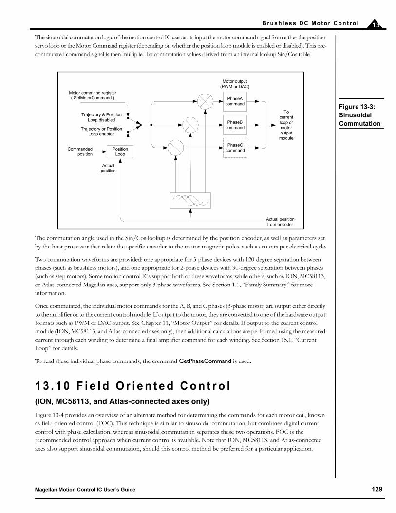
B r u s h l e s s D C M o t o r C o n t r o l 13
The sinusoidal commutation logic of the motion control IC uses as its input the motor command signal from either the position servo loop or the Motor Command register (depending on whether the position loop module is enabled or disabled). This pre-commutated command signal is then multiplied by commutation values derived from an internal lookup Sin/Cos table.
The commutation angle used in the Sin/Cos lookup is determined by the position encoder, as well as parameters set by the host processor that relate the specific encoder to the motor magnetic poles, such as counts per electrical cycle.
Two commutation waveforms are provided: one appropriate for 3-phase devices with 120-degree separation between phases (such as brushless motors), and one appropriate for 2-phase devices with 90-degree separation between phases (such as step motors). Some motion control ICs support both of these waveforms, while others, such as ION, MC58113, or Atlas-connected Magellan axes, support only 3-phase waveforms. See Section 1.1, “Family Summary” for more information.
Once commutated, the individual motor commands for the A, B, and C phases (3-phase motor) are output either directly to the amplifier or to the current control module. If output to the motor, they are converted to one of the hardware output formats such as PWM or DAC output. See Chapter 11, “Motor Output” for details. If output to the current control module (ION, MC58113, and Atlas-connected axes only), then additional calculations are performed using the measured current through each winding to determine a final amplifier command for each winding. See Section 15.1, “Current Loop” for details.
To read these individual phase commands, the command GetPhaseCommand is used.
1 3 . 1 0 F i e l d O r i e n t e d C o n t r o l(ION, MC58113, and Atlas-connected axes only)
Figure 13-4 provides an overview of an alternate method for determining the commands for each motor coil, known as field oriented control (FOC). This technique is similar to sinusoidal commutation, but combines digital current control with phase calculation, whereas sinusoidal commutation separates these two operations. FOC is the recommended control approach when current control is available. Note that ION, MC58113, and Atlas-connected axes also support sinusoidal commutation, should this control method be preferred for a particular application.
PhaseAcommand
Motor command register( SetMotorCommand )
PhaseBcommand
Trajectory & Position Loop disabled
Position Loop
Actual position from encoder
PhaseCcommandCommanded
position
Actualposition
Motor output(PWM or DAC)
To current loop or motor output module
Trajectory or Position Loop enabled
Figure 13-3: Sinusoidal Commutation
Magellan Motion Control IC User’s Guide 129

B r u s h l e s s D C Mo t o r C o n t r o l13
Compared to sinusoidal commutation, FOC uses an entirely different algorithmic method to determine the phase command for each motor winding. Instead of separating the phase lookup and current control operations as sinusoidal commutation does, it combines them and “re-references” them to what are known as D (direct torque) and Q (quadrature torque) reference frames. This difference in approach provides FOC with performance advantages over sinusoidal commutation at high motor speeds. At lower speeds there is very little performance difference between these two techniques.
Like sinusoidal control, FOC uses as its command input the motor command signal from either the position servo loop or the motor command register (depending on whether the position loop and trajectory modules are enabled or disabled). In addition to the motor command, however, FOC utilizes analog input signals to determine the instantaneous current flow through two of the three motor coils and combines this with the motor’s rotor position to determine exact output commands for each motor coil.
These calculations and subsequent update of the phase commands are performed at 20 kHz, regardless of the motion control IC’s PWM output rate, which can be either 20 kHz, 40 kHz, or 80 kHz in the case of the MC58113. See Section 11.5, “Setting PWM Frequency” for details on setting the PWM rate.
To enable field oriented control mode, the command SetCurrentControlMode should be used with an argument of FOC. The value set using this command can be read back using GetCurrentControlMode.
1 3 . 1 0 . 1 F O C A l g o r i t h m
Figure 13-5 details the algorithmic flow of the FOC controller. For each current loop (D & Q), three parameters are set by the user, Kp, Ki, and Ilimit. Two of these are gain factors for the PI (proportional, integral) controller that comprises the heart of the FOC controller, and the other is a limit for the integral contribution. These three parameters have the following ranges and formats.
Te r m N a m e R e p r e s e n ta t i o n & R a n g e
KpD, KpQ D, Q proportional gain unsigned 16 bits (0 to 32,767)KiD, KiQ D, Q integral gain unsigned 16 bits (0 to 32,767)IlimitD, IlimitQ D, Q integration limit unsigned 32 bits (0 to 2,147,483,647)
Motor Command
Q Loop Error
Transform
PI
InverseTransform
A Output+-
PI+-
B Output
Phase A Current
Phase B Current
Position Encoder
0 (zero)
D Loop Error
Figure 13-4: Control Flow Of FOC Control
130 Magellan Motion Control IC User’s Guide

B r u s h l e s s D C M o t o r C o n t r o l 13
To set any of these parameters, the command SetFOC is used. To read back these parameters, the command GetFOC is used. The values set using this command are buffered and may be activated using the Update command. See Section 6.1, “Parameter Buffering” for details.
Determining correct parameters for the FOC controller gains can be done in a number of ways. The easiest is to utilize the auto-tuning facility provided within PMD’s Pro-Motion software package. Parameters derived using this procedure may or may not be optimized for your system.
Another method is through trial and error using the Magellan’s built-in trace facility. Finally, it is possible to model your system and determine the best settings through simulation or analysis; however, a discussion of this approach is beyond the scope of this manual.
1 3 . 1 0 . 2 R e a d i n g F O C L o o p Va l u e s
To facilitate tuning, there are a number of internal FOC loop values that can be read back as well as traced. To read back these values the command GetFOCValue is used. To specify these values for trace during automatic trace capture see the Magellan Motion Control IC Programmer’s Command Reference.
Please note that it is the responsibility of the user to determine the suitability of all parameters, including those determined by auto-tuning, for use in a given application.
Clarke,Park
Transform
InversePark
Transform
BOutput
AOutput
Phase A Actual Current
0 (zero)+
-
QError QOutput
DError
QFeedback
DOutput
DFeedbackPosition Encoder
MotorCommand
QReference
2
DReference
+-
__..
+
KpQ
__..X +
X
64
KiQZ
-1
ILimitQ
X 256
__..
256
+
KpD
__..X +
X
64
KiDZ
-1
ILimitD
X 256
__..
256
Phase B Actual Current
Figure 13-5: Algorithmic Flow Of FOC Controller
Magellan Motion Control IC User’s Guide 131
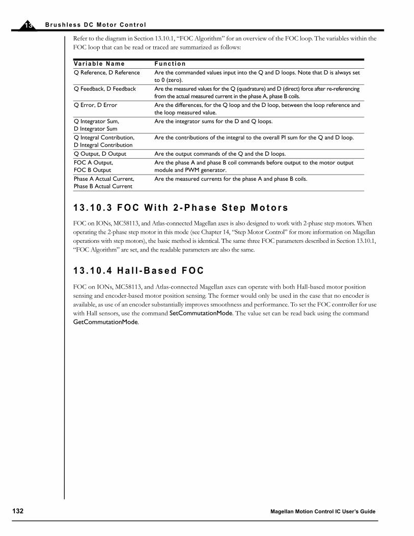
B r u s h l e s s D C Mo t o r C o n t r o l13
Refer to the diagram in Section 13.10.1, “FOC Algorithm” for an overview of the FOC loop. The variables within the FOC loop that can be read or traced are summarized as follows:
1 3 . 1 0 . 3 F O C W i t h 2 - P h a s e S t e p M o t o r s
FOC on IONs, MC58113, and Atlas-connected Magellan axes is also designed to work with 2-phase step motors. When operating the 2-phase step motor in this mode (see Chapter 14, “Step Motor Control” for more information on Magellan operations with step motors), the basic method is identical. The same three FOC parameters described in Section 13.10.1, “FOC Algorithm” are set, and the readable parameters are also the same.
1 3 . 1 0 . 4 H a l l - B a s e d F O C
FOC on IONs, MC58113, and Atlas-connected Magellan axes can operate with both Hall-based motor position sensing and encoder-based motor position sensing. The former would only be used in the case that no encoder is available, as use of an encoder substantially improves smoothness and performance. To set the FOC controller for use with Hall sensors, use the command SetCommutationMode. The value set can be read back using the command GetCommutationMode.
Va r i a b l e N a me F u n c t i o n
Q Reference, D Reference Are the commanded values input into the Q and D loops. Note that D is always set to 0 (zero).
Q Feedback, D Feedback Are the measured values for the Q (quadrature) and D (direct) force after re-referencing from the actual measured current in the phase A, phase B coils.
Q Error, D Error Are the differences, for the Q loop and the D loop, between the loop reference and the loop measured value.
Q Integrator Sum, D Integrator Sum
Are the integrator sums for the D and Q loops.
Q Integral Contribution, D Integral Contribution
Are the contributions of the integral to the overall PI sum for the Q and D loop.
Q Output, D Output Are the output commands of the Q and the D loops.FOC A Output, FOC B Output
Are the phase A and phase B coil commands before output to the motor output module and PWM generator.
Phase A Actual Current,Phase B Actual Current
Are the measured currents for the phase A and phase B coils.
132 Magellan Motion Control IC User’s Guide

14
1 4 . S t e p M o t o r C o n t r o lIn This ChapterOverviewEncoder FeedbackStall DetectionPulse & Direction Motor ControlMicrostepping Motor Control
1 4 . 1 O v e r v i e w
Magellan Motion Control ICs provide a number of special features for support of step motors. These include pulse and direction output, microstep signal generation, and a programmable holding current. Broadly speaking, two types of step motors are supported, pulse and direction motors and microstepping motors. Pulse and direction motors are step motors that are driven by an amplifier that accepts pulse and direction input signals. Microstepping motors are motors that are connected to an amplifier that controls the current through each phase explicitly, much like the way a brushless DC motor is controlled.
Overall, the control features of the Magellan when used with a step motor are similar to that used with servo motors. In particular trajectory generation, breakpoints, trace, and a number of other features are entirely unaffected by choice of motor type. The primary differences between servo motors and step motors however is that there is no position loop module used for step motors and that motor output signal generation differs from that of servo motors in some respects.
There are also a number of other features that are similar in concept, but different in implementation between servo motors and step motors. Motion error, which is equivalent to stall detection for step motors, is an example of this.
All of these differences will be explained in the upcoming sections of this chapter.
MC58000 Motion Control IC users are able to select between pulse and direction and microstepping motor modes. Thischoice will affect amplifiers interfacing and a number of other functions. MC55000 ICs are dedicated to pulse anddirection output, and external amplifiers should be chosen accordingly. ION uses a microstepping motor mode.However, since the amplifier is located internally, there are no external amplifier choice issues.
When used with Atlas amplifiers, Magellan can drive step motors either in pulse and direction mode or via the SPI Atlasbus. Between these two modes SPI Atlas is recommended because the SPI bus provides a much greater level ofinformation flow including safety-related information and the ability to select a wide range of control features. Whenused in pulse & direction mode the Atlas must first be configured by the user via SPI Atlas mode and then switched topulse & direction signal mode. Once in pulse & direction mode, SPI communication is not available.
Magellan Motion Control IC User’s Guide 133

S t e p M o t o r C o n t r o l14
1 4 . 1 . 1 Tr a j e c t o r y C o n t r o l U n i ts
For servo motors, the units for measuring position are encoder steps, and for time they are cycles. For step motors, position unitsare measured as either steps or microsteps, depending on whether the motor type is pulse and direction step motor, ormicrostepping motor. The following table lists various commands and their corresponding units.
1 4 . 2 E n c o d e r F e e d b a c k
For MC50000, each step motor axis supports position feedback in one of the two standard ways, either by incremental encoder input, or parallel-word input. See Chapter 10, “Encoder Interfacing” for more information on position feedback. The command SetEncoderSource selects the type of position feedback. If no position feedback is used (something that is not unusual for step motors), then a value of none should be entered using SetEncoderSource. Doing so will allow the position feedback value to be ignored, thereby disabling stall detection, a feature that will be discussed in an upcoming section.
ION can input position using incremental encoder information only. See the ION Digital Drive User’s Manual for details on interfacing to incremental quadrature encoders.
Regardless of the input method, most encoder commands operate as for servo motors. For example the current position is retrieved using the command GetActualPosition, the position capture location is retrieved using GetCaptureValue, and the AdjustActualPosition and SetActualPosition commands may be used to alter the current position. The default units of this command are encoder counts. To simplify program design and debugging, actual position units can be changed to steps/microsteps. This is done using the command SetActualPositionUnits. The following table lists the affected commands.
The SetActualPositionUnits command also affects the units of the trace variable Actual Position.
In many step motor systems, the ratio of steps to encoder counts is not necessarily exactly one. Magellan accommodates this by allowing the ratio of encoder counts to steps to be explicitly specified using the command SetEncoderToStepRatio. This value can be read back using the command GetEncoderToStepRatio.
If the units are set to counts, then the actual position commands are referenced to the encoder. If the units are set to steps, then the encoder input is converted to steps using the value specified by GetEncodertoStepRatio command.
C o m m a n d S e r v o a x e s M i c r o s t e p p i n g a x e s P u l s e & D i r e c t i o n a x e s
Set/GetPosition counts microsteps stepsSet/GetVelocity counts/cycle microsteps/cycle steps/cycleSet/GetAcceleration counts/cycle2 microsteps/cycle2 steps/cycle2
Set/GetDeceleration counts/cycle2 microsteps/cycle2 steps/cycle2
Set/GetJerk counts/cycle3 microsteps/cycle3 steps/cycle3
Set/GetStartVelocity - microsteps/cycle steps/cycleGetCommandedPosition counts microsteps stepsGetCommandedVelocity counts/cycle microsteps/cycle steps/cycleGetCommandedAcceleration counts/cycle2 microsteps/cycle2 steps/cycle2
Set/GetPositionErrorLimit counts microsteps stepsGetPositionError counts microsteps steps
C o m m a n d P o s i t i o n U n i ts = c o u n ts P o s i t i o n U n i ts = s t e ps
Set/GetActualPosition counts steps/microstepsAdjustActualPosition counts steps/microstepsGetCaptureValue counts steps/microsteps
134 Magellan Motion Control IC User’s Guide
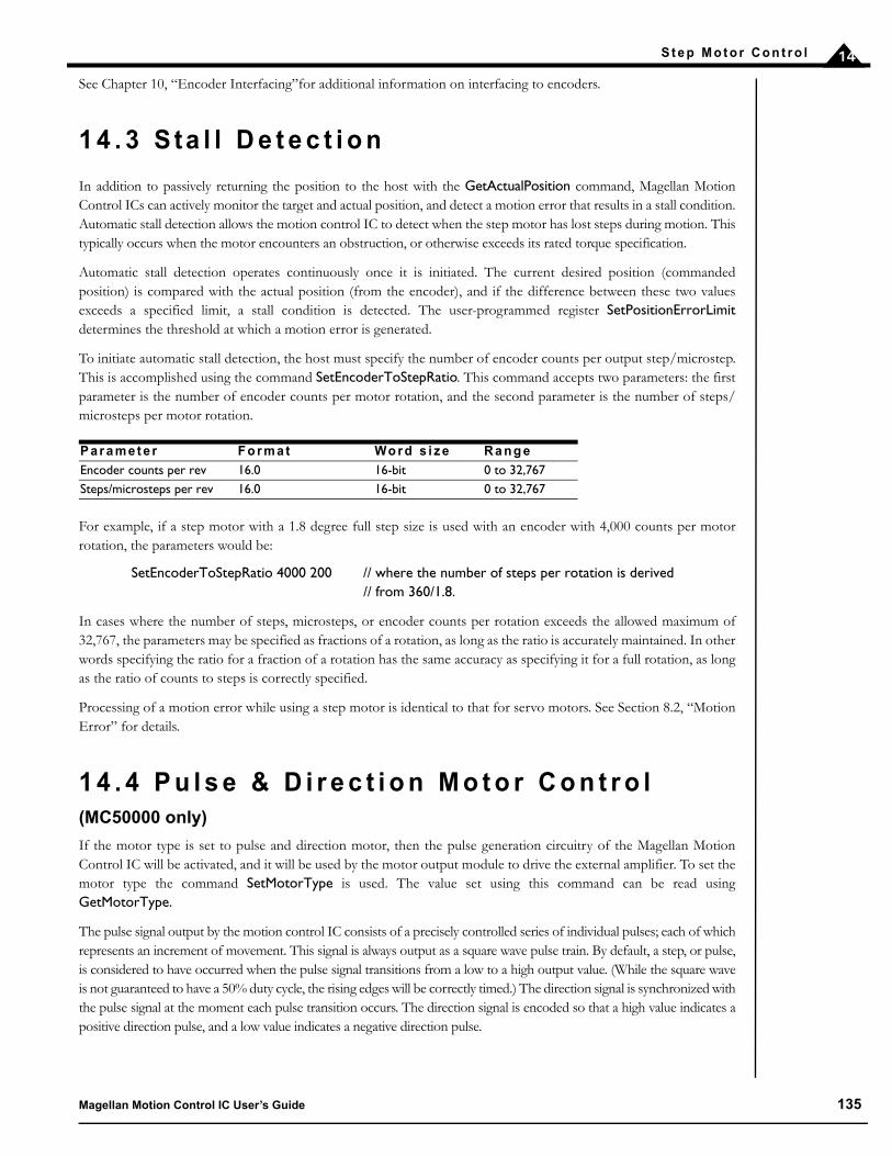
S t e p M o t o r C o n t r o l 14
See Chapter 10, “Encoder Interfacing”for additional information on interfacing to encoders.
1 4 . 3 S ta l l D e t e c t i o n
In addition to passively returning the position to the host with the GetActualPosition command, Magellan MotionControl ICs can actively monitor the target and actual position, and detect a motion error that results in a stall condition.Automatic stall detection allows the motion control IC to detect when the step motor has lost steps during motion. Thistypically occurs when the motor encounters an obstruction, or otherwise exceeds its rated torque specification.
Automatic stall detection operates continuously once it is initiated. The current desired position (commandedposition) is compared with the actual position (from the encoder), and if the difference between these two valuesexceeds a specified limit, a stall condition is detected. The user-programmed register SetPositionErrorLimitdetermines the threshold at which a motion error is generated.
To initiate automatic stall detection, the host must specify the number of encoder counts per output step/microstep.This is accomplished using the command SetEncoderToStepRatio. This command accepts two parameters: the firstparameter is the number of encoder counts per motor rotation, and the second parameter is the number of steps/microsteps per motor rotation.
For example, if a step motor with a 1.8 degree full step size is used with an encoder with 4,000 counts per motorrotation, the parameters would be:
SetEncoderToStepRatio 4000 200 // where the number of steps per rotation is derived// from 360/1.8.
In cases where the number of steps, microsteps, or encoder counts per rotation exceeds the allowed maximum of32,767, the parameters may be specified as fractions of a rotation, as long as the ratio is accurately maintained. In otherwords specifying the ratio for a fraction of a rotation has the same accuracy as specifying it for a full rotation, as longas the ratio of counts to steps is correctly specified.
Processing of a motion error while using a step motor is identical to that for servo motors. See Section 8.2, “MotionError” for details.
1 4 . 4 P u l s e & D i r e c t i o n M o t o r C o n t r o l(MC50000 only)
If the motor type is set to pulse and direction motor, then the pulse generation circuitry of the Magellan MotionControl IC will be activated, and it will be used by the motor output module to drive the external amplifier. To set themotor type the command SetMotorType is used. The value set using this command can be read usingGetMotorType.
The pulse signal output by the motion control IC consists of a precisely controlled series of individual pulses; each of whichrepresents an increment of movement. This signal is always output as a square wave pulse train. By default, a step, or pulse,is considered to have occurred when the pulse signal transitions from a low to a high output value. (While the square waveis not guaranteed to have a 50% duty cycle, the rising edges will be correctly timed.) The direction signal is synchronized withthe pulse signal at the moment each pulse transition occurs. The direction signal is encoded so that a high value indicates apositive direction pulse, and a low value indicates a negative direction pulse.
P a r a m e t e r F o r m a t Wo r d s i z e R a n g e
Encoder counts per rev 16.0 16-bit 0 to 32,767Steps/microsteps per rev 16.0 16-bit 0 to 32,767
Magellan Motion Control IC User’s Guide 135

S t e p M o t o r C o n t r o l14
The rate of pulse output is usually determined by the particular trajectory profile parameters being requested by thehost processor. However the Magellan Motion Control ICs support several ranges of pulse generation, to maximizeaccuracy for a given speed range. The overall pulse generation range can be specified using the commandSetStepRange. The following table shows the values and resultant step ranges available using this command.
The ranges in the preceding table show the maximum and minimum ranges which can be generated by the motioncontrol IC for the specified mode. For example, if the desired maximum step rate is 200 Ksteps per second, then theappropriate setting is SetStepRange 4.
For full-step and half-step applications, as well as for pulse and direction applications which will have a maximum velocity of 38 Ksteps/sec, SetStepRange 8 should be used. For applications requiring higher pulse rates, one of the higher speed ranges should be specified.
A different step range can be programmed for each axis. To read the current step range setting, use the commandGetStepRange.
1 4 . 5 M i c r o s t e p p i n g M o t o r C o n t r o lIf the motor type is set to microstepping motor, rather than pulse and direction signals, multi-phase output signals will begenerated for each axis set to this mode. Typical step motors have two phases, but some have three. MC58000 except MC58113supports two or three phase drive, while ION and MC58113 supports only two-phase. To set the motor type the commandSetMotorType is used. The value set using this command can be read using GetMotorType.
Note that for step motor ION Digital Drives, the motor type is automatically set to 2-phase microstepping. It is notnecessary to specify the motor type manually.
C o m m a n d F r e q u e n c y r a n g e o f o u t p u t p u l s e s
SetStepRange 1 0 to 4.98 M steps per secondSetStepRange 4 0 to 622.5 K steps per secondSetStepRange 6 0 to 155.625 K steps per secondSetStepRange 8 0 to 38.90625 K steps per second
The maximum pulse output rate on the MC58113 is 1.0 Msteps per second. On the MC55110 and MC58110 it is 100k steps per second. On all of these devices the SetStepRange command cannot be used.
136 Magellan Motion Control IC User’s Guide

S t e p M o t o r C o n t r o l 14
Figure 14-1 shows an overview of the control flow of the microstepping scheme.
Similar to sinusoidal commutation, the microstepping portion of the motion control IC generates a sinusoidalwaveform with a number of distinct output values per full step (one full step is one quarter of an electrical cycle). Thenumber of microsteps per full step is set using the command SetPhaseCounts. The parameter used for this commandrepresents the number of microsteps per electrical cycle (four times the desired number of microsteps). For example,to set 64 microsteps per full step, the command SetPhaseCounts 256 should be used. The maximum number ofmicrosteps that can be generated per full step is 256, resulting in a maximum parameter for this command of 1024.
The output frequency of the microstepping signals are controlled by the trajectory generator, while the Motor Commandregister controls the amplitude of the microstepping signals. To set this register use the command SetMotorCommand. A valuebetween 0 and 32,767 is set, representing an amplitude of zero to 100 percent. Since SetMotorCommand is double buffered,it requires an Update or a breakpoint to occur before it takes effect. This feature can be advantageous when the motor powerchanges are to be synchronized with other profile changes, such as at the start or the end of a move.
As described in a subsequent section, a special holding command limit can also be defined to allow different output levels foractive and non-active operational modes of the motor. This is useful for reducing heat output while the motor is not moving.
Step motor Atlas amplifiers that are connected to the Magellan by the SPI Atlas bus provide microstepping controlof the step motor. Two phase step motors only are supported, and the motor type should be specified as “step” ratherthan micrsotepping using the SetMotorType command.
1 4 . 5 . 1 M i c r o s t e p p i n g Wa v e f o r m s
For MC58000, two microstepping motor types with associated waveforms are provided, one appropriate for traditional two-phase step motors with 90 degrees of separation between phases and one appropriate for three-phase step motors with 120degree separation between phases. ION, MC58113, and Atlas-connected axes provide only two-phase microstep operation. Tospecify one of these two motor types the command SetMotorType is used. To read the value set using this command, useGetMotorType.
Figure 14-1: Microstepping Waveform Generation
Phase Acommand
Motor command register( SetMotorCommand )
Phase Bcommand
Trajectory generator
X
X
To current loop or motor output module
Magellan Motion Control IC User’s Guide 137

S t e p M o t o r C o n t r o l14
In addition, various motor output modes are available with different motor types. The following table summarizes this.
For specific pin assignments of the PWM and DAC motor output signals, see the Magellan Motion Control IC Electrical Specifications.
Figure 14-2 illustrates the phase A/phase B/phase C signals for a two-phase step motor, and the phase A/phase Bsignals for a three-phase step motor.
M o t o r t y p e M o t o r o u t p u t m o d e N u m b e r o f p h a s e s i g n a l s & n a m e
2-phase microstepping PWMSign/Mag 2 (A, B)2-phase microstepping PWM High/Low 2 (A, B)2-phase microstepping DAC 2 (A, B)3-phase microstepping PWM50/50 3 (A, B, C)3-phase microstepping PWM High/Low 3 (A, B, C)3-phase microstepping DAC 2 (A, B)step SPI Atlas 2 (four signal Atlas SPI bus)
0 64 128 192 256
2-Phase Microstepping
320
Phase A Phase B
Phase A Phase B Phase C
3-Phase Microstepping
Microsteps
120°
90°
Figure 14-2: Microstep-ping Wave-forms
138 Magellan Motion Control IC User’s Guide

S t e p M o t o r C o n t r o l 14
1 4 . 5 . 2 H o l d i n g C u r r e n t F u n c t i o n s
In addition to the standard pulse and direction output signals, MC50000 processors provide a signal output for each axis known as the AtRest signal, which indicates when the trajectory generator is in motion. This signal can be useful when interfacing with amplifiers that support a separate torque output level during motion as opposed to while it is holding (not moving).
For ION and MC58000 processors used with microstepping motor mode, a related facility exists to allow a specific holding current to be specified. Normally, the drive current used during microstepping operation motion is specified using SetMotorCommand. If desired, it is possible to have the output waveform be limited to a lower level while the motor is at rest. This current limit value can be set using the command SetHoldingCurrent. To read the value set use the command GetHoldingCurrent. Note that the value specified represents the limit of the output current while the motor is in a holding condition. For example if the current value normally output specified using SetMotorCommand is already lower than the at rest current limit, the lower motor command value will be used.
Whether represented as an AtRest signal, or output as a motor command reduction, the holding current condition will go active when the trajectory generator velocity is zero for a user-programmable amount of time. This parameter, if set to a non-zero value, allows a delay to be introduced between the time the trajectory finished, and the external signal goes active. Typically this is used to allow the motor to settle or come to a complete stop. This time delay can be set using the command SetHoldingCurrent. The value specified can be read back using GetHoldingCurrent.
A bit indicating whether the axis is currently in the holding condition or not is available in the Drive Status register. To read this register use the command GetDriveStatus.
1 4 . 5 . 3 F i e l d O r i e n t e d C o n t r o l a n d C u r r e n t C o n t r o l
For ION, MC58113, and Atlas-connected Magellan axes, current control of the step motor is achieved using either a field-oriented control technique, or a current control technique. See Section 13.10, “Field Oriented Control” for a detailed description of field-oriented control, and see Section 15.1, “Current Loop” for a detailed description of Magellan’s current loop. To select field oriented control or current control the command SetCurrentControlMode is used. The value set can be read back using GetCurrentControlMode.
Once the overall current control mode has been selected, the specific loop gain and other parameters can be specified.
When the current loop is enabled, MotorCommand defines the amplitude of the phase current as a percentage offull-scale.
Determining correct parameters for the FOC or current control modules can be done in a number of ways. The easiest is to utilize the auto-tuning facility provided within PMD’s Pro-Motion software package. Parameters derived using this procedure may or may not be optimized for your system.
Another method is through trial and error using the Magellan’s built-in trace facility. Finally, it is possible to modelyour system and determine the best settings through simulation or analysis; however, a discussion of this approach isbeyond the scope of this manual.
Please note that it is the responsibility of the user to determine the suitability of all parameters, including those determined by auto-tuning, for use in a given application.
Magellan Motion Control IC User’s Guide 139

S t e p M o t o r C o n t r o l14
This page intentionally left blank.
140 Magellan Motion Control IC User’s Guide

15
1 5 . D r i v e C o n t r o lIn This ChapterCurrent Loop Current Loop Parameters Enabling and Disabling Current LoopCurrent FeedbackReading Current Loop ValuesDrive Safety Feature OverviewOvercurrent SenseOvertemperature SenseOvervoltage SenseUndervoltage SenseCurrent FoldbackDrive Enable SignalFaultOut SignalDrive Fault Status RegisterAtlas-Specific CommandsSetting Atlas Initialization Configuration
(ION, MC58113, and Atlas-connected Magellan axes only)
In addition to profiling, servo control, and other standard Magellan motion functions, ION, MC58113, and Atlas-connected axes provide digital current and drive control features. These additional capabilities comprise a complete drive capability for the Magellan IC architecture.
Digital current control is a technique used for DC brush, brushless DC, and step motors for controlling the current through each winding of the motor. By controlling the current, response times improve, motor efficiency can be increased, and motion smoothness can improve.
The digital current loop utilizes the desired current for each motor winding along with the actual measured current, which is input by analog feedback into the motion IC. This desired current and measured current are then subtracted to develop a current error, which is passed through a PI (proportional, integral) filter to generate an output voltage for each motor coil. The output command for each coil is then passed through additional motor output logic to generate the precise PWM (pulse width modulation) timing outputs signals, which are connected to external switching drives.
In addition to digital current control, ION, MC58113, and Atlas-connected axes integrate a number of drive safety features such as overcurrent sense, overtemperature sense, overvoltage sense, undervoltage sense, and others. These features will be described later in this chapter.
Magellan Motion Control IC User’s Guide 141

D r i v e C o n t r o l15
1 5 . 1 C u r r e n t L o o p
Figure 15-1 provides an overview of the current control loop for each phase of motor axis. For single-phase motors such as DC brush, one current loop per axis is used. For 3-phase brushless DC motors, two current loops are used, one for the A phase and one for the B phase, and the voltage of phase C is driven using the formula C = –(A+B), reflecting the fact that current entering any two coils must exit from the third. When driving 2-phase step motors, two current loops are used, one for the phase A coil, and the other for the phase B coil.
For safety reasons the default status of the current loop module as well as motor output module after power-on is disabled. To enable (or disable) current control as well as motor output, use the command SetOperatingMode.
There are two overall types of current control provided. The first is Field Oriented Control. See Section 13.10, “Field Oriented Control” for a description. The other method is referred to as “current loop” and is an alternate current control method that can be used with both single phase and multi-phase motors. See Section 15.2, “Current Loop Parameters” for more information.
DC brush motors can use current control, however they cannot use FOC. To select which type of current control will be used, use the command SetCurrentControlMode. To read the value set using this command, use GetCurrentControlMode. If FOC is selected, then Section 15.2, “Current Loop Parameters” through Section 15.5, “Reading Current Loop Values” do not apply.
1 5 . 2 C u r r e n t L o o p P a r a m e t e r s
To control the current loop correctly, three parameters are set by the user, Kpcurrent, Kicurrent, and Ilimitcurrent. Two
of these are gain factors for the PI (proportional, integral) controller, and the other is a limit for the integral contribution. These three parameters have the following ranges and formats:
To set any of these three parameters, the command SetCurrentLoop is used. To read back these parameters, the command GetCurrentLoop is used. Note that for multi-phase motors, the values for the phase A and B loops can be
Te r m N a m e R e p r e s e n ta t i o n & R a n g e
Kpcurrent Current loop proportional gain Unsigned 16 bits (0 to 32,767)
Kicurrent Current loop integrational gain Unsigned 16 bits (0 to 32,767)
Ilimitcurrent Current loop integration limit Unsigned 16 bits (0 to 32,767)
Figure 15-1: Current Loop Control Flow
Phase A Actual Current
Phase A Error
Phase A OutputMotor Command
or Phase A Command
Phase A Reference
2
÷
+
KpCurrentA
X +
X
64
KiCurrentA
ILimitCurrentA
X 256
256
Integral Contribution
-+ ÷
Z-1
÷
142 Magellan Motion Control IC User’s Guide

D r i v e C o n t r o l 15
set independently while for single-phase DC brush motors, only the phase A loop parameters are used. The values set using this command are buffered, and may be activated using the Update command. See Section 6.1, “Parameter Buffering” for details.
Determining correct parameters for the current loop controller gains can be done in a number of ways. The easiest is to utilize the auto-tuning facility provided within PMD’s Pro-Motion software package. Parameters derived using this procedure may or may not be optimized for your system but will be a good starting point for most applications .
Another method is through trial and error using the Magellan’s built-in trace facility (see Section 8.8, “Trace Capture” for details). Finally, it is possible to model your system and determine the best settings through simulation or analysis; however, a discussion of this approach is beyond the scope of this manual.
1 5 . 3 E n a b l i n g a n d D i s a b l i n g C u r r e n t L o o p
If during normal operation the current loop is disabled, then the output from the previous module will pass directly to the motor output module, with no current control being performed. The most common use of this configuration is to run the drive in voltage mode, which may be useful under some conditions for calibration or testing. Use the command SetOperatingMode to enable or disable the current loop module.
1 5 . 4 C u r r e n t F e e d b a c k
For proper current loop operation feedback signals must be provided to the Magellan IC representing the current flowing through the motor coils. These signals are encoded as analog voltage levels, from 0.0V to 3.3V at the Magellan IC. The more accurate and noise-free these signals are, the higher the performance of the current loop will be.
For ION and Atlas-connected axes the current feedback signals are provided by dedicated circuitry located internal to the drive. For the MC58113 the motor’s instantaneous current readings are provided via up to four signals depending on the motor type being controlled. These signals are Current1A, Current1B, Current1C, and Current1D. MC58113 expects the external circuitry to provide leg current signals, meaning ground-referenced current readings through the lower legs of the bridge. See the MC58113 Electrical Specifications for details and complete example schematics.
1 5 . 5 R e a d i n g C u r r e n t L o o p Va l u e s
To facilitate tuning, there are a number of internal current loop values that can be read back as well as traced. To read back these values the command GetCurrentLoopValue or GetFOCValue is used. To specify these values for trace during automatic trace capture, see the Magellan Motion Control IC Programmer’s Command Reference.
Please note that it is the responsibility of the user to determine the suitability of all parameters, including those determined by auto-tuning, for use in a given application.
Magellan Motion Control IC User’s Guide 143

D r i v e C o n t r o l15
The variables within the current loop that can be read or traced are summarized in the following table. Refer to Figure 15-1 for an overview of the current loop.
1 5 . 6 D r i v e S a f e t y F e a t u r e O v e r v i e w
In addition to current control, a number of amplifier control features are provided that improve safety or reduce external circuitry required to build a complete drive.
The subsequent sections of this chapter describe these features.
1 5 . 7 O v e r c u r r e n t S e n s e
The ION, MC58113, and Atlas-connected Magellans support automatic detection of major amplifier, voltage supply, or other electrical hardware problems. These serious fault conditions are described in the following table:
Va r i a b l e N a me F u n c t i o n
Phase A Reference, Phase B Reference
Brushless DC & microstepping motor:These registers hold the commanded (reference) currents for the phase A and phase B coils. DC brush motor:Phase A Current holds the commanded (reference) current for the motor.
Phase A Current, Phase B Current Brushless DC & microstepping motor:These registers hold the measured currents for the phase A and phase B coils. DC brush motor:Phase A Current holds the measured current for the motor.
Phase A Error, Phase B Error Brushless DC & microstepping motor:These registers hold the difference between the current loop reference and the measured current value (Phase A Current, Phase B Current).DC brush motor:The Phase A Error register holds the difference between the current refer-ence and the measured current value (Phase A Current).
Phase A Integrator Sum, Phase B Integrator Sum
Brushless DC & microstepping motor:These registers hold the sum of the integrator for the phase A and B current loops.DC brush motor:Phase A Integrator Sum holds the sum of the integrator for the current loop
Phase A Integral Contribution,Phase B Integral Contribution
Brushless DC & microstepping motor:These registers hold the overall contribution of the integrator for the phase A and B current loops.DC brush motor:Phase A Integral Contribution holds the overall contribution of the integra-tor for the current loop
Phase A Output, Phase B Output Brushless DC & microstepping motor:These registers hold the output command for the phase A and B current loop.DC brush motor:Phase A Output holds the output command for the current loop.
F a u l t N a m e D e s c r i p t i o n
Overcurrent An overcurrent fault across the drive output is detected. This fault occurs when the motor, the wiring leading from the drive, or the internal circuitry of the drive becomes short circuited.
144 Magellan Motion Control IC User’s Guide

D r i v e C o n t r o l 15
Any of these faults will cause the following sequence of events:
The Magellan’s motor output module is disabled, thereby halting further motor output.
Depending on the state of the FaultOut mask the FaultOut signal may be set to active (see Section 15.14, “Drive Fault Status Register” for details).
The cause of the fault is saved in non-volatile memory (ION only).
The motion control IC may enter a special state that requires that power be cycled (ION only). If this is the case, until power is cycled, no commands will be accepted and no further motion processing of any kind occurs. Check the ION Digital Drive User’s Manual for details.
To recover from this condition, the user should determine the nature of the fault using the GetDriveFaultStatus command and, once the cause of the fault has been corrected, use the ClearDriveFaultStatus command to clear the condition. Although it is not required that this command be sent, it is often useful for safety and diagnostic reasons.
1 5 . 8 O v e r t e m p e r a t u r e S e n s e
ION, MC58113, and Atlas-connected axes provide the capability to continually monitor drive temperatures using sensors. A programmable value set using the command SetOvertemperatureLimit (ION) or SetDriveFaultParameter (MC58113 and Atlas-connected axes) is compared to a value read from a temperature sensor, and if the value read from the sensor exceeds the programmed threshold, an overtemperature fault occurs. To read the value set the command GetOverTemperatureLimit (ION) or GetDriveFaultParameter (MC58113 and Atlas-connected axes) is used.
ION temperature readings occur via a thermistor located inside the physical ION drive unit. The actual value read represents the temperature inside the ION drive. Similarly, the temperature reading for Atlas-connected axes is located inside the Atlas unit. For MC58113, the temperature is input by analog signal via the Temperature input pin. Therefore the physical location of the sensor, if one is used, is determined by the user. Most users will locate the temperature sensor on or near the amplifier, but this is not required.
When used with ION and Atlas, the value set using this threshold must have a value less than or equal to the rated maximum for the drive. See the ION Digital Drive User’s Manual or Atlas Digital Amplifier’s User’s Manual for details.
When used with ION and Atlas, the value set using the SetOverTemperatureLimit command is in units of deg C/256. For example, a value of 12,800 indicates a threshold of 50 deg C. With the MC58113 there is no explicit
Ground fault This fault indicates that one or more of the motor connections are short circuited to the power supply ground. This fault occurs when the motor, the wiring leading from the digital drive to the motor, or the internal circuitry of the drive becomes short circuited to ground (ION only).
Electrical fault This fault indicates that the supply voltage for drive logic components external to the motion control IC is too low or too high. This can occur when there is a prob-lem with the circuitry external to the motion control IC, or when the motion con-trol IC has experienced anomalous electrical conditions such as excessive supply voltage or excessive voltage on input or output signals (ION only).
Overcurrent, ground fault, and electrical faults are serious conditions and warrant the utmost precaution before repowering and re-enabling the drive. It is the responsibility of the user to determine the cause and appropriate corrective action for an electrical fault. Refer to the ION Digital Drive User’s Manual, the Atlas Digital Amplifier User’s Manual, or the MC58113 Electrical Specifications for additional details on the procedure used to recover from an electrical fault.
F a u l t N a m e D e s c r i p t i o n
Magellan Motion Control IC User’s Guide 145

D r i v e C o n t r o l15
correspondence between the values read and the actual temperature in deg C, since this may vary with the sensor being used.
An overtemperature fault will cause the following events:
The motor output module is automatically disabled.
The overtemperature bit in the Event Status register is set active.
To recover from this condition, the user should determine the reason for the fault and correct accordingly. It is always the responsibility of the user to maintain safe operating conditions of the drive and associated electronics. Once this has occurred, the overtemperature bit of the Event Status register should be cleared. This can be accomplished using ResetEventStatus. The normal operation of the control modules can then be restored using RestoreOperatingMode.
The instantaneous status of the overtemperature threshold comparison can be read using the command GetDriveStatus. If the overtemperature fault condition is still occurring at the time the overtemperature bit of the Event Status register is cleared, this bit will immediately be set again, and the recovery sequence must be executed again.
To read the current value of the temperature sensor, the command GetTemperature is used.
1 5 . 9 O v e r v o l ta g e S e n s e
ION, MC58113, and Atlas-connected axes provide the capability to sense overvoltage conditions in the incoming main bus voltage. A programmable threshold set using the command SetBusVoltageLimits (ION) or SetDriveFaultParameter (MC58113 and Atlas-connected Magellan axes) is compared to the value read from the drive DC bus supply, and if the value read exceeds the programmed threshold, an overvoltage fault occurs. To read the value set, the command GetBusVoltageLimits (ION) or GetDriveFaultParameter (MC58113 and Atlas-connected Magellan axes) is used.
For ION and Atlas-connected axes the bus voltage readings and limits are provided by dedicated circuitry internal to the drive. For the MC58113 the bus voltage is input via the BusVoltage pin in connection with appropriate external circuitry.
The value set using this threshold must have a value equal to or less than a prescribed maximum for the drive. See the user’s manual for the ION or Atlas drive product you are using for details. For the MC58113 there is no specific maximum setting because the scaling of the voltage will depend on the external circuitry used.
An overvoltage fault will cause the following events:
The motor output module is disabled.
The bus voltage sense bit in the Event Status register becomes active
To recover from this condition, the user should determine the reason for the fault and correct accordingly. It is always the responsibility of the user to maintain safe operating conditions for the ION drive and associated electronics. Once this has occurred, the bus voltage bit of the Event Status register should be cleared. This can be accomplished using ResetEventStatus. The normal operation of the control modules can then be restored using RestoreOperatingMode.
Overtemperature faults indicate that the internal safe limits of the drive temperature range has been exceeded. This potentially serious condition can result from incorrect motor connections or from excessive torque demands placed on the drive.
146 Magellan Motion Control IC User’s Guide

D r i v e C o n t r o l 15
The instantaneous value of the overvoltage threshold comparison can be read using the command GetDriveStatus. If the overvoltage fault condition is still occurring while the overvoltage bit of the Event Status register is being cleared, this bit will immediately be set again, and the recovery sequence described above must be executed again.
The drive supply voltage can be monitored using the GetBusVoltage command. It returns the current supply voltage reading.
1 5 . 1 0 U n d e r v o l ta g e S e n s e
ION, MC58113, and Atlas-connected amplifiers provide a capability similar to the overvoltage sense except that it monitors undervoltage. To set the programmable threshold the command SetBusVoltageLimits (ION) or SetDriveFaultParameter (MC58113 and Atlas-connected Magellan axes) is used. This value is compared to the value read from the drive DC bus, and if the value read is less than the programmed threshold, an undervoltage fault occurs.
The value set using this threshold must have a value equal to or less than a prescribed maximum for the drive. See the user's manual for the ION or Atlas drive product you are using for details. To read the value set, the command GetBusVoltageLimits (ION) or GetDriveFaultParameter (MC58113 and Atlas-connected Magellan axes) is used.
For ION and Atlas-connected axes the bus voltage readings and limits are provided by dedicated circuitry internal to the drive. For the MC58113 the bus voltage is input via the BusVoltage pin in connection with appropriate external circuitry.
Threshold units, recovery procedure, and all other aspects of this feature are the same as for overvoltage sense except that the bit status location in the Drive Fault Status register is different. And just as for overvoltage conditions, it is the user's responsibility to determine the seriousness of, and appropriate response to, an undervoltage condition.
1 5 . 11 C u r r e n t F o l d b a c k
ION, MC58113, and Atlas-connected axes support a current foldback feature, sometimes referred to as an I2t foldback, which can be used to protect the drive output stage or motor windings from excessive current. I2t current foldback works by integrating, over time, the difference of the square of the actual motor current and the square of the user-settable continuous current limit.
When this integrated value reaches a user-settable energy limit, the axis goes into current foldback. The axis will stay in foldback until the integrator returns to zero. When in current foldback, the current is clamped to the continuous current limit value, although it is also possible to program additional actions such as disabling motor output.
To set the event action associated with a current foldback event the command SetEventAction is used.
Each ION and Atlas drive has particular default values as well as maximum allowed settings for the continuous current limit and energy limit. These values are designed to protect the drive from excessive heat generation. See the ION Users manual for detailed information or the Atlas Digital Amplifier Complete Technical Reference. For the MC58113 there are no specific maximum settings because the limits will depend on the external circuitry used.
Setting continuous current limit and energy limit to less than the maximum supported by the ION drive or Atlas is useful if the required current limit is due to the motor, rather than to the ION drive. Continuous Current Limit and Energy Limit can be set using the command SetCurrentFoldback. The values set using this command can be read back using GetCurrentFoldback.
The instantaneous state of current foldback (whether the foldback limit is active or not) is available in the Drive Status register and can be read using the command GetDriveStatus. In addition, if a foldback event has occurred, this event is recorded in the Event Status register and can be read back using GetEventStatus.
Magellan Motion Control IC User’s Guide 147

D r i v e C o n t r o l15
As detailed in Section 8.1, “SetEventAction Processing” if desired, an event action can be programmed for current foldback using the command SetEventAction. Whether this is appropriate must be determined by the user.
Example I2T calculations
A particular motor has an allowed continuous current rating of 3 amps. In addition, this motor can sustain a temporary current of 5 amps for 2 seconds.
In this example the continuous current limit would be set to 3 amps, and the energy limit would be set to:
Energy Limit = (peak current2 - continuous current limit2) * time
Energy Limit = (5A2 - 3A2) * 2 Sec
Energy Limit = 32A2Sec
To determine the actual parameter values that should be sent to the SetCurrentFoldback command, consult the ION Users Manual or the Atlas Digital Amplifier User’s Manual for the particular drive that you are using.
1 5 . 1 2 D r i v e E n a b l e S i g n a l
ION, the MC58113, and Atlas amplifiers support an Enable input signal that must be active for proper operation. This signal is useful for allowing external hardware to indicate a fault to the drive and thereby automatically shutting it down. The signal has an active low interpretation.
If the Enable signal becomes inactive (goes high) the following events occur:
The motor output module is disabled.
the disable bit in the Event Status register becomes active. For Atlas, the drive exception bit of the Event Status register becomes active and the Disabled bit of the Drive Fault Status register is set.
To recover from this condition, the user should determine the reason for the enable becoming inactive, and correct accordingly. It is always the responsibility of the user to maintain safe operating conditions of the drive and associated electronics. Once this has occurred, the appropriate bit of the Event Status register should be cleared. This can be accomplished using ResetEventStatus. The normal operation of the control modules can then be restored using RestoreOperatingMode.
If the /Enable signal is still inactive while the disable or drive exception bit of the Event Status register is being cleared, this bit will immediately be set again, and the recovery sequence must be executed again.
The status of the /Enable signal can be read using the command GetSignalStatus.
1 5 . 1 3 F a u l t O u t S i g n a l
ION and MC58113 support a FaultOut signal, which is used to indicate an occurrence of one or more of the faults indicated in the previous section. This signal is always active high, its sense cannot be changed using the command SetSignalSense. It is possible to use this signal to indicate additional motion control IC conditions. In particular, any bit
Current foldback, when it occurs, may indicate a serious condition affecting motion stability, smoothness, and per-formance. It is the responsibility of the user to determine the appropriate response to a current foldback event.
148 Magellan Motion Control IC User’s Guide

D r i v e C o n t r o l 15
condition of the Event Status register may be used to trigger activation of the fault signal. This is done using the command SetFaultOutMask. The value set using this command can be read back using GetFaultOutMask.
For example, programming SetFaultOutMask with a value of 20 (14 hex) configures the FaultOut signal to be driven high upon a Motion Error, BreakPoint1, or an electrical fault.
For Atlas-connected axes, the Atlas units’ FaultOut signal is also programmable, but the conditions are internal to Atlas only. For more information on how to program the FaultOut behavior of the Atlas see the Atlas Digital Amplifier Complete Technical Reference.
1 5 . 1 4 D r i v e F a u l t S ta t u s R e g i s t e r
To simplify recovery from a drive fault, as well as to read other drive-related faults, Magellan provides a Drive Fault Status register that can be read using the command GetDriveFaultStatus. The bits in this register operate similarly to the bits in the Event Status register in that they are set by the motion control IC, and cleared by the user. The following table indicates the contents of this register:
To clear the bits in this register the command ClearDriveFaultStatus is used. For MC58113 and Atlas-connected axes at least one read of this register via the GetDriveFaultStatus command must occur before bits can be cleared.
For ION, unlike other registers in the Magellan Motion Control IC, a portion of the contents of this register are saved after a power cycle. Thus electrical faults (bits 0, 1, 2, and 4), which cause all communications with the drive to cease, and require the unit power to be cycled, can still be diagnosed once the condition has been corrected and the unit has
B i t N a m e D e s c r i p t i o n
0 Overcurrent Set 1 to indicate an electrical fault due to a short circuit or overload in the drive output.1 Ground fault Set 1 to indicate an electrical fault due to a short in the drive output (ION only).2 External logic fault Set 1 to indicate an electrical fault located in the drive's output circuitry (ION only).3 Mode mismatch Set 1 to indicate that Atlas has received a torque or voltage command at a time when this
is not a valid operation. (Atlas-connected axes only)4 Internal logic fault Set 1 to indicate an electrical fault located in the drive's internal logic circuitry (ION only).5 Overvoltage Set 1 to indicate an overvoltage condition of the external bus voltage input.6 Undervoltage Set 1 to indicate an undervoltage condition of the external bus voltage input.7 Disabled Set 1 to indicate that the amplifier enable signal input is inactive (Atlas-connected axes
only). 8 Foldback Set 1 to indicate that a current foldback event has occurred.9 Overtemperature Set 1 to indicate that an overtemperature fault has occurred.10 SPI checksum error Set 1 to indicate that the attached Atlas detected a checksum error or a disable command.
(Atlas-connected axes only)11 Communication
watchdogSet 1 to indicate that the drive has not received an expected transmission of data.Typically used to flag conditions where the motion controller stops sending commands to the ampli-fier. (Atlas-connected axes only)
12 Reserved May contain 0 or 113 PWMOutputDisable Set to 1 to indicate that the PWMOutputDisable signal input is active (MC58113 only).14 SPI checksum error Set 1 to indicate that Magellan has detected a checksum error while sending a communica-
tions packet to the drive. (Atlas-connected axes only)15 Motor type mismatch Set 1 to indicate that the motor type that Magellan is set to does not match the motor type
of the attached Atlas amplifier. (Atlas-connected axes only)
Magellan Motion Control IC User’s Guide 149

D r i v e C o n t r o l15
been powered up normally. The Overvoltage and Undervoltage status bits are not saved but rather are cleared during a power cycle so they always reflect the latest voltage fault status.
1 5 . 1 5 A t l a s - Sp e c i f i c C o m m a n d s
Atlas functions are seamlessly accessible from Magellan so that the user need not be versed in the internal details of the SPI Atlas protocol. Magellan accomplishes this by interpreting incoming commands from the host and routing them to internal destinations, or to appropriate Atlases depending on the nature of the host-requested function.
Although this automatic function distribution is convenient, there may be times when it is desirable for the host to send commands directly to the Atlas amplifier. To accomplish this, bit 5 of the Magellan command word is set active, and the appropriate axis number that corresponds to the Atlas being communicated to must be specified in the Magellan command word. Refer to the Magellan Motion Control IC Programmer’s Command Reference for complete information on Magellan host I/O protocol.
Figure 15-2 shows this, showing a host -requested command being sent to the Magellan, which in turn forwards the command as well as its response back to the Magellan, which in turn provides the requested information to the host.
For a complete description of Atlas commands, see the Atlas Digital Amplifier Complete Technical Reference.
In the case that an Atlas is connected to an MC58113, the Atlas will drive the above Drive Fault Status register flags, and the related MC58113 signals will not be utilized.
STEP 2:Magellanforwards to Atlas
STEP 1:Host sendsdrive-related
command
STEP 4:Magellan
provides data to host
MC58000
Magellan®Parallel I/O,Serial,
or CANbus
SPIAtlasBus
GetFOC Atlas®
Digital Amplifier
Host Controller
Atlas®
Digital Amplifier
GetFOC
Parallel I/O,Serial,
or CANbus
SPIAtlasBus
MC58000
Magellan®
Host Controller
STEP 3:Magellan
retrieves data from Atlas
Parallel I/O,Serial,
or CANbus
SPIAtlasBus
Return PacketHost
Controller
Atlas®
Digital Amplifier
MC58000
Magellan®
Parallel I/O,Serial,
or CANbus
SPIAtlasBus
Return PacketHost
Controller
Atlas®
Digital Amplifier
MC58000
Magellan®
Figure 15-2: Host To Magellan To Atlas Packet Processing
150 Magellan Motion Control IC User’s Guide

D r i v e C o n t r o l 15
1 5 . 1 6 S e t t i n g A t l a s I n i t i a l i z a t i o n C o n f i g u r a t i o n
Atlas drives allow many parameters, such as current gains, over and under temperature thresholds, and many other quantities to be stored permanently into an on-unit NVRAM (non volatile RAM). When stored on the unit, these parameters are automatically loaded and no longer need to be sent by the host. This is useful to reduce the number of startup host commands that must be sent to get the system ready for operation.
It is generally simplest to utilize PMD’s Windows-based Pro-Motion program to configure the NVRAM memory. Nevertheless, it is also possible for the host to send these programming commands directly. Consult the Atlas Digital Amplifier Complete Technical Reference for detailed information on how this can be accomplished.
Magellan Motion Control IC User’s Guide 151

D r i v e C o n t r o l15
This page intentionally left blank.
152 Magellan Motion Control IC User’s Guide

16
1 6 . M e m o r y B u f f e r s a n d I / OIn This ChapterMemory ConfigurationUser I/O
1 6 . 1 M e m o r y C o n f i g u r a t i o n
Magellan Motion Control ICs are capable of accessing memory buffers for the storage of trace data or to be used forgeneric storage purposes. For MC50000 users except MC58113 this memory, if used, is located external to the MagellanIC and must be designed into the card by the user. Correspondingly the size of this memory buffer is determined by theuser.
For card users, the amount of memory is fixed. See the Magellan Motion Controller Card User’s Guide for details. ION andMC58113 users also have a fixed amount of buffer storage, however located internal to the Magellan IC. See the IONDigital Drive User’s Manual or the MC58113 Electrical Specifications for details.
1 6 . 1 . 1 M e m o r y B u f f e r s
Magellan buffers are a contiguous block of memory with a base address and length. Once a buffer’s base address andlength have been defined, data values may be written to and read from the buffer.
When defining memory buffers the memory space is treated as a sequence of 32-bit memory locations. Each 32-bit valuetakes up two 16-bit memory locations in physical memory, with the high word of the 32-bit word stored in the uppermemory location and the low word stored in the lower memory location. Buffer base addresses and lengths both dealwith 32-bit quantities and therefore must be doubled to get the corresponding physical addresses.
When defining memory buffers the motion control IC will allow any values to be used for the base address and length,as long as the values result in legal addresses. Legal memory addresses range from 0 to 3FFF FFFFh (corresponding tophysical address 7FFF FFFEh). Unless the full two gigawords of physical memory are present, it is possible to map abuffer to a memory location that does not contain physical memory.
In addition to the base address and length, each memory block maintains a read index and a write index. The read indexmay be assigned a value between 0 and L-1 (where L is the buffer length). It defines the location from which the nextvalue will be read. Similarly, the write index ranges from 0 to L-1 and defines the location at which the next value willbe written. When a value is read from the memory buffer, the read index is automatically incremented, thus selectingthe next value for reading. The write index is incremented whenever a value is written to a buffer. If either index reachesthe end of the buffer, it is automatically reset to 0 on the next read/write operation.
1 6 . 1 . 2 M e m o r y B u f f e r C o m m a n d s
This section details host commands that set up, access, and monitor memory buffers. Note that for ION users, these commands are not necessary, as the location and size of the available buffer are already set.
SetBufferStart bufferID, address Sets the base address of a buffer. bufferID is a 16-bit integer in the range 0–31 that specifies the buffer to be mod-
Magellan Motion Control IC User’s Guide 153

M e m o r y B u f f e r s a n d I / O16
ified. The variable address is a 32-bit integer in the range 0 to 3FFF FFFFh that defines the new base address ofthe buffer.
The motion control IC adds address to the current buffer length (as set by the SetBufferLength instruction) toensure that the buffer will not extend beyond the addressable memory limit. If it would extend beyond the limit,the instruction is ignored and the instruction error bit is set..
GetBufferStart bufferID Returns the base address of the specified buffer.
SetBufferLength, bufferID, length Sets the length of a buffer. bufferID is a 16-bit integer in the range 0–31. length is a 32-bit integer in the range 1to 3FFF FFFFh.
The motion control IC adds length to the current buffer base address (as set by the SetBufferStart instruction)to ensure that the buffer will not extend beyond the addressable memory limit. If the buffer would extendbeyond the limit, the instruction is ignored and the instruction error bit is set.
GetBufferLength bufferID Returns the length of the specified buffer.
SetBufferReadIndex bufferID, index Sets the read index for the specified buffer. index is a 32-bit integer in the range 0 to length–1, where length isthe current buffer length. If index is not in this range, it is not set, and an instruction error is generated.
GetBufferReadIndex bufferID Returns the value of the read index for the specified buffer.
SetBufferWriteIndex bufferID, index Sets the write index for the specified buffer. index is a 32-bit integer in the range 0 to length–2, where length isthe current buffer length. If index is not in this range, it is not set, and an instruction error is generated.
GetBufferWriteIndex bufferID Returns the value of the write index for the specified buffer.
ReadBuffer bufferIDReturns a 32-bit value from the specified buffer. The location from which the value is read is determined by add-ing the base address to the read index. After the value has been read, the read index is incremented. If the resultis equal to the current buffer length, the read index is set to zero (0).
WriteBuffer bufferID, valueWrites a 32-bit value to the specified buffer. The location to which the value is written is determined by addingthe base address to the write index. After the value has been written, the write index is incremented. If the resultis equal to the current buffer length, the write index is set to zero (0).
1 6 . 2 U s e r I / O
Magellan ICs except MC58113 implement a peripheral device address space that is accessed with the ReadIO and WriteIO commands. This address space is used to access hardware peripherals external to the Magellan chipset. For a complete memory map of the peripheral address space see MC5X00 Series Electrical Specifications.
SetBufferStart and SetBufferLength reset the buffer indexes to zero (0).
154 Magellan Motion Control IC User’s Guide

M e m o r y B u f f e r s a n d I / O 16
ReadIO and WriteIO take an address parameter which is an offset from location 1000h of the motion control IC's hardware peripheral device address space.
The format and interpretation of the 16-bit data word are dependent on the user-defined device being addressed. User-defined I/O can be used to implement a number of features, including additional parallel I/O, flash memory for non-volatile configuration information storage, or display devices such as LED arrays.
Note that User I/O commands use a different signalling protocol and different timing than external memory access commands. (See the MC55000 Series Electrical Specifications or the MC58000 Series Electrical Specifications for details).
1 6 . 2 . 1 U s e r I / O C o m m a n d s
This section details host I/O commands that cause Magellan to access its peripheral device address space.
ReadIO addressReads one 16-bit word of data from the device at address, where address is an offset from location 1000h of themotion control IC's peripheral device address space.
WriteIO address, dataWrites one 16-bit word of data to the device at address, where address is an offset from location 1000h of themotion control IC's peripheral device address space.
Magellan Motion Control IC User’s Guide 155

M e m o r y B u f f e r s a n d I / O16
156 Magellan Motion Control IC User’s Guide
This page intentionally left blank.

Index
Numerics50/50 PWM mode 89AA/D converters 83abrupt stop 33absolute
encoder 14magnitude 88optical encoders 83
accelerationparameter 27slope 27value 27
active registers 47Activity Status register 55, 57actual motor position 35actual position 66, 82, 135
units 134additional trace data 68addressable memory
limit 154space 69
algorithmic initializationmode 124sequence 126
amplifierlinear 101switching 101
analogfiltering 82input 78reference signal 99, 101signal 78
analog-to-digital converter 14asynchronous
event notifications 114frame 111serial connection 110serial port 15, 105
at max velocity indicator 51at rest indicator 139
Atlas 16drive control 141field-oriented control 129traces 72
automatic stall detection 135auxiliary axis parameter 40axis
breakpoint 49input pin 77master 31output pin 77position 63settled 67slave 31source 49
Bbacklash 38bad checksum 109band-pass filter 41bi-directional parallel port 105binary-encoded position 15bi-quad 41
coefficient scaling 43coefficients 42output filter 41
bitevent status 51mask 48status 51
bitmasked value 75bit-oriented
fields 55status registers 55
bit-programmed word 124breakaway starting friction 125breakpoint 48, 66, 74
axis 49deactivate 51defined 52instruction 49level-triggered 50
Magellan Motion Control IC User’s Guide 157

158
number 49operations 55threshold triggered 50threshold-triggered 50updatemask 49
breakpoint 1 49breakpoint 2 49Brushless DC motor control 121
automatic phase correction 126encoder prescaler 128field oriented control 129number of phases 122overview 121phase counts 123phase initialization 123phase initialization programming 125phasing control modes 122sinusoidal commutation 128
bufferbase address 153length 154read index 154write index 154
bufferedcommands 47, 48operations 109
butterworth filter 42
CCAN 114
address 116interface 116interface layer 114interface protocol 114message 116network 116node ID 116notification 116
CAN 2.0Binterface 15network 114
CANOpen 114capture
received 74register 83
captured data 68, 73checksum 105, 109
byte 112calculation 112
invalid 112valid 112value 112
clear interrupt 75coefficients 42coil current distortion 99command
buffered 47, 48format 105, 111MultiUpdate 48packet 108, 112, 113packet fields 111packet sequence 106read 105update 48values 25write 105
commanded position 63, 66, 135commutation
angle 129error 74frequency 91rate 23reliability 126signals 122waveforms 122, 129
comparison value 49continuous data retrieval 68control modules 19control signals 107, 108controlled stop 33current
control 99foldback 74
custom filter 41cycle
frequency 23rate 23time 22timer 66
DDAC 15, 91
channels 97outputs 91signal timing 91values 91
Magellan Motion Control IC User’s Guide
databuffers 69collection synchronization 69frame format 111packet 112packet time limit 113trace operations 73traces 68transfer 105
dataless command 105DC servo motor output 100debugging 134deceleration slope 27defined breakpoint 52derivative term, servo loop 38differential line drivers/receivers 82digital
filtering 82motor output word 99, 101
directoutput bit 77set phase initialization 125
directionof motion 31signal, encoding 135
direction signal encoding 102disable 74disabling control modules 21drive control 141
current feedback 143current foldback 147disabling current loop 143dribe fault status register 149drive enable signal 148drive safety feature 144enabling current loop 143FaultOut signal 148overcurrent sense 144overtemperature sense 145overvoltage sense 146reading current loop lalues 143undervoltage sense 147
drive data 92drive exception 74Drive Status register 55, 58dual encoder
mode 39processing 40
dual encoder support 38dual loop processing 40
Eelectrical cycles 123electronic
gear profile 32gear profile mode 31gearing 25, 66
emergency stop 33EMF 89, 99enabling 86enabling control modules 21encode, incremental 83encoder
counts 126, 134modulus 84prescaler 128to step ratio 135
end-of-travel condition 63error
codes 112commutation 74instruction 74position 63
event 49event status 55
bit 51Event Status register 55, 75
clearing 75external
buffer memory 73peripherals 77quadrature decoder circuit 83
Ffalling edge 92feedback type 81filter
band-pass 41bi-quad output 41butterworth 42custom 41high-pass 41low-pass 41motor output 43parameters 37second-order butterworth 42
fixed-point representation 25
Magellan Motion Control IC User’s Guide 159

160
follow-on function 66full scale feedback range 83functional overview 14
Ggear ratio 32generic command packet sequence 106GetVersion command 24
Hhalf-bridge 97
driver 89Hall interpretation value 124Hall-based
initialization 123initialization sequence 125
hardware communication operation 106H-bridge
amplifiers 88device 99
high-pass filter 41high-speed position capture register 82home signal 82host
I/O commands 112, 153, 155instructions 28interrupt 66, 74interrupt events 74interrupt facility 116
host-specified profile parameters 26, 28
Iidle-line protocol 113in motion indicator 51incorrect command transfer 109incremental
encoder feedback 81encoder signals 14encoders 83feedback 82signals 14
index pulseinput 126phase correction 126signal 126
index signal 82inductance 99
initialization 124duration 125motor command value 125procedure 125
in-motionbit 66indicator 66
instantaneouscommanded profile values 25deceleration 33
instructionerror 56, 74error bit 154word 105
integrationlimit 38limit scaling 38term 38
interconnection diagram 14interconnections 13interface signals 109internal scaling factor 42interrupt 75
mask 75inverter circuitry 124inverting summing amplifier 91
Jjerk 29
KKi value 38Kout
parameter 38value 38
Kp 38
Llaser interferometer 14, 83level-triggered breakpoint 50limit
positive 74switch event 64, 66, 75switches 14
linearamplifier 99, 101interpolation 32
low pass filter 41, 99, 101
Magellan Motion Control IC User’s Guide

MMagellan family 11Magellan motion processing 16mask
interrupt 75sense 51trigger 50
masteraxis 31axis number 31mode 78
Matlab 42maximum position error 63memory buffer 68, 153microstepping
control flow 137output values 137signal output frequency 137signals, amplitude 137
microstepping motor output 98minimum timeout 113mode 25
master 78slave 78
modulo 84modulus 83
encoder 84motion
complete 74complete bit 66complete indicator 66error 14, 63, 74error bit 63error cause 63error recovery 63error status bit 63processor address 113profile 25profile complete 66
motion complete indicator 66motor
bias 43command output 88, 125command register 129, 130, 137command value 95limit 43output limit 43output options 87output waveform 95
phase angle 127phasing 125three-phase step 138two-phase step 138type 86
Motor Output module 86disabling 85
multi-drop idle-line mode 113multi-turn systems 83MultiUpdate command 48
Nnegative gear ratio value 32Negative Limit 74noise
pulses 82sources 82
non-buffered instruction 109notch filter 41notify mask 116
OOctave 42one-time trace mode 68op-amp circuit 100optional bias value 36output
clocking 92filter coefficients 42formats 88scale factor 36scaling factor 42
overshoot 28overtemperature fault 74over-travel 63
Ppacket 105, 112
command 112, 113data, limit time 113format 105response 111, 112
parallel portconfiguration 107control signals 108
parallel-bus interface 15
Magellan Motion Control IC User’s Guide 161

162
parallel-word 83feedback 81input 14input mechanism 83
parameterranges, filter 37traces 69
parity bit 111part numbers 16peripheral
bus 91read 84
phaseangle 123cycle 127
phase initialization 123, 125, 127algorithmic 123bit 126command 125direct-set 123Hall sensor-based 123
phase offsetregister 127value 127
phase referencing, commutation error 127phasing error 127phasing procedure 125PID
algorithm 36filter 15
PID-type servo filter 35point-to-point 15
configuration 114mode 110protocols 113serial mode 113
positionactual 135capture register 83commanded 135encoder 129error 63, 65error limit 65feedback value 84loop 35tracking 83wraparound 74
positivegear ratio value 32limit 74limit switch 64
pre-commutated command signal 129prescaler 128
function 128product summary 11profile 25
generator 28, 66generator registers 66parameters 25, 28
programmable tracking window 65programmed acceleration value 29proportional-integral-derivative algorithm 36pulse
output rate 136rate modes 103
Pulse & Direction signal, generation 102PWM 15
magnitude 88PWM frequency, setting 94PWM signal interpretation, setting 94
Qquadrature
counts 81data 82data stream 125incremental position 81
Rratio, encoder to step 135read
buffer 73command 105data 69index 73pointer 69
registercapture 83motor command 129phase offset 127position capture 83
Reset command 22resetting the loop rate 23resolver 14, 83, 125response packet 111, 112resynchronize 113
Magellan Motion Control IC User’s Guide

rising edge 92rolling
buffer 73trace mode 68
SS-curve
mode 30point-to-point 25point-to-point profile 28profile 29
second-order butterworth filter 42sense mask 51separate pulse rate modes 103serial
checksum 112data transfer 111, 117, 118hardware signals 112operations 113peripheral
interface 92Serial Peripheral Interface 117serial port, default configuration 110servo
filter 39loop 129, 130loop calculation rate 23parameter commands 48performance 65
set cycle time 22SetEventAction command 61settle
time 66, 67window 66, 67
settled indicator 67sign magnitude PWM 88signal
control 107encoded direction 135home 82index pulse 126interpretation 59parallel port control 108pre-commutated command 129
Signal Status mask 59Signal Status register 55, 59signed numerical value 88sinusoidal waveform generation 99, 137
slaveaxis 31mode 78
smooth stop 33source axis 49SPI
Atlas 93Atlas communications protocol 94Atlas, communications overview 93Atlas, functional overview 93communications 117communications overview 93DAC mode 92data 92output 92output pin 92
square wave pulse train 102, 135stall
condition 135detection 135
starting velocity 27status
bit 51event 55read operation 109registers, bit-oriented 55
step motorsupport 134three-phase 138two-phase 138
step motor control 133encoder feedback 134microstepping 136overview 133pulse & direction 135stall detection 135
stopabrupt 33bits 111command 66controlled 33emergency 33smooth 33
switching amplifier 99, 101synchronization
pin 78sample time 79
Magellan Motion Control IC User’s Guide 163

164
synchronizedmotion 78power changes 137
synchronizing multiple motion control ICs 79system overview 13
Tthree-phase
AC induction motor 100step motor 138
threshold triggered breakpoints 50Time register 23time slice 23timeout period 113trace
buffer 68, 69, 73buffer configuration 69capture 68capture overhead 22data 69data capture 68data retrieval 68data storage 153mode 72, 74period 74samples 73start 74start/stop 72stop 74
traceable parameter 69tracing
frequency 69system 69
trackingbit 65window 65window, size 65
trajectorygenerator 15, 25, 35, 47, 63generator registers 66motion 66parameters 25profile 66profile mode 47profile modes 25update rate 23
transfer protocols 15
transmissionerrors 112protocols 113
trapezoidalmode 30point to point 25point-to-point profile mode 26
trigger 49mask 50
triggering event 55two-phase step motor 138
Uupdate command 48User I/O 154
Vvalue
phase offset 127velocity
contouring 25starting 27
velocity-contouring profile mode 30
Wwaveform, magnitude 95write command 105write index 153
Magellan Motion Control IC User’s Guide

This page intentionally left blank.
165 Magellan Motion Control IC User’s Guide

Magellan Motion Control IC User’s Guide 166
For additional information, or for technical assistance,please contact PMD at (978) 266-1210.
You may also e-mail your request to [email protected]
Visit our website at http://www.pmdcorp.com
Performance Motion Devices80 Central Street
Boxborough, MA 01719


![[PPT]Ferdinand Magellan - Tripod.comwadd.tripod.com/Magellan.ppt · Web viewFerdinand Magellan By Taylor and Haley Magellan was born in spring in 1470. Magellan was killed in the](https://static.fdocuments.us/doc/165x107/5afc89fd7f8b9a814d8c3915/pptferdinand-magellan-viewferdinand-magellan-by-taylor-and-haley-magellan-was.jpg)