Loop Efficiency (Kempton) - nonstopsystems.comLoop Efficiency (Kempton) May 2006 14 Rho-Q Loop...
29
Loop Efficiency (Kempton) May 2006 1 Small Loop Antenna Efficiency By Mike Underhill - G3LHZ
Transcript of Loop Efficiency (Kempton) - nonstopsystems.comLoop Efficiency (Kempton) May 2006 14 Rho-Q Loop...

Loop Efficiency (Kempton) May 2006 1
Small Loop Antenna Efficiency
By Mike Underhill - G3LHZ

Loop Efficiency (Kempton) May 2006 2
Why Measure Antenna Efficiency?• Do we trust Simulations more than Measurements?• Can measurements ‘validate’ or ‘invalidate’ simulations? • What do we do if measurements disagree with simulation?
– Reject all measurements that do not fit?– Re-do the measurements until some do fit? – Find out how to upgrade the simulation?
• Can measurements confirm or reject ‘traditional theory’, such as the ChuWheeler Small Antenna limiting Q criterion?
• What should we do if measurements appear to contradict ‘Maxwell’s equations’?
• Is an ‘upgrade extension’ to Maxwell’s Equations:-– Impossible? – Forbidden?

Loop Efficiency (Kempton) May 2006 3
What is Antenna Efficiency? – 1 • The IEEE (USA) view is that ‘The Antenna Efficiency’ is the field strength
measured at a few wavelengths away from the antenna relative to the field strength computed from a formula.
• The formula predicts the field strength Ep in volts/metre at a distance R in metres from a from an antenna with Directivity (= gain assuming 100% efficiency) and input power P in watts as:
Ep = √(30×P×D)/R• If the measured field strength at the same distant point is Em the effficiency is
η = Em/Ep• In completely ‘free space’ this method is sound and predictably accurate. • Near the ground or in a cluttered or confined environment it is of very little use. It
then is prone to the following errors and uncertainties: – Ground loss under the antenna to about 1/6 of a wavelength (up to -15dB)– Ground loss under the field probe (up to -15dB). – Pattern distortion at both ends due to the presence of the ground. – 1/R becoming 1/√R for a low loss ground with a dominant surface wave.
Loop Efficiency (Kempton) May 2006 4
What is Antenna Efficiency? – 2
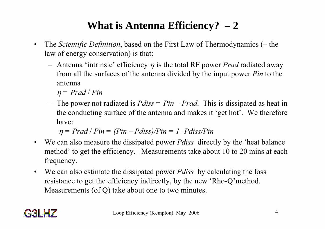
• The Scientific Definition, based on the First Law of Thermodynamics (– the law of energy conservation) is that:– Antenna ‘intrinsic’ efficiency η is the total RF power Prad radiated away
from all the surfaces of the antenna divided by the input power Pin to the antennaη = Prad / Pin
– The power not radiated is Pdiss = Pin – Prad. This is dissipated as heat in the conducting surface of the antenna and makes it ‘get hot’. We therefore have:η = Prad / Pin = (Pin – Pdiss)/Pin = 1- Pdiss/Pin
• We can also measure the dissipated power Pdiss directly by the ‘heat balance method’ to get the efficiency. Measurements take about 10 to 20 mins at each frequency.
• We can also estimate the dissipated power Pdiss by calculating the loss resistance to get the efficiency indirectly, by the new ‘Rho-Q’method. Measurements (of Q) take about one to two minutes.

Loop Efficiency (Kempton) May 2006 5
‘Heat Balance’ Measurement of Antenna Efficiency (as in Nov 2004 Radcom article on Loops)
• The RF power lost as ‘heat’ is the same as the DC power the loop required to raise the same or an exactly similar loop to the same temperature.
• The DC power heats a resistance wire inside the loop• Non-contact temperature measurement by Thermal
Camera (below) or CHY 110 non-contact thermometer (bottom right)
• Thermal picture is of Marc Harper.• Thermal emissivities of two loops are made equal by
black paint patches at measuring points on the loops.

Loop Efficiency (Kempton) May 2006 6
Thermal Camera Heat Balance Efficiency Results for 1m diameter Loop of 10mm
Plumbing Copper Tube
10.127.033.71.98 Frequency in MHz
90888674Efficiency in %

Loop Efficiency (Kempton) May 2006 7
Some New Heat Measurements• The First Law of Thermodynamics says that the power lost in an inefficient
antenna will be dissipated as heat. The antenna itself will get hot. • With high power to an inefficient loop “tuning for maximum smoke” can be
too true! • If loop efficiencies really were the 0.1 to10% that the critics claim, practically
all the RF input power would be dissipated in the loop (or loop capacitor) as heat.
• 150watts DC (14.0 V and 10.7A) into resistance wire in a 1m diameter loop of 10mm tube (in October 2004 RadCom) gave a temperature rise to 100°C. Ambient temperature was 14.0°C
• The temperature rise was 86°C (±1°C). The temperature rise is proportional to heat power lost for both radiation and convection.
• Therefore for 400 RF watts supplied and 396 watts dissipated in a 1% efficient loop, the loop temperature would be rise to 241°C and more for any joints and connecting wires.
Loop Efficiency (Kempton) May 2006 8
Some New Heat Measurements (continued)
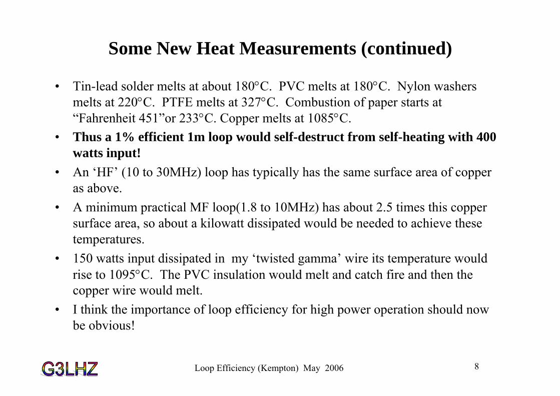
• Tin-lead solder melts at about 180°C. PVC melts at 180°C. Nylon washers melts at 220°C. PTFE melts at 327°C. Combustion of paper starts at “Fahrenheit 451”or 233°C. Copper melts at 1085°C.
• Thus a 1% efficient 1m loop would self-destruct from self-heating with 400 watts input!
• An ‘HF’ (10 to 30MHz) loop has typically has the same surface area of copper as above.
• A minimum practical MF loop(1.8 to 10MHz) has about 2.5 times this copper surface area, so about a kilowatt dissipated would be needed to achieve these temperatures.
• 150 watts input dissipated in my ‘twisted gamma’ wire its temperature would rise to 1095°C. The PVC insulation would melt and catch fire and then the copper wire would melt.
• I think the importance of loop efficiency for high power operation should now be obvious!

Loop Efficiency (Kempton) May 2006 9
Simple Rho-Q Method for Antenna Efficiency -1
• Once the measured Q of a loop is known its efficiency is easily found from its dimensions and the loop conductor resistivity ρ (rho).
• The efficiency is η =Rrad/Rtot = 1 - Rloss/Rtot = (1 - Q Rloss/Xl) (1)
• In the above we have used reactance Xl = 2πfL and Rtot=Xl/Q=2πfL/Q • The conductor loss Rloss is the “skin effect” loss of the loop conductor. • This can be found from the DC resistivity ρ of the loop conductor material,
the conductor length, the loop circumference Cir, and the conductor tube or wire effective diameter d.
• The skin effect loss resistance Rloss is proportional to the square root of the frequency and the square root of the DC resistivity ρ of the loop conductor
• The skin effect loss resistance for the loop is found to beRloss = √(0.4× fMHz× ρ)×Cir/d (2)
Loop Efficiency (Kempton) May 2006 10
Simple Rho-Q Method for Antenna Efficiency-2
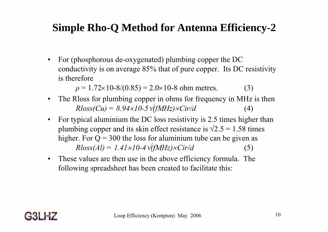
• For (phosphorous de-oxygenated) plumbing copper the DC conductivity is on average 85% that of pure copper. Its DC resistivity is therefore
ρ = 1.72×10⁻⁸/(0.85) = 2.0×10⁻⁸ ohm metres. (3)• The Rloss for plumbing copper in ohms for frequency in MHz is then
Rloss(Cu) = 8.94×10⁻⁵√(fMHz)×Cir/d (4)• For typical aluminium the DC loss resistivity is 2.5 times higher than
plumbing copper and its skin effect resistance is √2.5 = 1.58 times higher. For Q = 300 the loss for aluminium tube can be given as
Rloss(Al) = 1.41×10⁻⁴√(fMHz)×Cir/d (5)• These values are then use in the above efficiency formula. The
following spreadsheet has been created to facilitate this:

Loop Efficiency (Kempton) May 2006 11
Rho-Q Loop Efficiency Spreadsheet

Loop Efficiency (Kempton) May 2006 12
Rho-Q Loop Efficiency Spreadsheet
• The spreadsheet automates the Rho-Q method. • The loop dimensions are inserted in the blue
shaded boxes at the top. • The pairs of 3dB frequencies that are the Q
measurements are put in the two blue shaded columns at the left.
• All the un-shaded columns are outputs derived from these inputs.
• The formulas that determine these outputs are given in the top rows.
• The measurements shown in the spreadsheet are for the experimental 1m diameter loop of 10mm copper plumbing tube shown left.
• It has two twisted gamma matches of different lengths, switched at the bottom.
• Note that there is no significant difference in efficiency when a short twisted gamma feed is used (top set of measurements) or a long twisted gamma is used (bottom set of measurements).
• In fact efficiency is not in general altered by the type of feed used.

Loop Efficiency (Kempton) May 2006 13
Rho-Q Loop Efficiency Spreadsheet -2
• The results show that loop efficiency is not altered by the length of the twisted gamma match at any frequency. Further loop Q measurements of other loop feeds lead to the conclusion is that the type of loop feed does not alter loop efficiency in any significant way.
• Outputs enable the measured loop efficiency to be compared with the classical predictions
• They also include important loop design parameters such as:– Tuning capacitance values – Capacitor voltage for a given power
input – Loop current for a given power
input
Loop Efficiency (Kempton) May 2006 14
Rho-Q Loop Efficiency Spreadsheet -3
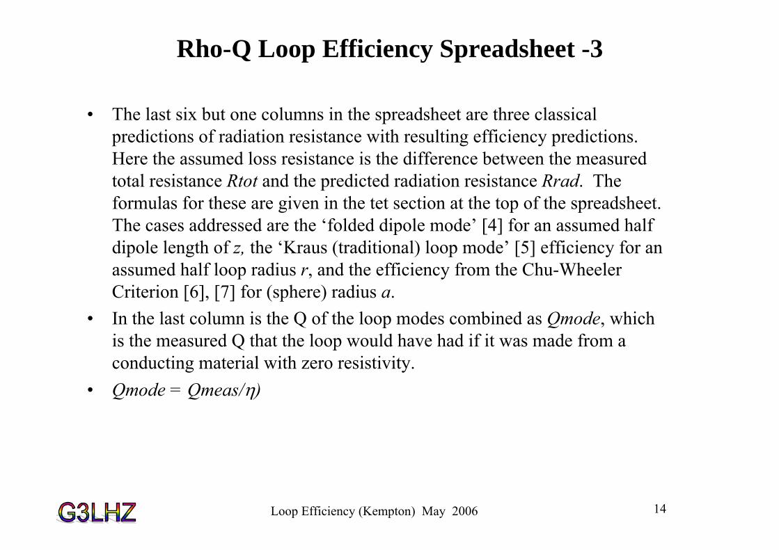
• The last six but one columns in the spreadsheet are three classical predictions of radiation resistance with resulting efficiency predictions. Here the assumed loss resistance is the difference between the measured total resistance Rtot and the predicted radiation resistance Rrad. The formulas for these are given in the tet section at the top of the spreadsheet. The cases addressed are the ‘folded dipole mode’ [4] for an assumed half dipole length of z, the ‘Kraus (traditional) loop mode’ [5] efficiency for an assumed half loop radius r, and the efficiency from the Chu-Wheeler Criterion [6], [7] for (sphere) radius a.
• In the last column is the Q of the loop modes combined as Qmode, which is the measured Q that the loop would have had if it was made from a conducting material with zero resistivity.
• Qmode = Qmeas/η)
Loop Efficiency (Kempton) May 2006 15
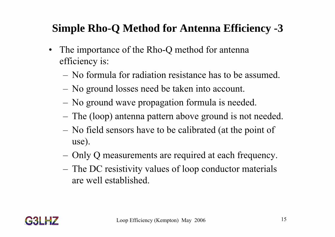
Simple Rho-Q Method for Antenna Efficiency -3
• The importance of the Rho-Q method for antenna efficiency is: – No formula for radiation resistance has to be assumed. – No ground losses need be taken into account. – No ground wave propagation formula is needed. – The (loop) antenna pattern above ground is not needed. – No field sensors have to be calibrated (at the point of
use). – Only Q measurements are required at each frequency. – The DC resistivity values of loop conductor materials
are well established.

Loop Efficiency (Kempton) May 2006 16
(G3LHZ) Mini-Midi Loop.
• The ‘mini-loop’ is vertical and the horizontal rectangular ‘midi-loop’ is 20 to 40m (0.25λto 0.5λ) perimeter at about 2m above ground. (Midi-Loop size is as recommended for the (MFJ) ‘Loop Tuner’.
• Bandwidth can be improved to 3% corresponding to a Q of 30 as tapping points are moved towards the capacitor.
• Power handling is at least doubled. • The SWR is raised towards 4:1 but any reasonable ATU can handle this witout having to
adjust the loop match.

Loop Efficiency (Kempton) May 2006 17
(G3LHZ) Mini-Midi Loop Example.
• The ‘mini-loop’ is an AMA5 vertical loop shown with two additional 1440pF Palstarcapacitors to tune optionally to 160 m
• The horizontal rectangular ‘midi-loop’ is 20 to 40m (0.25λ to 0.5λ) perimeter at about 2m above ground in apple trees. It is attached across the capacitor at top of the mini-loop.
• Protection and insulation for the apple tree branches and bamboo support is provided by plastic foam pipe insulation as shown.

Loop Efficiency (Kempton) May 2006 18
The Original G3LHZ IP-Quad
WiMo 2m Cross-polarised Antenna as on the GB4FUN Vehicle on 6/5/06 in Belfast.
Note the Driven Element!
‘The ip quad – a new versatile quad driven element’
by M. J. Underhill, G3LHZ, Radio Communication,
September 1976

Loop Efficiency (Kempton) May 2006 19
G3LHZ Diagonal IP-
Quad
First Reported in Technical Topics November 1976

Loop Efficiency (Kempton) May 2006 20
Centre-Line Tuned Loops
• Independent two frequency tuning.• Polarisation can be changed from horizontal to vertical by varying the tuning• When both ‘ports’ tuned to the same frequency the banwidth is nearly
doubled. • 1.7 m diameter loop of 10mm tube handled 550 watts on 160m. >3000pF
needed!
Loop Efficiency (Kempton) May 2006 21
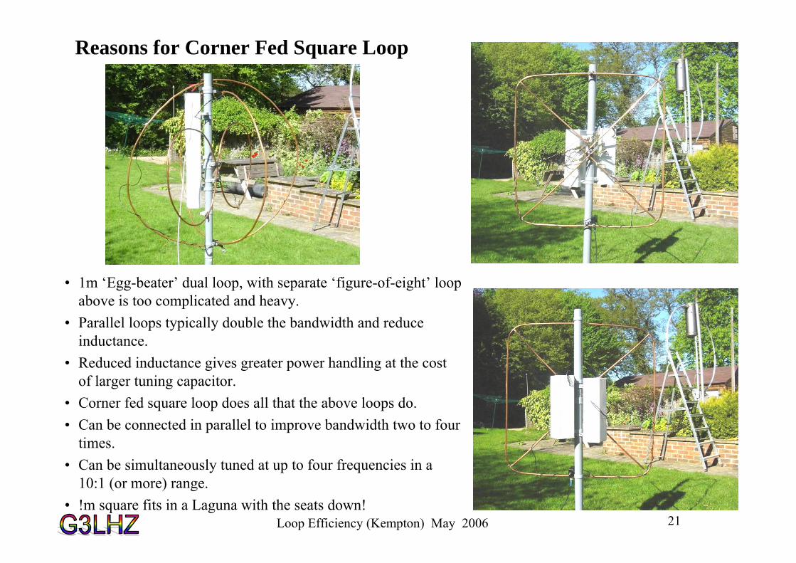
Reasons for Corner Fed Square Loop
• 1m ‘Egg-beater’ dual loop, with separate ‘figure-of-eight’ loop above is too complicated and heavy.
• Parallel loops typically double the bandwidth and reduce inductance.
• Reduced inductance gives greater power handling at the cost of larger tuning capacitor.
• Corner fed square loop does all that the above loops do.• Can be connected in parallel to improve bandwidth two to four
times.• Can be simultaneously tuned at up to four frequencies in a
10:1 (or more) range.• !m square fits in a Laguna with the seats down!
Loop Efficiency (Kempton) May 2006 22
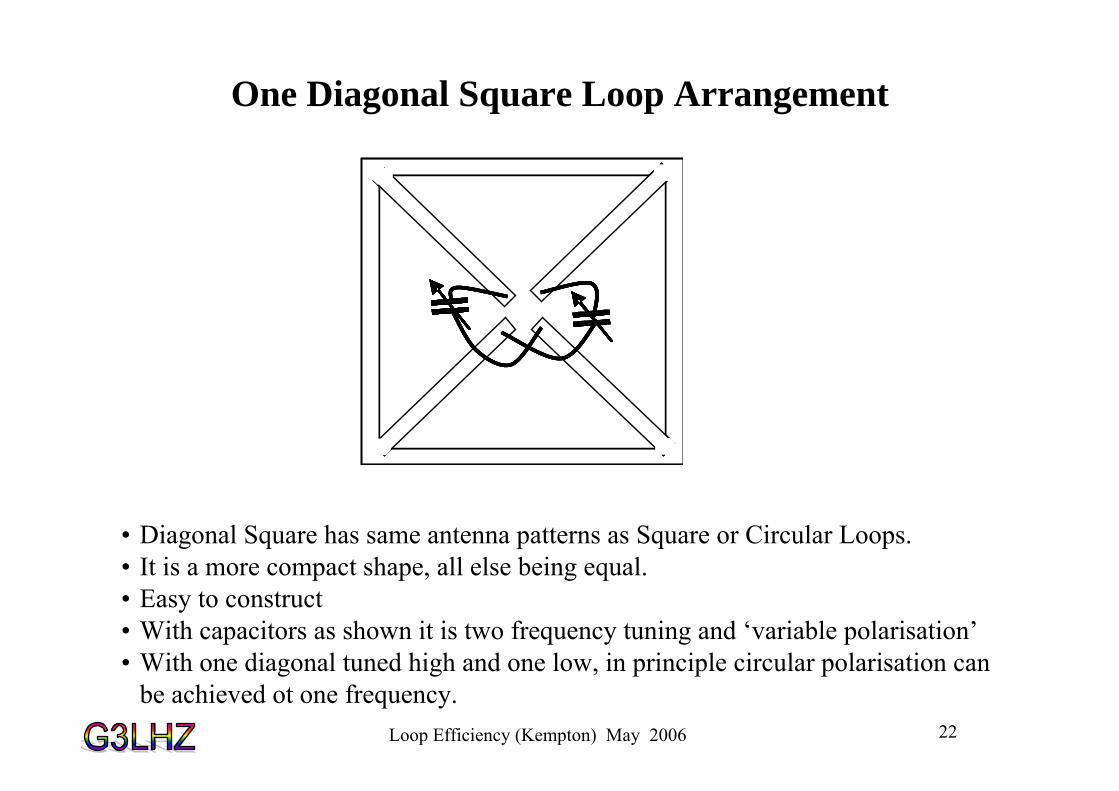
One Diagonal Square Loop Arrangement
• Diagonal Square has same antenna patterns as Square or Circular Loops. • It is a more compact shape, all else being equal. • Easy to construct• With capacitors as shown it is two frequency tuning and ‘variable polarisation’• With one diagonal tuned high and one low, in principle circular polarisation can
be achieved ot one frequency.
Loop Efficiency (Kempton) May 2006 23
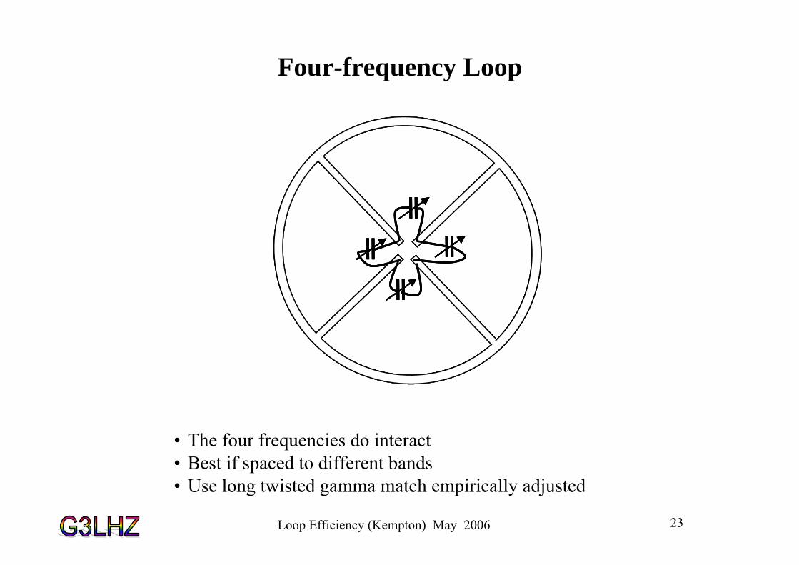
Four-frequency Loop
• The four frequencies do interact• Best if spaced to different bands• Use long twisted gamma match empirically adjusted

Loop Efficiency (Kempton) May 2006 24
Wider-Band High Power Loops
• 1m square loop of 10mm copper plumbing tube with about 2000pF capacitance to tune to 80m took 750 watts before flashover. (Used 2 Palstar 1440pF caps.)
• Did not self-destruct! • Q is about 140 which is typical for
this kind of loop arrangement. (Allows 3 to 4 times the power.)
• 1.7m diameter loop of 10mm copper plumbing tube with about 3300pF capacitance to tune to 160m took 550 watts with no sign of flashover or overheating.
• BW = 9.2 kHz• Q =215 which is typical for this
connection. (Allows about double the power)

Loop Efficiency (Kempton) May 2006 25
Loop Patterns – Mini-Loop on left. Midi-Loop on right
0
30
60
90
120
150
180
210
240
270
300
330
0.80.60.40.2
H-planeE-planeH-planeE-plane
rn
an
θ n
0
30
60
90
120
150
180
210
240
270
300
330
0.80.60.40.2
H-planeE-planeH-planeE-plane
rn
an
θ n
Mini-Loop Directive Gain = 1.5 = 1.76dBi Midi-Loop Directive Gain = 1.87 = 2.7dBi

Loop Efficiency (Kempton) May 2006 26
DEFINITIONS OF ANTENNA EFFICIENCY AND EFFECTIVENESS• 15 efficiency definitions = Pn/Pm
• P6 is power density in a given direction
•P6/P5 is the ‘directivity’ in that direction
•Important ratios are: ‘intrinsic efficiency = P3/P2’, ‘total antenna efficiency = P5/P2’ and ‘antenna gain = P6/P2.
•‘Intrinsic efficiency’ is important because it is little affected by the environment and is essentially the efficiency of the antenna in free space.
• It is the proportion of the input rf that just escapes the surface of the antenna and has not been dissipated as heat in the antenna conductor surfaces.
•Effectiveness = (Antenna gain from transmitter) /( Cost etc). It is qualitative!
•We need agreed standard definitions validated by measurements. For many years there has been much confusion and misunderstanding. The IEEE-Std 145-1993 on antenna efficiency has not helped
Antenna Matching Unit
Antenna‘Seen’ loss and radiation resistances
‘Unseen’ Environmental Losses
Antenna Radiation Pattern
P1, Power from transmitter
P2, Power into antenna & AMU Efficiency = P2/P1
P3, Antenna radiation & Intrinsic Efficiency = P3/P2
P6 = erp to Propagation Path & Antenna Gain = P6/P2
P4, Near-field radiation & Environmental Efficiency = P4/P2
P5, Total Antenna Radiation & Total Antenna Efficiency = P5/P2
Figure 1 Various losses and antenna efficiencies

Loop Efficiency (Kempton) May 2006 27
Where does the input power go? What are the patterns of ‘mini’ and ‘midi’ loops?
Radiation mechanisms of a small antenna over ground (loop at bottom left):1.Heat losses in antenna. 2. Direct radiation to sky-wave.3. Antenna mode losses from strong local coupling into ground . 4. Launching of two types of surface wave:
• Horizontal Sky-wave• Surface-ground-wave from
ground currents.5. Radiation of sky-wave from ground currents Radiating ground currents
Mode losses from strong local coupling into ground
Direct radiation of sky-wave from antenna.
Vertical
Horizontal sky-wave
Surface ground wave
Sky-wave from ground currents
How can we possibly define the IEEE efficiency of any small antenna on an absolute basis without knowing all
these? Is simulation good enough?
Loop Efficiency (Kempton) May 2006 28
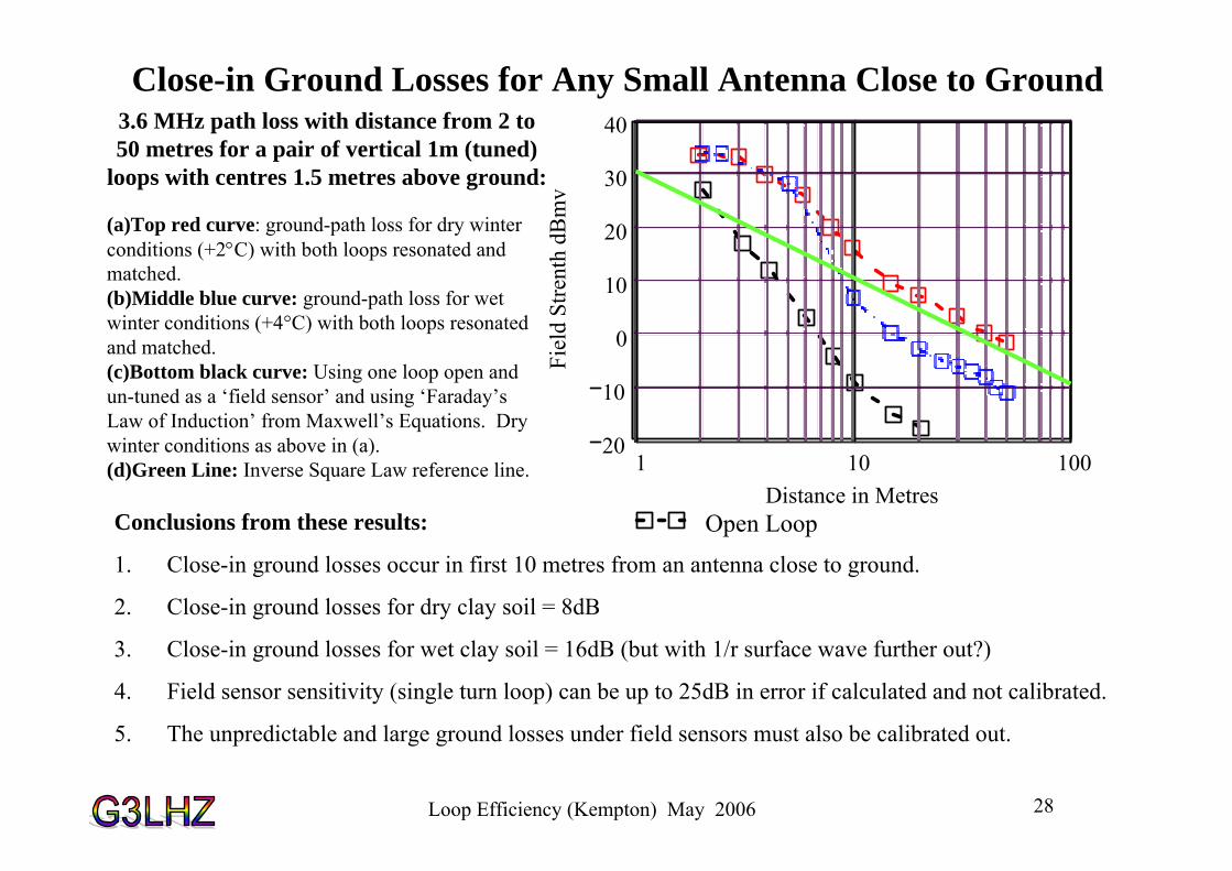
Close-in Ground Losses for Any Small Antenna Close to Ground3.6 MHz path loss with distance from 2 to 50 metres for a pair of vertical 1m (tuned)
loops with centres 1.5 metres above ground:
(a)Top red curve: ground-path loss for dry winter conditions (+2°C) with both loops resonated and matched. (b)Middle blue curve: ground-path loss for wet winter conditions (+4°C) with both loops resonated and matched.(c)Bottom black curve: Using one loop open and un-tuned as a ‘field sensor’ and using ‘Faraday’s Law of Induction’ from Maxwell’s Equations. Dry winter conditions as above in (a). (d)Green Line: Inverse Square Law reference line. 1 10 100
20
10
0
10
20
30
40
Open LoopDistance in Metres
Fiel
d St
rent
h dB
mv
Conclusions from these results:
1. Close-in ground losses occur in first 10 metres from an antenna close to ground.
2. Close-in ground losses for dry clay soil = 8dB
3. Close-in ground losses for wet clay soil = 16dB (but with 1/r surface wave further out?)
4. Field sensor sensitivity (single turn loop) can be up to 25dB in error if calculated and not calibrated.
5. The unpredictable and large ground losses under field sensors must also be calibrated out.
Loop Efficiency (Kempton) May 2006 29
Conclusions• Small Loops are 80 to 95% efficient for copper tube >10mm (with any feed type).• Losses decrease inversely proportional to tube diameter. Double the diameter means
half the loss. This is irrespective of loop size. • High power loops need to be >90% efficient – to prevent self-destruction by self-
heating.• Two loops in parallel will nearly double the bandwidth and at least double the power
handling before flashover.• The novel (G3LHZ) diagonal fed square or circular loops give 3 to 4 times the
bandwidth and power handling before capacitor flashover.• The novel (G3LHZ) ‘mini-midi loop’ reduces Q from about 300 typically down to
about 30 to 40. A 3% bandwidth is achievable (and double this with an ATU).• A 500 watt 1.7m top-band loop has been made (with single centre line tuning).• A 1m square loop has been made which can handle 750watts on 80m.• The ground losses under a loop limit its performance. At 15m height these become
minimal. • The patterns (and polarisation) of the centre-line and diagonal loops are unusual and
are being investigated.