LABORATORY MANUAL - Atria
66
LABORATORY MANUAL 18MEL57 FLUID MECHANICS AND MACHINES LAB 2019-2020 DEPARTMENT OF MECHANICAL ENGINEERING ATRIA INSTITUTE OF TECHNOLOGY Adjacent to Bangalore Baptist Hospital Hebbal, Bengaluru-560024
Transcript of LABORATORY MANUAL - Atria
LABORATORY MANUAL
18MEL57 FLUID MECHANICS AND MACHINES LAB
2019-2020
DEPARTMENT OF MECHANICAL ENGINEERING
ATRIA INSTITUTE OF TECHNOLOGY
Adjacent to Bangalore Baptist Hospital
Hebbal, Bengaluru-560024

Department of Mechanical Engineering
Vision
To be a center of excellence in Mechanical Engineering education and interdisciplinary
research to confront real world societal problems with professional ethics.
Mission
1. To push the frontiers of pedagogy amongst the students and develop new paradigms in
research.
2. To develop products, processes, and technologies for the benefit of society in
collaboration with industry and commerce.
3. To mould the young minds and build a comprehensive personality by nurturing
strong professionals with human ethics through interaction with faculty, alumni, and
experts from academia/industry.

PREFACE
In most of the engineering institutions, the laboratory course forms an integral form of the basic course in
Fluid Mechanics at undergraduate level. The experiments to be performed in a laboratory should ideally be
designed in such a way as to reinforce the understanding of the basic principles as well as help the students
to visualize the various phenomenon encountered in different applications.. The fluid mechanics lab
contributes to educate the undergraduate students of 5th semester B.E, VTU Belagavi in the field of
Mechanical Engineering.
The objective of this laboratory is to reinforce and enhance your understanding of the fundamentals of Fluid
mechanics and Hydraulic machines. The experiments here are designed to demonstrate the applications of
the basic fluid mechanics principles and to provide a more intuitive and physical understanding of the
theory. The main objective is to introduce a variety of classical experimental and diagnostic techniques, and
the principles behind these techniques. This laboratory exercise also provides practice in making engineering
judgments, estimates and
Assessing the reliability of your measurements, skills which are very important in all engineering
disciplines.
I acknowledge Dr.Ram, Head of the Department for his valuable guidance and suggestions as per Revised
Blooms Taxonomy in preparing the lab manual.
Mrs. Geetha Chavan
Mr. Deepnarayan Singh
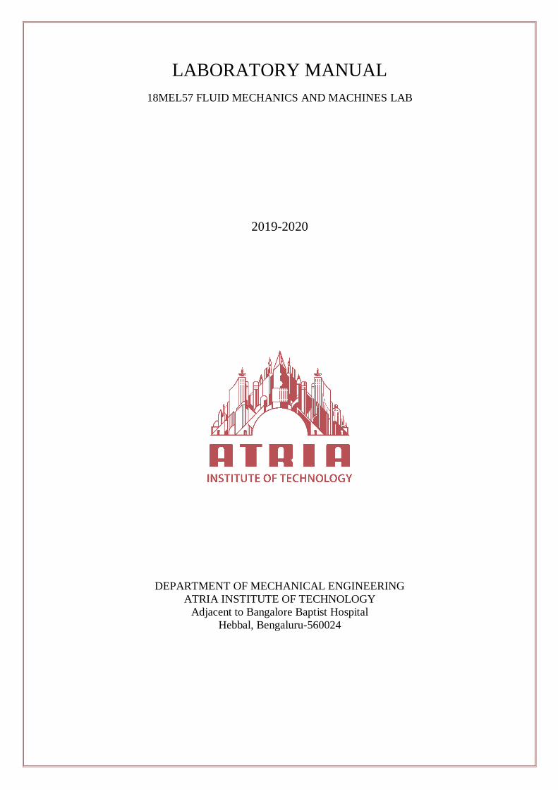
KAPLAN TURBINE
The Kaplan turbine is a propeller-type water
turbine which has adjustable blades. It was
developed in 1913 by Austrian professor Viktor
Kaplan, who combined automatically adjusted
propeller blades with automatically
adjusted wicket gates to achieve efficiency over a
wide range of flow and water level.
The Kaplan turbine was an evolution of
the Francis turbine. Its invention allowed efficient
power production in low-head applications which
was not possible with Francis turbines.
FRANCIS TURBINE
The Francis turbine is a type of water turbine. It
is an inward-flow reaction turbine that
combines radial and axial flow concepts. Francis
turbines are the most common water turbine in use
today, and can achieve over 95% efficiency.
The process of arriving at the modern Francis
runner design took from 1848 to approximately
1920. It became known as the Francis turbine
around 1920, being named after British-American
engineer James B. Francis who in 1848 created a
new turbine design.
Francis turbines are primarily used for electrical
power production. The power output of
the electric generators generally ranges from just a
few kilowatts up to 1000 MW.

FLUID MECHANICS AND MACHINERY LABORATORY
Syllabus
Subject Code: 18MEL57 IA Marks: 20
No. of Lecturer Hrs/ Week: 01 Exam Hours: 03
No. of Practical Hrs/ Week: 02 Exam Marks: 80
PART - A
1. Determination of coefficient of friction of flow in a pipe.
2. Determination of minor losses in flow through pipes.
3. Determination of force developed by impact of jets on vanes.
4. Calibration of flow measuring devices
a. Orifice Plate meter
b. Nozzle
c. Venturimeter
d. V-notch
PART - B
5. Performance testing of Turbines
a. Pelton wheel
b. Francis Turbine
c. Kaplan Turbines
6. Performance testing of Pumps
a. Single stage / Multi stage centrifugal pumps
b. Reciprocating pump
7. Performance test of a two stage Reciprocating Air Compressor
8. Performance test on an Air Blower
Scheme for Examination:
One Question from Part A - 25 Marks (10 Writeup+15)
One Question from Part B - 40 Marks (15 Writeup+25)
Viva-Voce - 15 Marks
Total 80 Marks
CONTENTS
Sl
No EXPERIMENTS Page No
1 PIPE FRICTION AND PIPE FITTING APPARATUS
2 MINOR LOSSES IN PIPE FITTING APPARATUS
3 IMPACT OF JET APPARATUS
4 FLOW MEASURMENT BY VENTURI METER , ORIFICEMETER
& ROTOMETER
5 FLOW– OVER NOTCHES
6 FLOW– OVER NOTCHES
7 PELTON WHEEL TURBINE
8 FRANCIS TURBINE
9 CENTRIFUGAL PUMP ( single stage)
10 RECIPROCATING PUMP
11 TWO STAGE AIR COMPRESSOR
12 AIR BLOWER TEST RIG:-
13 KAPLAN TURBINE
VIVA QUESTIONS

Fluid Mechanics and Machinery Laboratory 18MEL57
Department of Mechanical Engineering,
Atria Institute of Technology
Page 7
PART-A
EXPERIMENT-No. 1
PIPE FRICTION AND PIPE FITTING APPARATUS.
AIM:- To determine coefficient of friction for pipes& head lost in pipe friction.
APPARATUS:-Set up of pipe friction apparatus, stop watch.
THEORY:
The fluid flow through a pipe line is characterized by energy losses. Energy loss is
characterized as major energy loss and minor energy losses. Major energy loss is due to the
friction and minor energy loss is due to the change in pipe line geometry. Energy loss due to
friction is much more than the minor losses so that minor losses can be neglected. While the
nature of flow depends upon the flow Reynolds’s number, the frictional resistance offered to
the flow of fluid depends essentially on the roughness of the surface of the conduct carrying
the flow. in laminar flow the frictional resistance is due to viscous resistance of the fluid to
flow. in turbulent it is due to the resistance offered by viscosity of fluid and surface roughness
of the conduct. The frictional resistance varies with
1. with the degree of roughness of surface with which fluid comes in contact.
2. with the extent of area of surface coming in contact with the fluid
3. Directly as the velocity in laminar flows and as the square of velocity in laminar flows
And as the square of velocity in turbulent flow
4. Directly as the density of fluid
5. Inversely as the velocity of fluid
SPECIFICATIONS:-
1. Supply Tank Volume – 1270 x 375 x 400 mm. 2. Two pipes –
a) Diameter of pipe - 22 mm.
b) Diameter of pipe - 17 mm.
3. Length of pipe L = 1000 mm = 1 m
4. Area of measuring tank A = (0.375 x 0.33) m2
PROCEDURE:-
1. Before starting flow through pipes the initials manometer reading is taken. 2. Then the fluid is allowed to flow through pipes.
3. Then the manometer reading on the pipe is taken down.
4. Take the time required for 100 mm rise in water level in measuring tank.
5. Above procedure is repeated for different discharges.
6. Take at least 2 or 3 readings.

Fluid Mechanics and Machinery Laboratory 18MEL57
Department of Mechanical Engineering,
Atria Institute of Technology
Page 8
OBSERVATION TABLE:-
CALCULATIONS:-
1 Head lost in friction in m of water(hf) = ( h1+ h2/1000) x 13.6
1m of Hg = 13.6 m of water.
2 Velocity (v) in m/s.
V=Q/A
Where,
Q = discharge in m3/sec
Area of measuring tank x0.1
Q =
Time required (sec)
A = area of the pipe in m2.
3 Co-efficient of friction (f)
fxLxV2
hf =
2gd
hf x 2gd
f =
Lx V2
Where,
hf = head lost in friction in meters of water.
g = 9.81 m/sec2
d = Diameter of the pipe in meter.
L = length of the pipe in meter .
V = velocity of flow through pipe in m/sec
Sl/No Manometer reading Difference
H =H1
Difference H
in m of water
Time required
for 100 mm rise
in water level H1 cm H2 cm
1
2
3
4
5

Fluid Mechanics and Machinery Laboratory 18MEL57
Department of Mechanical Engineering,
Atria Institute of Technology
Page 9
RESULT TABLE:-
Sl/No Discharge m3/sec
Head lost in friction (hf) in m of water
Co efficient of Friction (f)
Average (f)
NOTE:- as frictional head loss is inversely proportional to diameter of the pipe, the head loss
in 22mm dia pipe is very less with compared to 17 mm dia pipe.
ANALYSIS OF RESULTS:
DISCUSSIONS:
CONCLUSION: The coefficient of friction for pipes & head lost in pipe friction is calculated
experimentally determined.
Fluid Mechanics and Machinery Laboratory 18MEL57
Department of Mechanical Engineering,
Atria Institute of Technology
Page 10
EXPERIMENT No.2
MINOR LOSSES IN PIPE FITTING APPARATUS.
AIM: - To determine different losses due to pipe fittings.
APPARATUS: - Set up of pipe fitting apparatus
THEORY:
In most of the pipe flow problems, the flow is steady and uniform, and the loss of head due to
friction is predominant. In addition to the loss of head due to friction, the loss of head is also
occurs whenever there is change in the diameter or direction, or there is any obstruction in the
flow. These losses are called form losses or minor losses. The form losses are usually small
and insignificant in long pipes but for pipes of small length, they are quit large compared to the
friction loss. In some small length pipes, they may be even more predominant than that due to
friction.
The set-up consists of a small diameter pipe which suddenly changes to a large diameter pipe.
After a certain a length, the large diameter reduces to a small diameter. The small diameter
pipe has a 900 bend. Suitable pressure tapping points are provided to measure the loss of head
with an inverted U-tube manometer. The loss of head can be determined by connecting the
manometer across the section where the changes occur in the flow. The pipe is connected to a
constant-head supply tank. The water is collected in measuring tank for the determination of
the discharge.
SPECIFICATION:-
1. Sump Tank = 1270x375x400mm
2. Measuring Tank = 375x330x400 mm
3. Dia. Of enlargement = 22mm
4. Dia of Contraction = 17mm
5. Dia of bend = 17mm
6. Dia. of Elbow = 17mm
7. Area of measuring tank = 375x330mm2
PROCEDURE:-
1. Start the motor.
2. Then the fluid is allowed to flow through pipe fittings like sudden enlargement,
contraction, bend, and elbow.
3. Take manometer difference for each pipe fittings.
4. Take the time required for 100 mm rise of water level in measuring tank.
5. Above procedure is repeated for different discharges.
6. Take at least 2 to 3 readings.

Fluid Mechanics and Machinery Laboratory 18MEL57
Department of Mechanical Engineering,
Atria Institute of Technology
Page 11
OBESERVATION TABLE:-
For sudden enlargement, contraction, bend & elbow
Sl/No. Manometer readings
H1 H2
Difference
(H2+H1)
Time required for 100mm rise in
water level (sec.)
CALCULATION:-
1) Heat lost in m of water
1m of Hg = (H1+H2/10000) x13.6
2) Velocity (V) in m/s
V = Q/A Where,
Q = Discharge in m3/s
A = Area of the pipe fittings in m2
Area of measuring tank x0.1
3) Q =
Time required (sec)
4) Head loss ( Contraction)
0.5 v2
h1 =
2g
5) Head loss ( Enlargement)
(v1-v 2 2)
h1 = 2g
6) Head loss ( Bend)
0.25 v2
h1 =
2g
7) Head loss (Elbow)
0.25 v2
Fluid Mechanics and Machinery Laboratory 18MEL57
Department of Mechanical Engineering,
Atria Institute of Technology
Page 12
h1 =
2g
ANALYSIS OF RESULTS:
DISCUSSIONS:
CONCLUSION: The coefficient of friction for pipes & head losses is calculated
experimentally determined.

Fluid Mechanics and Machinery Laboratory 18MEL57
Department of Mechanical Engineering,
Atria Institute of Technology
Page 13
EXPERIMENT No.3
IMPACT OF JET APPARATUS
AIM: - Determination of force developed by impact of jet on vanes.
APPARATUS: - Impact of jet apparatus , standard dead weights.
THEORY:
The study of impact of a jet of water is essential to understand the principle of an impulse
turbine such as Pelton Wheel Turbine. When high pressure water from a source such as a dam
flows through a nozzle in the form of a jet, the entire pressure energy of the water is converted
into kinetic energy at the nozzle. When this jet of water hits a vane positioned in front of it, the
vane deflects the jet and due to the change in the momentum of the water jet, a force is
imparted to the vane by the water.
EXPERIMENTAL SETUP:
The equipment consists of a high efficiency gun metal nozzle fitted to a 25 mm diameter pipe
supply line with a gate valve. Vertically above the nozzle, a gun metal vane is fitted to a
bracket of a differential lever which balances the upward force of the jet from the nozzle. The
lever is provided with an adjustable no load screw mechanism. The force due to the jet on the
lever is counter balanced by weights placed on a hanger. Different types of vanes can be fitted
to the bracket. The complete assembly is enclosed in framed structure housing with two leak
proof transparent sides for visual observation. The water deflected by the vane is collected in
the collecting tank of the hydraulic bench. For experimental purposes, two brass nozzles with
nozzle outlet diameters of 8mm and 10mm and two gunmetal vanes of the following shape are
provided.
1. Semi-circular vane (1800 Angle of deflection)
2. Horizontal flat vane (900.angle of deflection)
SPECIFICATIONS :- Supply tank = 600 x 600 x500mm.
Measuring tank = 400 x 260 x375mm
Diameter of nozzle = 8 mm Density of water = 1000 kg/m3
Area of measuring tank = (0.4x0.26) m 2
Angle at which the plate is inclined Ө = 600 (for inclined plate)
PROCEDURE:-
1 First balance the lever mechanism to zero.
2 Start the motor.
3 Allow some time to flow the water on the jet.
4 As water coming from the jet, impacts on the vanes, the lever mechanism
goes to the up word direction.
5 Again balance the lever mechanism by loading weights on the other side of
Fluid Mechanics and Machinery Laboratory 18MEL57
Department of Mechanical Engineering,
Atria Institute of Technology
Page 14
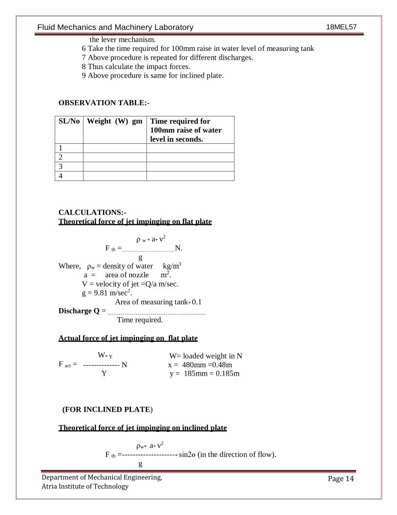
the lever mechanism.
6 Take the time required for 100mm raise in water level of measuring tank
7 Above procedure is repeated for different discharges.
8 Thus calculate the impact forces.
9 Above procedure is same for inclined plate.
OBSERVATION TABLE:-
SL/No Weight (W) gm Time required for
100mm raise of water
level in seconds.
1
2
3
4
CALCULATIONS:-
Theoretical force of jet impinging on flat plate
ρ w * a* v2
F th = N.
g
Where, ρw = density of water kg/m3
a = area of nozzle m2.
V = velocity of jet =Q/a m/sec.
g = 9.81 m/sec2.
Area of measuring tank* 0.1
Discharge Q =
Time required.
Actual force of jet impinging on flat plate
W* Y W= loaded weight in N F act = -------------- N x = 480mm =0.48m
Y y = 185mm = 0.185m
(FOR INCLINED PLATE)
Theoretical force of jet impinging on inclined plate
ρw* a* v2
F th =-------------------- * sin2ө (in the direction of flow).
g

Fluid Mechanics and Machinery Laboratory 18MEL57
Department of Mechanical Engineering,
Atria Institute of Technology
Page 15
ρw* a* v2
F th = ------------------- * sin2ө (in the direction normal to flow).
2 g
Actual force of jet impinging on inclined plate
W x W= loaded weight in N
F act = -------------- N x = 480mm =0.48m
y y = 185mm = 0.185mρ
k= Fact
Fthe
RESULT TABLE
SL/No Weight (gm)
Discharge m3/sec
Velocity m/s
F th
N
F act
N
ANALYSIS OF RESULTS:
DISCUSSIONS:
CONCLUSION: Theoretical force and actual force of jet impinging on inclined plate is
determined.
Fluid Mechanics and Machinery Laboratory 18MEL57
Department of Mechanical Engineering,
Atria Institute of Technology
Page 16
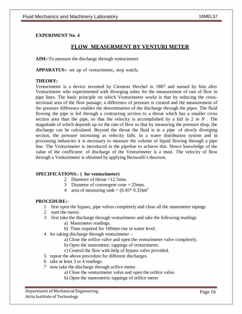
EXPERIMENT No. 4
FLOW MEASURMENT BY VENTURI METER
AIM:-To measure the discharge through venturimeter
APPARATUS:- set up of venturimeter, stop watch.
THEORY:
Venturimeter is a device invented by Ciemens Herchel in 1887 and named by him after Venturimeter who experimented with diverging tubes for the measurement of rate of flow in
pipe lines. The basic principle on which Venturimeter works is that by reducing the cross-
sectional area of the flow passage, a difference of pressure is created and the measurement of
the pressure difference enables the determination of the discharge through the pipes. The fluid
flowing the pipe is led through a contracting section to a throat which has a smaller cross
section area than the pipe, so that the velocity is accomplished by a fall in 2 m N . The
magnitude of which depends up on the rate of flow so that by measuring the pressure drop, the
discharge can be calculated. Beyond the throat the fluid is in a pipe of slowly diverging
section, the pressure increasing as velocity falls. In a water distribution system and in
processing industries it is necessary to measure the volume of liquid flowing through a pipe
line. The Venturimeter is introduced in the pipeline to achieve this. Hence knowledge of the
value of the coefficient of discharge of the Venturimeter is a must. The velocity of flow
through a Venturimeter is obtained by applying Bernoulli’s theorem.
SPECIFICATIONS:- ( for venturimeter)
2 Diameter of throat =12.5mm. 3 Diameter of convergent cone = 25mm.
4 area of measuring tank = (0.45* 0.33)m2
PROCEDURE:-
1 first open the bypass, pipe valves completely and close all the manometer tapings
2 start the motor.
3 first take the discharge through venturimeter and take the following readings
a) Manometer readings.
b) Time required for 100mm rise in water level.
4 for taking discharge through venturimeter –
a) Close the orifice valve and open the venturimeter valve completely.
b) Open the manometer, tappings of venturimeter.
c) Control the flow with help of bypass valve provided.
5 repeat the above procedure for different discharges.
6 take at least 3 or 4 readings.
7 now take the discharge through orifice meter.
a) Close the venturimeter valve and open the orifice valve.
b) Open the manometric tappings of orifice meter

Fluid Mechanics and Machinery Laboratory 18MEL57
Department of Mechanical Engineering,
Atria Institute of Technology
Page 17
2
c) Control the flow with the help of by-pass valve provided.
8 take the following readings.
a) Manometric readings.
b) time required for 100mm rise in water level.
9 repeat the above procedure for different discharges .
10 take at least 3or 4 readings.
OBSERVATION TABLE :-( for venturimeter)
Sl/No H1 cm
H2 cm
Diff(H) m of water
Time required for 100 mm
rise in water level
1
2
3
4
5
CALCULATIONS :- (For venturimeter)
1 theoretical discharge :- a1* a2
Qth = -------------------------------x√2gH = C√H √a1
2 -a 2
Where,
a1 = area of venturimeter at convergent cone in m2 (4.90x10 -4)
a2 = area of venturimeter at throat in m2 (1.22x 10⁻⁴).
H = head in meter ( h1+h2/1000)x13.6
C = 5.61x 10 -4
2 Actual discharge:-
Area of measuring tank x0.1
Q act =
Time required (sec)
3 1m of Hg = 13.6 m of water. Q act
4 Cd =
Q th

Fluid Mechanics and Machinery Laboratory 18MEL57
Department of Mechanical Engineering,
Atria Institute of Technology
Page 18
GRAPH: Q act V/S manometer difference
RESULT TABLE:- (for venturimeter)
Sl/No Head (H) m of water
Q th m3/sec
Q act m3/sec
C d Average C d
ANALYSIS OF RESULTS:
DISCUSSIONS:
Fluid Mechanics and Machinery Laboratory 18MEL57
Department of Mechanical Engineering,
Atria Institute of Technology
Page 19
CONCLUSION: The co efficient of discharge through venturimeter is determined
EXPERIMENT No. 5
FLOW MEASURMENT BY ORIFICEMETER AIM:-To measure the discharge through orifice meter.
APPARATUS:- set up of orifice meter, stop watch.
THEORY:
Orifice meter is used to measure the discharge in any closed surface. Orifice meter works on
the principle that by reducing the cross section area of the flow passage, a pressure difference
between the two sections is developed and this difference enables the determination of the
discharge through the pipe. In a water distribution system and in processing industries it is
necessary to measure the volume of liquid flowing through a pipe line. The orifice meter is
introduced in the pipeline to achieve this. Hence knowledge of the value of the coefficient of
discharge of the orifice meter is a must. Orifice meter consists of a flat circular plate with a
circular hole called orifice, which is concentric with the pipe axis pressure tapings are
connected to pipe wall on the both sides of the plate. So that the difference in the fluid pressure
on both sides of the orifice plate are measured.
SPECIFICATIONS
(For orifice meter,)
1 Diameter of orifice = 13mm. 2 area of measuring tank = (0.45* 0.33)m2
PROCEDURE:-
1 first open the bypass, pipe valves completely and close all the manometer tapings 2 start the motor.
3 first take the discharge through venturimeter and take the following readings
a) Manometer readings.
b) Time required for 100mm rise in water level.
4 for taking discharge through venturimeter –
a) Close the orifice valve and open the venturimeter valve completely.
b) Open the manometer, tappings of venture meter.
c) Control the flow with help of bypass valve provided.
5 repeat the above procedure for different discharges.
6 take at least 3 or 4 readings.
7 now take the discharge through orifice meter.
a) Close the venturimeter valve and open the orifice valve.
b) Open the manometric tappings of orifice meter
c) Control the flow with the help of bypass valve provided.
8 take the following readings.
a) Manometric readings.
b) Time required for 100mm rise in water level.
9 repeat the above procedure for different discharges.
10 take at least 3or 4 readings.
Fluid Mechanics and Machinery Laboratory 18MEL57
Department of Mechanical Engineering,
Atria Institute of Technology
Page 20
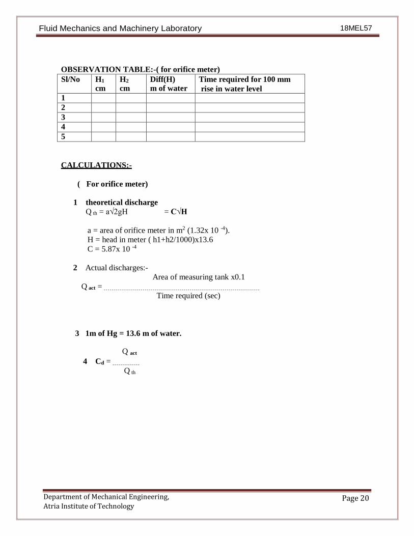
OBSERVATION TABLE:-( for orifice meter)
Sl/No H1 cm
H2 cm
Diff(H) m of water
Time required for 100 mm
rise in water level
1
2
3
4
5
CALCULATIONS:-
(
1
For orifice meter)
theoretical discharge
Q th = a√2gH = C√H
a = area of orifice meter in m2 (1.32x 10 -4).
H = head in meter ( h1+h2/1000)x13.6
C = 5.87x 10 -4
2 Actual discharges:-
Area of measuring tank x0.1
Q act =
Time required (sec)
3 1m of Hg = 13.6 m of water.
Q act
4 Cd =
Q th
Fluid Mechanics and Machinery Laboratory 18MEL57
Department of Mechanical Engineering,
Atria Institute of Technology
Page 21
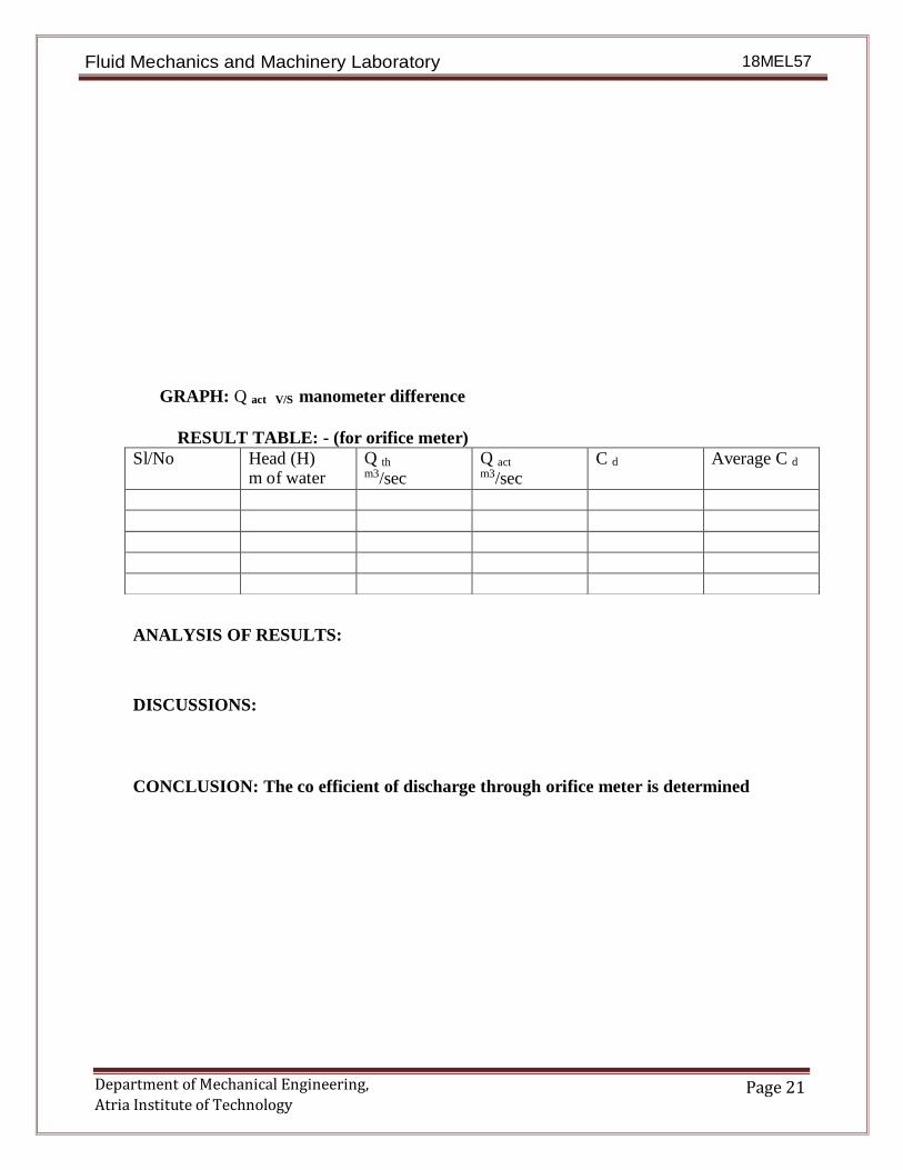
GRAPH: Q act V/S manometer difference
RESULT TABLE: - (for orifice meter)
ANALYSIS OF RESULTS:
DISCUSSIONS:
CONCLUSION: The co efficient of discharge through orifice meter is determined
Sl/No Head (H) m of water
Q th m3/sec
Q act m3/sec
C d Average C d
Fluid Mechanics and Machinery Laboratory 18MEL57
Department of Mechanical Engineering,
Atria Institute of Technology
Page 22
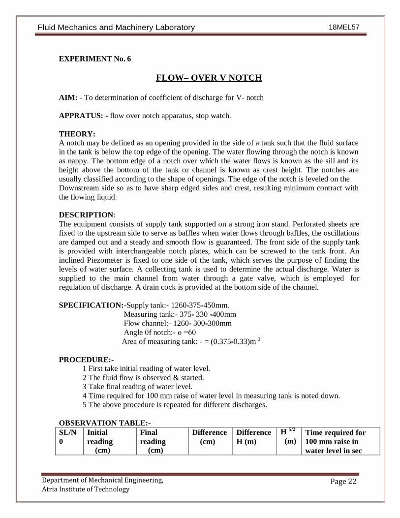
EXPERIMENT No. 6
FLOW– OVER V NOTCH
AIM: - To determination of coefficient of discharge for V- notch
APPRATUS: - flow over notch apparatus, stop watch.
THEORY:
A notch may be defined as an opening provided in the side of a tank such that the fluid surface
in the tank is below the top edge of the opening. The water flowing through the notch is known
as nappy. The bottom edge of a notch over which the water flows is known as the sill and its
height above the bottom of the tank or channel is known as crest height. The notches are
usually classified according to the shape of openings. The edge of the notch is leveled on the
Downstream side so as to have sharp edged sides and crest, resulting minimum contract with
the flowing liquid.
DESCRIPTION:
The equipment consists of supply tank supported on a strong iron stand. Perforated sheets are
fixed to the upstream side to serve as baffles when water flows through baffles, the oscillations
are damped out and a steady and smooth flow is guaranteed. The front side of the supply tank
is provided with interchangeable notch plates, which can be screwed to the tank front. An
inclined Piezometer is fixed to one side of the tank, which serves the purpose of finding the
levels of water surface. A collecting tank is used to determine the actual discharge. Water is
supplied to the main channel from water through a gate valve, which is employed for
regulation of discharge. A drain cock is provided at the bottom side of the channel.
SPECIFICATION:-Supply tank:- 1260*375*450mm.
Measuring tank:- 375* 330 *400mm
Flow channel:- 1260* 300*300mm
Angle 0f notch:- ө =60
Area of measuring tank: - = (0.375*0.33)m 2
PROCEDURE:-
1 First take initial reading of water level.
2 The fluid flow is observed & started.
3 Take final reading of water level.
4 Time required for 100 mm raise of water level in measuring tank is noted down.
5 The above procedure is repeated for different discharges.
OBSERVATION TABLE:-
SL/N
0
Initial
reading (cm)
Final
reading (cm)
Difference
(cm)
Difference
H (m)
H 5/2
(m) Time required for
100 mm raise in
water level in sec
Fluid Mechanics and Machinery Laboratory 18MEL57
Department of Mechanical Engineering,
Atria Institute of Technology
Page 23
1
2
3
CALCULATIONS:-
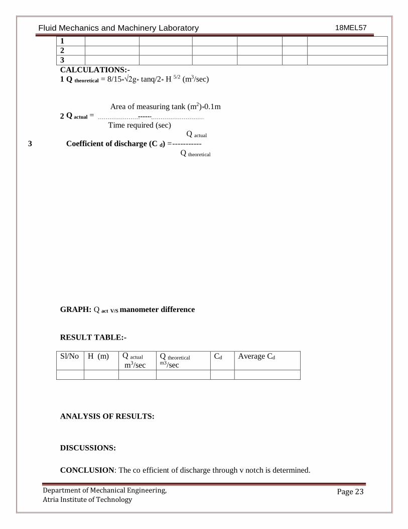
1 Q theoretical = 8/15*√2g* tanq/2* H 5/2 (m3/sec)
Area of measuring tank (m2)*0.1m
2 Q actual = Time required (sec)
Q actual
3 Coefficient of discharge (C d) = -----------
Q theoretical
GRAPH: Q act V/S manometer difference
RESULT TABLE:-
Sl/No H (m) Q actual
m3/sec
Q theoretical m3/sec
Cd Average Cd
ANALYSIS OF RESULTS:
DISCUSSIONS:
CONCLUSION: The co efficient of discharge through v notch is determined.

Fluid Mechanics and Machinery Laboratory 18MEL57
Department of Mechanical Engineering,
Atria Institute of Technology
Page 24
PATR-B
EXPERIMENT No.7
PELTON WHEEL TURBINE
AIM:- Performance testing of pelton wheel turbine
APPARATUES: - pelton wheel turbine, tachometer & stop watch.
DESCRIPTION:
Pelton wheel is an impulse turbine which is used to utilize high heads for generation of
electricity. It consists of a runner mounted on a shaft. To this a brake drum is attached to apply
brakes over the speed of the turbine. A casing is fixed over the runner. All the available head is
converted into velocity energy by means of spear and nozzle arrangement. The spear can be
positioned in 8 places that is, 1/8, 2/8, 3/8, 4/8, 5/8 6/8, 7/8 and 8/8 of nozzle opening. The jet
of water then strikes the buckets of the Pelton wheel runner. The buckets are in shape of double
cups joined at middle portion. The jet strikes the knife edge of the buckets with least resistance
and shock. The jet is deflected through more than 160o to 170o. While the specific speed of
Pelton wheel changes from 10 to 100 passing along the buckets, the velocity of water is
reduced and hence the impulsive force is supplied to the cups which in turn are moved and
hence the shaft is rotated. The supply of water is arranged by means of centrifugal pump. The
speed of turbine is measured with tachometer.
SPECIFICATIONS:-
Speed of the turbine = 2880 rpm
Diameter of the drum =265mm
Diameter of the rope = 15 mm.
Effective diameter (D) = 0.280m. (Re-0.14m)
PROCEDURE:- ( for constant speed)
1 Keep the gate valve in the pipe line open and start the motor.
2 gradually close the gate valve &apply certain load.
3 gradually close the gate valve &bring the speed of runner to rotated valve.
4 note the following readings.
A) pressure gauges reading.
b) Spring balance reading.
c) Speed of the runner.
5 take at least 6-7 readings, keeping speed of the turbine constant.
6 tabulate the readings neatly.
(For constant head)
1 Keep the gate valve in the pipe line open and start the motor.
Fluid Mechanics and Machinery Laboratory 18MEL57
Department of Mechanical Engineering,
Atria Institute of Technology
Page 25
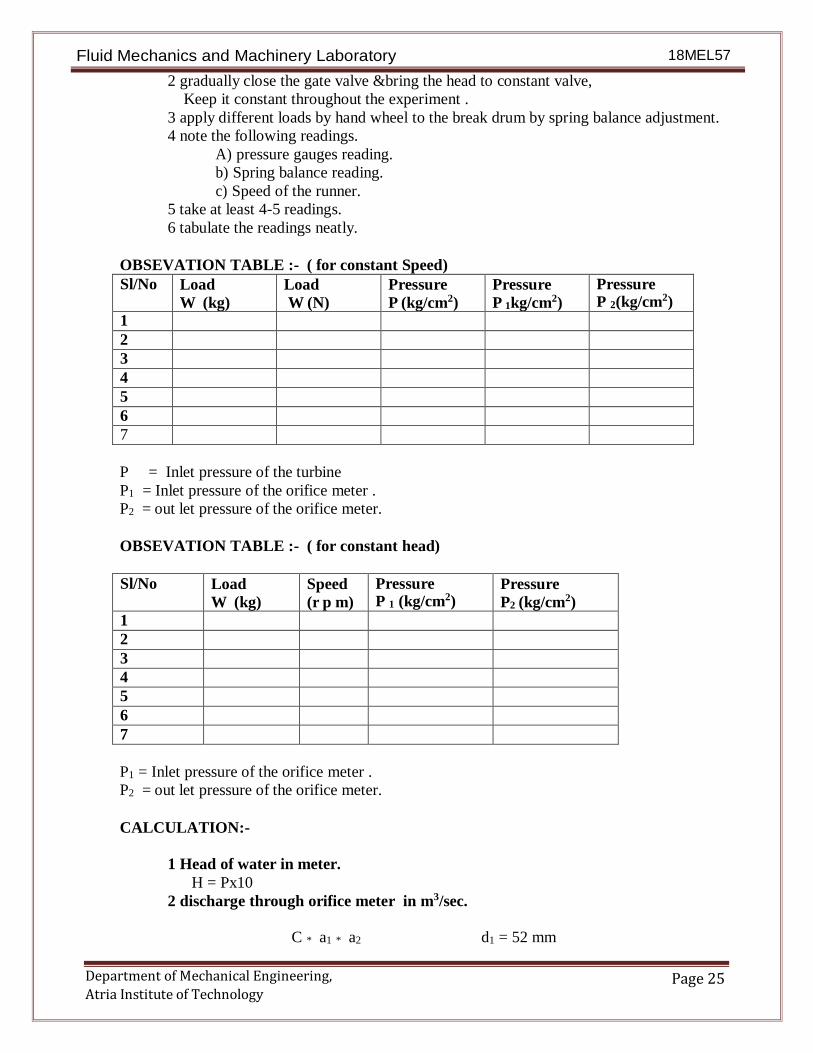
2 gradually close the gate valve &bring the head to constant valve,
Keep it constant throughout the experiment .
3 apply different loads by hand wheel to the break drum by spring balance adjustment.
4 note the following readings.
A) pressure gauges reading.
b) Spring balance reading.
c) Speed of the runner.
5 take at least 4-5 readings.
6 tabulate the readings neatly.
OBSEVATION TABLE :- ( for constant Speed)
Sl/No Load
W (kg)
Load
W (N)
Pressure
P (kg/cm2)
Pressure
P 1kg/cm2)
Pressure P 2(kg/cm2)
1
2
3
4
5
6
7
P = Inlet pressure of the turbine
P1 = Inlet pressure of the orifice meter .
P2 = out let pressure of the orifice meter.
OBSEVATION TABLE :- ( for constant head)
Sl/No Load
W (kg)
Speed
(r p m)
Pressure P 1 (kg/cm2)
Pressure
P2 (kg/cm2)
1
2
3
4
5
6
7
P1 = Inlet pressure of the orifice meter .
P2 = out let pressure of the orifice meter.
CALCULATION:-
1 Head of water in meter.
H = Px10
2 discharge through orifice meter in m3/sec.
C * a1 * a2 d1 = 52 mm
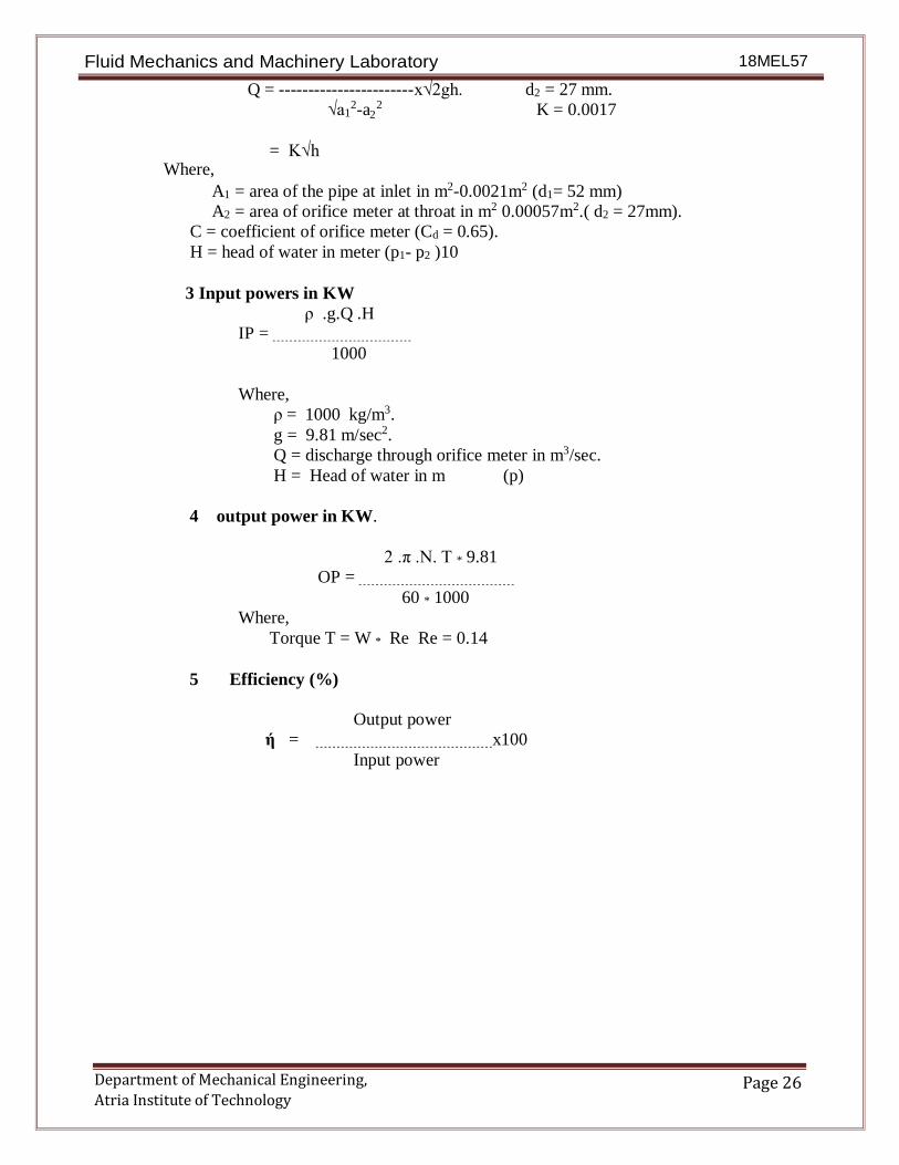
Fluid Mechanics and Machinery Laboratory 18MEL57
Department of Mechanical Engineering,
Atria Institute of Technology
Page 26
2
Q = -----------------------x√2gh. d2 = 27 mm.
√a12-a 2 K = 0.0017
= K√h Where,
A1 = area of the pipe at inlet in m2-0.0021m2 (d1= 52 mm)
A2 = area of orifice meter at throat in m2 0.00057m2.( d2 = 27mm).
C = coefficient of orifice meter (Cd = 0.65).
H = head of water in meter (p1- p2 )10
3 Input powers in KW
ρ .g.Q .H IP =
1000
Where,
ρ = 1000 kg/m3.
g = 9.81 m/sec2.
Q = discharge through orifice meter in m3/sec.
H = Head of water in m (p)
4 output power in KW.
Where,
2 .π .N. T * 9.81
OP =
60 * 1000
Torque T = W * Re Re = 0.14
5 Efficiency (%)
Output power
ή = x100
Input power
Fluid Mechanics and Machinery Laboratory 18MEL57
Department of Mechanical Engineering,
Atria Institute of Technology
Page 27
\
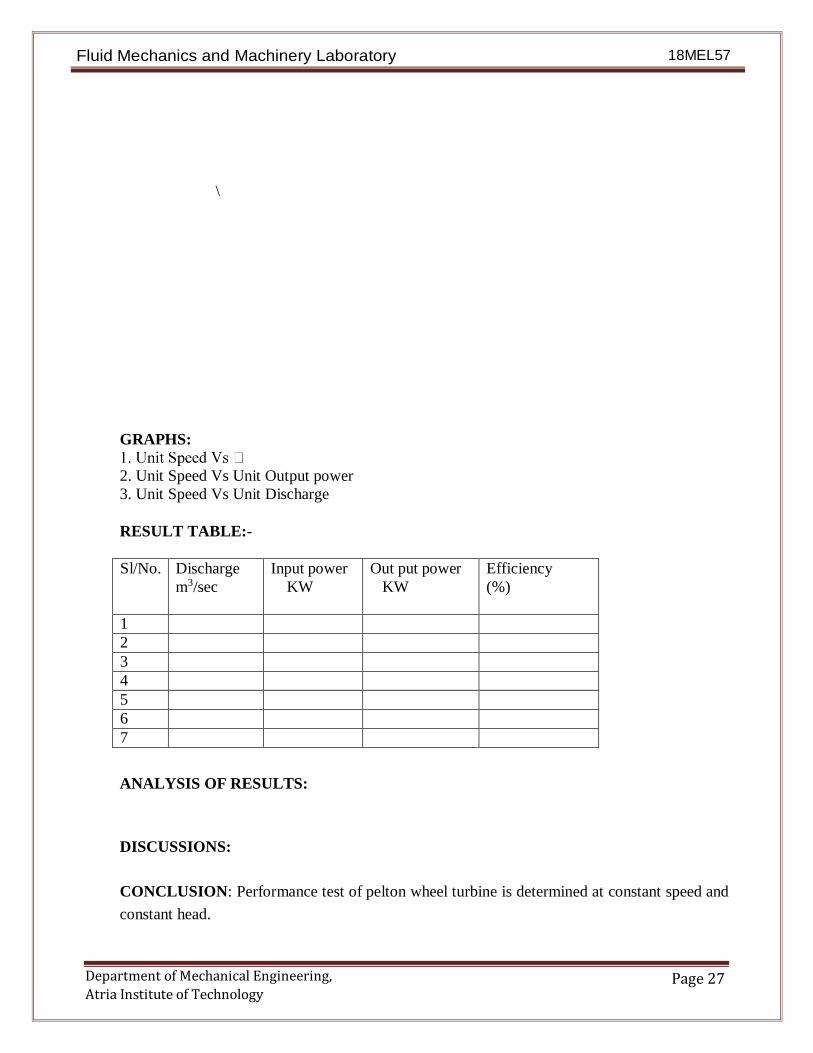
GRAPHS:
2. Unit Speed Vs Unit Output power
3. Unit Speed Vs Unit Discharge
RESULT TABLE:-
Sl/No. Discharge
m3/sec
Input power
KW
Out put power
KW
Efficiency
(%)
1
2
3
4
5
6
7
ANALYSIS OF RESULTS:
DISCUSSIONS:
CONCLUSION: Performance test of pelton wheel turbine is determined at constant speed and
constant head.
Fluid Mechanics and Machinery Laboratory 18MEL57
Department of Mechanical Engineering,
Atria Institute of Technology
Page 28
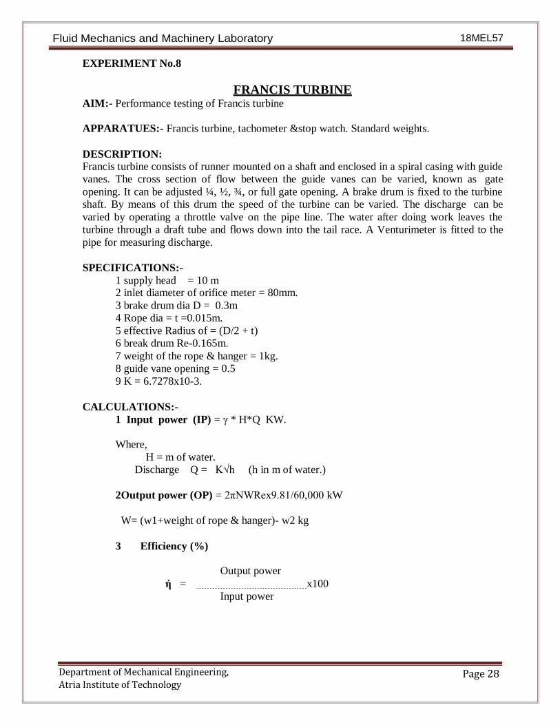
EXPERIMENT No.8
FRANCIS TURBINE AIM:- Performance testing of Francis turbine
APPARATUES:- Francis turbine, tachometer &stop watch. Standard weights.
DESCRIPTION:
Francis turbine consists of runner mounted on a shaft and enclosed in a spiral casing with guide
vanes. The cross section of flow between the guide vanes can be varied, known as gate
opening. It can be adjusted ¼, ½, ¾, or full gate opening. A brake drum is fixed to the turbine
shaft. By means of this drum the speed of the turbine can be varied. The discharge can be
varied by operating a throttle valve on the pipe line. The water after doing work leaves the
turbine through a draft tube and flows down into the tail race. A Venturimeter is fitted to the
pipe for measuring discharge.
SPECIFICATIONS:-
1 supply head = 10 m 2 inlet diameter of orifice meter = 80mm.
3 brake drum dia D = 0.3m
4 Rope dia = t =0.015m.
5 effective Radius of = (D/2 + t)
6 break drum Re-0.165m.
7 weight of the rope & hanger = 1kg.
8 guide vane opening = 0.5
9 K = 6.7278x10⁻³.
CALCULATIONS:-
1 Input power (IP) = γ * H*Q KW.
Where,
H = m of water.
Discharge Q = K√h (h in m of water.)
2Output power (OP) = 2πNWRex9.81/60,000 kW
W= (w1+weight of rope & hanger)- w2 kg
3 Efficiency (%)
Output power
ή = x100
Input power
Fluid Mechanics and Machinery Laboratory 18MEL57
Department of Mechanical Engineering,
Atria Institute of Technology
Page 29
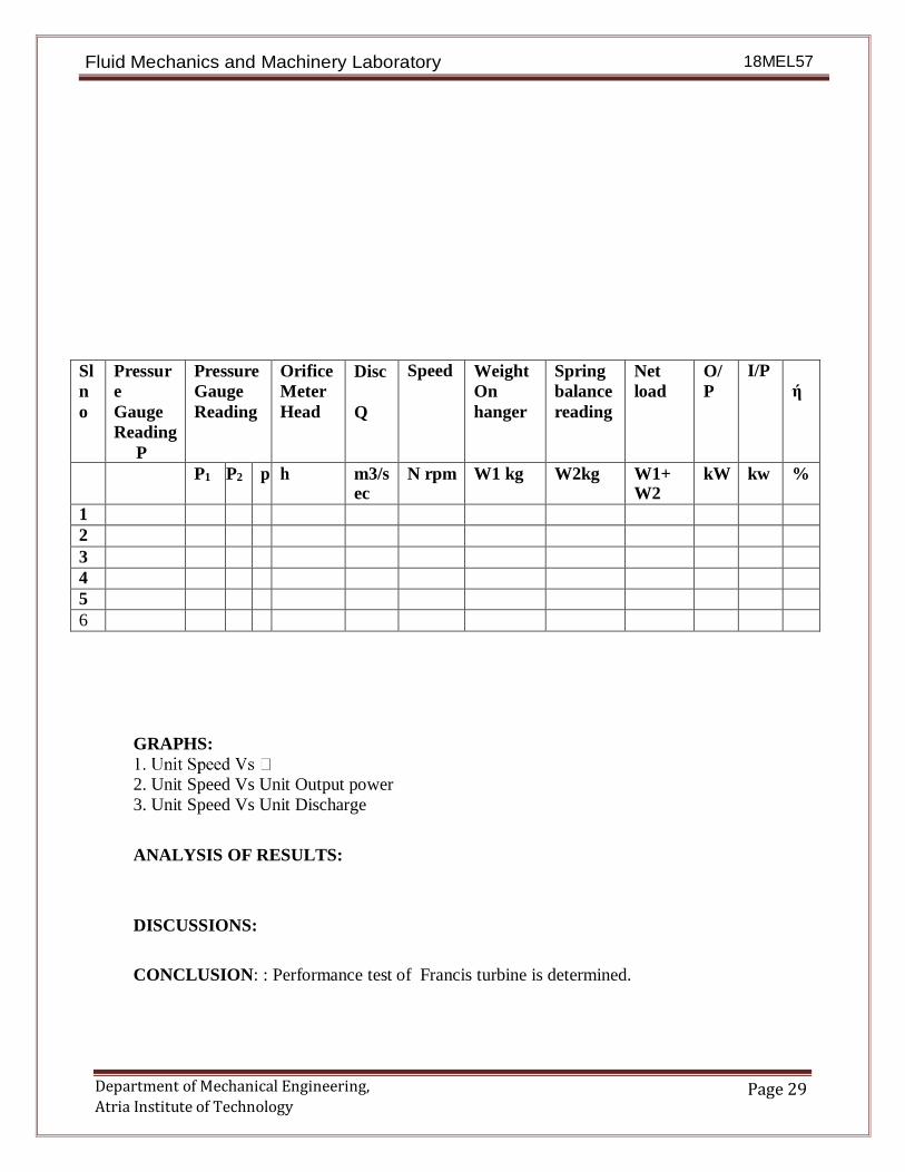
Sl
n
o
Pressur
e
Gauge
Reading
P
Pressure
Gauge
Reading
Orifice
Meter
Head
Disc
Q
Speed Weight
On
hanger
Spring
balance
reading
Net
load
O/
P
I/P
ή
P1 P2 p h m3/s ec
N rpm W1 kg W2kg W1+ W2
kW kw %
1
2
3
4
5
6
GRAPHS:
2. Unit Speed Vs Unit Output power
3. Unit Speed Vs Unit Discharge
ANALYSIS OF RESULTS:
DISCUSSIONS:
CONCLUSION: : Performance test of Francis turbine is determined.

Fluid Mechanics and Machinery Laboratory 18MEL57
Department of Mechanical Engineering,
Atria Institute of Technology
Page 30
EXPERIMENT No.9
CENTRIFUGAL PUMP (single stage)
AIM: - To determine the performance of single stage centrifugal pump.
APPARATUS: - single stage centrifugal pump, stop watch, Tachometer
THEORY:
In general a pump may be defined as a mechanical device which, when interposed in a pipe
line, converts the mechanical energy supplied to it from some external source into hydraulic
energy, thus resulting in the flow of liquid from lower potential to higher potential.
The centrifugal pump which is of present concern falls into the category of Rotodynamic
pumps. In this pump, the liquid is made to rotate in a closed chamber (volute casing) thus
creating a centrifugal action which gradually built up the pressure gradient towards outlet, thus
resulting in the continuous flow. These pumps compared to reciprocating pumps are simple in
construction, more suitable for handling viscous, turbid (muddy) liquids, can be directly
coupled to high speed electric motors (without any speed reduction ) & easy to maintain. But,
their hydraulic heads at low flow rates is limited, and hence not suitable for very high heads
compared to reciprocating pump of same capacity. But, still in most cases, this is the only type
of pump which is being widely used for agricultural applications because of its practical
suitability.
DESCRIPTION:
The present Pump Test Rig is a self-contained unit operated on Closed circuit (Re circulation)
basis. The Centrifugal pump, AC Motor, Sump tank, Collecting tank, and Control panel are
mounted on rigid frame work with Anti-vibration mounts and arranged with the following
provisions:
1. for conducting the experiments at three speeds using AC Motor.
2. To measure overall input power to the AC motor using Power meter.
3. for recording the Pressure & Vacuum.
4. for recording the speed using Digital RPM Indicator.
5. for changing the Pressure (Delivery Head) and Vacuum (Suction Head) by
Operating the valves.
6. for measuring the discharge by Collecting Tank – Piezo meter provision.
7. for recirculation of water back to the sump tank by overflow provision.
SPECIFICATIONS:-
1 Supply tank - 1270x450x 450mm.
2 Measuring tank - 500x500x500mm.
3 Difference of height between two gauges = 0.46m.
4 Energy meter constant = 3200lpm/kwh.
5 Transmission efficiency = 80%.

Fluid Mechanics and Machinery Laboratory 18MEL57
Department of Mechanical Engineering,
Atria Institute of Technology
Page 31
6 No of revolution of energy meter = 10 flash.
7 Area of measuring tank = (0.5x0.5) m2.
8 rpm of pump = 1500.
9 Speed of motor = 1500 rpm. (Variable).
PROCEDURE:-
1 Prime the pump with water. 2 Start the motor.
3 Note down the following readings.
a) Vacuum gauge reading .
b) Pressure gauge reading.
c) Time required for 10 flash of energy meter.
d) Time required for 100 mm of water level in measuring tank
4 Vary the position of gate valve in delivery pipe.
5 Repeat the above procedure for different discharges.
OBSERVATION TABLE:-
Sl/No Suction head (Hs)
Delivery head (Hd)
Total head
H=(Hs+Hd)
+
0.46
Time required
for 10 flash
in sec
Time required
for100mm rise of
water level in
measuring tank in
sec
mm
of Hg
M of
H2o
Kg/cm2 M of
H2o
1
2
3
4
5
6
CALCULATIONS:-
1) 1 m of Hg = 13.6m of H20 (hsx13.6/1000). m of water 2) hd = px10 m of water.
3) H = hs+hd+0.46( total head).
4) input power =IP
3600xN
IP = ------------------------- X transmission efficiency KW
CxT
N = No of flash counted = 10.
C = meter constant = 3200.
T = time in sec.
5) Output power = OP
ρ .g.Q .H
OP = KW.
1000
Where,
Fluid Mechanics and Machinery Laboratory 18MEL57
Department of Mechanical Engineering,
Atria Institute of Technology
Page 32
ρ = 1000 kg/m3.
g = 9.81 m/sec2.
Q = discharge in m3/sec.
H = total Head of water in m
Area of measuring tank x0.1
Q =
Time required (sec)
6) Efficiency (%)
Output power
ή = x100
Input power
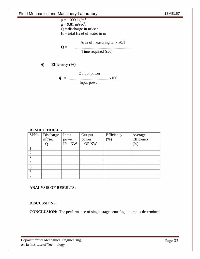
RESULT TABLE:-
Sl/No. Discharge
m3/sec
Q
Input
power
IP KW
Out put
power
OP KW
Efficiency
(%)
Average
Efficiency
(%)
1
2
3
4
5
6
7
ANALYSIS OF RESULTS:
DISCUSSIONS:
CONCLUSION: The performance of single stage centrifugal pump is determined .

Fluid Mechanics and Machinery Laboratory 18MEL57
Department of Mechanical Engineering,
Atria Institute of Technology
Page 33
EXPERIMENT No.10
RECIPROCATING PUMP
AIM: - To determine the performance of Reciprocating pump .
APPARATUS: - Reciprocating pump, stop watch , Tachometer.
THEORY:
Single acting reciprocating pump which consists of a piston which moves forwards and
backwards in a close fitting cylinder. The movement of piston is obtained by connecting rod.
The crank is rotated by means of electric motor suction and delivery pipes with suction valve
are connected to the cylinder the suction and delivery valves are one way or non return valves.
Which allow the water to flow in one direction by rotating the crank in the position θ= 0o to
1800 and 1800 – 3600 we get the valves.
SPECIFICATIONS:-
1 Supply tank - 1210x450x 450mm.
2 Measuring tank - 450x330x410mm.
3 Difference of height between two gauges = 500mm.
4 Energy meter constant = 6400 lpm/kwh.
5 Transmission efficiency = 80%.
6 No of revolution of energy meter = 10 flash.
7 Area of measuring tank = (0.45x0.33)m2.
8 rpm of pump = 3000.
9 Speed of motor = 3000 rpm.(variable).
PROCEDURE:-
1 Open the delivery valve completely.
2 Start the motor.
3 Note down the following readings. a. Vacuum gauge reading .
b. Pressure gauge reading.
c. Time required for 10 flash of energy meter.
d. Time required for 100 mm of water level in measuring tank
4 Allow sufficient time for response new conditions and note down the readings.
5 Repeat the above procedure for different speeds
OBSERVATION TABLE:-
Sl/No Suction head (Hs)
Delivery head (Hd)
Total head
H=(Hs+Hd
)+
0.5 (m)
Time required
for 10 flash
in sec
Time required for
100 mm rise of
water level in
measuring tank in
sec
mm
of Hg
M of
H2o
P
Kg/cm2
(Hd)
M of
H2o
1

Fluid Mechanics and Machinery Laboratory 18MEL57
Department of Mechanical Engineering,
Atria Institute of Technology
Page 34
2
3
4
CALCULATIONS:-
1) 1 m of Hg = 13.6m of H20 (hsx13.6/1000). m of water 2) hd = px10 m of water.
3) H = hs+hd+0.5( total head).
4) input power =IP
3600xN
IP = ------------------------- X transmission efficiency KW
CxT
N = No of flash counted = 10.
C = meter constant = 6400.
T = time in sec.
5) Output power = OP
ρ .g.Q .H
OP = KW.
1000
Where,
ρ = 1000 kg/m3.
g = 9.81 m/sec2.
Q = discharge in m3/sec.
H = total Head of water in m
Area of measuring tank x0.1
Q =
Time required (sec)
6) Efficiency (%)
Output power
ή = x100
Input power
Fluid Mechanics and Machinery Laboratory 18MEL57
Department of Mechanical Engineering,
Atria Institute of Technology
Page 35
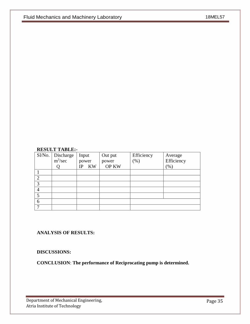
RESULT TABLE:-
Sl/No. Discharge
m3/sec
Q
Input
power
IP KW
Out put
power
OP KW
Efficiency
(%)
Average
Efficiency
(%)
1
2
3
4
5
6
7
ANALYSIS OF RESULTS:
DISCUSSIONS:
CONCLUSION: The performance of Reciprocating pump is determined.

Fluid Mechanics and Machinery Laboratory 18MEL57
Department of Mechanical Engineering,
Atria Institute of Technology
Page 36
EXPERIMENT No.11
TWO STAGE AIR COMPRESSOR
AIM:- Performance test of a two stage reciprocating air compressor.
APPARATUS:- Air compressor, stop watch.
Two stage air compressors
With two stage air compressors, the air is compressed in two stage. In between the stages, the
air is cooled.
Stage 1
Air is compressed to medium level. This is the big cylinder/piston. It moves a high volume of
air, but at a low pressure.
Cooler
Air is cooled back to a much lower level. This makes the compressor more efficient and
reduced stress on the high pressure stage.
Stage 2
The air is compressed further to the end pressure. This is the small cylinder/piston. It moves a
lower volume of air, but at an high pressure.
SPECIFICATIONS:-
1) Make CEC 2) Max. Working pressure 12kg/cm2
3) Dia. of orifice (do) = 0.014mm
4) Bore Dia. (H P) dH = 0.065m
5) Bore Dia. (L P) dL = 0.050m
6) Stroke length (L) = 0.055mm
7) Coefficient of discharge (Cd) = 0.67
8) Atmospheric pressure P1 = 1.03x10⁵ N/m2
9) Density of water = ρw= 1000kg/m3
10) Density of air = ρa = 1.207kg/m3
11) Acceleration due to gravity g = 9.81m/Sec2
12) Energy meter Constant k = 400 Rev. /Kwh
PROCEDURE:-
1) Check connection and ensure direction of rotation of compressor.
Fluid Mechanics and Machinery Laboratory 18MEL57
Department of Mechanical Engineering,
Atria Institute of Technology
Page 37
L *
2) Close shutoff valve.
3) Fill monometer with water.
4) Start the motor and observe pressure on the pressure gauge.
5) Once reaches 1kg/Sq. cm, adjust the valve opening for the same pressure.
6) Note down the reading of manometer.
7) Note down the time require for “n” flash of the energy meter.
8) Repeat the experiment for 2kg/Sq. cm, 3kg/ Sq.cm ----- , Pressure.
9) Tabulate all the readings and calculate Isothermal efficiency.
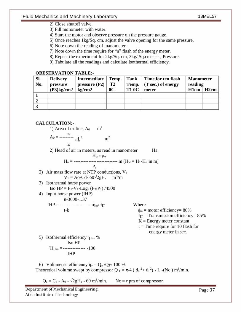
OBESERVATION TABLE:-
Sl.
No.
Delivery
pressure
(P3)kg/cm2
Intermediate
pressure (P2)
kg/cm2
Temp.
T2
0C
Tank
Temp.
T1 0C
Time for ten flash
(T sec.) of energy
meter
Manometer
reading
H1cm H2cm
1
2
3
CALCULATION:-
1) Area of orifice, A0 m2 π
A0 = --------- d 2 m2 * o
4 2) Head of air in meters, as read in manometer Ha
Hw * ρw
Ha = --------------------------- m (Hw = H1-H2 in m) Ρa
2) Air mass flow rate at NTP conductions, V1
V1 = Ao*Cd* 60√2gHa m3/m
3) Isothermal horse power
Iso HP = P1*V1*Loge (P3/P1) /4500
4) Input horse power (IHP)
n*3600*1.37
IHP = --------------------*ήm* ήT Where.
t*k ήm = motor efficiency= 80%
ήT = Transmission efficiency= 85%
K = Energy meter constant
t = Time require for 10 flash for
energy meter in sec.
5) Isothermal efficiency ή Iso %
Iso HP
Ή Iso = -------------- *100
IHP
6) Volumetric efficiency ήv = Qa /QT* 100 %
Theoretical volume swept by compressor Q T = π/4 ( d
2+ d 2)
L (Nc ) m3/min.
Qa = Cd * A0 * √2gHa * 60 m3/min. Nc = r pm of compressor
H *

Fluid Mechanics and Machinery Laboratory 18MEL57
Department of Mechanical Engineering,
Atria Institute of Technology
Page 38
7) Free air delivered (FAD) = Actual volume delivered by the compressor in normal temp.
& pressure conditions (NTP)
FAD = A0 *Cd √2gHa * 60 m3/min.
ANALYSIS OF RESULTS:
DISCUSSIONS:
CONCLUSION: The performance of Reciprocating pump is determined.

Fluid Mechanics and Machinery Laboratory 18MEL57
Department of Mechanical Engineering,
Atria Institute of Technology
Page 39
EXPERIMENT No.12
AIR BLOWER TEST RIG:-
AIM:- Performance test on air blower .
APPARATUS: - Air blower test rig, stop watch.
THEORY:
A centrifugal fan is a mechanical device for moving air or other gases. The terms "blower"
and "squirrel cage fan" (because it looks like a hamster wheel) are frequently used as
synonyms. These fans increase the speed of air stream with the rotating impellers.
BLOWERS: A blower is a machine for moving volumes of a gas with moderate increase of
pressure
CALCULATIONS:-
1) Output power:-
Qa* ρa at RTP * 9.81*hd . Output = KW
1000
Where,
Qa = actual discharge in m3/sec.
ρa at RTP = density of air at room temp in kg/m3
delivery head in meters (H d) . = ρw*hw /pa at RTP.
Water head hw = (hx-hy) m of water.
Pitot tube at out let (delivery side) reading 1 hx- m of water.
Reading 2 hy – m of water.
ρa at NTP
ρa at RTP =
(273+t)
Where, t = room temp in oC.
Density of air at NT ρa at NT = 1.293kg/m3.
Manometer reading ascending h1 = m of water.
Manometer reading descending h2 = m of water
Water head hw = (h1-h2) m of water.
Head of air ha = hw*pw meters. Actual discharge Qa =C d * A *2gha m3.
Where, Cd = coefficient of discharge = 0.62.
A = area of orifice in m2.
Diameter of orifice =0.125m A= π x (0.125)2/4 m2
g = acceleration due to gravity = 9.81m/sec.
Fluid Mechanics and Machinery Laboratory 18MEL57
Department of Mechanical Engineering,
Atria Institute of Technology
Page 40
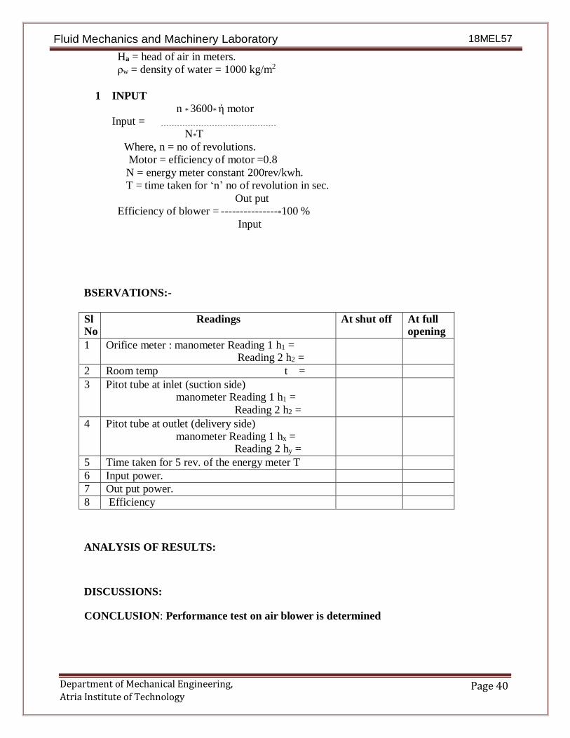
Ha = head of air in meters.
ρw = density of water = 1000 kg/m2
1 INPUT
n * 3600* ή motor Input =
N*T
Where, n = no of revolutions.
Motor = efficiency of motor =0.8
N = energy meter constant 200rev/kwh.
T = time taken for ‘n’ no of revolution in sec.
Out put
Efficiency of blower = ---------------*100 %
Input
BSERVATIONS:-
Sl No
Readings At shut off At full opening
1 Orifice meter : manometer Reading 1 h1 = Reading 2 h2 =
2 Room temp t =
3 Pitot tube at inlet (suction side) manometer Reading 1 h1 =
Reading 2 h2 =
4 Pitot tube at outlet (delivery side)
manometer Reading 1 hx = Reading 2 hy =
5 Time taken for 5 rev. of the energy meter T
6 Input power.
7 Out put power.
8 Efficiency
ANALYSIS OF RESULTS:
DISCUSSIONS:
CONCLUSION: Performance test on air blower is determined
Fluid Mechanics and Machinery Laboratory 18MEL57
Department of Mechanical Engineering,
Atria Institute of Technology
Page 41
EXPERIMENT No.12
KAPLAN TURBINE
AIM: Determine the efficiency of Kaplan Turbine at constant head
APPARATUS: Kaplan turbine test rig, tape and hook gauge
THEORY
Hydraulic (or Water) turbines are the machines, which use the energy of water (Hydro-Power)
and convert it into mechanical energy. Thus the turbines become the prime mover to run the
electrical generators to produce the electricity, Viz, Hydro-electric power. The turbines are
classified as Impulse & Reaction types. In impulse turbine, the head of water is completely
converted into a jet, which impulses the forces on the turbine. In reaction turbine, it is the
pressure of the following water, which rotates the runner of the turbine. Of many types of
turbine, the pelton wheel, most commonly used, falls into the category of impulse turbines.
While Francis & Kaplan falls in category of reaction turbines. Normally, Pelton wheel
(impulses turbine) requires high head & low discharge, while the Francis & Kaplan (reaction
turbines) require relatively low heads and high discharge. These corresponding heads and
discharges are difficult to create in laboratory size turbine from the limitation of the pumps
availability in the market. Nevertheless, at least the performance characteristics could be
obtained within the limited facility available in the laboratories. Further, understanding various
elements associated with any particular turbine is possible with this kind of facility.
DESCRIPTION:
Kaplan turbine, the reaction type which is of present concern consists of main components
such as propeller (runner) scroll casing and draft tube. Between the scroll casing and the
runner, the water turns through right angle into axial direction and passes through the runner
and thus rotating the runner shaft. The runner has four blades, which can be turned about their
own axis so that the angle inclination may be adjusted while the turbine in motion. When
runner blade angles are varied, high efficiency can be maintained over wide range of operating
Kaplan Turbine conditions. In the other words even at parts loads, when a low discharge is
following through the runner, a high efficiency can be attained in case of Kaplan turbine,
whereas this provision does not exist in Francis and propeller turbines where, the runner blade
angles are fixed and integral with hub. The actual experimental facility supplied consists of a
centrifugal pump set, turbine unit, sump tank, notch tank arranged in such a way that the whole
unit works on re circulating water system. The centrifugal pump set supplies the water from the
sump tank to the turbine through gate valve, which has the marking to the meter the known
quantity of water. The water after passing through the turbine units enters the collecting tank
through the draft tube. The water then flows back to the sump tank through the notch tank with
copulate notch for the measurement of flow rate. Additionally, the provision is also made to
estimate the rate of flow of water using the “Bend Meter “. Electrical AC generator connected
to lamp tank achieves the loading of the turbine. The provision for; measurement electrical

Fluid Mechanics and Machinery Laboratory 18MEL57
Department of Mechanical Engineering,
Atria Institute of Technology
Page 42
energy AC voltmeter and ammeter turbine speed (digital RPM indicator), Head on the turbine
(pressure gauge), are built-in on to the control panel.
SPECIFICATIONS:
Supply Pump / Motor Capacity: 10 hp 3 ph, 440V, 50Hz, AC.
Turbine: 150 mm dia. Propeller with four blades.
Run-away speed : 2500 rpm (approx.).
Max. Flow of water : 2500 1pm (approx.).
Max. Head : 10 mts. (approx.).
Loading: AC generators
Provisions: Flow rate by Rectangular notch, Notch,
d C = 0.6 (assumed).
Pressure gauge of range : 0 – 2 2 cmkg
Vacuum gauge : 0-760 mm of Hg
Electrical load : change by toggle switch (maximum
Connected load: 2000 watts).
Electric Supply : 3 ph, 440V, AC, 30A, with Neutral& Earth.
PROCEDURE:
1. Keep the gate closed. 2. Keep the electrical load at maximum, by keeping all the switches at ON –
position.
3. Press the green button of the supply pump starter and then release.
4. Slowly, open the gate so that turbine rotor picks up the speed and Attains
maximum at full opening of the gate.
5. Note down the voltage and current, speed, pressure, vacuum on the
Control panel, head over the notch, and tabulate results.
6. Close the gate & then switch off the supply water pump set.
7. Follow the procedure described below for taking down the reading for
evaluating the performance characteristics of the Kaplan turbine.
TO OBTAIN CONSTANT SPEED CHARACTERISTICS:
(Operating Characteristics)
1. Keep the gate opening at maximum. 2. For different electrical loads on turbine / generator, change the gate position, so that the
Speed is held constant. Say at 1500 rpm. See that the voltage does not exceed 250V to avoid
excess voltage on Bulbs.
3. Reduce the gate opening setting to different position and repeat (2) for different speed 1500
Rpm, 1000 rpm and tabulate the results.
4. The above readings will be utilized for drawing constant speed characteristics
i. Percentage of full load Vs Efficiency.
ii. Efficiency and BHP Vs Discharge characteristics.
TO OBTAIN CONSTANT HEAD CHARACTERISTICS:
(Main Characteristics)
1. Select the guide vane angle position. 2. Keep the gate closed, and start the pump.
Fluid Mechanics and Machinery Laboratory 18MEL57
Department of Mechanical Engineering,
Atria Institute of Technology
Page 43
3. Slowly open the gate and set the pressure on the gauge.
4. For different electrical loads, change the rotor pitch position and maintain
the constant head and tabulate the results given in Table – II.
TO OBTAIN RUN-AWAY SPEED CHARACTERISTICS:
1. Switch OFF the entire load on the turbine and the voltmeter. 2. Keep propeller vane angle at optimum position (Head, h = 0.75 2 cm kg )
3. Slowly open the gate to maximum and note down the turbine speed. This
is the run-away speed, which is maximum.
NOTE : Run-away speed is also influenced by the tightening in gland packing
of the turbine shaft. More the lightness, less the run-away speed
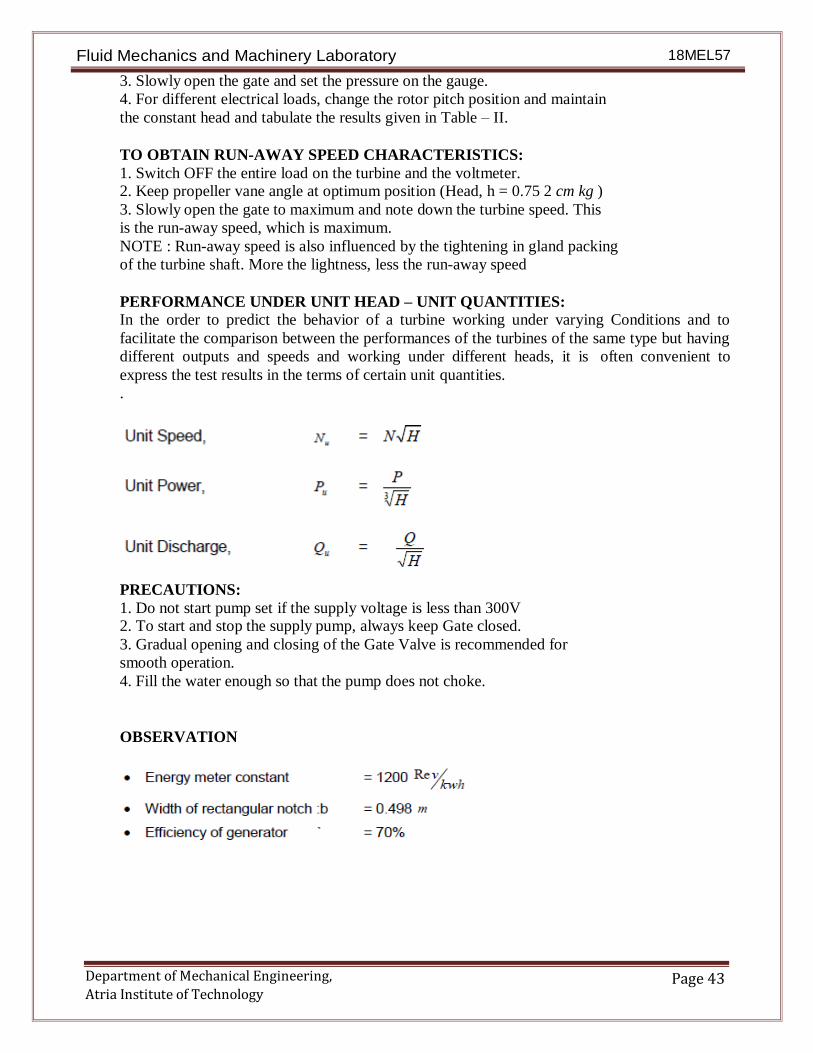
PERFORMANCE UNDER UNIT HEAD – UNIT QUANTITIES:
In the order to predict the behavior of a turbine working under varying Conditions and to
facilitate the comparison between the performances of the turbines of the same type but having
different outputs and speeds and working under different heads, it is often convenient to
express the test results in the terms of certain unit quantities.
.
PRECAUTIONS:
1. Do not start pump set if the supply voltage is less than 300V 2. To start and stop the supply pump, always keep Gate closed.
3. Gradual opening and closing of the Gate Valve is recommended for
smooth operation.
4. Fill the water enough so that the pump does not choke.
OBSERVATION

Fluid Mechanics and Machinery Laboratory 18MEL57
Department of Mechanical Engineering,
Atria Institute of Technology
Page 44
CALCULATION

Fluid Mechanics and Machinery Laboratory 18MEL57
Department of Mechanical Engineering,
Atria Institute of Technology
Page 45
Fluid Mechanics and Machinery Laboratory 18MEL57
Department of Mechanical Engineering,
Atria Institute of Technology
Page 46
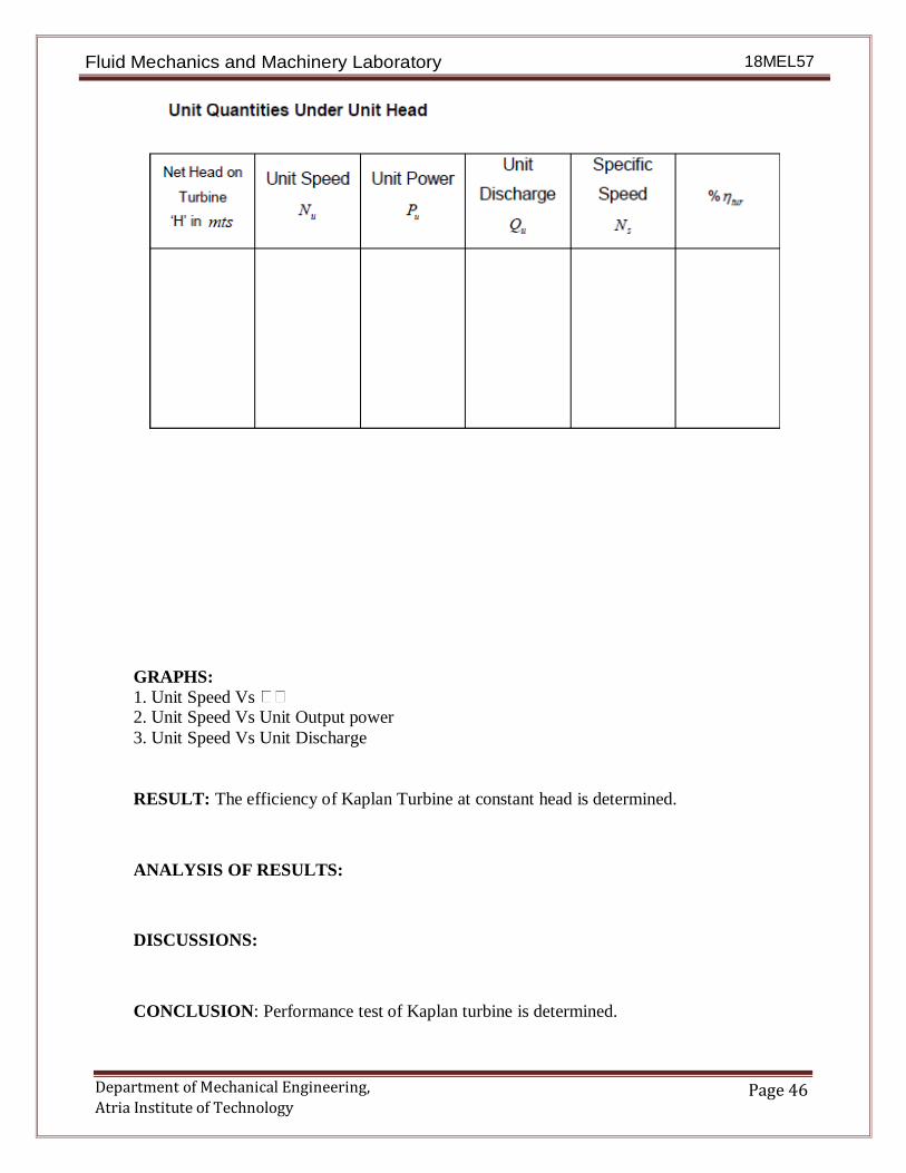
GRAPHS:
1. Unit Speed Vs 2. Unit Speed Vs Unit Output power
3. Unit Speed Vs Unit Discharge
RESULT: The efficiency of Kaplan Turbine at constant head is determined.
ANALYSIS OF RESULTS:
DISCUSSIONS:
CONCLUSION: Performance test of Kaplan turbine is determined.
Fluid Mechanics and Machinery Laboratory 18MEL57
Department of Mechanical Engineering,
Atria Institute of Technology
Page 47
FLUID MECHANICS AND MACHINERY LAB – VIVA QUESTIONS
1. Differentiate between absolute and gauge pressure ?
Absolute pressure- It is zero referenced against a perfect vacuum ,so it is equal to gauge
pressure plus atmospheric pressure.
Gauge pressure- It is zero referenced against ambient air pressure ,so it is equal to absolute
pressure minus atmospheric pressure .
2. Mention two pressure measuring instruments ?
Two pressure measuring instrument are Barometer and Manometer
3. What is the difference weight density and mass density?
Weight density is the gravitational force acting on a body Mass density is a measure of the amount of material in an object.
4. What is the difference between dynamic and kinematic viscosity?
1. Dynamic viscosity is to measure a fluid’s resistance to flow when an external force is
applied .
2. The unit of measure of dynamic viscosity is centipoise (cP).
Kinematic viscosity – It is the other way to measure the resistance flow of a fluid under the
weight of the gravity.
2. The unit of measure of kinematic viscosity is centistokes (cSt)
5. Differentiate between specific weight and specific volume ?
Specific Weight: Specific weight of a fluid is defined as the ratio of the weight of a fluid to the
volume of the fluid. Or weight of a fluid per unit volume is called its specific weight.
Specific weight = (weight of fluid)/(volume of fluid)
w = mg/V = ρg
Specific Volume: Specific volume of a fluid is defined as the ratio of the volume of a fluid to
the mass of the fluid. In other words it may also be defined as volume per unit mass of a fluid.
Specific volume = (volume of fluid)/(mass of fluid)
specific volume = V/m = 1/ρ
6. Define relative density ?
It is the ratio of the density of a substance to the density of a standard, usually water for a
liquid or solid, and air for a gas.
7. What is vacuum pressure ?
Vacuum pressure is the difference between the atmospheric pressure and the absolute pressure.
Pressure(vac) = pressure(atm) - pressure(abs)
Fluid Mechanics and Machinery Laboratory 18MEL57
Department of Mechanical Engineering,
Atria Institute of Technology
Page 48
8. What is absolute zero pressure ?
Absolute zero is the lower limit of the thermodynamic temperature scale, a state at which the
enthalpy and entropy of a cooled ideal gas reaches its minimum value, taken as 0
9. Differentiate between laminar and turbulent flow ?
Laminar flow – 1. It is a fluid flow in which the fluid layers move parallel to each other and do
not cross each other
2. The laminar flow generally occurs in the fluid flowing with low velocity
Turbulent flow- It is a fluid flow in which the fluid layers cross each other and do not move
parallel to each other
2. The turbulent flow occurs when the fluid flows with high velocity
10. How will you classify the flow as laminar and turbulent flow ?
While laminar flow is orderly turbulent flow is Random and Choatic . It is also found that a
flow in a pipe is laminar if the Reynolds number (based on diameter of the pipe) is less than
2100 and is turbulent if it is greater than 4000 . Transitional flow prevails between these two
limits.
11. Mention few discharge measuring devices ?
1. Volumetric and weight method
2. pipe flow meters based on flow contraction
- Orifice meter
- Nozzle meter
12. Why the divergent cone is longer than convergent cone in venturi meter ?
We know that in convergent section is accelerated and decelerated in divergent section from
Bernoulli equation so in convergent section fluid velocity is increases and static pressure
decreases and opposite happens in divergent section that is static pressure increases.
13. Compare the merits and demerits of venturimeter with orificemeter ?
Merits – 1. Orifices are small plates and easy to install
2. orifice meter can be easily maintained
3. measures a wide range of flow rates
Demerits – 1. Requires homogeneous fluid
2. Requires single phase liquid
3. They have low range ability
14. Why cd value is high in venturimeter than orifice meter ?
In venturi meter losses are less so cd is higher whereas in orifice meter due to convergent and
divergent cones there are more losses and hence its cd is less .
15. What is orifice plate ?
An orifice plate is a device used for measuring flow rate , for reducing pressure or for
restricting flow it is often called a restriction plate .

Fluid Mechanics and Machinery Laboratory 18MEL57
Department of Mechanical Engineering,
Atria Institute of Technology
Page 49
16. What do you mean by vena contracta ?
Vena contracta is the point in a fluid stream where the diameter of the stream is the least, and
fluid velocity is at its maximum , such as in the case of a stream issuing out of a nozzle .It is a
place where the cross section area is minimum.
17. Define coefficient of discharge ?
In a nozzle or other constriction, the discharge coefficient is the ratio of the actual discharge to
the theoretical discharge ,i.e, the ratio of the mass flow rate at the discharge end of the nozzle
which expands an identical working fluid from the same initial conditions to the Same exit
pressures.
18. write down darcy weisback’s equation ?
where the pressure loss per unit length Δp/L (SI units: Pa/m) is a function of:
ρ, the density of the fluid (kg/m3);
D, the hydraulic diameter of the pipe (for a pipe of circular section, this equals the
internal diameter of the pipe) (m);
⟨v⟩, the mean flow velocity, experimentally measured as the volumetric flow rate Q per
unit cross-sectional wetted area (m/s);
fD, the Darcy friction factor.fD is called flow coefficient λ by some
19. Draw the venturimeter and mention the parts?
Fluid Mechanics and Machinery Laboratory 18MEL57
Department of Mechanical Engineering,
Atria Institute of Technology
Page 50
21. What is the difference between friction factor and coefficient of friction?
friction is the resistance offered to the motion which is a force, whereas co-efficient of friction
is the ratio of friction to normal reaction. Normal reaction is the opposite reaction offered to the
downward force applied by the body i.e its own weight. And one more thing friction is
measured in newtons whereas co-efficient of friction is dimensionless.
22. What do you mean by major energy loss?
When a fluid is flowing through a pipe, the fluid experiences some resistance due to which
some of the energy of the fluid is lost. The viscosity causes loss of energy in the flows, which
is known as frictional loss or major energy loss
23. List down the type of minor energy losses?
When a fluid is flowing through a pipe, the fluid experiences some resistance due to
which some of the energy of the fluid is lost. This loss of energy is classified as:
i) Major energy losses: The viscosity causes loss of energy in the flows, which is known as
frictional loss or major energy loss.
ii) Minor energy losses: The loss of energy due to change of velocity of the flowing fluid in
magnitude or direction is called minor loss of energy.
24. Define turbine
It is a device which converts mechanical energy into electrical energy or hydraulic energy
into electrical energy. Turbines can also be termed as machines extracting energy from fluids.
25. What are the classifications of turbine
The main classification depends upon the type of action of the water on the turbine.
These are
(i) Impulse turbine (ii) Reaction Turbine.
(i) In the case of impulse turbine all the potential energy is converted to kinetic energy in the
nozzles. The impulse provided by the jets is used to turn the turbine wheel. The pressure inside
the turbine is atmospheric.
(ii) In reaction turbines the available potential energy is progressively converted in the turbines
rotors and the reaction of the accelerating water causes the turning of the wheel
26. Define impulse turbine.

Fluid Mechanics and Machinery Laboratory 18MEL57
Department of Mechanical Engineering,
Atria Institute of Technology
Page 51
A turbine in which the expansion of the fluid, often steam, is completed in a static nozzle
thetorque being produced by the change in momentum of the fluid impinging on curved
rotor blades.
27. Define reaction turbine.
ANS- A turbine with rotating blades curved and arranged so as to develop torque from
gradual decrease of steam pressure from inlet to exhaust.
28. Differentiate between impulse and reaction turbine
Impulse Turbine Reaction Turbine
1. In impulse turbine only kinetic energy is
used to rotate the turbine.
1. In reaction turbine both kinetic and
pressure energy is used to rotate the turbine.
2. In this turbine water flow through the nozzle
and strike the blades of turbine.
2. In this turbine water is guided by the guide
blades to flow over the turbine.
3. All pressure energy of water converted into
kinetic energy before striking the vanes.
3. In reaction turbine, there is no change in
pressure energy of water before striking.
4. The pressure of the water remains
unchanged and is equal to atmospheric
pressure during process.
4. The pressure of water is reducing after
passing through vanes.
5. Water may admitted over a part of
circumference or over the whole
circumference of the wheel of turbine.
5. Water may admitted over a part of
circumference or over the whole
circumference of the wheel of turbine.
6. In impulse turbine casing has no hydraulic
function to perform because the jet is at
atmospheric pressure. This casing serves only
to prevent splashing of water.
6. Casing is absolutely necessary because the
pressure at inlet of the turbine is much higher
than the pressure at outlet. It is sealed from
atmospheric pressure.
7. This turbine is most suitable for large head
and lower flow rate. Pelton wheel is the
example of this turbine.
7. This turbine is best suited for higher flow
rate and lower head situation.
29. What is the function of draft tube?
In power turbines like reaction turbines, Kaplan turbines, or Francis turbines, a diffuser tube is
installed at the exit of the runner, known as draft tube.[1] In an impulse turbine the available
head is high and there is no significant effect on the efficiency if the turbine is placed a couple
of meters above the tail race. But in the case of reaction turbines, if the net head is low and if
the turbine is installed above the tail race, there can be appreciable loss in available pressure
head. If the pressure at the exit of the turbine is lower than the pressure of fluid in the tail race,
a back flow of liquid into the turbine can result in significant damage.

Fluid Mechanics and Machinery Laboratory 18MEL57
Department of Mechanical Engineering,
Atria Institute of Technology
Page 52
30. Define specific speed of turbine.
The specific speed value for a turbine is the speed of a geometrically similar turbine which
would produce unit power (one kilowatt) under unit head (one meter).[6] The specific speed of
a turbine is given by the manufacturer (along with other ratings) and will always refer to the
point of maximum efficiency. This allows accurate calculations to be made of the turbine's
performance for a range of heads.
31. What are the main parameters in designing a Pelton wheel turbine?
The specific speed parameter is independent of a particular turbine's size.
Compared to other turbine designs, the relatively low specific speed of the Pelton wheel,
implies that the geometry is inherently a "low gear" design. Thus it is most suitable to being
fed by a hydro source with a low ratio of flow to pressure, (meaning relatively low flow and/or
relatively high pressure).
The specific speed is the main criterion for matching a specific hydro-electric site with the
optimal turbine type. It also allows a new turbine design to be scaled from an existing design of
known performance.
32. What is breaking jet in Pelton wheel turbine?
When the nozzle is completely closed by moving the spear in the forward direction, the amount
of water striking the runner reduces to zero. But the runner due to inertia goes on revolving for
a long time. To stop the runner in a short time, a small nozzle is provided which directs the jet
of water on the back of vanes. This jet of water is called Breaking Jet.
33. What is the function of casing in Pelton turbine?
The function of casing is to prevent the splashing of water and to discharge water to tail race.
The casing of Pelton Wheel does not perform any Hydraulic function.
34. Draw a simple sketch of Pelton wheel bucket.
35. What is the function of surge tank fixed to penstock in Pelton turbine?
To overcome this problem, a Storage Reservoir called as “Pen Stock” is fitted at some opening
made on the pipe line in order to store Water when the Valve is suddenly closed, or to
discharge Water when increased discharged is required. Such a Storage Reservoir is known as
“Surge Tank”.
Fluid Mechanics and Machinery Laboratory 18MEL57
Department of Mechanical Engineering,
Atria Institute of Technology
Page 53
Functions of Surge Tank.
i) To control the Pressure Variations, due to rapid changes in the pipeline flow, thus
eliminating Water Hammer possibilities.
ii) To regulate the flow of Water to the Turbine by providing necessary retarding Head of
Water.
36. How the inlet discharge is controlled in Pelton turbine?
The energy available at the inlet of the turbine is only Kinetic Energy. The pressure at the inlet
and outlet is atmospheric pressure. The nozzle increases the kinetic energy of the water flowing
through the penstock. The amount of water striking the buckets is controlled by providing a
spear in the nozzle. When the spear is pushed forward, the amount of water striking the runner
is reduced and when the spear is pushed back, the amount of water striking the runner
increases.
37. What is water hammer?
Water hammer is a pressure surge or wave caused when a fluid (usually a liquid but sometimes
also a gas) in motion is forced to stop or change direction suddenly (momentum change).
Water hammer is a commonly observed phenomenon taking place during a fluid flow.
Presence of water hammer can be easily detected by the noise it makes. Noise is not the final
effect of water hammer but just an indication of it. Water hammer has multiple adverse effects
on steam systems. Water hammer can damage equipments like flow meters which are installed
on the steam network
38. What do you mean by head race?
Some water wheels are fed by water from a mill pond, which is formed when a flowing stream
is dammed. A channel for the water flowing to or from a water wheel is called a mill race. The
race bringing water from the mill pond to the water wheel is a head race
39. What do you mean by tail race?
Some water wheels are fed by water from a mill pond, which is formed when a flowing stream
is dammed. A channel for the water flowing to or from a water wheel is called a mill race. the
one carrying water after it has left the wheel is commonly referred to as a tail race.
40. What is the difference between propeller and Kaplan turbine?
The Kaplan is of the propeller type, similar to an airplane propeller. The difference between the
Propeller and Kaplan turbines is that the Propeller turbine has fixed runner blades while
the Kaplan turbine has adjustable runner blades. It is a pure axial flow turbine uses basic
aerofoil theory.
41. Mention the parts of Kaplan Turbine ?
The main Parts of Kaplan Turbine are:
SCROLL CASING : The water from the penstocks enters the scroll casing and
then moves to the guide vanes. ...
GUIDE VANE MECHANISM: The Guide Vanes are fixed on the Hub.
HUB: For Kaplan Turbine, the shaft of the turbine is vertical.

Fluid Mechanics and Machinery Laboratory 18MEL57
Department of Mechanical Engineering,
Atria Institute of Technology
Page 54
42. Differentiate between inward and outward flow reaction turbine ?
Inward flow reaction hydro turbine water enter at the outer periphery,
flow inward and toward the centre of the turbine and discharges at the
outer periphery
Out ward flow reaction hydro turbine water enter at the inner periphery
flow out ward and discharge at the outer periphery
43. what is the difference between Francis turbine and Modern Francis Turbine ?
• In Kaplan turbine water enters axially and leaves axially, while in
Francis turbine water enters the runner radially and exits axially.
• The Kaplan turbine runner has 3-8 blades while Francis turbine runner
has 15-25 blades in general.
• Kaplan turbine has a higher efficiency than Francis turbine.
• Kaplan turbine is smaller and compact compared to Francis turbine.
44. What is mixed flow turbine ? Give an example
A mixed flow turbine has a similar ability with the benefit of lower
velocity ratio operation. Ex : Francis Turbine
45. Why draft tube is not required for impulse turbine ?
Pelton wheels are impulse turbines so they utilise only kinetic energy to turn. So there
is no requirement for a draft tube which is a requirement for reaction turbines where
both kinetic and pressure energy is utilised like a Francis and kaplan turbines.
46. How turbines are classified based on head. Give an example
Based on the head under which turbine works:
High head, impulse turbine. e.g : Pelton turbine.
Medium head,reaction turbine. e.g : Francis turbine.
Low head, reaction turbine. e.g : Kaplan turbine, propeller turbine.
47. How turbines are classified based on flow .Give an example
Tangential flow: water flows in a direction tangential to path of rotational, i.e.
Perpendicular to both axial and radial directions.
Turbines can be either reaction or impulse types. The turbines type indicates the
manner in which the water
causes the turbine runner to rotate. Reaction turbine operates with their runners fully
flooded and develops
torque because of the reaction of water pressure against runner blades. Axial flow :
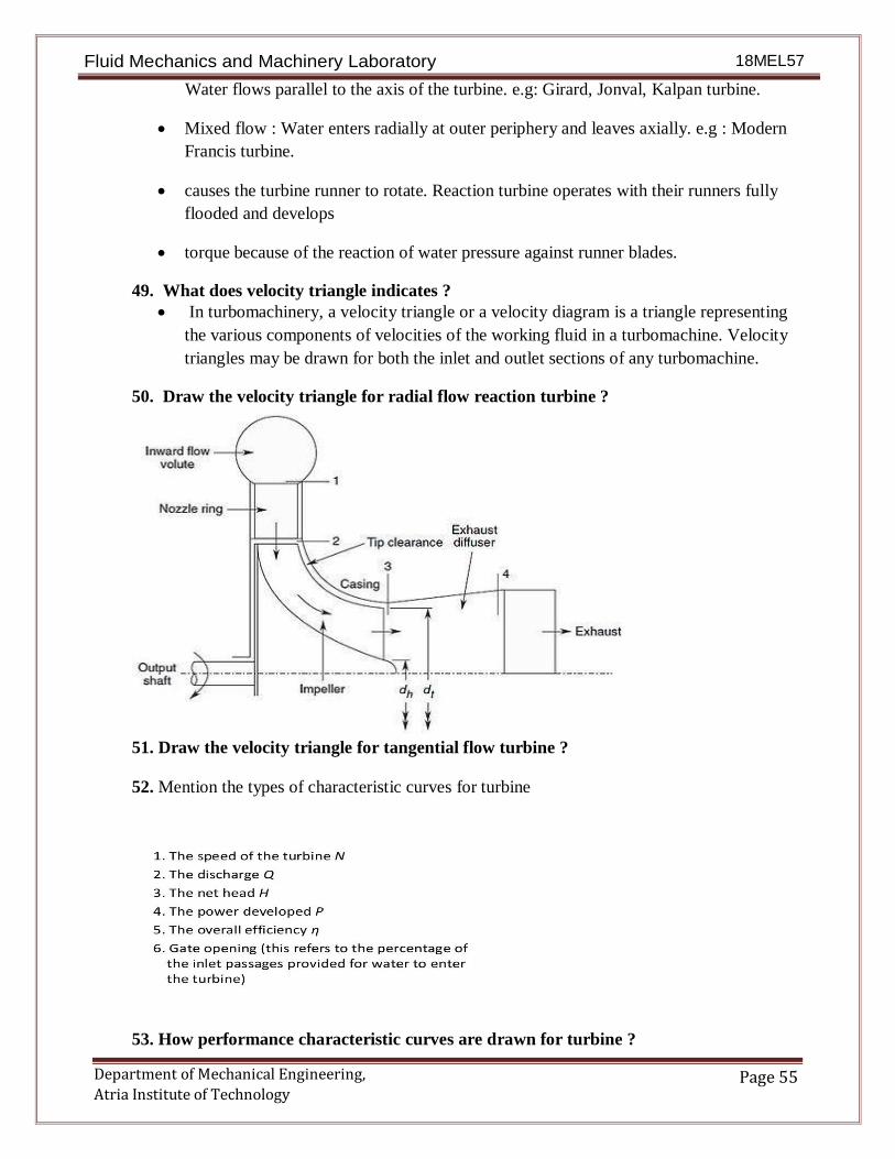
Fluid Mechanics and Machinery Laboratory 18MEL57
Department of Mechanical Engineering,
Atria Institute of Technology
Page 55
Water flows parallel to the axis of the turbine. e.g: Girard, Jonval, Kalpan turbine.
Mixed flow : Water enters radially at outer periphery and leaves axially. e.g : Modern
Francis turbine.
causes the turbine runner to rotate. Reaction turbine operates with their runners fully
flooded and develops
torque because of the reaction of water pressure against runner blades.
49. What does velocity triangle indicates ?
In turbomachinery, a velocity triangle or a velocity diagram is a triangle representing
the various components of velocities of the working fluid in a turbomachine. Velocity
triangles may be drawn for both the inlet and outlet sections of any turbomachine.
50. Draw the velocity triangle for radial flow reaction turbine ?
51. Draw the velocity triangle for tangential flow turbine ?
52. Mention the types of characteristic curves for turbine
53. How performance characteristic curves are drawn for turbine ?

Fluid Mechanics and Machinery Laboratory 18MEL57
Department of Mechanical Engineering,
Atria Institute of Technology
Page 56
Constant Head Curve-
In this head and gate opening is kept constant ..thus for every value of speed we get
corresponding values of power and discharge..thus overall efficiency can be calculated
Constant Speed Curve -
In this speed and head is kept constant.thus we can find out variation in power and efficiency
wrt discharge...it also helps tells us about the minimum discharge needed to overcome the
friction
Constant Efficiency Curve -
Obtained at different gate openings.thus for a given efficiency there are two values of
discharge and speeds. If efficiency is maximum then we get only one value.
They are helpful in determining the zone of constant efficiency and for prediction of
performance of turbines at different efficiencies
54. Mention the type of efficiencies calculated for turbine ?
1. Diagram Efficiency of Steam Turbine or Blading Efficiency of Steam Turbine 2. Nozzle Efficiency Of Steam Turbine
3. Gross or Stage Efficiency Of Steam Turbine
55. Define pump ?
A device that raises, transfers, delivers, or compresses fluids or that attenuates gases
especially by suction or pressure or both
56. How pumps are classified ?
57. Differentiate pump and turbine ?
Pump vs Turbine Pump and turbine are two devices that are widely used in many industries. The turbine is a

Fluid Mechanics and Machinery Laboratory 18MEL57
Department of Mechanical Engineering,
Atria Institute of Technology
Page 57
device that is capable of gathering energy and converting it to work.
58. Define Rotodynamic pump ?
A rotodynamic pump is a kinetic machine in which energy is continuously imparted to
the pumped fluid by means of a rotating impeller, propeller, or rotor, in contrast to a
positive displacement pump in which a fluid is moved by trapping a fixed amount of
fluid and forcing the trapped volume into the pump's discharge.
59. Define Positive displacement pump ?
A Positive Displacement Pump has an expanding cavity on the suction side and a
decreasing cavity on the discharge side. Liquid flows into the pumps as the cavity on
the suction side expands and the liquid flows out of the discharge as the cavity
collapses.
60. Differentite between rotodynamic and positive displacement pump ?
The main difference between these types of pumps and centrifugal is that positive
displacement pumps will move fluid at the same speed regardless of the pressure on the
inlet end and centrifugal pumps will not.
61. Define Cavitations in pump
Pump cavitations is the formation and subsequent collapse or implosion of vapor bubbles in a
pump. It occurs when gas bubbles are formed in the pump due to drop in absolute pressure of
the liquid below vapor pressure.
62. What is the need for priming in pump?
Priming is a process in which a portion of suction pipe, casing and a portion of delivery
pipe is filled with liquid to be pumped in order to remove air from these portions. It is done in
order to create necessary suction while pump is in working condition. And to avoid cavitations
effect.
63. Give examples for roto dynamic pump.
Module two: 1 March 2009 - 5 March 2009 losses in fluid systems including liquid, gas
and sludge system calculation principles and design of rotodynamic and positive displacement
pumps and compressors cavitation control valve design and behaviour matching of machines
and systems pump intakes for clean and wastewater drive system, control and operating
economics pump selection and maintenance fluid transient and prevention simulation
Fluid Mechanics and Machinery Laboratory 18MEL57
Department of Mechanical Engineering,
Atria Institute of Technology
Page 58
64. Give examples for positive displacement pump.
Positive Displacement pumps are generally used for specialist applications such as for
pumping viscous liquids or liquids that contain suspended or fragile solids. These pumps are
typically not capable of such a high flow rate as say, a centifrugal pump, but they are capable
of producing much higher pressures. - See more at:
65. Mention the parts of centrifugal pump.
66. Mention the types of casing used in centrifugal pump.
The three basic casing types primarily used for centrifugal pumps are:
single volute
double volute and
vaned diffuser.
Of these, the most common - at least for low- to medium-flow, single-stage pumps - is the
single volute, with double volutes used more for larger, single-stage pumps handling liquids
without solids, and vaned diffusers primarily applied to multistage pumps.
67. Why the foot valve is fitted with strainer?
To prevent debris and small stones being sucked into it.
68. Why the foot valve is non return type?
it allows the water to flow in only one direction
69. Differentiate between volute casing and vertex casing.
An impeller
A volute or diffuser style casing
A shaft
Shaft sleeves
Bearings
A sealing arrangement

Fluid Mechanics and Machinery Laboratory 18MEL57
Department of Mechanical Engineering,
Atria Institute of Technology
Page 59
Volute casing, which is sometimes fitted with a double volute consisting of two
volutes offset by 180° to balance the radial thrust.
Vortex volute whose volute cross-section is markedly asymmetrical when viewed in the
meridional section.
70. What is the function of volute casing?
it is designed to accommodate fluid coming out of periphery of impeller. The velocity
of fluid is constant throught the casing as per theoretical design, because water keeps on
adding up from start to end of casing.
71. What is the function of guide vanes?
Guide Vanes arc installed in the turbine to regulate the quantity of water to the runner
with change in load.These are operated by two servomotors through guide vane operating
mechanism via links & levers.
The servomotors get signals from Governor.
The guide vanes are of aero flow section, which allows the flow of water without formation of
eddies in all positions.
Depending upon silt flow, the guide vanes may be made of mild steel or stainless steel with
integral machined which are drilled for grease lubrication of bushes
72. Why vanes are curved radially backward?
Centrifugal pumps do not always have backward curved vanes. But when they do, it is mostly
for fluids in the incompressible regime of operation such as water. For compressible operation
of fluids such as air, forward curve-vaned centrifugal pumps are used.
73. What is the function of impeller?
An impeller is a rotating component of a centrifugal pump, usually made of iron, steel,
bronze, brass, aluminum or plastic, which transfers energy from the motor that drives the pump
to the fluid being pumped by accelerating the fluid outwards from the center of rotation. The
velocity achieved by the impeller transfers into pressure when the outward movement of the
fluid is confined by the pump casing.

Fluid Mechanics and Machinery Laboratory 18MEL57
Department of Mechanical Engineering,
Atria Institute of Technology
Page 60
74. Mention the parts of impeller used.
Impellers are usually short cylinders with an open inlet (called an eye) to accept
incoming fluid, vanes to push the fluid radially, and a splined, keyed, or threaded bore to
accept a drive-shaft.
75. Define specific speed of pump.
commonly-used equation for specific speed is as follows:
76. Mention the types of characteristic curves for pump.
The characteristic curve's shape is primarily determined by the pump type (i.e. impeller,
pump casing or specific speed. Secondary influences such as cavitation, manufacturing
tolerances, size and physical properties of the fluid handled (e.g. viscosity, solids transport or
pulp pumping).
77. How performance characteristic curve s are drawn from pump?
For a specified impeller diameter and speed, a centrifugal pump has a fixed and
predictable performance curve. The point where the pump operates on its curve is dependent
upon the characteristics of the system in which it is operating, commonly called the System
Head Curve..or, the relationship between flow and hydraulic losses in a system. This
representation is in a graphic form and, since friction losses vary as a square of the flow rate,
the system curve is parabolic in shape.
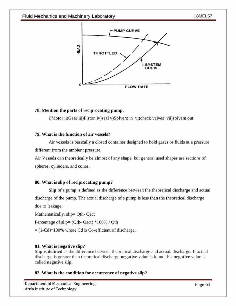
Fluid Mechanics and Machinery Laboratory 18MEL57
Department of Mechanical Engineering,
Atria Institute of Technology
Page 61
78. Mention the parts of reciprocating pump.
i)Motor ii)Gear iii)Piston iv)seal v)Solvent in vi)check valves vii)solvent out
79. What is the function of air vessels?
Air vessels is basically a closed container designed to hold gases or fluids at a pressure
different from the ambient pressure.
Air Vessels can theoretically be almost of any shape, but general used shapes are sections of
spheres, cylinders, and cones.
80. What is slip of reciprocating pump?
Slip of a pump is defined as the difference between the theoretical discharge and actual
discharge of the pump. The actual discharge of a pump is less than the theoretical discharge
due to leakage.
Mathematically, slip= Qth- Qact
Percentage of slip= (Qth- Qact) *100% / Qth
= (1-Cd)*100% where Cd is Co-efficient of discharge.
81. What is negative slip?
Slip is defined as the difference between theoretical discharge and actual. discharge. If actual
discharge is greater than theoretical discharge negative value is found this negative value is
called negative slip.
82. What is the condition for occurrence of negative slip?

Fluid Mechanics and Machinery Laboratory 18MEL57
Department of Mechanical Engineering,
Atria Institute of Technology
Page 62
When pumps have long suction pipe, low delivery head and have high speed. It happens
because in such case inertia pressure in suction pipe will be large in comparison pressure
outside delivery valve, which may cause delivery valve to open before suction stroke is
completed. Some liquid is thus pushed directly into delivery pipe even before delivery stroke
is commenced, which results in making actual discharge more than theoretical discharge.
83. What does indicator diagram indicates?
a graphical or other representation of the cyclic variations of pressure and volume within the
cylinder of a reciprocating engine obtained by using an indicator
84. What is the difference between actual and ideal indicator diagram?
Heat losses. In the theoretical cycle are null, but very sensitive, however, in the actual cycle.
As the cylinder is cooled to ensure the smooth operation of the piston, a certain portion of heat
from the fluid is transferred to the walls. Expansion compression lines are therefore adiabatic
but polytropic with exponent n, k different. Because the fluid undergoes heat loss evidently
has: for expansion, n> k, and for compression figure.
Combustion is not instantaneous. In the theoretical cycle, it is assumed that the combustion
takes place at constant volume, is therefore instantaneous in the real cycle, however,
combustion takes some time. If ignition take place precisely at TDC, combustion would occur
while the piston moves away from that point, and serious pressure value lower than expected,
with the corresponding loss of useful work .
It is therefore necessary to advance the ignition so that combustion can take place, for the most
part, when the piston is in the proximity of PMS This produces a rounding of the theoretical
line 2-3 heat input and therefore a loss of useful work represented by the area B. But this loss is
of markedly lower amount that would not advance the ignition.
85. Briefly explain Gear pump.
A gear pump uses the meshing of gears to pump fluid by displacement.[1] They are one of the
most common types of pumps for hydraulic fluid power applications.
Gear pumps are also widely used in chemical installations to pump high viscosity fluids. There
are two main variations; external gear pumps which use two external spur gears, and internal
gear pumps which use an external and an internal spur gears (internal spur gear teeth face
inwards, see below). Gear pumps are positive displacement (or fixed displacement), meaning
they pump a constant amount of fluid for each revolution. Some gear pumps are designed to
function as either a motor or a pump.
86. Differentiate between internal gear pump and external gear pump.
External
An external gear pump uses two external gears (Figure 1, below) that displace non-lubricating
fluids (gears are oil lubricated). The mechanism is usually driven by one of the toothed gears,
which in turn drives the other. Three factors are involved in the regulation of flow: volume of

Fluid Mechanics and Machinery Laboratory 18MEL57
Department of Mechanical Engineering,
Atria Institute of Technology
Page 63
cavity between the teeth, speed of gears, and the amount of fluid that slips back to the inlet
(tolerance dependant) via the mechanism. There are three main types of external gears: spur,
helical and herringbone. Helical and herringbone deliver more flow at higher pressure while
also being quieter, but may require a greater inlet pressure than spur (EPW, 2012)
Figure 1: External Gear Pump – Exterior-bearing type. Arrows indicate flow direction and
movement of gears.
Internal
An internal gear pump uses internal and external gears (Figure 2, below). The gears themselves
are lubricated by the fluid, which is of a lubricating nature. The internal design is seen as being
reliable, easy to operate and maintain – due to only two moving parts being present. Only one
drive gear is required for the mechanism to function but it is possible to use two. The pump
will usually contain at least one bushing (EPW, 2012). The design can also be modified to
include a crescent shaped portion that improves performance when pumping high viscosity
fluids (Figure 2). Internal gear pumps have relatively low speed and inlet pressure
requirements.

Fluid Mechanics and Machinery Laboratory 18MEL57
Department of Mechanical Engineering,
Atria Institute of Technology
Page 64
87. Briefly explain vane pump.
A rotary vane pump is a positive-displacement pump that consists of vanes mounted to a rotor that rotates inside of a cavity. In some cases these vanes can have variable length and/or
be tensioned to maintain contact with the walls as the pump rotates. It was invented by Charles
C. Barnes of Sackville, New Brunswick, who patented it on June 16, 1874.[1][2] There have
been various improvements, including a variable vane pump for gases (1909)
88. What is rotary pump?
A rotary vane pump is a positive-displacement pumpthat consists of vanes mounted to a rotor
that rotates inside of a cavity. In some cases these vanes can have variable length and/or be
tensioned to maintain contact with the walls as the pump rotates.
89. Draw the velocity triangle for centrifugal pump.
90. Draw the indicator diagram for reciprocating pump.

Fluid Mechanics and Machinery Laboratory 18MEL57
Department of Mechanical Engineering,
Atria Institute of Technology
Page 65
91. What is the amount of work saved by air vessel?
92. Mention the merits and demerits of centrifugal pump.
Advantages of centrifugal pump
As there is no drive seal so there is no leakage in pump
It can pump hazardous liquids
There are very less frictional losses
There in almost no noise
Pump has almost have 100 efficiency
Centrifugal pump have minimum wear with respect to others
There is a gap between pump chamber and motor, so there is no heat transfer between
them
Because of the gap between pump chamber and motor, water cannot enter into motor
Centrifugal pump use magnetic coupling which breakup on high load eliminating the
risk of damaging the motor
Disadvantages of centrifugal pump
Because of the magnetic resistance there is some energy losses
Unexpected heavy load may cause the coupling to slip
Role of Air vessels in reciprocating pump
1. Uniform velocity during suction and discharge
2. Reduces head loss
3. Act as a reservoir of the fluid

Fluid Mechanics and Machinery Laboratory 18MEL57
Department of Mechanical Engineering,
Atria Institute of Technology
Page 66
ferrous particles in liquid are problematic when you are using magnetic drive. This is
because particle collect at impeller and cause the stoppage of pump after some time
93. Mention the merits and demerits of reciprocating pump.
Advantages of reciprocating pump
High efficiency
No priming needed
Can deliver water at high pressure
Can work in wide pressure range
Continuous rate of discharge
Disadvantages of reciprocating pump
More parts mean high initial cost
High maintenance cost
No uniform torque
Low discharging capacity
Pulsating flow
Difficult to pump viscous fluid
High wear in parts
94. What is separation in reciprocating pump?
If the pressure in the cylinder is below the vapour pressure , dissolved gasses will be liberated
from the liquid and cavitations will takes place . The continuous flow of liquid will not exit
which means separation of liquid takes place. The pressure at which separation takes place is
called separation pressure and head corresponding to the separation pressure is called
separation pressure head.
95. Differentiate single acting and double acting reciprocating pump
In single acting pump, there is one suction valve and one delivery valve. On the backward
stroke of the piston, the suction valve opens and water enters into the cylinder space. On the
forward stroke, the suction valve closes and delivery valve opens, the water is
In the double acting pump, there are two suction valves and two delivery vales one in the front
and one in the rear. When the piston moves backward, the suction valve in the front opens and
delivery valve in the rear opens and water is forced through it. When the piston moves forward,
the suction valve in the rear opens and delivery valve in the front opens and water is forced
through it.