krl53802 LAT Manual - Krell Industries · The LAT Series Lossless Acoustic Transducers Owner’s...
33
OWNER’S REFERENCE LAT THE LAT SERIES LOSSLESS ACOUSTIC TRANSDUCERS
Transcript of krl53802 LAT Manual - Krell Industries · The LAT Series Lossless Acoustic Transducers Owner’s...
O W N E R ’ S R E F E R E N C E
L A TT H E L AT S E R I E S
L O S S L E S S A C O U S T I C
T R A N S D U C E R S
The LAT SeriesLossless Acoustic Transducers Owner’s Reference, v03.0
Krell Industries, Inc.45 Connair RoadOrange, CT 06477-3650 USA
TEL 203-799-9954FAX 203-891-2028E-MAIL [email protected] http://www.krellonline.com
This product complies with the EMC directive (89/336/EEC) and the low-voltage directive(73/23/EEC).
This product is manufactured in the United States of America. Krell® is a registered trademark of Krell Industries, Inc., and is restricted for use byKrell Industries, Inc., its subsidiaries, and authorized agents. Krell CAST™, Krell Current Mode™, Krell HEAT™, and LAT™ are trademarks of KrellIndustries, Inc. All rights reserved. All other trademarks and tradenames are registered to their respective companies.
© 2001 by Krell Industries, Inc. All rights reserved P/N 305139
1iii
ContentsList of Illustrations, page iv
Foreword, page v
A Letter from Dan D’Agostino, page 1
SECTION ONE: About Krell, page 2
The Krell Legacy, Ensuring Maximum Performance, and Definition of Terms
SECTION TWO: Unpacking and Placement, page 7
Opening the LAT–1 and the LAT–C Shipping Crate
Opening the LAT–2 Shipping Box
SECTION THREE: Anatomy of a Loudspeaker, page 14
Features and Benefits of the LAT Design
SECTION FOUR: Connecting a LAT Series Loudspeaker to Your System, page 22
SECTION FIVE: Krell HEAT: Home Theater Technology, page 23
WARRANTY, page 25
RETURN AUTHORIZATION PROCEDURE, page 27
iv
List of IllustrationsFigure 1, page 11
Two-Channel LAT Placement Scenario
Figure 2, page 14
LAT–1 Front Panel and Grill
Figure 3, page 15
LAT–1 Back and Side Panels
Figure 4, page 16
LAT–C Front Panel and Grill
Figure 5, page 17
LAT–C Pivot Mechanism, Leg Assembly, and Crossovers
Figure 6, page 18
LAT–2 Front Panel and Grill
Figure 7, page 19
LAT–2 Back and Side Panels
Figure 8, page 24
A Krell HEAT (Home Theater) System Placement Scenario
v
Foreword
The design and manufacture of loudspeakers is a new venture for Krell, but thereasons for making them are not new at all.
For more than two decades, Krell components have been the choice of discerningaudiophiles all over the world. Krell customers care deeply about music, and theydemand the most lifelike music reproduction possible. Krell Industries, Inc., wasfounded and exists to meet the expectations of those listeners.
Loudspeakers are an integral link in an audio system. With the right loudspeakers,you hear music with its original definition, precision, and clarity. Krell’s losslesstechnology combines the benefits of enclosure design, materials selection, andelectronics design and configuration to ensure that you hear music exactly as itwas recorded—nothing more, nothing less.
With the Lossless Acoustic Transducer (LAT), Krell has achieved its goal: a loud-speaker that is uniquely capable of delivering music with the same confidence andaccuracy as Krell’s other legendary components.

1
A Letter from Dan D’Agostino
Dear Audio Enthusiast,
Thank you for your purchase of the Lossless Acoustic Transducer.
For more than thirty years I have been designing audio components for audiophileswho share my passion for music and its reproduction. The Lossless AcousticTransducer (LAT) and the LAT Series of loudspeakers are the result of my ongoingquest to design a complete audio system.
Krell’s newest line of audio components (compact disc players, preamplifiers, andpower amplifiers) features Current Audio Signal Transmission technology (CAST).With the advent of CAST—for the very first time—a discrete, all-Krell signal chainis a reality. With CAST-equipped components you can hear how an unbroken,current signal path impacts music reproduction. Reference quality playback hasalways been my dream. CAST has made this dream a reality.
When I looked for, but could not find, a loudspeaker that offered the impact,immediacy, and resolution of CAST components, I decided to build one myself.The first Krell loudspeaker, the LAT–1, uses the best of acoustical engineering, elec-trical engineering, and materials science to enhance music reproduction.
I have taken care at every turn to ensure that every part of a LAT loudspeaker—thedrivers, the crossover, and the aluminum enclosure—has been designed to trans-mit the whole music program to you; nothing is added or subtracted.
The LAT Series signals a new era at Krell Industries, in which every componentin the system is a Krell component. I designed the LAT loudspeakers to reproduceall the power and grace that a Krell system can deliver. A Krell system composedof LAT loudspeakers with my other Krell components provides the most thrilling,lifelike playback I have heard yet. Thank you for your appreciation of my art.
Sincerely,
Daniel D’Agostino
Chief Executive Officer
2
SECTIONONEAbout Krell
This section describes the Krell Legacy, Krell’s innovative loudspeaker design andtechnology, and defines key terms used in this reference.
The Krell Legacy
“I design every Krell component to set the standard for workmanship, style, and performance.”
Dan D’Agostino
High-end audio is a demanding pursuit—an ongoing quest for excellence inmusic reproduction that drives equipment manufacturers to strive for the absolutein design and performance. With a keen understanding of this passionate drive,Krell Industries, Inc., was founded in 1980.
Over the past two decades, Krell has earned a distinguished reputation for engineer-ing innovation and product excellence. The company’s history is replete with productintroductions that have deeply impacted the high-end audio industry. The mostdiscriminating audiophiles and product reviewers have consistently recognized Krellcomponents for standard-setting performance.
The Lossless Acoustic Transducer (LAT) represents the next era at Krell Industries—the era of loudspeaker design and manufacture — which will join the ongoinglegacy of Krell amplifiers. For two decades, Krell C.E.O. Dan D’Agostino hasbuilt amplifiers legendary for their ability to deliver optimum performance for anyloudspeaker. This experience has yielded invaluable insights about the nature ofloudspeaker design, which Krell has characteristically incorporated into the LATSeries.
The LAT Series of Loudspeakers
The LAT–1, a reference-caliber loudspeaker, employs an all-aluminum enclosurethat remains sonically inert, with a baffle that absorbs vibrations and houses custom-made drivers, and a robust, high-power crossover—a loudspeaker capable ofhandling the legendary power of Krell amplifiers, while maintaining pinpointaccuracy and resolution.
continued �3
The LAT–C, the first high performance center channel, is manufactured with allof the crossover, enclosure, and driver technologies of the LAT–1. Designed to beoperated as a full-range loudspeaker, the LAT–C center channel loudspeakerperfectly complements the LAT–1. Together, these loudspeakers form the mostextraordinary home theater loudspeaker system available.
The magnetic shielding and horizontal driver array of the LAT–C allows for ease ofinstallation above or below a video screen. In addition, multiple locator positions inthe stand assembly allow for the optimal on-axis setup of the loudspeaker foralmost all scenarios.
The LAT–2 is a vented two-way loudspeaker designed for a two-channel systemdemanding high quality performance in a small space. This loudspeaker is alsothe perfect complement to the LAT–1 and LAT–C loudspeakers in a home theatersystem. Crossover, enclosure, and driver technologies used in the LAT–1 have beenapplied to the design of the LAT–2.
Unparalleled Sonic Performance
From the first Krell product—the KSA–100—to the present, Dan D’Agostino hascontinually “pushed the envelope” of performance in his search for greater amplifierpower, and now, loudspeaker response. His exploration of technologies, driven byhis never-ending quest to elevate the standard of excellence, has resulted in break-through audio designs. Over the years, the Krell line of power amplifiers, includingbenchmark products such as the KRS–100, KRS–200, and the Audio Standardmodels, has established a legacy of unparalleled sonic performance. The LATSeries brings the Krell level of performance to the loudspeaker.
Dan D’Agostino remains committed to the development of new designs andtechnologies. And the Krell legacy will continue to evolve with products that deliverinnovative engineering, perfection in build quality, and outstanding audio performance.
(SECTION ONE: About Krell continued)
4
Ensuring Maximum Performance
The function of the LAT Series of loudspeakers is to repro-duce the full spectrum of the music program with absolutefidelity, and to deliver its full emotional impact without col-oration — an exact reproduction of the audio amplifier’soutput signal.
The Krell Lossless Acoustic Transducer (LAT) is the latest innovation in a longline of Krell components. The innovative technologies and design of the LAT Seriesof loudspeakers includes sophisticated crossover networks, a precisely machinedenclosure, and drivers designed to efficiently transmit power while negatingdistortions.
Innovative Loudspeaker Technology and Design
CrossoverThe LAT–1 and LAT–C crossovers feature robust construction that divides thecircuit among three discrete circuit cards—one each for the woofer, midrange,and tweeter networks. The LAT–2 loudspeaker has a two-way crossover design,with the woofer and tweeter together on a single circuit board. Each printed circuitboard for a LAT loudspeaker is fashioned of 1/8-inch fiberglass with 4-ounce coppertraces for superior current flow. Air core inductors and banks of potted WIMAcapacitors ensure tight tolerances and high linearity during high power levels.
EnclosureContinuing in the tradition of the Master Reference Subwoofer, a LAT Seriesloudspeaker enclosure is constructed entirely of aluminum. “Aluminum is the bestmaterial for the job,” C.E.O. Dan D’Agostino explains. “Other than concrete andlead, which are not practical choices, aluminum is the only material that possessesthe ideal combination of structural rigidity and resonance damping characteristics.Within the audio passband, our cabinets are sonically inert—something you cannotsay about any wood or wood derivative.”
Krell’s knowledge of aluminum extrusion technology has yielded an enclosure that isas purposeful as it is beautiful. Computer-optimized geometry eliminates standingwave interference. Rear-firing, tuned ports on the LAT–1 are precision machined. Asubstantive aluminum baffle, rear plates, bottom, and top comprise an enclosure
continued �5
that is immune to vibration. Articulating spikes allow the LAT–1 to be precisely leveledfor the most accurate imaging and reduced vibration. A special sub-enclosure inthe LAT–1 and LAT–C houses the drivers for the midrange and the tweeter. Thiscomputer-modeled, welded aluminum case effectively isolates the midrange andtweeter from the main enclosure while providing an ideal operating environment forthe midrange drivers.
The LAT–C enclosure is fashioned out of solid aluminum billet and extrusion, creating an operating environment for the drivers that is free of induced vibrations.The loudspeaker has a special advantage in the crucial midrange frequencies: itis optimized for center channel data reproduction, or dialogue, the single mostimportant job of a center channel speaker. The LAT–C maintains the voice match-ing necessary to recreate seamless multi-channel front staging. Heard through theLAT–C, dialogue is natural sounding and clearly distinguishable from the rest of theaudio program.
The LAT–2 construction is based on the same engineering principles that distinguishthe LAT–1. The all-aluminum enclosure features wall thickness ranging from 0.75 to1.0 inch. The curvature of the cabinets is designed to absolutely minimize the effectsof internal standing waves and external high-frequency diffraction. The vented cabinetof the LAT–2 features two rear bass ports. Resembling the LAT–1 ports in design, theLAT–2 ports are precisely dimensioned, flared, and positioned with respect to thewoofer to eliminate turbulence while providing the correct acoustical loading.
DriversThe LAT–1 and the LAT–C tweeters have a dual concentric design, with very lowultrasonic resonance and a response beyond 50 kHz. The segmented cones of themidrange driver reduce self-induced resonance. This midrange driver also featuresa cast magnesium frame with low profile spars in a radial design that reducesreflections. An asymmetrical spider lowers distortion. The woofers, custom madefor Krell and matched specifically to the enclosure, are operated without attenuationfor maximum system efficiency and power transmission.
The LAT–2 tweeter is identical to the LAT–1 tweeter, and the 7-inch (18 cm) mid-bassdriver features the same multifaceted cone construction and proprietary suspensiondesign as the midrange drivers in the LAT–1. This advanced driver design simultane-ously ensures extraordinary bass reproduction and outstanding midrange accuracy.
(SECTION ONE: About Krell continued)
6
Technology
A proprietary Krell circuit topology in which the audio gain stagesof a component operate in the current rather than voltagedomain. This unique technology provides the component withexceptional speed and a wide bandwidth.
Krell HEAT, or High End Audio Theater, is a design applicationincorporated into Krell components to enhance multi-channelhome entertainment systems. A Krell HEAT system is an inte-grated home theater system consisting of a state-of-the-artKrell preamp/processor and matching amplifiers and loud-speakers that reproduce two-channel and multi-channel sourceswith audiophile sound quality, placing listeners in the middleof a lifelike environment.
The crossover consists of a dedicated circuit board for eachgroup of drive units (woofers, midranges, and tweeters). Eachcrossover network employs impedance correction circuitrythat flattens impedance curves and damps the resonance ofthe drive units it controls, allowing the filter circuits to operateunder nearly ideal conditions.
Krell Current Mode
Krell HEAT
Crossover
Definition of TermsFollowing are the definitions of key terms used in your owner’s reference manual.
continued �7
Unpacking and PlacementThis section describes the procedures for safely unpacking and placing your LosslessAcoustic Transducers.
Opening the LAT–1 and the LAT–C Shipping CrateThe LAT–1. Each LAT–1 shipping crate measures 24 in. (61 cm) wide by 61 in.(155 cm) high by 24 in. (61 cm) deep and contains one LAT–1. The combinedweight of the crate and loudspeaker is approximately 340 lbs. (155 kg). EachLAT–1 loudspeaker measures 12.5 in. (31.8 cm) wide by 54.6 in. (138.7 cm) highby 14 in. (35.6 cm) deep with an estimated weight of 270 lbs. (122.7 kg).
The LAT–C. Each LAT–C shipping crate measures 44.8 in. (113.8 cm) wide by 28 in.(71.1 cm) high by 23.25 in. (59 cm) deep. The combined weight of the crate andloudspeaker is approximately 300 lbs. (136.4 kg). Each LAT–C loudspeaker mea-sures 40.9 in. (103) cm wide by 12 in. (30.48 cm) high by 15 in. (38.1 cm) deep withan estimated weight of 200 lbs. (90.9 kg).
Krell recommends that you have three to four people to safely move the loudspeakerto its place in the listening area. Two people are needed to remove the shippingcrate top from its base.
The shipping crate is specially designed to open safely and easily. The LAT–1 isenclosed in a protective sleeve and rests on the reinforced base of the crate, andthe crate top is fastened to the base with Phillips-head screws. The only tool youneed to remove the LAT from the crate is a Phillips screwdriver. See the stepsbelow to unpack the LAT.
To Remove the LAT–1 or LAT–C from the Shipping Crate
1. Locate the screws on the base of the shipping crate (two on each end andthree on each side). These screws are circled with black marker for easyidentification.
2. Completely remove all screws.1 person needed
SECTIONTWO
8
(SECTION TWO: Unpacking and Placement continued)
3. With one person grasping each end of the shipping crate, pull steadily straightup. The crate top will slowly slide up and off. Set crate top aside.2 people needed
The loudspeaker sits in a protective sleeve on the crate base. On top of theloudspeaker is a wooden grill box that is shrink-wrapped.
A packet containing the Owner’s Reference and warranty card is affixed to thetop of the grill box.
4. Lift the grill box off the loudspeaker and set aside. 1 person needed
5. Carefully lift the loudspeaker out of the crate (do not remove the protectivesleeve at this time) and place it on the floor.3-4 people needed
In the LAT–1 grill box with the grill you will find:
4 stainless steel spikes
1 bubble level
2 binding post knobs
1 7/16 in. nut driver
In the LAT–C grill box you will find:
2 shoulder screws
2 locator bolts
4 socket head cap screws
2 binding post knobs
1 7/16 in. nut driver
Inside the LAT–C crate, at the bottom, there are 2 cardboard boxes containing the loudspeaker feet and legs.
continued �
Opening the LAT–2 Shipping BoxThe LAT–2. Each LAT–2 shipping box measures 15.8 in. (40.1 cm) wide by 19.3 in.(49 cm) high by 20.3 in. (51.6 cm) deep. The combined weight of the shipping boxand the loudspeaker is approximately 100 lbs. (45.5 kg). Each LAT–2 loudspeakermeasures 10.5 in. (26.7 cm) wide by 14 in. (35.6 cm) high by 15.5 in. (39.4 cm) deepwith an estimated weight of 70 lbs. (31.8 kg).
To Remove the LAT–2 from the Shipping Box
The LAT–2 shipping box includes a 2-part cardboard assembly: 1) an interior card-board box with flaps and 2) a cardboard cap which surrounds the interior box.
To open the shipping box easily and safely, follow these steps:
1. Position the box so that the box opening instructions are on the top.
2. Cut the 4 bands of plastic strapping that secure the shipping box.
3. Lift the cardboard cap straight up and off the shipping box, exposing the interiorcardboard box, a shallow box with generous flaps. The flaps are secured byplastic strapping. A packet containing the Owner’s Reference and warranty cardis affixed to a top layer of foam packing.
4. Cut the band of plastic strapping and fold the flaps open.
5. Remove the top layer of foam packing, exposing the LAT–2 in its protectivesleeve, surrounded by foam packing.
6. Remove the foam packing by gently lifting the packing straight up and out of theinterior cardboard box. You now see the entire LAT–2 in its protective sleeve,positioned on a bottom layer of foam packing.
7. Lift the LAT–2 out of the shipping box by grasping the base of the loudspeakersides. Avoid contact with the grill. Do not use the binding posts to lift theloudspeaker.
Notes
The LAT–2 weighs 70 pounds. It may be more convenient for two people to lift the loud-
speaker out of the shipping box.
An optional pedestal is available for the LAT–2.
9
10
PlacementAll loudspeakers interact with the environment in which they are placed. Loudspeakerperformance is influenced by the size, shape, and contents of the listening room aswell as the placement of the loudspeaker within the room.
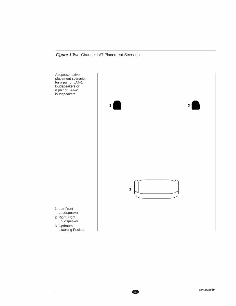
Krell encourages you to experiment and find the loudspeaker placement that reflectsyour personal preference. A LAT loudspeaker is simple to set up and use. Itsunique solid aluminum enclosure produces a soundstage that is both deep and wide,with little or no toe-in required. Figure 1 on page 11 illustrates a representativeplacement scenario. Note the position of the loudspeakers with respect to the rearand side walls. The closer a loudspeaker is to the rear wall, the more pronouncedthe bass response. To minimize unwanted reflected sound and maximize the widthand depth of the soundstage, be careful not to set the loudspeakers too close tothe side walls.
When the loudspeakers are in position, you are ready to attach the loudspeakergrill, see page 12, and install the spikes, see page 13.3-4 people needed
(SECTION TWO: Unpacking and Placement continued)
continued �11
Figure 1 Two-Channel LAT Placement Scenario
1
3
2
1 Left Front Loudspeaker
2 Right Front Loudspeaker
3 Optimum Listening Position
A representative placement scenario for a pair of LAT–1 loudspeakers or a pair of LAT–2 loudspeakers.
12
To Attach the Loudspeaker Grill
Each LAT is equipped with a snap-on grill, which consists of the grill cord strungbetween two metal bars. To install the grill, follow these steps.
1. Lift the loudspeaker grill from the grill box, using the grill bars on each end.
2. Locate the end of the grill. On the LAT–1 and LAT–2 loudspeakers, one end of thegrill will be placed at the base of the loudspeaker; the other end will be placedat the cap. On the LAT–C loudspeaker, one end of the grill will be placed on theleft cap and the other end will be placed on the right cap.
3. Gently guide the grill locator pins into the two holes on the loudspeaker base.
4. Grasp the remaining grill bar, allowing it to rest between the thumb and forefingerof each hand.
5. Pull firmly to stretch the grill cords, until the grill locator pins align with the twoholes on the loudspeaker cap.
6. Gently guide the pins into the holes. You hear a click when the grill is in place.
NoteBe careful not to scratch the surface of the loudspeaker with the grill locator pins.
To Detach the Loudspeaker Grill
The loudspeaker grill remains in place while you play music. However, if you wish tomove the loudspeaker, first detach the loudspeaker grill.
1. Grasp the grill bar that is attached to the loudspeaker cap.
2. Gently pull the bar straight out, so that the grill locator pins slide out of theholes on the loudspeaker cap.
3. Remove the grill bar from the base of the loudspeaker.
To protect the grill, Krell recommends placing it back in the grill box until you areready to reinstall it.
NoteThe grill should be cleaned periodically to remove accumulated dust. Gently wipe the grill fromtop to bottom using a soft, dry, lint-free cloth. Do not use rubber conditioner or solvent.
(SECTION TWO: Unpacking and Placement continued)

To Install the Spikes on the LAT–1
Each LAT–1 is shipped with 4 stainless steel spikes: two rear articulating spikes(with knob) and two (one long and one short) front stationary spikes (no knob). Usethese spikes to stabilize and level the loudspeaker. These spikes are particularlyimportant for sound quality if the loudspeaker will be placed on a carpeted floor.The longer front spike is for deep-pile carpeting.
IMPORTANTDo not install spikes until the loudspeaker has been placed in the listening area.
1. Insert the rear articulating spikes (with knobs) into the holes provided on the backof the loudspeaker base.
2. Turn knobs by hand until they are secure (do not over-tighten).
3. Tilt the loudspeaker back just enough to insert the front stationary spike (no knob).
IMPORTANTTwo people are needed to safely tilt the loudspeaker to install the front stationaryspike.
4. Turn the front spike by hand until it is secure (do not over-tighten).
5. Place the bubble level on the loudspeaker cap.
6. Adjust the rear articulating spikes until the bubble indicates the loudspeaker islevel.
To Install the Foot, Leg, and Pivot Mechanism on the LAT–C
1. Bolt the socket head cap screws through the screw holes on the foot and intothe right leg.
2. Insert the shoulder screw through the right shoulder screw hole on the right legand into the pivot hole on the right cap and hand tighten.
3. Move to the left side and repeat steps 1 and 2, to install the left leg and leftshoulder screw.
4. Adjust the angle of the LAT–C and insert the locator bolt through the leg and intothe locator hole in the cap, one side at a time.
13
14
SECTIONTHREEAnatomy of a Loudspeaker
This section describes LAT features and benefits.
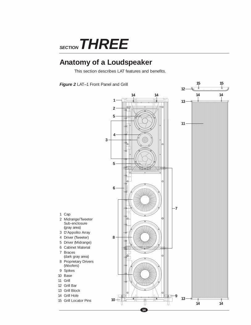
Figure 2 LAT–1 Front Panel and Grill
1
11
13
13
2
4
5
5
6
910
3
7
8
141414 14
14 14
1215 15
1 Cap2 Midrange/Tweeter
Sub-enclosure(gray area)
3 D’Appolito Array4 Driver (Tweeter)5 Driver (Midrange)6 Cabinet Material7 Braces
(dark gray area)8 Proprietary Drivers
(Woofers)9 Spikes
10 Base11 Grill12 Grill Bar13 Grill Block14 Grill Hole15 Grill Locator Pins
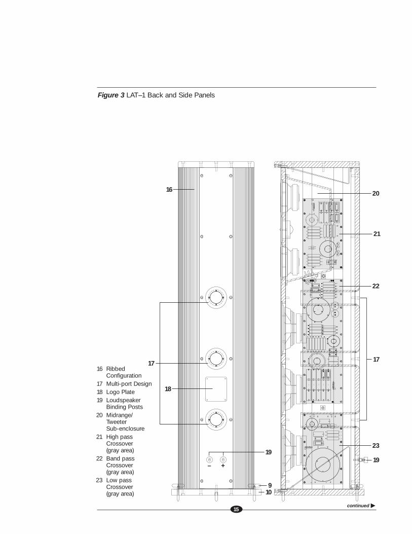
Figure 3 LAT–1 Back and Side Panels
continued �15
M20
M21
OUT -
M4
R9
M5
M6
P6
R10
C18
M10
P4
C19
R8R7
R4 R3 R2 R1
M11
M12
C20C21
C24C23C22R12R13
R14R11
OUT + P5
L2
M12M
22
M13
IN -M1
P2
M2
L1
M3
Krell industries (c) June, 2000
P25003
M13
C3C9 C7
C5
M7
C4
IN + P1
C10
C8 C6
M8
M9
C1
C15C14
C13
P3
R6R5
C2
C12
C11
C16C17
M6
M6M6
R1
R2
R3
C3
M12
R5
R4
R6
M11
M10
P8P6 P7
L2
Krell industries (c) June, 2000
M5
M4
P25001
M3
C4C5
C1
C9C8
C7 C2C6
P3M6
P5P4
P2 M8
M9
IN +M1
M2
P1
L1
IN -
OUT +OUT -
R19
R20
M22 M
12
OUT
-
P6P4
OUT
+
C29
C30
P3P5
M16
R17
R18
M18
R15
R16 M20
R12
R13
R14
C33
C32
C31C2
8
C27
L3
C26
R10
R9R1
1
M9
L1
M7
M8
M4
M4
C21
C20
C22 C2
3C2
4 C25
C16C17
C14
R8
R5
L4
R1R2R3R4R6R7
C18
C15
C19
C4C3C13
M3
P250
02
M2
IN -
C2
P2
C8
C11
C12
C10
C9C1
P1
C7C5
IN +
C6
Krel
l indu
strie
s (c
) Jun
e, 2
000
M23 M
6
M17
M19
M21
M13
M14
M12
M12
M10
M6
M15
16
18
910
1717
20
21
22
23
19+–
19
16 RibbedConfiguration
17 Multi-port Design18 Logo Plate19 Loudspeaker
Binding Posts20 Midrange/
TweeterSub-enclosure
21 High pass Crossover(gray area)
22 Band passCrossover(gray area)
23 Low pass Crossover(gray area)
16
(SECTION THREE: Anatomy of a Loudspeaker continued)
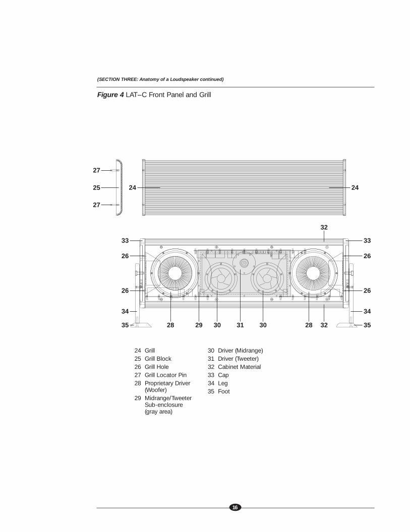
Figure 4 LAT–C Front Panel and Grill
35 28 28 32
32
29 30 30
34
26
26
24 24
33
35
34
26
26
33
27
25
27
31
24 Grill25 Grill Block26 Grill Hole27 Grill Locator Pin28 Proprietary Driver
(Woofer)29 Midrange/Tweeter
Sub-enclosure (gray area)
30 Driver (Midrange)31 Driver (Tweeter)32 Cabinet Material33 Cap34 Leg35 Foot
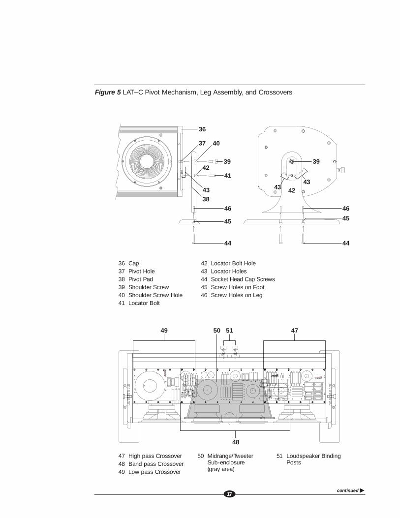
Figure 5 LAT–C Pivot Mechanism, Leg Assembly, and Crossovers
continued �17
M1 M1
M13
M13
P25003 P25003
P2P2
C10 C10
C9 C9
IN - IN -
M2 M2M3 M3
L1L1
M4 M4M5 M5
R10 R10 R9 R9
M6
M6
M6
M6
M21M21
M6 M6
OUT - OUT -P6P6
Krell industries (c) June, 2000 Krell industries (c) June, 2000
C8 C8C7 C7
C5 C5 C6 C6C2 C2
P1P1
IN + IN +
C3 C3C4 C4
C1 C1
M7 M7
R5 R5R8 R8 R7 R7
R4 R4
R6 R6
R3 R3 C11 C11
C12 C12
C16 C16
C17 C17
C13 C13
C15 C15C14 C14
R2 R2
R1 R1
L2L2
R12 R12 R13 R13 R14 R14R11 R11
C19 C19C20 C20 C18 C18
OUT + OUT +
C23 C23
C22 C22
C21 C21C24 C24
P5P5
M8 M8
P3P3P4P4
M9 M9M11 M11 M10 M10
M13
M13
M20M20M22M22
M12 M12 M12 M12
M20 M20M6M6
M23 M23
M2 M2M20 M20M6M6
M23 M23
M3 M3
P25002 P25002
M20 M20M6M6
M23 M23
M4 M4
P2P2
C8 C8C2 C2
Krell industries (c) June, 2000 Krell industries (c) June, 2000 IN - IN -
M20 M20M6M6
M23 M23
M7 M7 M4 M4M20 M20M6M6
M23 M23
M8 M8
C16C16C17 C17
C14 C14C21 C21C20 C20
L1L1
C23 C23C24 C24
C25 C25C22 C22
M20 M20M6M6
M23 M23
M9 M9
R12 R12R13 R13R14 R14
M20 M20M6M6
M23 M23
M16 M16M6M6
C33 C33
C7 C7
C6 C6
C11 C11
C12 C12
C5 C5
IN + IN +
C1 C1
P1P1
C10 C10
C9 C9
M6M6M6M6
M23 M23 M10 M10 M23 M23 M6 M6
M6M6
M23 M23 M12 M12
C18C18
C15 C15
C19 C19
C4 C4
L4L4
R1 R1
R2 R2
R3 R3
C3 C3
C13 C13
R5 R5
R4 R4
R6 R6
L3L3
M6M6
M23 M23 M13 M13 M12 M12
M6M6
M23 M23 M14 M14
M6M6
R8 R8R10 R10R11 R11 R9 R9
M23 M23 M15 M15
M6M6M6M6
M23 M23 M17 M17
R7 R7
M23 M23
M6M6M20 M20
R15 R15R16 R16
M22 M22
M12M12
R19 R19 R18 R18R20 R20 R17 R17
C32 C32
P6P6
P4P4
OUT - OUT -
C26 C26
OUT + OUT +
C29 C29C31 C31
C28 C28
C27 C27P5P5
C30 C30P3P3
M6M6
M23 M23
M6M6
M23 M23 M23 M23 M19 M19
M20 M20
M23 M23
M18 M18
M6
M6
M6
M6
P3P3
M5
M5
P4P4P5P5
OUT -
OUT -
L2L2
M4
M4
P25001P25001
M3
M3
Krell industries (c) June, 2000Krell industries (c) June, 2000
M2
M2
M1
M1
P1P1
IN +IN +
P6P6
C4C4
P7P7
OUT +
OUT +
P8P8
C3C3
R1R1
R3R3 R2R2
C1C1
C9C9C8C8
C7C7C2C2
C6C6
L1L1
M13
M13
M12
M12
R5R5
M11
M11
R4R4R6R6
M10
M10
IN -IN -
P2P2
M9
M9
M8
M8
C5C5
49 50 47
48
51
47 High pass Crossover48 Band pass Crossover49 Low pass Crossover
50 Midrange/Tweeter Sub-enclosure (gray area)
51 Loudspeaker Binding Posts
39
4243
43
36
39
41
46
45
44
46
45
44
37
43
40
42
38
36 Cap37 Pivot Hole38 Pivot Pad39 Shoulder Screw40 Shoulder Screw Hole41 Locator Bolt
42 Locator Bolt Hole43 Locator Holes44 Socket Head Cap Screws45 Screw Holes on Foot46 Screw Holes on Leg
18
(SECTION THREE: Anatomy of a Loudspeaker continued)
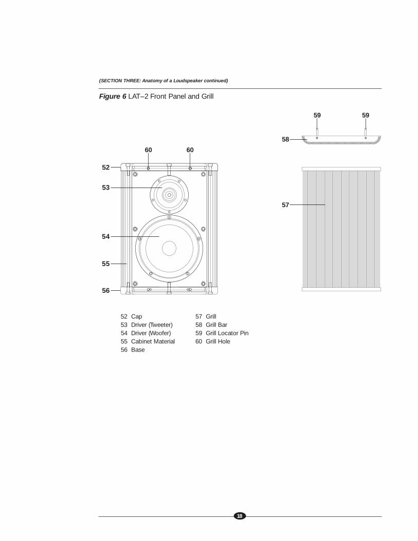
Figure 6 LAT–2 Front Panel and Grill
52 Cap53 Driver (Tweeter)54 Driver (Woofer)55 Cabinet Material56 Base
57 Grill58 Grill Bar59 Grill Locator Pin60 Grill Hole
55
52
56
53
54
57
58
60 60
59 59
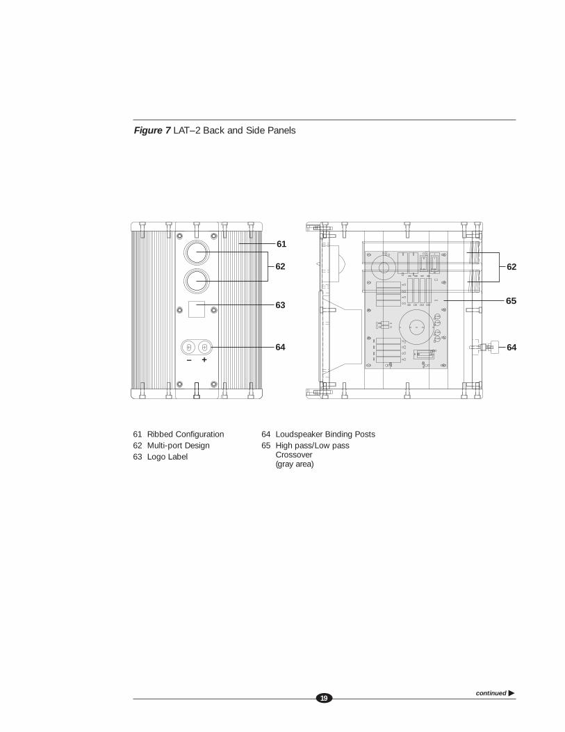
Figure 7 LAT–2 Back and Side Panels
continued �19
62
65
64+–
62
61
63
64
61 Ribbed Configuration62 Multi-port Design63 Logo Label
64 Loudspeaker Binding Posts65 High pass/Low pass
Crossover(gray area)
(SECTION THREE: Anatomy of a Loudspeaker continued)
20
Cabinet Material
The LAT sides are constructed of extruded 6063-T5 aluminum. The rigid, denserear baffle made of 6061-T6 aluminum absorbs any vibration from the driver cones.Using this heavy, inert metal means minimal vibrations—no matter how much powerthe loudspeakers handle—and thus no loss of sound.
Crossover Design
Each group of driver units (tweeter, midrange, and woofer) on the LAT–1 and LAT–Chas its own dedicated crossover circuit board. Each circuit board is made of 1/8-inchfiberglass and has a number of unique elements. To minimize parasitic inductanceand resistance, small capacitors are connected in parallel, and air-core inductorsare wound with oversize wire. In addition, each capacitor is placed in its own plasticcase, making it virtually immune to vibrations and pressure variations. This designallows each drive unit to handle its portion of the music signal without strain, maxi-mizes power delivery, and increases signal linearity while minimizing resistance andinductance. High-current polypropylene film capacitors are used exclusively in theaudio signal path.
Similarly, the resistors in the crossover networks are connected in parallel to mini-mize parasitic inductance and maximize current capacity and power dissipation.Oversized, high-power, metal oxide and wirewound resistors are used exclusively.
All the inductors are air-core types; they suffer from none of the nonlinearities at lowsignal levels and saturation at high signal levels that iron-core inductors exhibit. Allthe inductors are wound with oversize wire, reducing parasitic resistance to a fractionof an Ohm. In addition, the inductors in the midrange and tweeter filter networks arewound with Litz wire for extended high-frequency linearity.
Drivers
LAT–1 drivers are custom-built to Krell specifications. The midrange cones havefive doped cuts, providing strength without the distortion that occurs when the entirecone is doped. Woofer cones are reinforced with carbon fiber, which adds rigidityand damps cone resonance. The dual concentric tweeter features an innovativewaveguide design that increases dispersion around its axis.
21
Drivers: D’Appolito Array
In the LAT–1, a special midrange/tweeter configuration places the acoustic centerat ear level and ensures stereo imaging with pinpoint accuracy. The configurationalso provides symmetrical vertical dispersion. As a result, the listening “sweet spot”remains the same whether listeners are sitting or standing.
Loudspeaker Grill Design
The bar and cord design of the loudspeaker grill decreases reflective surfaces andthus improves sound quality. The grill design also matches the ribbed configurationof the loudspeaker body, providing a sleek, unified look.
Midrange/Tweeter Sub-Enclosure
This feature in the LAT–1 and the LAT–C separates the midrange/tweeter and woofersinto two discrete physical environments. The midrange and tweeter are enclosedin their own rigid aluminum box that separates them from the woofers, and eachunit is bolted to the back of the baffle. Standing waves are eliminated because themidrange and woofer boxes minimize parallel surfaces, and because the baffle’saluminum structure absorbs vibrations. The result is clear, distinct sound in high,mid, and low frequencies.
Multi-port Design
In the LAT–1 and LAT–2, the computer-optimized, multi-port design minimizescompression, which can cause loss of sound, especially in the bass range, athigher output levels. This design allows full excursion of drivers and the resultingdepth and range of music reproduction.
Pedestal
An optional pedestal is available for the LAT–2.
Pivot Mechanism
Multiple locator positions in the foot and leg assembly allow for optimal on-axissetup of the LAT–C center channel.
Spikes
Articulating stainless steel spikes included with the LAT–1 loudspeaker allow you tolevel the loudspeakers. The stationary front spike reduces vibrations, particularly forinstallations on carpet.
22
SECTION FOURConnecting a LAT Series Loudspeaker to Your System
To connect the loudspeaker to your system:
1. Make sure that all power sources and components are off before connectingsystem components.
2. Neatly organize wiring between all system components. Separate AC wiresfrom audio cables to prevent hum or other unwanted noise from being intro-duced into the system.
3. Locate the loudspeaker binding posts on the LAT back panel.
4. Connect the loudspeaker cable from the positive binding post on the LAT tothe positive channel output on the amplifier. Connect the loudspeaker cablefrom the negative binding post on the LAT to the negative channel output onthe amplifier.
IMPORTANTDo not disconnect signal cables when the amplifier is on and connected to theloudspeaker. Doing so will cause a loud pop that may damage your components.
Tighten loudspeaker binding posts by hand only.
continued �23
SECTION FIVEKrell HEAT: Home Theater Technology
The Krell Lossless Acoustic Transducer (LAT) loudspeakers are part of a whole familyof loudspeakers newly designed by Krell. The LAT–C and the LAT–2 are voiced pre-cisely for use with the LAT–1. Together with the Krell Master Reference Subwoofer,these components comprise the High-End Audio Theater (HEAT) loudspeaker,continuing the Krell tradition of making the best high-performance audio technologyavailable for home theater.
Today’s home theater soundtracks contain a demanding range of dynamic material,from the softest music or whispered conversation to the roar of a jet take-off.The soundtrack plays a key role in the action seen on the screen and its contentis becoming increasingly complex with each theatrical release. LAT loudspeakersaddress the demands of these soundtracks in three ways: superior power handling,ultra-fast response, and high resolution at low levels.
Krell HEAT provides an electronic transcription of the source material from DVDto amplifier output. The LAT provides the mechanical transcription—faithfullyand without coloration—from loudspeaker input to listener. These loudspeakers,driven by Krell amplifiers, guarantee that you will experience the soundtrack ofany film just as the director intended.
See Figure 8, on page 24, for a home theater placement scenario using KrellLossless Acoustic Transducers.

24
Figure 8 A Krell HEAT (Home Theater) System Placement Scenario
(SECTION FIVE: Krell HEAT: Home Theater Technology continued)
1
8
2
5
6 7
3
4
1 Left Front Loudspeaker (LAT–1)
2 Right Front Loudspeaker (LAT–1)
3 Master Reference Subwoofer
4 Center Loudspeaker (LAT– C)
5 Screen6 Left Rear
Loudspeaker (LAT–2)7 Right Rear
Loudspeaker (LAT–2)8 Optimum
Listening Position
continued �25
WarrantyEach LAT Series loudspeaker has a limited warranty of five years for parts and labor.Should this product fail to perform at any time during the warranty, Krell will repairit at no cost to the owner, except as set forth in this warranty.
This warranty does not apply to damage caused by acts of God or nature.
The warranty described on this page shall be in lieu of any other warranty, expressedor implied, including, but not limited to, any implied warranty of merchantability orfitness for a particular purpose. There are no warranties which exceed beyondthose described in this document. If this product does not perform as warrantedherein, the owner’s sole remedy shall be repair. In no event will Krell be liable forincidental or consequential damages arising from purchase, use, or inability to usethis product, even if Krell has been advised of the possibility of such damages.
Proof of purchase in the form of a bill of sale or receipted invoice substantiatingthat the unit is within the warranty period must be presented to obtain warrantyservice. The warranty begins on the date of the original retail purchase, as notedon the bill of sale or receipted invoice from an authorized Krell dealer or distribu-tor. Previously owned equipment, when re-purchased from an authorized Krelldealer or distributor, has the balance of the original warranty, based on the origi-nal date of manufacture.
The warranty for Krell products is valid only in the country to which they wereoriginally shipped, through the authorized Krell distributor for that country, and atthe factory. There may be restrictions on or changes to Krell’s warranty becauseof regulations within a specific country. Please check with your distributor for acomplete understanding of the warranty in your country.
If a unit is serviced by a distributor who did not import the unit, there may be acharge for service, even if the product is within the warranty period.
Freight to the factory is your responsibility. Return freight within the United States(U.S.A.) is included in the warranty. If you have purchased your Krell product outsidethe U.S.A. and wish to have it serviced at the factory, all freight and associatedcharges to the factory are your responsibility.
26
Krell will pay return freight to the U.S.A.-based freight forwarder of your choice.Freight and other charges to ship the unit from the freight forwarder to you are alsoyour responsibility.
Krell is not responsible for any damage incurred in transit. Krell will file claimsfor damages as necessary for units damaged in transit to the factory. You areresponsible for filing claims for shipping damages during the return shipment.
Krell does not supply replacement parts and/or products to the owner of the unit.Replacement parts and/or products will be furnished only to the distributor perform-ing service on this unit on an exchange basis only; any parts and/or productsreturned to Krell for exchange become the property of Krell.
No expressed or implied warranty is made for any Krell product damaged byaccident, abuse, misuse, natural or personal disaster, or unauthorized modification.
Any disassembly, component replacement, perforation of chassis, updates,or modifications performed to the unit will void the warranty.
In the event that Krell receives a product for warranty service that has been modifiedin any way without Krell authorization, all warranties on that product will be void.The product will be returned to original factory layout specifications at the owner’sexpense before it is repaired. All repairs required after the product has been returnedto original factory specifications will be charged to the customer, at current partsand labor rates.
All operational features, functions, specifications, and policies are subject to changewithout notification.
(WARRANTY continued)
To register your product for warranty benefits, please complete and returnthe Warranty Registration Card enclosed in the shipping box within 15 daysof purchase. Thank you.
Return Authorization ProcedureIf you believe there is a problem with your component, please contact your dealer,distributor, or the Krell factory to discuss the problem before you return the componentfor repair. To expedite service, you may wish to complete and e-mail the ServiceRequest Form in the Service Section of our website at:
http://www.krellonline.com
To return a product to Krell, please follow this procedure so that we mayserve you better.
1. Obtain a Return Authorization Number (R/A number) and shipping address fromthe Krell Service Department.
2. Insure and accept all liability for loss or damage to the product during shipmentto the Krell factory and ensure all freight (shipping) charges are prepaid.
The product may also be hand delivered if arrangements with the Service Departmenthave been made in advance. Proof of purchase will be required for warranty validationat the time of hand delivery.
IMPORTANTUse the original packaging to ensure the safe transit of the product to the factory,dealer, or distributor. Krell may, at its discretion, return a product in new packagingand bill the owner for such packaging if the product received by Krell was boxed innonstandard packaging or if the original packaging was so damaged that it wasunusable. If Krell determines that new packaging is required, the owner will benotified before the product is returned.
To purchase additional packaging, please contact your authorized Krell dealer,distributor, or the Krell Service Department for assistance.
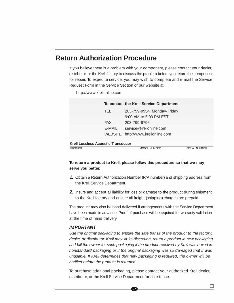
To contact the Krell Service Department
TEL 203-799-9954, Monday-Friday9:00 AM to 5:00 PM EST
FAX 203-799-9796E-MAIL [email protected] http://www.krellonline.com
Krell Lossless Acoustic TransducerPRODUCT MODEL NUMBER SERIAL NUMBER
27

KRELL INDUSTRIES, INC.45 CONNAIR ROAD
ORANGE, CT 06477-3650 USA