IPCAM User's Manual - Wision · IPCAM User's Manual 4 Safety Instructions Please ensure that users...
44
IPCAM User's Manual V 3.0.28 © Copyright Copyright Copyright Copyright 8 th th th th Dec. Dec. Dec. Dec. 201 201 201 2011 This manual contains proprietary information, protected by copyright. All rights reserved.
-
Upload
vuongkhuong -
Category
Documents
-
view
233 -
download
3
Transcript of IPCAM User's Manual - Wision · IPCAM User's Manual 4 Safety Instructions Please ensure that users...

IPCAM User's Manual
V 3.0.28
©©©© CopyrightCopyrightCopyrightCopyright 8888thththth Dec.Dec.Dec.Dec. 2012012012011111
This manual contains proprietary information, protected by copyright. All rights reserved.

IPCAM User's Manual
2
ContentsContentsContentsContents
Contents.................................................................................................................................................2Safety Instructions................................................................................................................................. 4Ⅰ Product Features..............................................................................................................................6Ⅱ Product Application..........................................................................................................................6Ⅲ Product Description......................................................................................................................... 9
3.1 Product Appearance Structure Description.................................................................................................. 93.2 Back Board Description............................................................................................................................... 103.3 Alarm I/O Wiring Description......................................................................................................................113.4 Installation Description............................................................................................................................... 12
Ⅳ Network Connections Topology Type............................................................................................134.1 Topology Type 1.......................................................................................................................................... 134.2 Topology Type2........................................................................................................................................... 134.3 Topology Type3........................................................................................................................................... 13
Ⅴ Client Software Installation and Instruction..................................................................................14Ⅵ Web Client Navigation................................................................................................................... 14
6.1 System Requirements..................................................................................................................................146.2 Connection Access HD IP Camera................................................................................................................146.3 Web Client Function Navigation..................................................................................................................18
Ⅶ Web Client Operation Details........................................................................................................ 207.1 Live Video.................................................................................................................................................... 207.2 Image Setting...............................................................................................................................................21
7.2.1 Basic Parameter...............................................................................................................................217.2.2 Advanced Parameter.......................................................................................................................217.2.3 Lens parameters setting..................................................................................................................23
7.3 Network Setting...........................................................................................................................................237.4 System Date.................................................................................................................................................24
7.4.1 Camera Time................................................................................................................................... 247.4.2 OSD Setting......................................................................................................................................257.4.3 Audio Setting...................................................................................................................................267.4.4 Account Management.....................................................................................................................267.4.5 Software Upgrade........................................................................................................................... 287.4.6 System Logs.....................................................................................................................................28
7.5 Application...................................................................................................................................................297.5.1 SD Card............................................................................................................................................297.5.2 Scheduled Record............................................................................................................................30
7.6 Alarm Setting...............................................................................................................................................317.6.1 IO Alarm...........................................................................................................................................317.6.2 Face Detection.................................................................................................................................317.6.3 Motion Detection............................................................................................................................327.6.4 Network off Alarm...........................................................................................................................33
7.7 Storage Management..................................................................................................................................33

IPCAM User's Manual
3
7.7.1 Local Storage................................................................................................................................... 337.7.2 Snapshot Settings............................................................................................................................347.7.3 SDcard Files Management...............................................................................................................357.7.4 Local Video Management................................................................................................................36
7.8 Lens and PTZ Control...................................................................................................................................377.8.1 Lens Control.....................................................................................................................................377.8.2 PTZ Control......................................................................................................................................38
Ⅷ WAN Access....................................................................................................................................388.1 WAN Access HD IP CAM with Fixed Static IP...............................................................................................388.2 WAN Access HD IP CAM without Fixed Static IP......................................................................................... 39
Ⅸ FAQ.................................................................................................................................................41Appendix 1: Reticle Making................................................................................................................. 42Appendix 2: Technical Parameter........................................................................................................43
IPCAM User's Manual
4
Safety Instructions
Please ensure that users read these safety instructions carefully before using the product to avoid dangers or
property losses and keep in save for future reference.
GraphicGraphicGraphicGraphic SymbolSymbolSymbolSymbol DDDDesignationesignationesignationesignation NoticeNoticeNoticeNotice
WARNINGWARNINGWARNINGWARNING IgnoreIgnoreIgnoreIgnore thisthisthisthis WarningWarningWarningWarning mightmightmightmight causecausecausecause thethethethe deathdeathdeathdeath orororor injuryinjuryinjuryinjury....
NOTICENOTICENOTICENOTICE IgnoreIgnoreIgnoreIgnore thisthisthisthis AttentionAttentionAttentionAttention mightmightmightmight causecausecausecause harmharmharmharm orororor propertypropertypropertyproperty losses.losses.losses.losses.
WARNINGWARNINGWARNINGWARNING
1. Power requirements need to satisfy SELV (safety extra low voltage).
2. If the equipment work abnormal, please contact the store of purchase or the nearest service center, please do
not remove or modify the equipment in any way.(Any unauthorized modification or maintenance of problems,
responsibilities conceited)
3. To reduce the risk of fire or shock, Please do not let this product by rain or damp.
4. The installation should be conducted by professional service, and the regulations.
5. The power-off facility should build in the assembly line.
6. The ceiling installation instructions: After installation, please ensure that the connection can bear at least 50
newton (N) downward of pulling.

IPCAM User's Manual
5
NOTICENOTICENOTICENOTICE
1. Before running IP CAM, please examine the power supply.
2. Avoid falling or strong percussion.
3. To clean the camera, please use blower remove dust from Lens or Filter; to clean IP CAM outside
surface with soft, dry cloth. For stubborn splodge, please use soft cloth with a little cleanser to clean, and
then dry after. Please do not use volatile solvent, e.g., alcohol, benzene, diluents, etc., avoid the damage
of face coat.
4. The camera should not be mounted in such wet, dusty, hot, icy (Operating Temp: -10℃~+50℃)
places, strong electromagnetic radiation or near to any high-intensity magnetic fields.
5. Avoid heat savings and keep ventilating nearby IPCAM.
6. Please do not let any water or liquid inflow the IPCAM.
7. Please re-packaging product as to the factory package for transporting, or the same quality of
materials for packaging.
8. According to average life of some parts of the IP CAM (e.g. electrolytic capacitor) need to renew
regularly. Parts life is based on the use of service environment and service time. Recommend inspection
of IP CAM regularly. For more details please contact dealer.
9. The manufacturer specified accessories and parts are recommended only.
10. If the device damaged, such as power line, plug damaged, liquid inflow, bodies falling into the device,
get wet in the rain, be affected with damp and falling cause any abnormal running, please contact dealer
or maintenance service center ASAP.
11. Please do not dismantle IPCAM and bolt or case to prevent electric shock. There are no parts in this IP
CAM can be repaired by users.
12. Any maintenance work should be conducted by professional service.
13. Please keep this user manual for future references. If lose, please contact customer service to re-obtain
the user manual.

IPCAM User's Manual
6
Ⅰ ProductProductProductProduct FeaturesFeaturesFeaturesFeatures
This series is the embedded digital monitoring equipment which centralizes high resolution analog camera and
network video server in one body. Adopt the embedded Linux operating system and TI’s newest Davinci
Hardware platform, efficient system operation, Code curing in Flash, small volume, with high standard stability
and reliability.
Product main features:
1. Built-in WEB Server, support IE Brower;
2. H.264/MPEG4/M-JPEG Video coding arithmetic, Image more smooth and clear;
3. G.711/G.726/AMR audio coding, external microphone and loudspeaker, support voice communication;
4. 10BaseT/100BaseTX Ethernet and 802.11b/g WLAN port (-W Model Support);
5. Support built-in Micro SD card, achieve local short time storage.
6. Integrated network storage protocols, Support Network Hard disk functions;
7. Flexible access to infrared, door magnetic, alarm smoke detectors, etc;
8. Support arming, disarming operation;
9. Support for motion detection, intelligent analysis capabilities, to trigger video recording and alarm functions
as needed;
10. Rich Network protocol ,Support
IPv4/IPv6,HTTP,TCP,ICMP,RTSP,RTP,UDP,IGMP,RTCP,SMTP,FTP,DHCP,DNS,DDNS,UPNP, etc
11. Support remote configuration, remote upgrade, fault detection, auto detection and remote maintenance
function, etc;
12. An open standard API Interface, support SDK integration develop, facilitate the development of various
applications;
Notice:Notice:Notice:Notice: Some features require a specific model support.
Ⅱ ProductProductProductProduct ApplicationApplicationApplicationApplication
Network Video can use for almost any application. But most mainly used on people, places, property and
operations for security monitoring or remote monitoring. Whether you need IP monitoring solution to ensure the
safety of people and places, or remote monitoring of security of property and facilities, this series of HD IP CAM

IPCAM User's Manual
7
can satisfy all your requirements. The IP CAM will be well applied in such retail, education, traffic, industry, City
Fitness, finance, government, health care, etc.
This series of HD IP CAM with exceptional image quality: can clearly capture the process of incident and
identify the characters and objectives involved in the process. Depend on the progressive scan technology and
megapixels, This series of HD IP CAM can provide superior image quality and higher resolution, which is
unmatched by simulative CCTV cameras; this series of HD IP CAM and Video Encoder has built-in with video
motion detection, audio detection alarm, active anti-demolition alarm I/O connections and also alarm and event
management functions. These features make HD IP CAM and video encoder be capable of continuous analysis of
the information Enter, incident detection, automatic video recording and alarm notification. Rich peripheral
interface of this series of HD IP CAM can easily access a variety of alarm equipments.
FigureFigureFigureFigure 1111 EquipmentEquipmentEquipmentEquipment ConnectingConnectingConnectingConnecting
In addition, this HD IP CAM could build network easily, which support LAN, WIFI, 3G module and other
access methods, as well as mobile phones and computers. The figure of the system network diagram shows below:

IPCAM User's Manual
8
FigureFigureFigureFigure 2222 SystemSystemSystemSystem NetworkingNetworkingNetworkingNetworking
NOTICENOTICENOTICENOTICE
Set up and operate HD IP CAM after connecting device. (As per Figure 2)
Please note the followings:
� Please check your package contents to ensure that all items have been included.
� Please read this part carefully before installing: ensure that power off.
Related equipment: check power supply voltage avoids device damage.
� Installation Environment: please do not use product in such exceed standard damp or high
Temperature environments keep good ventilation and prevent the rain.
� Avoid installing in the severe vibration environment.
� Camera has no power switch.
� A long operation in the high temperature and humidity conditions will lead to component
Damage
� Do not install the IP CAM in the place near the radiator, heater, etc.
� Avoid camera operate in place with a lot of steam and oil
� CMOS filter aging: keep CMOS filter concentrating at one point for a long time under glare will
cause the reduction of its quality. The affected part will change color. There is discoloration in
image after removing the camera’s location.
� Please do not clean the camera body with strong or abrasive cleaning agent. Switch off the camera
Before cleaning and wipe the camera with soft cloth. If stubborn splodge can not be removed, please
dilute splodge with water and remove with neutral cleanser. Dry cloths before wipe and be careful
do not scratch the ball cover.

IPCAM User's Manual
9
� Do not make the camera aim at the sun. Ensure that camera is not aim at the sun or other extreme
Bright objects whether the camera is in use or non-use. Otherwise it may cause image blurring or
produce Halo.
� Do not leave the camera toward at strong light sources for long. Spotlight or strong light sources
may cause the aging of screen. Keep IP CAM toward to a strong light sources for long and the
damage of CMOS color filters will cause the color lose of images.
● Please contact the dealer or the nearest customer service center if the equipment working abnormal.
Do not remove or modify the equipment in any way. (Any unauthorized modification or
maintenance of problems, responsibilities conceited)
� HD IP CAM package includes an optional power supply, Lens and SD Card.
� C Lens (<1kg): use C assemble commutator; C/S Lens: no installation require.
Ⅲ ProductProductProductProduct DescriptionDescriptionDescriptionDescription
3.13.13.13.1 ProductProductProductProduct AppearanceAppearanceAppearanceAppearance StructureStructureStructureStructure DescriptionDescriptionDescriptionDescription
Figure 3 HD IPCAM 3651.Camera mounting hole; 2. Aluminum Ring;3. Aluminum Ring Screw
1. Camera mounting hole: to fix camera on the mounting bracket, which is convenient for mounting.
2. Aluminum ring: used to adjust the distance between lens and CMOS inductor. When the image is not
clear by using ring tone then adjust the focal length of the aluminum ring.

IPCAM User's Manual
10
3. Aluminum ring screws: for aluminum ring fixing (Figure 3), loosen the screws with a screwdriver if it
needs to adjust the location of aluminum ring
3.23.23.23.2 BackBackBackBack BoardBoardBoardBoard DescriptionDescriptionDescriptionDescription
1 8
2
3
5 6
7
4
FigureFigureFigureFigure 2222 BackBackBackBack BoardBoardBoardBoard
NO.NO.NO.NO. DDDDesignationesignationesignationesignation DescriptionDescriptionDescriptionDescription
1111 485485485485 andandandand AlarmAlarmAlarmAlarm InterfaceInterfaceInterfaceInterface RS485 Interface is Connected to PTZ Control:
� RS485 Interface: DP/DN, Indicate RS485 the (P) Positive and
( N ) Negative of Interface
� 2 Channel Switch Value Enter: IN1/GND/IN2/GND, Indicate
Two Channel Switching Input
� 1 Channel Switch Value Output: NO/COM,NO/COM is the
Switching Value Output of the Normally Closed Contact Point
2222 DDDDCCCC 12V12V12V12V 12V DC Power Supply Input Terminal
3333 RESETRESETRESETRESET ButtonButtonButtonButton To Restore factory Default Settings. When equipment working
under abnormal conditions (Operation Indicator Light), Press and
Hold the button 3s, then switch off, Re-Plug the power supply. The
System Automatically Reset System Configuration Information
back to the Default Values.
IPCAM User's Manual
11
4444 MIN-USBMIN-USBMIN-USBMIN-USB AuxiliaryAuxiliaryAuxiliaryAuxiliary
InterfaceInterfaceInterfaceInterface
USB/RS232/AVOUT Interface:
� USB: Connect to PC for DHCP Settings
� RS232: Debug Serial Port, Debugging for Technical staff to
Upgrade
AVOUT: Audio Video Output
5555 SD-CARDSD-CARDSD-CARDSD-CARD Insert SD Card here
6666 AUTO-IRISAUTO-IRISAUTO-IRISAUTO-IRIS AdjustmentAdjustmentAdjustmentAdjustment Connect the lens aperture with control line
7777 SYSSYSSYSSYSOperationOperationOperationOperation IIIIndicatorndicatorndicatorndicator Indicates DVR System Running Status; Normal Status:
Normal Status: Indicator Light goes off every 1s.
Abnormal Status: Indicator Light goes off every 3s
8888 LANLANLANLAN NINININI 10/100M NI
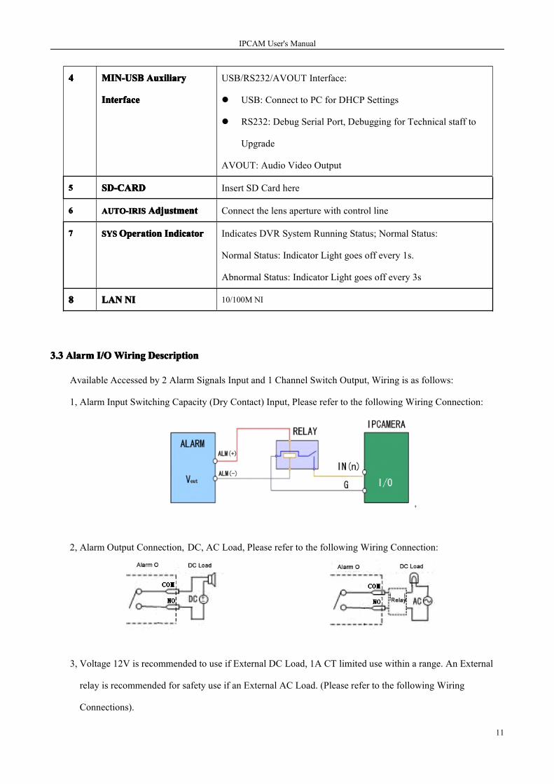
3.33.33.33.3 AlarmAlarmAlarmAlarm I/OI/OI/OI/OWiringWiringWiringWiring DescriptionDescriptionDescriptionDescription
Available Accessed by 2 Alarm Signals Input and 1 Channel Switch Output, Wiring is as follows:
1, Alarm Input Switching Capacity (Dry Contact) Input, Please refer to the following Wiring Connection:
2, Alarm Output Connection, DC, AC Load, Please refer to the following Wiring Connection:
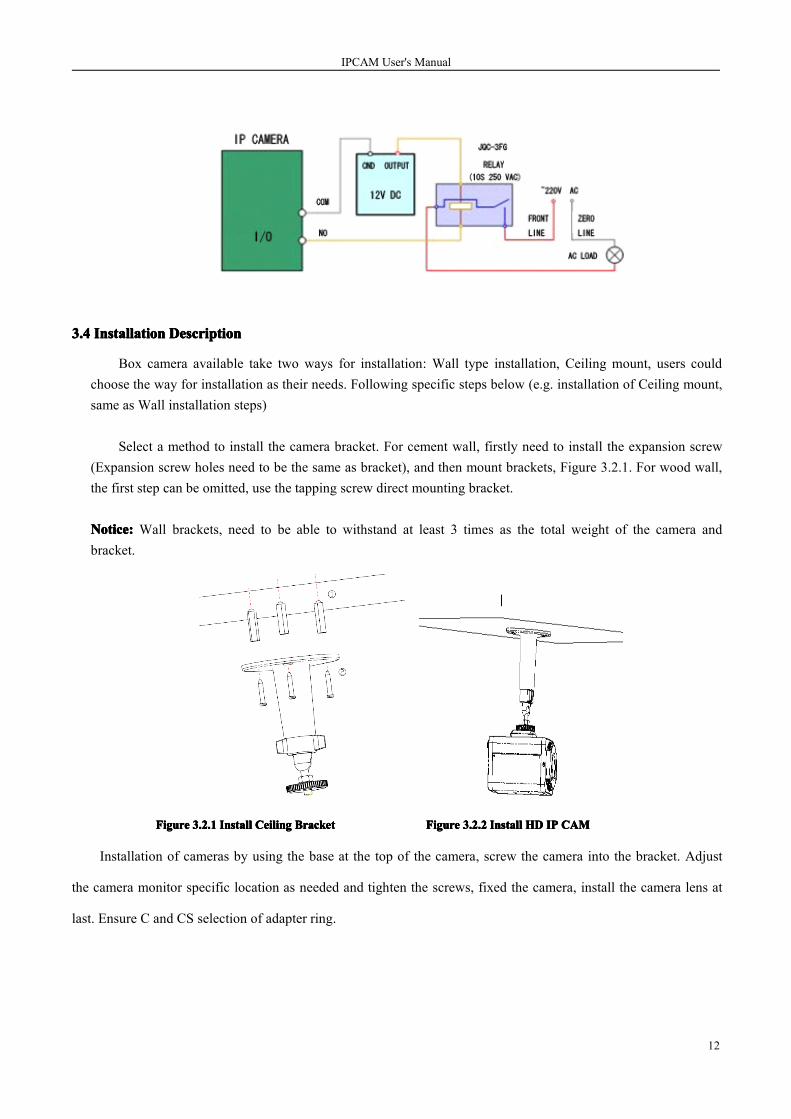
3, Voltage 12V is recommended to use if External DC Load, 1A CT limited use within a range. An External
relay is recommended for safety use if an External AC Load. (Please refer to the following Wiring
Connections).
IPCAM User's Manual
12
3.43.43.43.4 InstallationInstallationInstallationInstallation DescriptionDescriptionDescriptionDescription
Box camera available take two ways for installation: Wall type installation, Ceiling mount, users couldchoose the way for installation as their needs. Following specific steps below (e.g. installation of Ceiling mount,same as Wall installation steps)
Select a method to install the camera bracket. For cement wall, firstly need to install the expansion screw(Expansion screw holes need to be the same as bracket), and then mount brackets, Figure 3.2.1. For wood wall,the first step can be omitted, use the tapping screw direct mounting bracket.
Notice:Notice:Notice:Notice: Wall brackets, need to be able to withstand at least 3 times as the total weight of the camera andbracket.
FigureFigureFigureFigure 3.2.13.2.13.2.13.2.1 InstallInstallInstallInstall CeilingCeilingCeilingCeiling BracketBracketBracketBracket FigureFigureFigureFigure 3.2.23.2.23.2.23.2.2 InstallInstallInstallInstall HDHDHDHD IPIPIPIP CAMCAMCAMCAM
Installation of cameras by using the base at the top of the camera, screw the camera into the bracket. Adjust
the camera monitor specific location as needed and tighten the screws, fixed the camera, install the camera lens at
last. Ensure C and CS selection of adapter ring.
IPCAM User's Manual
13
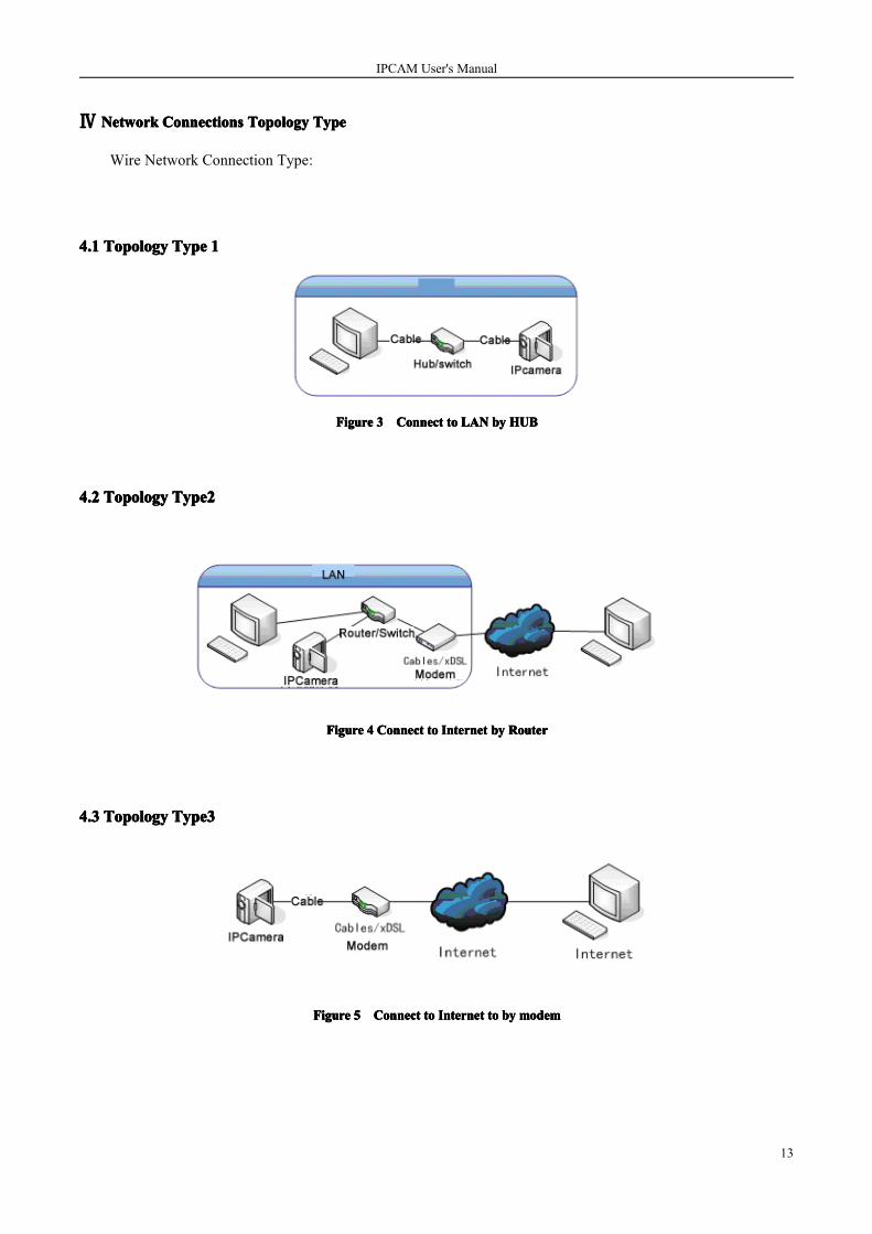
Ⅳ NetworkNetworkNetworkNetwork ConnectionsConnectionsConnectionsConnections TopologyTopologyTopologyTopology TypeTypeTypeType
Wire Network Connection Type:
4.14.14.14.1 TopologyTopologyTopologyTopology TypeTypeTypeType 1111
FigureFigureFigureFigure 3333 ConnectConnectConnectConnect totototo LANLANLANLAN bybybyby HUBHUBHUBHUB
4.24.24.24.2 TopologyTopologyTopologyTopology Type2Type2Type2Type2
FigureFigureFigureFigure 4444 ConnectConnectConnectConnect totototo InternetInternetInternetInternet bybybyby RouterRouterRouterRouter
4.34.34.34.3 TopologyTopologyTopologyTopology Type3Type3Type3Type3
FigureFigureFigureFigure 5555 ConnectConnectConnectConnect totototo InternetInternetInternetInternet totototo bybybyby modemmodemmodemmodem

IPCAM User's Manual
14
Ⅴ ClientClientClientClient SoftwareSoftwareSoftwareSoftware InstallationInstallationInstallationInstallation andandandand InstructiInstructiInstructiInstructionononon....
Refer to IPCAM Network Video Monitoring Software User’s Manual.
ⅥWebWebWebWeb ClientClientClientClient NavigationNavigationNavigationNavigation
6.16.16.16.1 SystemSystemSystemSystemRequirementsRequirementsRequirementsRequirements
To enable HD IP CAM running normally, computer needs to meet the following configuration requirements:
1. Processor Pentium IV 2GHz or above
2. RAM 1G or above
3. Resolution Ratio 1280 × 720 + / 32-bit Color or higher / 128M Independent video memory or above
4. IE Brower (IE Explorer) 6.0 or above
5. DirectX 9.0 or above
6. TCP/IP protocols.
6.26.26.26.2 ConnectionConnectionConnectionConnection AccessAccessAccessAccess HDHDHDHD IPIPIPIP CameraCameraCameraCamera
Notice: In turn connect the Cameras, DVS with PC, ensure route and power supply are working normal
1. Each HD IP CAM factory default IP address:192.168.1.253192.168.1.253192.168.1.253192.168.1.253, net mask: 255.255.255.0255.255.255.0255.255.255.0255.255.255.0
Notice: access to HD IP CAM, PC IP must be in the same segment as HD IP CAM and net mask is same. e.g.:
IP address is 192.168.1.253, the current IP address of the PC can be 192.168.1.202. Modify the parameters of the
PC IP address showing as below:

IPCAM User's Manual
15

IPCAM User's Manual
16
2. Testing HD IP CAM activate normally. WINDOWS click Start —> Operate —>Enter “cmdcmdcmdcmd”—>Enter
3. Open a command window, enter “pingpingpingping 192.168.1.253192.168.1.253192.168.1.253192.168.1.253”, Enter. showing as below:

IPCAM User's Manual
17
4. For the first time, use Microsoft Internet Brower access to the device must temporarily reduce Security
Settings of IE Brower to install “ActiveX Controls and Components” into the system. Open Tool
Menu—>Internet Options—>Security—> Custom Level—>ActiveX Controls and Plug-in, change “Disable”
to “Enable”.
5. Set the security level “low” and click Apply, then open Microsoft Internet Brower, follow Below steps to
connect to the Device:
1) Select the IE Address Bar;
2) Enter the IP Address into the Address Bar;
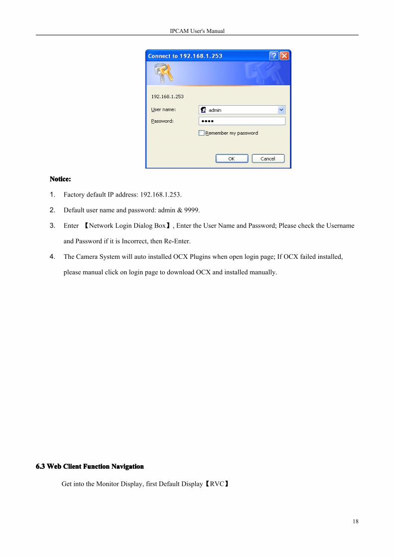
3) 【Network Login Dialog Box】Enter the User Name and Password (User Name => adminadminadminadmin,,,,
Password => 9999999999999999) click OK/Confirm;
4) If the User Name and Password are Correct, then access to the Monitoring Display Screen.
IPCAM User's Manual
18
Notice:Notice:Notice:Notice:
1. Factory default IP address: 192.168.1.253.
2. Default user name and password: admin & 9999.
3. Enter 【Network Login Dialog Box】, Enter the User Name and Password; Please check the Username
and Password if it is Incorrect, then Re-Enter.
4. The Camera System will auto installed OCX Plugins when open login page; If OCX failed installed,
please manual click on login page to download OCX and installed manually.
6.36.36.36.3 WebWebWebWeb ClientClientClientClient FunctionFunctionFunctionFunction NavigationNavigationNavigationNavigation
Get into the Monitor Display, first Default Display【RVC】

IPCAM User's Manual
19
WebWebWebWeb Client Navigation Menu
Chapter NO. & Main Menu Sub-chapter NO. & Sub-menu Notice
7.1 Live Video Detailed setting, see Part VII
of the section description
7.2 Image Setting 7.2.1 Basic Parameter Detailed setting, see Part VII
of the section description7.2.2 Advanced Parameter
7.2.3 Lens parameters setting
7.3 Network Setting 7.3.1 Wired Network Parameter Detailed setting, see Part VII
of the section description
7.4 System Setting 7.4.1 System Date Detailed setting, see Part VII
of the section description7.4.2 OSD
7.4.3 Audio Setting
7.4.4 Account Management
7.4.5 Software Upgrade
7.4.6 System Log
7.5 Application 7.5.1 SD Card Application Detailed setting, see Part VII
of the section description7.5.2 Timer Video Recording
7.5.3 Enable Record
7.5.4 Scheduled Record
7.5.5 Alarm
7.5.6 Motion Detection
7.6 Alarm Setting 7.6.1 I/O Alarm Detailed settings, see Part VII
of the section description7.6.2 Face Detection
7.6.3 Motion Detection
7.6.4 Network off Alarm
7.7 Storage Management 7.7.1 Local Storage Setting Detailed settings, see Part VIIof the section description7.7.2 Snapshot settings
7.7.3 SD Card Files Management7.7.4 Local Video Management
7.8 PTZ Control 7.8.1 Lens Control Detailed settings, see Part VII

IPCAM User's Manual
20
of the section description7.8.2 PTZ Control
ⅦWebWebWebWeb ClientClientClientClient OperationOperationOperationOperation DetailsDetailsDetailsDetails
7.17.17.17.1 LiveLiveLiveLive VideoVideoVideoVideo
� Login the camera.
System menu and toolbar are described below:
� By using to choose different resolution
� This button Switch On/Off current live video
� Available to capture the current preview coded format and corresponding resolution video
� Start / Stop Video record for current coded format and corresponding resolution
� Enter into the Playback page, Search Video Files and playback
� Open Remote Audio Monitoring Function
� To obtain the Alarm Information
� Switch to full screen

IPCAM User's Manual
21
7.27.27.27.2 ImageImageImageImage SettingSettingSettingSetting
7.2.17.2.17.2.17.2.1 BasicBasicBasicBasic ParameterParameterParameterParameter
� Please follow the steps below to adjust the image parameter as needed
1. Click on BasicBasicBasicBasic ParameterParameterParameterParameter button to enter into the Basic Parameter Setting Menu
2. Available to set follows: Day /Night Switch; Binning Mode; BLC; Backlight; Illumination; Contrast;
Saturation; Sharpness, etc. Click Default to reset
3. Click LiveLiveLiveLive VideoVideoVideoVideo button back to the main menu preview updated Image/Video
Basic Parameter Button Description:
● Brightness: Available setting Brightness value between (0~255)
● Contrast: Available setting Contrast value between (0~255)
● Saturation: Available setting Saturation value between (0~255)
● Acuteness: Available setting Sharpness value between (0~255)
● Submit: Click transfer new setting value to IPCAM
● Default: Click to set the value back to default value
7.2.7.2.7.2.7.2.2222 AdvancedAdvancedAdvancedAdvanced ParameterParameterParameterParameter
� Please follow the steps below to adjust the image parameter from the network as needed

IPCAM User's Manual
22
1. Click on Image setting button and choose Advanced Parameter to enter into the Advanced Parameter
Setting Menu
2. Available setting follows from Image Parameter Setting Menu: Streams, Encode Mode, Exposure mode,
video standard, Mirror image, Code Rate Control, Bit Rate, Frame Rate, Camera Name.
3. Click Submit to complete your setting
Image Parameter button function description:
● CameraCameraCameraCamera Name:Name:Name:Name: Enter IPC name
● WhiteWhiteWhiteWhite Balance:Balance:Balance:Balance:White Balance mode Setting
● MirrorMirrorMirrorMirror Image:Image:Image:Image: Image setting up, down , letf and right reverse direction.
● VideoVideoVideoVideo standard:standard:standard:standard: NTSC/PAL
● FlickerFlickerFlickerFlicker:::: Flicker function activated and turned on....
● ExposureExposureExposureExposure Mode:Mode:Mode:Mode: Setting Exposure Mode , as Flicker function off. Increase the exposure time and Max Gain as
Otherwise, reduce.
● StreamsStreamsStreamsStreams ::::Max support triple
● EncodEncodEncodEncodeeee ModeModeModeMode:::: Support two group encode mode.
● Resolution:Resolution:Resolution:Resolution: Select Display resolution from here, the drop-list will display the corresponding mode for you to
select, e.g. Video Coding mode- Dual H.264, include H.264:720, H.264: CIF, & H.264 VGA, H.264:CIF.
● CodeCodeCodeCode RateRateRateRate Control:Control:Control:Control: Client provide two Code Rate Control Mode, VBR (auto code rate control), and CBR (fix
code rate control),
IPCAM User's Manual
23
● ImageImageImageImage Quality:Quality:Quality:Quality: JPEG Image quality selection: “high, medium, low”
● FrameFrameFrameFrame Rate:Rate:Rate:Rate:Different Coding Mode and Resolution available select from corresponding option,
30FPS”,“15FPS”, “7.5FPS” “3FPS” or “1FPS”, etc. (Note: H.264:1080 max 10fps, MPEG4:1080P max 24fps,
and other mode frame rate up to 30fps)
● CodeCodeCodeCode Rate:Rate:Rate:Rate: Available setting to different format video code rate, setting range between 64-12000
● Submit:Submit:Submit:Submit: Click transfer new setting value to IPCAM
● Default:Default:Default:Default: Click to set the value back to default value
Note:Note:Note:Note: After submit your setting the screen will Display Loading… please wait until Image auto display on the
screen
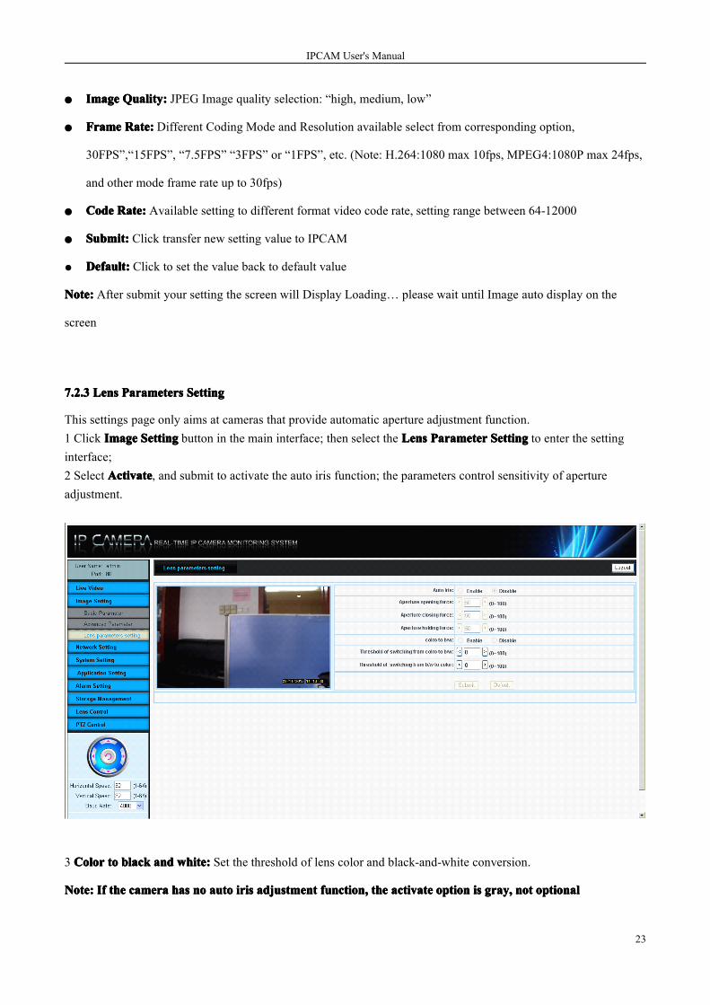
7.2.7.2.7.2.7.2.3333 LensLensLensLens ParametersParametersParametersParameters SettingSettingSettingSetting
This settings page only aims at cameras that provide automatic aperture adjustment function.1 Click IIIImagemagemagemage SSSSettingettingettingetting button in the main interface; then select the LLLLensensensens PPPParameterarameterarameterarameter SSSSettingettingettingetting to enter the settinginterface;2 Select AAAActivatectivatectivatectivate, and submit to activate the auto iris function; the parameters control sensitivity of apertureadjustment.
3 ColorColorColorColor totototo blackblackblackblack andandandand whitewhitewhitewhite:::: Set the threshold of lens color and black-and-white conversion.
Note:Note:Note:Note: IfIfIfIf thethethethe cameracameracameracamera hashashashas nononono autoautoautoauto irisirisirisiris adjustmentadjustmentadjustmentadjustment functionfunctionfunctionfunction,,,, thethethethe activateactivateactivateactivate optionoptionoptionoption isisisis graygraygraygray,,,, notnotnotnot optionaloptionaloptionaloptional

IPCAM User's Manual
24
IfIfIfIf thethethethe cameracameracameracamera isisisis infraredinfraredinfraredinfrared one,one,one,one, colorcolorcolorcolor totototo blackblackblackblack andandandand whitewhitewhitewhite optionoptionoptionoption isisisis graygraygraygray,,,, notnotnotnot optionaloptionaloptionaloptional
7.7.7.7.3333 NetworkNetworkNetworkNetwork SettingSettingSettingSetting
� Please follow the steps to set up Network Setting of the image parameters from network by requirements:
1. Main screen display mode, click Wired Networking Parameter button enter into setting page
2. In network parameter setting menu, users can set up IP address, net mask, default gateway, DNS server,
HTTP port (Hyper Text Transfer Protocol port code) and IP access mode.
3. Click submit to complete your settings
FunctionFunctionFunctionFunction ButtonButtonButtonButton Instruction:Instruction:Instruction:Instruction:
� EnableEnableEnableEnable DHCP:DHCP:DHCP:DHCP: If enable, camera will adopt the dynamic approach to obtain network parameters.
� IPIPIPIP Address:Address:Address:Address: The default IP address is 192.168.1.253. The IP address can be altered here. After alteration,
the IPCAM may be disconnected. Connect with the new IP address again.
� SubnSubnSubnSubnetetetet Mask:Mask:Mask:Mask: Set the subnet mask.
� DefaultDefaultDefaultDefault Gateway:Gateway:Gateway:Gateway: Enter the gateway; it is normally the router’s IP address.
� DNSDNSDNSDNS ServerServerServerServer: DNS’s IP network, it is provided by ISP (for reserved function).
� HTTPHTTPHTTPHTTP Port:Port:Port:Port: Enter the HTTP port.
� NVRNVRNVRNVR type:type:type:type: if it is the NVR of Hikvision,set it as Hikvision; other types of NVR select Normal
� MMMMobileobileobileobile PPPPhonehonehonehone PPPPlatformlatformlatformlatform SSSServiceserviceserviceservices:::: Activate phone viewing functions
� SSSServererverervererver AAAAddressddressddressddress::::mobile phone to access the server address

IPCAM User's Manual
25
� MMMMobileobileobileobile PPPPhonehonehonehone LLLListeningisteningisteningistening PPPPortortortort:::: set HD IP camera mobile phone access port
� Submit:Submit:Submit:Submit: Click it to transfer the new settings to IPCAM.
Notice:Notice:Notice:Notice: IP address will be obtained automatically by using DHCP communication protocol. Ignore otherunnecessary input.
7.47.47.47.4 SystemSystemSystemSystem DateDateDateDate
7.4.17.4.17.4.17.4.1 CameraCameraCameraCamera TimeTimeTimeTime
� Please follow the steps below for date and time setting.
1. Click “SystemSystemSystemSystem DateDateDateDate” button to enter into the datedatedatedate andandandand timetimetimetimemenu.
2. Two ways of setting date and time: Manual setup or synchronize with PC.
3. Click “Submit” to complete settings.
4. Click “Live Video” to get back to the home page.
7.4.27.4.27.4.27.4.2 OSDOSDOSDOSD SettingSettingSettingSetting
� Please follow the steps below to set up the date and time stamp:
1. On home page, click”SystemSystemSystemSystem SettingSettingSettingSetting”—>“OSD” button to enter OSD setting menu:

IPCAM User's Manual
26
2.OSD Setting: whether superimpose OSD name ,display OSD time stamp ,time stamp format setting .OSD
Text for whether display OSD
3.Click “Submit” to complete settings.
7.4.7.4.7.4.7.4.3333 AudioAudioAudioAudio SettingSettingSettingSetting
� Please follow the steps below to set up sound:
1. Click “SystemSystemSystemSystem SettingSettingSettingSetting” button to enter system parameter setting menu;
2. Click “SoundSoundSoundSound” button to enter sound setting menu;

IPCAM User's Manual
27
3. Enable or disable the sound monitoring of IE window via sound switch;
4. Please enter an integer from 0 to 50 (Min.=0; Max.=50)
5. Click “SubmitSubmitSubmitSubmit” button to complete the settings.
Notice:Notice:Notice:Notice: If users need to monitor sound by the external MIC (the default MIC is closed), please enter
http://192.168.1.253/vb.htm?audioenbale=1 in IE address to open. Or enter
http://192.168.1.253/vb.htm?andioenable=0 to close.
7.4.47.4.47.4.47.4.4 AccountAccountAccountAccount ManagementManagementManagementManagement
Each IPCAM has an administrator, defaultdefaultdefaultdefault useruseruseruser name:name:name:name: admin,admin,admin,admin, defaultdefaultdefaultdefault password:password:password:password: 9999999999999999. Users could
add/modify users.
� Please follow the steps below to set up account management:
1. Click “AccountAccountAccountAccount ManagementManagementManagementManagement” to set up account management;

IPCAM User's Manual
28
2. Click “AddAddAddAdd” button, enter user name, password and authority, then click “Save” button to complete;
3. Select an account from the list, click “ModifyModifyModifyModify” or “DeleteDeleteDeleteDelete” button.
Notice:Notice:Notice:Notice:
There are 3 ranks of authority, Admin: any operations; Operator: any operations except account management;
Viewer: view the video only.
The default administrator couldn’t be deleted, but its password and authority can be modified. And “admin”
will be reset to the default one after the hardware reset on IPCAM.
FunctionFunctionFunctionFunction ButtonButtonButtonButton Instructions:Instructions:Instructions:Instructions:
� UserUserUserUser Name:Name:Name:Name: Enter the new added or modified user name.
� Password:Password:Password:Password: Enter the new added or modified user’s password.
� Confirm:Confirm:Confirm:Confirm: Confirm the new added or modified user’s password.
� Authority:Authority:Authority:Authority: Click user’s authority: admin, operator and viewer, etc.
� Add:Add:Add:Add: Display the list of the current user’ name and authority
� Modify:Modify:Modify:Modify:Delete the selected user.
� Delete:Delete:Delete:Delete: Delete the selected user.
� Save:Save:Save:Save: Transfer the new setting to IPCAM.
IPCAM User's Manual
29
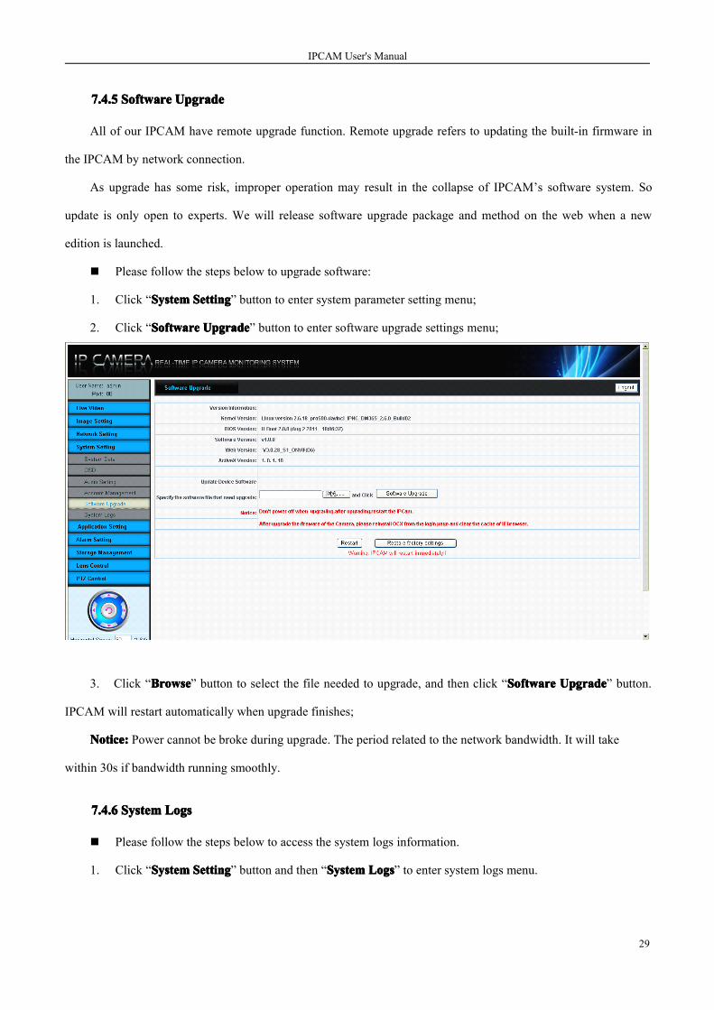
7.4.7.4.7.4.7.4.5555 SoftwareSoftwareSoftwareSoftware UpgradeUpgradeUpgradeUpgrade
All of our IPCAM have remote upgrade function. Remote upgrade refers to updating the built-in firmware in
the IPCAM by network connection.
As upgrade has some risk, improper operation may result in the collapse of IPCAM’s software system. So
update is only open to experts. We will release software upgrade package and method on the web when a new
edition is launched.
� Please follow the steps below to upgrade software:
1. Click “SystemSystemSystemSystem SettingSettingSettingSetting” button to enter system parameter setting menu;
2. Click “SoftwareSoftwareSoftwareSoftware UpgradeUpgradeUpgradeUpgrade” button to enter software upgrade settings menu;
3. Click “BrowseBrowseBrowseBrowse” button to select the file needed to upgrade, and then click “SoftwareSoftwareSoftwareSoftware UpgradeUpgradeUpgradeUpgrade” button.
IPCAM will restart automatically when upgrade finishes;
Notice:Notice:Notice:Notice: Power cannot be broke during upgrade. The period related to the network bandwidth. It will take
within 30s if bandwidth running smoothly.
7.4.7.4.7.4.7.4.6666 SystemSystemSystemSystem LogsLogsLogsLogs
� Please follow the steps below to access the system logs information.
1. Click “SystemSystemSystemSystem SettingSettingSettingSetting” button and then “SystemSystemSystemSystem LogsLogsLogsLogs” to enter system logs menu.

IPCAM User's Manual
30
2. There are three buttons, “Page 1”: view the first event; “Previous 20 Pages”: view the previous
20 events; “Next 20 Pages”: view the next 20 events.
FunctionFunctionFunctionFunction ButtonButtonButtonButton Instructions:Instructions:Instructions:Instructions:
●Page 1: View the first event.
●Previous 20 Pages: View the previous 20 events.
●Next 20 Pages: View the next 20 events.
7.57.57.57.5 ApplicationApplicationApplicationApplication
7.5.17.5.17.5.17.5.1 SDSDSDSD CardCardCardCard
1. Please click “SDSDSDSD CardCardCardCard” to enter the SD card settings menu.

IPCAM User's Manual
31
2. Insert SD card to the slot.
3. Select file format, format SD card and unmount SD card in the menu.
Notice:Notice:Notice:Notice:
SD card storage file format: AVI and JPEG.
7.5.27.5.27.5.27.5.2 ScheduledScheduledScheduledScheduled RecordRecordRecordRecord
� Please follow the steps below to set up scheduled record.
1. Click “Scheduled Record” button to enter scheduled settings menu;
2. Tick off and set up scheduled record time;

IPCAM User's Manual
32
3. Click “Submit” to complete the settings.
4. Remove the tick off, and SubmitSubmitSubmitSubmit to temporarily stop the scheduled task; CancelCancelCancelCancel ScheduleScheduleScheduleSchedule to clear the
scheduled task.
5. If you select “Video Circle Storage”, when the disk is full, it will delete the earliest created video file
folder to make room for continually recording.
7.67.67.67.6 AlarmAlarmAlarmAlarm SettingSettingSettingSetting
7.6.17.6.17.6.17.6.1 IOIOIOIO AlarmAlarmAlarmAlarm
� Please follow the steps below to set up alarm:
1. Click “IOIOIOIO AlarmAlarmAlarmAlarm” button to enter IO alarm setting menu;
2. Enable or disable the selected input switch;
3. Enable or disable the selected output switch;
4. Click “SubmitSubmitSubmitSubmit” button to complete the settings.
7.6.27.6.27.6.27.6.2 FaceFaceFaceFace DetectionDetectionDetectionDetection
IPCAM supports the front-end intelligent algorithm of face detection, which could provide the facedetection alarm message to the relevant back-end application. Users could make the second applicationdevelopment based on the algorithm.

IPCAM User's Manual
33
� Please follow the steps below to set up face detection:
1. Click “AlarmAlarmAlarmAlarm SettingSettingSettingSetting” button and select “FaceFaceFaceFace DetectionDetectionDetectionDetection” button to enter the face detection setting
menu:
2. Please select the face detection mode.
3. Click “Submit” button to complete the settings.
7.6.37.6.37.6.37.6.3 MotionMotionMotionMotion DetectionDetectionDetectionDetection
� Please follow the steps below to set up motion detection:
1. Click “AlarmAlarmAlarmAlarm SettingSettingSettingSetting” button and select “MotionMotionMotionMotion DetectionDetectionDetectionDetection” button to enter the motion detection setting
menu:

IPCAM User's Manual
34
2. Select the detection areas by mouse cursor.
3. Enable or disable motion detection;
4. Sensitivity: select the system options or customize (1~99).
5. Click “SubmitSubmitSubmitSubmit” button to transfer the new settings to IPCAM.
7.6.47.6.47.6.47.6.4 NetworkNetworkNetworkNetwork offoffoffoff AlarmAlarmAlarmAlarm
� Please follow the steps below to set up the network off alarm.
1. Click “NetworkNetworkNetworkNetwork offoffoffoff AlarmAlarmAlarmAlarm” to enter the network off alarm menu;
2. Select enable or disable network off alarm;
IPCAM User's Manual
35
3. Select the last time of alarming;
4. Click “SubmitSubmitSubmitSubmit” button to complete the settings.
7.77.77.77.7 StorageStorageStorageStorage ManagementManagementManagementManagement
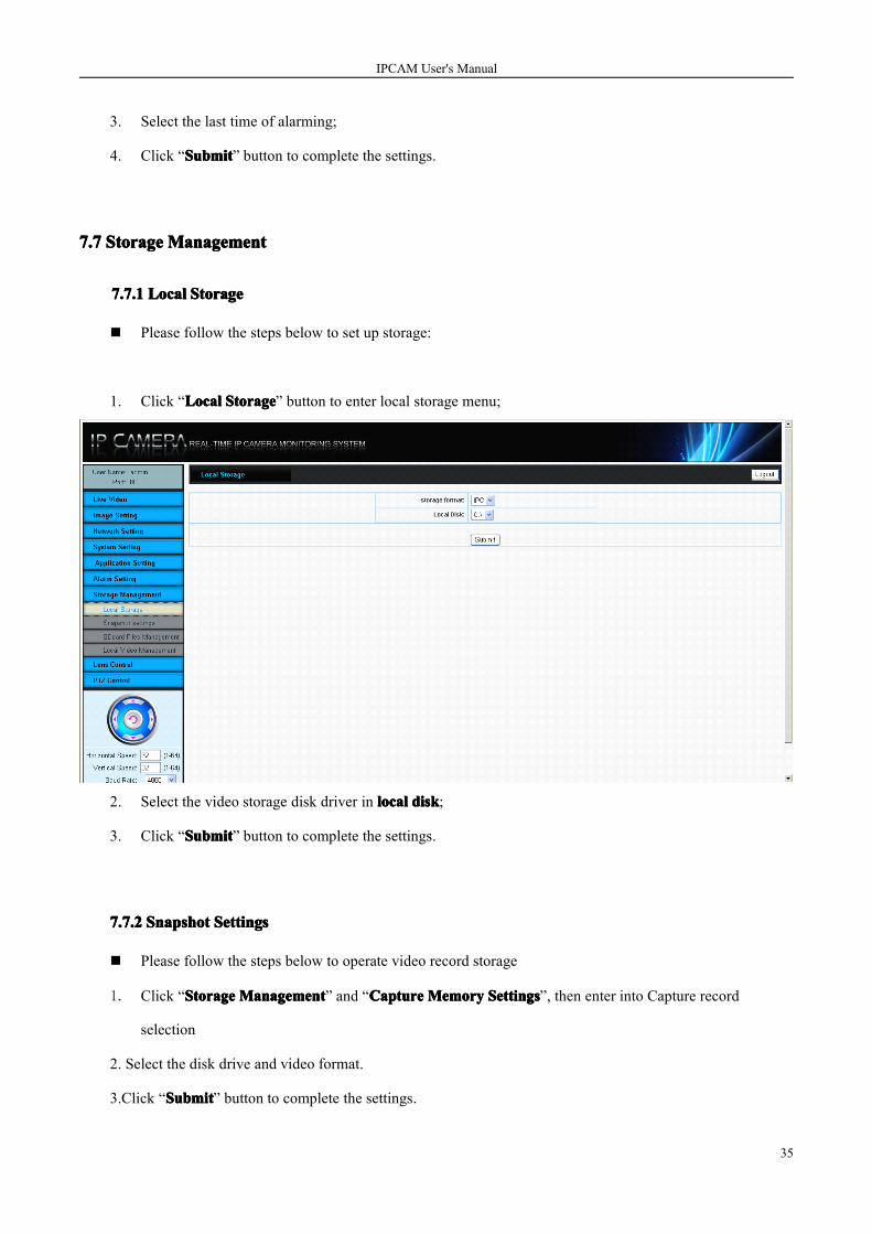
7.7.17.7.17.7.17.7.1 LocalLocalLocalLocal StorageStorageStorageStorage
� Please follow the steps below to set up storage:
1. Click “LocalLocalLocalLocal StorageStorageStorageStorage” button to enter local storage menu;
2. Select the video storage disk driver in locallocallocallocal diskdiskdiskdisk;
3. Click “SubmitSubmitSubmitSubmit” button to complete the settings.
7.7.27.7.27.7.27.7.2 SnapshotSnapshotSnapshotSnapshot SettingsSettingsSettingsSettings
� Please follow the steps below to operate video record storage
1. Click “StorageStorageStorageStorage ManagementManagementManagementManagement” and “CaptureCaptureCaptureCapture MemoryMemoryMemoryMemory SettingsSettingsSettingsSettings”, then enter into Capture record
selection
2. Select the disk drive and video format.
3.Click “SubmitSubmitSubmitSubmit” button to complete the settings.

IPCAM User's Manual
36
7.7.7.7.7.7.7.7.3333 SDSDSDSDccccardardardard FilesFilesFilesFiles ManagementManagementManagementManagement
� Please follow the steps below to operate SD card files management:
1. Click “StorageStorageStorageStorage ManagementManagementManagementManagement” and “SDSDSDSD CardCardCardCard FilesFilesFilesFiles ManagementManagementManagementManagement”, enter SD card files list window;
2. Each file can be downloaded by right click and save;
3. Each file can be deleted.

IPCAM User's Manual
37
7.7.7.7.7.7.7.7.4444 LocalLocalLocalLocal VideoVideoVideoVideoManagementManagementManagementManagement
� Please follow the steps below to control the local video management:
1. Click “LocalLocalLocalLocal VideoVideoVideoVideo ManagementManagementManagementManagement” button to enter local video management menu;
2. Select begin time and end time in datedatedatedate andandandand timetimetimetime options;
3. Click “PlayPlayPlayPlay” in the local video list to playback the videos; click “DeleteDeleteDeleteDelete” to delete it;

IPCAM User's Manual
38
4. Users could control the current playback video progress via player controls.
5. Thumb through the local record by click the button home page ,page up, page down and last page
7.87.87.87.8 LensLensLensLens andandandand PTZPTZPTZPTZ ControlControlControlControl
7.8.17.8.17.8.17.8.1 LensLensLensLens ControlControlControlControl
� Please follow the steps below to control the lens:
1. Click “LensLensLensLens ControlControlControlControl” button to enter the lens control window;

IPCAM User's Manual
39
2. Click the “+”, “-” button of Zoom, Focus, Iris to adjust lens.
7.8.27.8.27.8.27.8.2 PTZPTZPTZPTZControlControlControlControl
� Please follow the steps below to control PTZ:
1. Please click “PTZ Control” button to enter PTZ control window;
2. Please enter PTZ’s parameter in horizontal speed and vertical speed;
3. Click PTZ position menu to control camera’s PTZ;
Remarks:Remarks:Remarks:Remarks:
Please confirm that the PTZ protocol is Pelco-D before control PTZ and lens.
ⅧWANWANWANWAN AccessAccessAccessAccess
8.18.18.18.1 WANWANWANWANAccessAccessAccessAccess HDHDHDHD IPIPIPIP CAMCAMCAMCAMwithwithwithwith FixedFixedFixedFixed StaticStaticStaticStatic IPIPIPIP
If HD IP Camera adopts the static IP provided by ISP to enter public network, users can visit HD IP Camera
via IE when enter the static IP in the IE address. Users can visit via client software when adding into the list and
selecting the normal IP mode, enter the correct IP address, user name and password.

IPCAM User's Manual
40
8.28.28.28.2 WANWANWANWANAccessAccessAccessAccess HDHDHDHD IPIPIPIP CAMCAMCAMCAMwithoutwithoutwithoutwithout FixedFixedFixedFixed StaticStaticStaticStatic IPIPIPIP
This supports the network publishing system patent technology, which solves the using of WAN on IPCAM
completely. It achieves plug and play. Please follow the below steps to set up the WAN access on HD IP CAM:
StepStepStepStep One:One:One:One: ConfirmConfirmConfirmConfirm thethethethe routerrouterrouterrouter gateway.gateway.gateway.gateway. FollowFollowFollowFollow thethethethe belowbelowbelowbelow stepstepstepstep totototo obtainobtainobtainobtain thethethethe currentcurrentcurrentcurrent networknetworknetworknetwork parameter:parameter:parameter:parameter:
IPCAM User's Manual
41
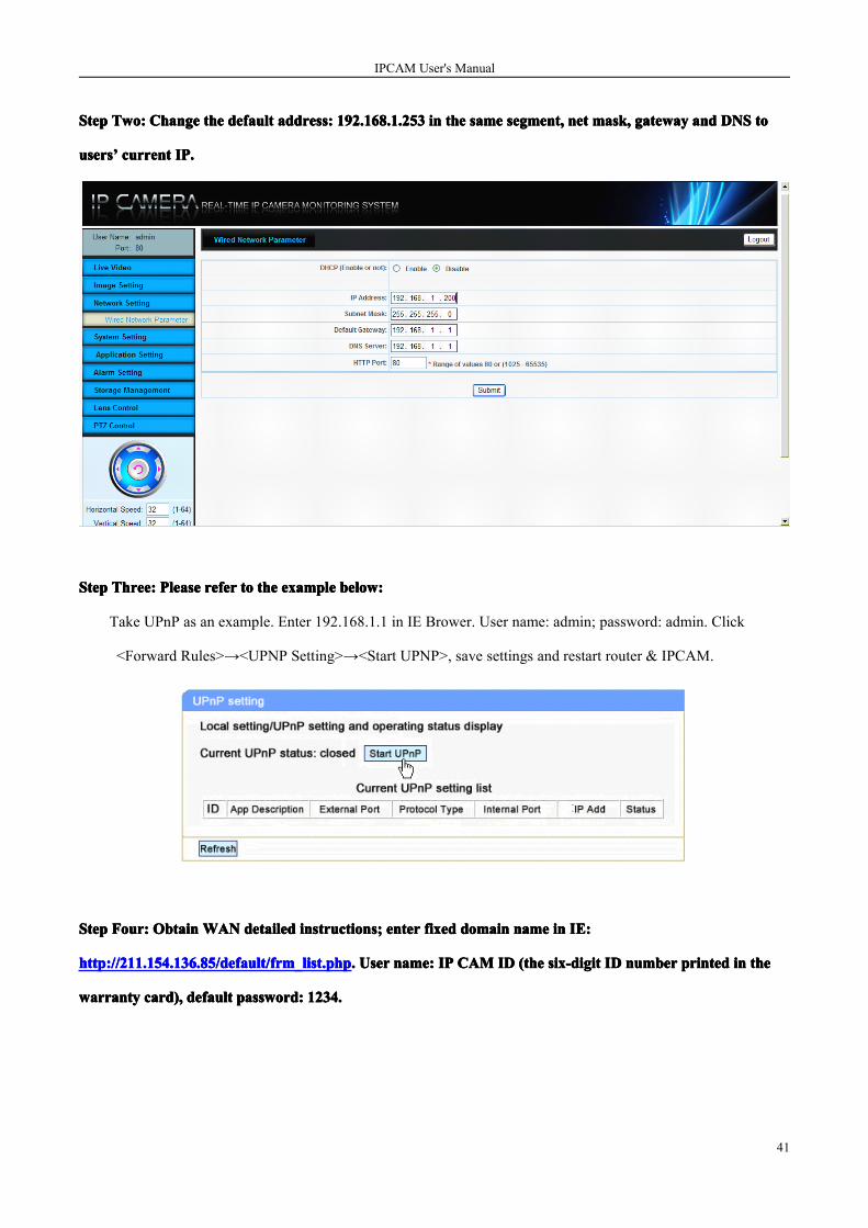
StepStepStepStep Two:Two:Two:Two: ChangeChangeChangeChange thethethethe defaultdefaultdefaultdefault address:address:address:address: 192.168.1.253192.168.1.253192.168.1.253192.168.1.253 inininin thethethethe samesamesamesame segment,segment,segment,segment, netnetnetnet mask,mask,mask,mask, gatewaygatewaygatewaygateway andandandand DNSDNSDNSDNS totototo
usersusersusersusers’’’’ currentcurrentcurrentcurrent IP.IP.IP.IP.
StepStepStepStep Three:Three:Three:Three: PleasePleasePleasePlease referreferreferrefer totototo thethethethe exampleexampleexampleexample below:below:below:below:
Take UPnP as an example. Enter 192.168.1.1 in IE Brower. User name: admin; password: admin. Click
<Forward Rules>→<UPNP Setting>→<Start UPNP>, save settings and restart router & IPCAM.
StepStepStepStep Four:Four:Four:Four: ObtainObtainObtainObtain WANWANWANWAN detaileddetaileddetaileddetailed instructions;instructions;instructions;instructions; enterenterenterenter fixedfixedfixedfixed domaindomaindomaindomain namenamenamename inininin IE:IE:IE:IE:
http://211.154.136.85/http://211.154.136.85/http://211.154.136.85/http://211.154.136.85/default/default/default/default/frm_list.phpfrm_list.phpfrm_list.phpfrm_list.php.... UserUserUserUser name:name:name:name: IPIPIPIP CAMCAMCAMCAM IDIDIDID (the(the(the(the six-digitsix-digitsix-digitsix-digit IDIDIDID numbernumbernumbernumber printedprintedprintedprinted inininin thethethethe
warrantywarrantywarrantywarranty card),card),card),card), defaultdefaultdefaultdefault password:password:password:password: 1234.1234.1234.1234.

IPCAM User's Manual
42
StepStepStepStep Five:Five:Five:Five: LogLogLogLog inininin thethethethe administrativeadministrativeadministrativeadministrative platform,platform,platform,platform, thethethethe pop-uppop-uppop-uppop-up websitewebsitewebsitewebsite isisisis thethethethe InternetInternetInternetInternet accessaccessaccessaccess address.address.address.address.
Ⅸ FAQFAQFAQFAQ
� WhyWhyWhyWhy usersusersusersusers cannotcannotcannotcannot visitvisitvisitvisit HDHDHDHD IPIPIPIP CameraCameraCameraCamera viaviaviavia browsers?browsers?browsers?browsers?
A: Possible cause: Network doesn’t work.
Solution: Check whether the network access works well. Get rid of the cable and virus problem until PC can be
pinged.
B: Possible cause: IP address is dominated by other equipment.
Solution: Disconnect HD IP CAM and network, connect HD IP CAM with PC separately, and reset IP address.
C: Possible cause: IP address is in different subnet.
Solution: Check the setup of server IP address, net mask and gateway.
D: Possible cause: N/A.
Solution: Click “reset” button at the back of HD IP CAM to default status.
���� WhyWhyWhyWhy errorerrorerrorerror occursoccursoccursoccurs whenwhenwhenwhen visitvisitvisitvisit HDHDHDHD IPIPIPIP CAMCAMCAMCAM viaviaviavia browserbrowserbrowserbrowser afterafterafterafter update?update?update?update?
Delete browser’s cache memory.

IPCAM User's Manual
43
���� ImagesImagesImagesImages areareareare notnotnotnot clear.clear.clear.clear.
When iris is fully open and focus is not clear, please check the lens interface. If C mounts, C adapter should be
added.
� IsIsIsIs itititit anyanyanyany problemsproblemsproblemsproblems totototo drawdrawdrawdraw outoutoutout SDSDSDSD cardcardcardcard whilewhilewhilewhile recording?recording?recording?recording?
Please do not draw out SD card while HD IP CAM or SD card is working, and indicator light turns red as the
picture shows ,.
� MotionMotionMotionMotion detectiondetectiondetectiondetection isisisis alreadyalreadyalreadyalready setsetsetset up,up,up,up, butbutbutbut doesndoesndoesndoesn’’’’tttt work.work.work.work.
Please confirm whether the motion region or sensitivity is set up; Sensitivity value is too low.
AppendixAppendixAppendixAppendix 1:1:1:1: ReticleReticleReticleReticle MakingMakingMakingMaking
(1) HD IP Camera Ethernet port twisted with HUB (Direct Line):
(2) HD IP Camera Ethernet port twisted with HUB (Cross Line):

IPCAM User's Manual
44
AppendixAppendixAppendixAppendix 2:2:2:2: TechnicalTechnicalTechnicalTechnical ParameterParameterParameterParameter
TechniqueTechniqueTechniqueTechnique ParameterParameterParameterParameter
VideoVideoVideoVideo CodecCodecCodecCodec H.264/MPEG4/M-JPEG
ResolutionResolutionResolutionResolution 1920*1080/1280*720/640*352/352*192
VideoVideoVideoVideo FrameFrameFrameFrame RateRateRateRate 1-30fps
VideoVideoVideoVideo CompressCompressCompressCompress RateRateRateRate 64K~16Mbps (CBR), (CVBR)
Min.Min.Min.Min. Lux.Lux.Lux.Lux. Color:1Lux @ F1.2,B/W:[email protected]
LensLensLensLens C/CS mount
AutoAutoAutoAuto ApertureApertureApertureAperture Support
AnalogAnalogAnalogAnalog VideoVideoVideoVideo OutputOutputOutputOutput InterfaceInterfaceInterfaceInterface 1 channel
MotionMotionMotionMotion DetectionDetectionDetectionDetection Support 4x3 region grids; sensitivity: 6
Multi-streamMulti-streamMulti-streamMulti-stream Support 1~3 streams
AudioAudioAudioAudio CompressionCompressionCompressionCompression G.726
AudioAudioAudioAudio RateRateRateRate 64Kbps/10.2Kbps
AudioAudioAudioAudio I/OI/OI/OI/O 1 input; 1 output
CableCableCableCable NetworkNetworkNetworkNetwork 1 RJ45 10M/100M
USBUSBUSBUSB interfaceinterfaceinterfaceinterface 1 channel
AlarmAlarmAlarmAlarm I/OI/OI/OI/O 2 input; 1 output
LocalLocalLocalLocal StorageStorageStorageStorage Support on-board SD card
RS485RS485RS485RS485 support multiple PTZ Control Protocol
PowerPowerPowerPower SupplySupplySupplySupply DC12V±10%
PowerPowerPowerPower <3W
OperatingOperatingOperatingOperating ConditionConditionConditionCondition Temperature -20 ~ +60°C, Humidity 20 ~ 80%
StorageStorageStorageStorage ConditionConditionConditionCondition Temperature -30 ~ +80°C, Humidity 20 ~ 95 %
DimensionDimensionDimensionDimension 125(L)x89(W)x55(H)
NetworkingNetworkingNetworkingNetworking ProtocolProtocolProtocolProtocol Support standard protocols
NetworkNetworkNetworkNetwork BrowserBrowserBrowserBrowser AccessAccessAccessAccess Built-in WEB Serve, Support IE Brower
SecuritySecuritySecuritySecurityPasswords protection, support different users classes tomanage
Max.Max.Max.Max. VisitorsVisitorsVisitorsVisitors Support 10 visitor at the same time