ION - P8ntbox Paintball news, occasions paintball, … Ion is a high performance tournament grade...
27
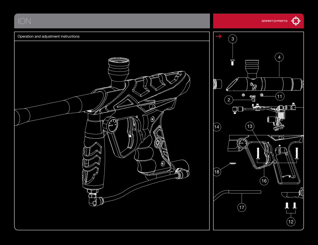
ION 3 4 2 11 14 18 16 17 12 13 Operation and adjustment instructions
Transcript of ION - P8ntbox Paintball news, occasions paintball, … Ion is a high performance tournament grade...
ION
1
3
4
6
10
5
7
8
15
211
14
18
16
17
12
13
9
Operation and adjustment instructions
QUICK START
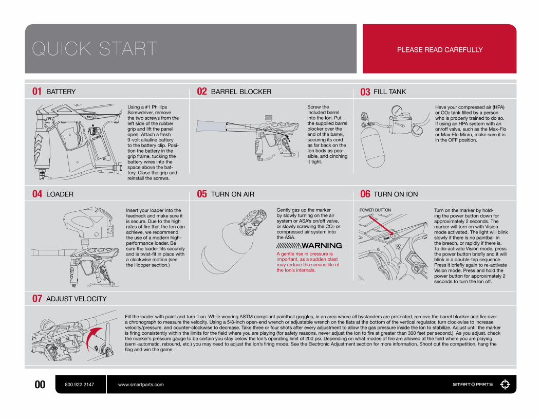
01 02 03Using a #1 Phillips Screwdriver, remove the two screws from the left side of the rubber grip and lift the panel open. Attach a fresh 9-volt alkaline battery to the battery clip. Posi-tion the battery in the grip frame, tucking the battery wires into the space above the bat-tery. Close the grip and reinstall the screws.
Screw the included barrel into the Ion. Put the supplied barrel blocker over the end of the barrel, securing its cord as far back on the Ion body as pos-sible, and cinching it tight.
Fill the loader with paint and turn it on. While wearing ASTM compliant paintball goggles, in an area where all bystanders are protected, remove the barrel blocker and fire over a chronograph to measure the velocity. Using a 5/8-inch open-end wrench or adjustable wrench on the flats at the bottom of the vertical regulator, turn clockwise to increase velocity/pressure, and counter-clockwise to decrease. Take three or four shots after every adjustment to allow the gas pressure inside the Ion to stabilize. Adjust until the marker is firing consistently within the limits for the field where you are playing (for safety reasons, never adjust the Ion to fire at greater than 300 feet per second.) As you adjust, check the marker’s pressure gauge to be certain you stay below the Ion’s operating limit of 200 psi. Depending on what modes of fire are allowed at the field where you are playing (semi-automatic, rebound, etc.) you may need to adjust the Ion’s firing mode. See the Electronic Adjustment section for more information. Shoot out the competition, hang the flag and win the game.
Insert your loader into the feedneck and make sure it is secure. Due to the high rates of fire that the Ion can achieve, we recommend the use of a modern high-performance loader. Be sure the loader fits securely and is twist-fit in place with a clockwise motion (see the Hopper section.)
Gently gas up the marker by slowly turning on the air system or ASA’s on/off valve, or slowly screwing the CO2 or compressed air system into the ASA.
A gentle rise in pressure is important, as a sudden blast may reduce the service life of the Ion’s internals.
Turn on the marker by hold-ing the power button down for approximately 2 seconds. The marker will turn on with Vision mode activated. The light will blink slowly if there is no paintball in the breech, or rapidly if there is. To de-activate Vision mode, press the power button briefly and it will blink in a double-tap sequence. Press it briefly again to re-activate Vision mode. Press and hold the power button for approximately 2 seconds to turn the Ion off.
04 05 06
BATTERY BARREL BLOCKER FILL TANK
LOADER TURN ON AIR TURN ON ION
ADJUST VELOCITY07
00 800.922.2147 www.smartparts.com
PLEASE READ CAREFULLY
Have your compressed air (HPA) or CO2 tank filled by a person who is properly trained to do so. If using an HPA system with an on/off valve, such as the Max-Flo or Max-Flo Micro, make sure it is in the OFF position.
POWER BUTTON

Quick Start
Getting Familiar
Barrel Blocker/Hopper
Gases
Gas System Mounting
Paint/Velocity
Vision/Degassing
Electronic Adjustment
Dwell
ROF Delay/Fire Modes
Trigger Adjustment
Ion Parts
Disassembly
Reassembly
Solenoid
Regulator
Ball Detents
Troubleshooting
Warranty/Tech Support
CPS Table
00
02
03
04-05
06
07
08
09
10
11
12
13
14-15
16
17
18
19
20-23
23
24
TABLE OF CONTENTS
01800.922.2147 www.smartparts.com
– THE ION IS NOT A TOY
– MISUSE OF THE ION MAY RESULT IN SERIOUS INJURY OR DEATH.
– EYE PROTECTION SPECIFICALLY DESIGNED FOR PAINT- BALL USE MUST BE IN COMPLIANCE WITH ASTM SPECI- FICATION F1776 AND MUST BE USED BY THE USER AND ANYONE WITHIN RANGE OF THE ION.
– SMART PARTS RECOMMENDS THAT THE ION ONLY BE SOLD TO PERSONS 18 AND OLDER.
– THOROUGHLY READ THE ION OPERATION AND INSTRUCTION MANUAL BEFORE OPERATING.
– TREAT EVERY PAINTBALL MARKER AS IF IT WERE LOADED.
– NEVER LOOK DOWN THE BARREL OF A PAINTBALL MARKER.
– KEEP YOUR FINGER OFF THE TRIGGER UNTIL READY TO SHOOT.
– NEVER POINT THE ION AT ANYTHING YOU DON’T WISH TO SHOOT.
– KEEP THE ION ON SAFE (POWER OFF) UNTIL READY TO SHOOT. (SEE QUICK START)
– KEEP THE BARREL BLOCKING DEVICE ON THE ION’S MUZZLE WHEN NOT SHOOTING. (SEE BARREL BLOCKER SECTION).
– ALWAYS REMOVE PAINTBALLS AND DEGAS THE ION BEFORE DISASSEMBLY. (SEE DEGAS- SING SECTION.)
– STORE AND TRANSPORT THE ION UN- LOADED AND DEGASSED IN A SECURE PLACE.
– FOLLOW ALL MANUFACTURER’S WARNINGS AND INSTRUCTIONS FOR PROPELLANT SOURCE HANDLING, STORAGE, AND FILLING.
– DO NOT SHOOT FRAGILE OBJECTS SUCH AS WINDOWS.
– ALWAYS MEASURE THE VELOCITY OF PAINTBALLS FIRED BY THE ION BEFORE USE, AND NEVER ADJUST TO FIRE ABOVE 300FPS (91.44 M/S.)While every effort has been made to ensure that the information contained in this guide is accurate and complete, no liability can be accepted for er-
rors or omissions. Smart Parts, Inc. reserves the right to change the specifications of the Ion at any time without prior notice. The latest version of this manual may be downloaded free of charge at www.SmartParts.com.
MAINTENANCE
The Ion has been designed with simplicity in mind so that you can concentrate on your game instead of your marker. It has a minimal number of moving parts and seals so that you can maintain the marker with little effort. This DOES NOT mean that you should neglect your marker. If you take care of it off the field, your Ion will take care of you on the field. For best performance, clean and grease your Ion frequently. Many players clean their marker after every use. While this may seem a bit extreme, being vigilant in the upkeep of your marker will extend its useful life considerably. Playing in the rain will not damage your Ion, but you should NEVER immerse it in water. If your marker should become waterlogged, remove the barrel, body cover and rubber grips and allow them to dry out, then follow the disassembly instructions for full cleaning. Clean out mud and paint with a damp cloth and alcohol. Grease the Ion ONLY with SL33K pneu-matic grease. For best performance, use high quality paintballs.
STATISTICS
LENGTH/HEIGHT/WEIGHT:
OPERATING PRESSURE:
PAINTBALLS:
POWER SOURCE:
PROPELLANT:
RATE OF FIRE:
OPERATION:
MODES OF FIRE:
ANTI CHOP SYSTEM:
BARREL THREAD:
GAS EFFICIENCY:
LUBRICANT:
18 Inches (with stock 12” barrel) / 8.5 Inches (with ASA) / 2lbs, 2oz (marker only)
Approx. 180 psi, 200 psi max
.68 caliber –Compliant to ASTM F1979 Specification
9-volt alkaline battery
CO2 or Nitrogen/Compressed air
17 bps maximum – 20 bps max with optional Blackheart board
Low pressure electropneumatic
Full Auto, 3-shot burst, Semi automatic and Rebound
Break Beam Vision
Smart Parts (Impulse/Ion)
1200 shots (68ci, 4500psi tank), 800 shots (20oz. ANTI-SIPHON tank) – Efficiency will vary with paint, barrel and setting combinations.
For proper and consistent operation, the Ion should only be lubricated with SL33K lubricating grease.
GETT ING FAMIL IAR
02 800.922.2147 www.smartparts.com
PLEASE READ CAREFULLY
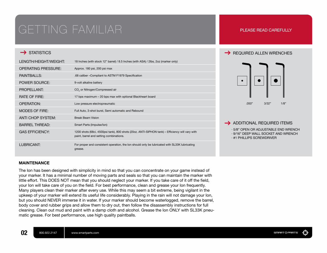
REQUIRED ALLEN WRENCHES
.050” 3/32” 1/8”
· 5/8” OPEN OR ADJUSTABLE END WRENCH· 9/16” DEEP WALL SOCKET AND WRENCH· #1 PHILLIPS SCREWDRIVER
ADDITIONAL REQUIRED ITEMS
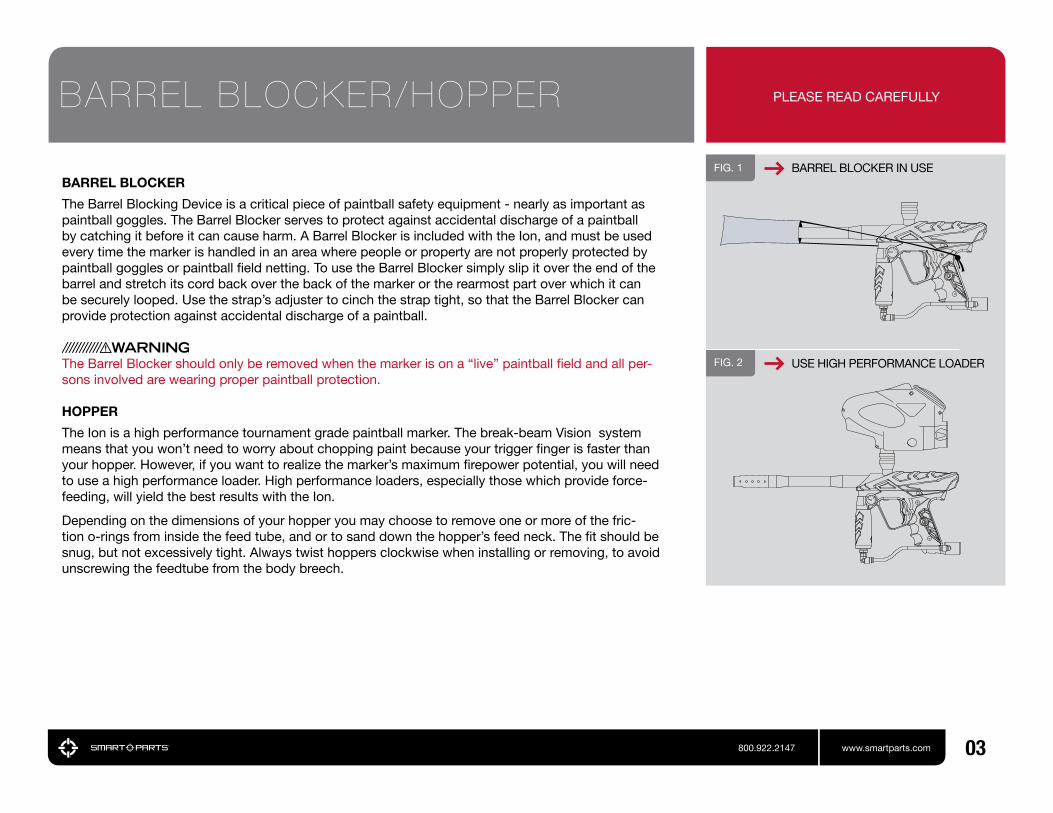
FIG. 1
FIG. 2
BARREL BLOCKER IN USE
USE HIGH PERFORMANCE LOADER
BARREL BLOCKER
The Barrel Blocking Device is a critical piece of paintball safety equipment - nearly as important as paintball goggles. The Barrel Blocker serves to protect against accidental discharge of a paintball by catching it before it can cause harm. A Barrel Blocker is included with the Ion, and must be used every time the marker is handled in an area where people or property are not properly protected by paintball goggles or paintball field netting. To use the Barrel Blocker simply slip it over the end of the barrel and stretch its cord back over the back of the marker or the rearmost part over which it can be securely looped. Use the strap’s adjuster to cinch the strap tight, so that the Barrel Blocker can provide protection against accidental discharge of a paintball.
The Barrel Blocker should only be removed when the marker is on a “live” paintball field and all per-sons involved are wearing proper paintball protection.
HOPPER
The Ion is a high performance tournament grade paintball marker. The break-beam Vision system means that you won’t need to worry about chopping paint because your trigger finger is faster than your hopper. However, if you want to realize the marker’s maximum firepower potential, you will need to use a high performance loader. High performance loaders, especially those which provide force-feeding, will yield the best results with the Ion.
Depending on the dimensions of your hopper you may choose to remove one or more of the fric-tion o-rings from inside the feed tube, and or to sand down the hopper’s feed neck. The fit should be snug, but not excessively tight. Always twist hoppers clockwise when installing or removing, to avoid unscrewing the feedtube from the body breech.
BARREL BLOCKER/HOPPER
03800.922.2147 www.smartparts.com
PLEASE READ CAREFULLY

Never put oil in a compressed air regulator or tank—only apply manufacturer specified lubricants.
The Ion is a low-pressure paintgun. It operates optimally at 180 psi, which means it can function well with either compressed air or CO2 as a power source. Proper set up of your gas system will help you obtain the best possible performance.
High Pressure Air systems (HPA) are the most common power source used with the Ion, as they are unaffected by temperature fluctuations and do not have the potential for liquid problems. HPA systems consist of a tank and a regulator, and are typically rated to store air or nitrogen (while pure nitrogen is almost never used in paintball, many players call compressed air “nitro” as air is made of more than 70% nitrogen) at pressures of 3,000 or 4,500 psi.
There are two main types of HPA systems, those on which the output pressure is adjustable, and those for which their regulator is pre-set to a fixed output pressure. HPA systems designed to screw into an ASA are usually pre-set to deliver either 400 psi (low pressure output) or 800 psi (high pressure output.)
Never use oil or any petroleum based cleaner or lubricant in a compressed air regulator or tank. Ex-posure to pressurized air increases oil’s flammability and can cause a serious safety hazard. Only use manufacturer recommended lubricants with compressed air systems, and follow the manufacturer’s maintenance and operation instructions explicitly.
If you are using your Ion with an adjustable output compressed air system, it should be adjusted to de-liver about 650 psi to the marker’s vertical regulator. The Ion’s regulator can accommodate a wide range of input pressures, so exact adjustment of the air system is not critical, and either low output, or high output pre-set HPA systems may be used as well.
While CO2 can also be used, it is less popular, since its pressure fluctuates with temperature and use. The important thing to remember when using CO2 is that liquid CO2 must not be delivered to the marker. If liquid CO2 were to make it past the vertical regulator, it could expand into gas form inside the paintgun, raising the pressure levels high enough to cause damage to internal seals, hoses or the solenoid valve. Because liquid CO2 is heavier than CO2 gas, it is easily blocked through the use of gravity.
FIG. 3 HPA TANK BEING FILLED
GASES
04 800.922.2147 www.smartparts.com
FIG. 4
FIG. 5
COMPRESSED AIR
CO2 WITH ANTI-SIPHON [CUTAWAY VIEW]

GASES
05800.922.2147 www.smartparts.com
PLEASE READ CAREFULLY
IMPORTANTCO2 can also be used with remote hose with-out Anti-Siphon. [Not Shown]
Two easy ways to properly use CO2 with the Ion are an anti-siphon tank or a remote line.
Anti-siphon tanks have a J shaped tube professionally installed inside. When the tank is screwed into a bottom line ASA, such as the one that is standard on the Ion, the tube delivers gas only. The anti-siphon tube works like a diver’s snorkel, repositioning the gas intake from the valve to the top side of the tank. When an anti-siphon tube is installed in a tank, the airsmith will usually mark the valve, to indicate the position of the tube. When the tank is screwed into a marker, this mark must be oriented to the top.
A remote hose allows a standard (non-siphoned) CO2 tank to be carried in a player’s pack. Not only does this reduce the total weight of the marker, but it also allows the tank to be placed vertically, so that its valve is at the top while gravity holds the liquid CO2 at the bottom. It is important to note that lying down on the field or crawling while using a remote can cause liquid CO2 to be fed to the paintgun as the tank is turned on its side.
Whether using compressed air or CO2 it is important that the marker is not exposed to sudden “pops” of pressure. If using a standard ASA with a screw in HPA system or CO2 tank, screw the tank in slowly, so that the valve opens slowly and the pressure rises gently. If using an ASA with a built in on/off valve, screw in the tank fully, then open the valve slowly. If using an HPA system or CO2 tank with its own on/off valve, open that valve slowly. Be gentle to the internals of your marker and they will reward you with a long service life.

FIG. 6 BOTTOM OF GRIP FRAME
The Ion uses paintball industry standard gas system mounting. At the bottom of the grip frame, it has a pair of 10-32 screw holes.
The Ion is preconfigured with a standard duckbill style ASA mounted on bottom of the grip frame. To remove this ASA, degas and unload the marker. Use a 1/8” allen wrench to remove the two ASA mount screws. The ASA can be replaced with a mounting rail or drop forward to place the gas source in a position that is most comfortable for you.
GAS SYSTEM MOUNTING
06 800.922.2147 www.smartparts.com
PLEASE READ CAREFULLY
PAINT
Even the best quality paintballs will vary in size from one batch to the next and as weather conditions change. While your marker will work well even with a poor paint to barrel fit, optimal performance will be achieved with a proper fit. Paintgun barrels are available in a variety of bore sizes to allow the user to select the best possible fit, and barrel kits like The Freak allow for easy adjustment to paint of different diameters.
The ideal fit between the paintball and the barrel is when the ball is inserted in the bore (the end that screws into the marker) and does not slip or roll through to the muzzle (the business end) on its own. The ball should sit in place, even when the barrel is pointed straight down. If the paintball can roll out on its own, the fit is too loose. The ball should be able to be expelled from the barrel by blowing it out like a blowgun, using a minimal amount of breath. If the ball is difficult to blow through, the fit is too tight, which can lead to ball breakage.
VELOCITY
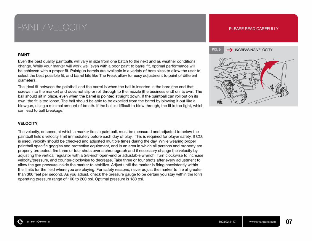
The velocity, or speed at which a marker fires a paintball, must be measured and adjusted to below the paintball field’s velocity limit immediately before each day of play. This is required for player safety. If CO2 is used, velocity should be checked and adjusted multiple times during the day. While wearing proper paintball specific goggles and protective equipment, and in an area in which all persons and property are properly protected, fire three or four shots over a chronograph and if necessary change the velocity by adjusting the vertical regulator with a 5/8-inch open-end or adjustable wrench. Turn clockwise to increase velocity/pressure, and counter-clockwise to decrease. Take three or four shots after every adjustment to allow the gas pressure inside the marker to stabilize. Adjust until the marker is firing consistently within the limits for the field where you are playing. For safety reasons, never adjust the marker to fire at greater than 300 feet per second. As you adjust, check the pressure gauge to be certain you stay within the Ion’s operating pressure range of 160 to 200 psi. Optimal pressure is 180 psi.
07800.922.2147 www.smartparts.com
PLEASE READ CAREFULLYPAINT / VELOCITY
INCREASING VELOCITYFIG. 9

PROGRAMMING BUTTON/LEDFIG. 10
PROGRAMING BUTTON
LEDs
VISION INSTRUCTIONS
When the Ion is turned on it will be in Vision mode. The internal infra-red eye will be used to detect whether or not a paintball is in the breech. This feature practically eliminates the possibility of a chopped paintball. Vision mode is indicated by a rapid blinking of the light in the power button when there is a paintball in the breech, or a slow blinking when it is empty. Vision mode can be de-activated by pressing the power button quickly while the marker is on. Vision mode off is indicated by a double-tap blink-ing pattern on the power button light. Vision mode may be turned back on by once again pressing the power button briefly.
DEGASSING
At the end of each day’s use and before performing maintenance work on your marker, it will need to be degassed, and all paintballs must be removed. In an area where it is safe to shoot (such as the chrono-graph area at a paintball field) and while wearing paintball goggles, remove the hopper from the feed-neck. By turning the marker upside down, you can empty any extra paintballs from the feedneck into your hand. Turn the marker on, then deactivate Vision mode by pressing the power button momentarily. Dry-fire 2 or 3 shots in a safe direction to ensure that no paintballs remain in the marker. Turn off the compressed air system or on/off ASA, or unscrew the compressed air system or CO2 tank far enough to close its pin valve.
Continue to dry fire the marker in a safe direction until all of the gas pressure inside has been released. At this point the only sound you should hear when you pull the trigger is the click of the solenoid valve. Turn off the Ion by pressing and holding the power button for two or more seconds.
If using a CO2 tank or screw in HPA system, unscrew it the rest of the way.
If the marker is to be stored for an extended period of time, remove the 9-volt battery from the grip frame.
V IS ION/DEGASSING PLEASE READ CAREFULLY
Even with no CO2 tank or compressed air system attached, the marker may still have enough gas pressure stored in the regulator and fire chamber to fire 2 or more shots. You must degas your marker before storage or maintenance.
08 800.922.2147 www.smartparts.com

PROGRAMMING EXAMPLETo set a dwell value of 18ms, first press the programming button as many times as needed to light the red programming LED solidly. Then press and hold the power but-ton until the red LED blinks alone, indicating that the bottom of the adjustment range (8ms) has been reached. Press the pro-gramming button again to cycle through the programming modes until the yellow LED is lit solidly indicating Dwell Up function. Then, press the upper power button 20 times (20 button presses x 0.5ms = 10ms increase or 18ms total.) Pull the trigger to exit the pro-gramming mode and save the setting.
ELECTRONIC ADJUSTMENT
Dwell, Rate of Fire Delay and Mode adjustments are made using the marker’s programming button and power button. Removing the two grip screws on the left side of the Ion’s grip frame and folding the grip back provides access to the programming button. The button is small, gray and rectangular in shape. It is mounted on the circuit board facing the left edge for easy access. A notch in the board helps to identify the button and make it easier to press.
Yellow and red light emitting diodes (LEDs) are located on the circuit board just above the programming button. The patterns which flash on these buttons indicate the function the power button will perform when pressed.
To enter the programming modes, make sure the Ion is completely degassed and unloaded, with a barrel blocker properly in place. Turn the marker on and note that the programming LEDs are not lit or flashing. This indicates that the Ion is in operational mode rather than a programming mode. To select one of the programming modes, press the programming button and note the sequence of blinking LEDs to determine which mode you have selected. The yellow LED indicates that you have selected to increase a setting, and the red LED indicates that you have chosen to decrease a setting. The LED will be lit solidly for adjustment of the dwell, single blink for adjustment of the ROFDelay and double blink for adjustment of the firing mode.
To change a particular setting, choose the appropriate mode, then press the power button. Both LEDs will blink to acknowledge that the adjustment has been made. When only the red LED blinks after pressing the power button, this indicates that you have reached the lower limit of adjustment. Similarly only the yellow LED will blink to indicate that the upper adjustment limit has been reached. Pull the trig-ger to exit the programming mode and save your new settings.
SETTING LIGHT INDICATION MODE FUNCTION
ELECTRONIC ADJUSTMENT
09800.922.2147 www.smartparts.com
IMPORTANT
ONE
TWO
THREE
FOUR
FIVE
SIX
Dwell Up [solid yellow]
Dwell Down [solid red]
ROF Delay Up [shoot slower/blink yellow]
ROF Delay Down [shoot faster/blink red]
Firing Modes Up [double blink yellow]
Firing Modes Down [double blink red]
REMOVE RUBBER GRIPFIG. 12
FIG. 11 TURNING ON THE ION
POWERBUTTON
The dwell setting determines how long the Ion holds open its solenoid valve, which ultimately affects how much gas is released to fire each shot. It is important to balance the dwell and the operating pres-sure (the setting of the vertical regulator). Too high of a dwell with a low operating pressure will cause poor gas efficiency and velocity drop-off. Too low of a dwell will leave the marker unable to properly cycle through a full firing sequence. Dwell adjustment should be performed after changing internal com-ponents such as the bolt or installation of a quick exhaust valve (QEV.) Dwell setting changes should not be used to adjust velocity.
The dwell value can be adjusted between 8 milliseconds (1ms = 0.001 seconds) and 52ms in 0.5ms increments. To adjust the dwell, make sure the marker is already turned on, select the proper adjustment mode for Dwell Up or Dwell Down and press the power button once for every .5ms change desired.
To optimize your dwell setting, wear proper paintball protective goggles and gas up your Ion with a barrel blocker in place, with no paint or hopper. Turn on the Ion and press the power button once to de-activate Vision mode. Decrease the dwell time (solid red adjustment mode) until the Ion can no longer complete a full firing cycle (bolt does not close all the way) each time you pull the trigger. Increase the dwell value (solid yellow adjustment mode) one button press at a time, test firing after each change until you hear the Ion fire a full volume shot. Increase the dwell by an additional 15 to 20 button presses to reach the set-ting for best gas efficiency.
If your new setting causes an increase in first shot drop off, where the marker is at rest for an extended period of time and has reduced velocity or will not fire on the first shot but fires fine after that, first disassemble, clean and lubricate the Ion bolt assembly and repeat the dwell setting procedure. If this does not eliminate the problem, further increase the dwell setting until there is no longer a sluggish first shot.
DWELL
10 800.922.2147 www.smartparts.com

ROF DELAY
The Rate of Fire Delay (ROFDelay) adjustment determines how long the Ion must wait after it shoots, before the next shot can be fired. This delay allows time for the bolt to return to its rear position, gas pressure in the fire chamber to be recharged, and for a new paintball to fall into the breech. Increasing the Rate Of Fire Delay setting will decrease the maximum rate of fire the marker is capable of achiev-ing. Many players will set the ROFDelay to its minimum, relying on the Vision system to determine when the marker is ready to fire. Setting a higher ROFDelay can be useful if there is a Vision problem, or when playing at tournaments or fields which limit players to shooting 15 balls per second or slower.
The Rate of Fire Delay setting is adjustable from 25ms to 70ms in 0.5ms intervals. To change the rate of fire setting, while the Ion is turned on, press the programming button to select the ROFDelay Up mode (single blink yellow – SLOWER ) or ROFDelay Down mode (single blink red - FASTER.)
As with the dwell settings blink of only the red or yellow light only when the power button is pressed indi-cates you have reached the limit of adjustment.
FIRING MODES
The Ion features four distinct firing modes which can all be selected by increasing (double blink yellow) or decreasing (double blink red) the firing mode setting. Mode 0 is Semi-Automatic and fires one shot per trigger pull. Mode 1 is Rebound and fires more than one shot per trigger pull when the trigger is pulled at a constant, rapid pace. Mode 2 is 3-Shot Burst which fires up to three consecutive shots when the trigger is pulled and held. If the trigger is released before the 3 shots have been fired, the marker will stop firing. Mode 3 is Full-Automatic, which will fire repeatedly while the trigger is held back. The maximum rates of fire that can be achieved in semi-automatic and Rebound modes will depend on the marker’s Dwell and Rate of Fire Delay settings. Both 3-shot burst and full-automatic fire at a rate of 10 shots per second. Ions manufactured for the United Kingdom can be identified by a green (instead of red) power button LED and do not include 3-shot burst or full auto modes.
To select Semi-Auto mode, degas and unload the marker as with other mode adjustments. Turn the power on, and press the programming button as many times as needed to cycle the programming LEDs to a red double-blink pattern (Firing Modes Down.) Press and hold the power button until the LEDs blink red, indicating that the lowest mode (0- Semi-Automatic) is reached. Tap the trigger to exit programming mode. To select other modes, first set the Ion to semi-automatic mode, but do not press the trigger. Then press the programming button 5 times to choose Firing Modes Up (double blink yellow) and press the power button the number of times needed to select the desired mode – once for Rebound, twice for 3-Shot Burst, and three times for Full Auto.
RATE OF FIREIt is important to remember that the ROF setting is not the same as a rate of fire cap, or the maximum rate of fire the Ion can achieve. The maximum rate of fire or Cycles Per Second (CPS) is calculated from a combination of the Dwell setting and the ROF setting.Cycle Time (milliseconds) = Dwell + ROF
The length of time needed for one com-plete cycle equals the Dwell time plus the ROF time (time in milliseconds, not number of chirps.)Cycle Time (Seconds) = Cycle Time (milliseconds) / 1,000
To calculate the maximum CPS, the cycle time will need to be converted from milliseconds to seconds. This is done by dividing it by 1,000.CPS = 1 Second / Cycle Time (seconds)
The maximum cycle rate of an Ion, for any given Dwell and ROF settings can be easily calculated. Divide one second by the cycle time to arrive at the number of shots per second.For fields or tournaments which require paintguns be limited to a maximum rate of fire, you will need to make sure the Dwell of your marker is properly adjusted and then calculate the proper ROF value to create the desired CPS limit. See the CPS table for examples.
ROF DELAY/F IR ING MODES
11800.922.2147 www.smartparts.com
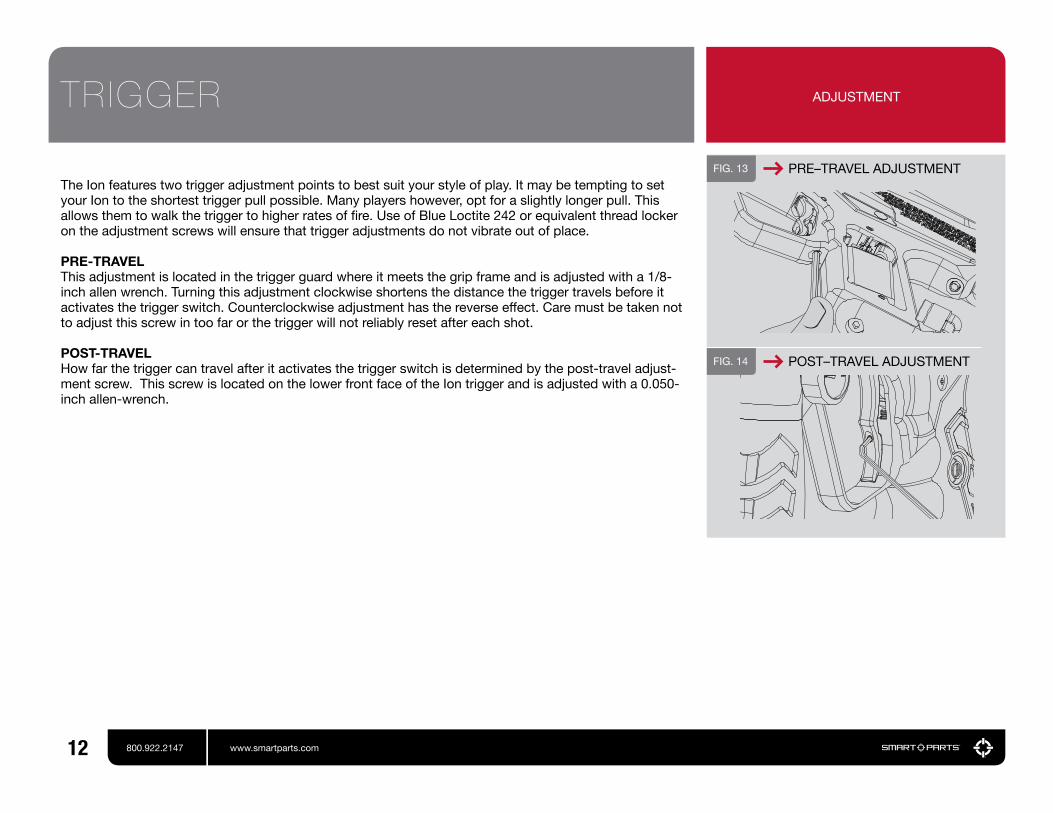
The Ion features two trigger adjustment points to best suit your style of play. It may be tempting to set your Ion to the shortest trigger pull possible. Many players however, opt for a slightly longer pull. This allows them to walk the trigger to higher rates of fire. Use of Blue Loctite 242 or equivalent thread locker on the adjustment screws will ensure that trigger adjustments do not vibrate out of place.
PRE-TRAVEL This adjustment is located in the trigger guard where it meets the grip frame and is adjusted with a 1/8-inch allen wrench. Turning this adjustment clockwise shortens the distance the trigger travels before it activates the trigger switch. Counterclockwise adjustment has the reverse effect. Care must be taken not to adjust this screw in too far or the trigger will not reliably reset after each shot.
POST-TRAVELHow far the trigger can travel after it activates the trigger switch is determined by the post-travel adjust-ment screw. This screw is located on the lower front face of the Ion trigger and is adjusted with a 0.050-inch allen-wrench.
FIG. 13 PRE–TRAVEL ADJUSTMENT
ADJUSTMENTTRIGGER
FIG. 14 POST–TRAVEL ADJUSTMENT
12 800.922.2147 www.smartparts.com
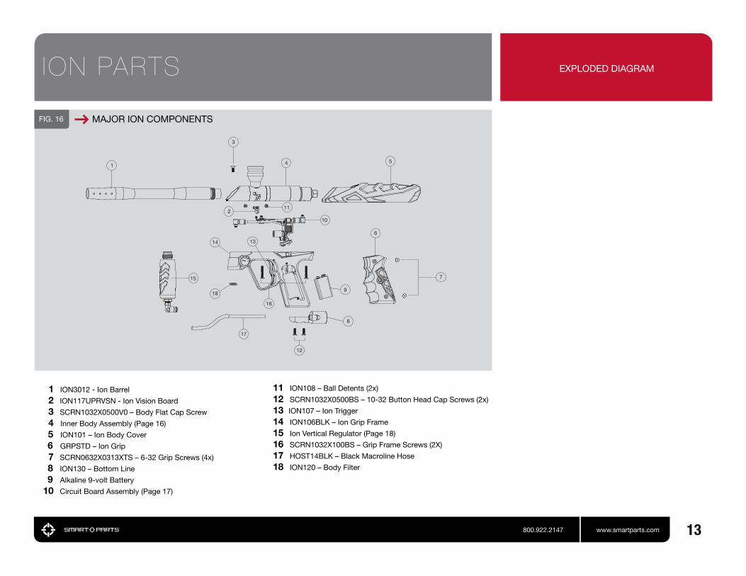
11 ION108 – Ball Detents (2x)
12 SCRN1032X0500BS – 10-32 Button Head Cap Screws (2x)
13 ION107 – Ion Trigger
14 ION106BLK – Ion Grip Frame
15 Ion Vertical Regulator (Page 18)
16 SCRN1032X100BS – Grip Frame Screws (2X)
17 HOST14BLK – Black Macroline Hose
18 ION120 – Body Filter
ION PARTS
1
3
4
6
10
5
7
8
15
211
14
18
16
17
12
13
9
1 ION3012 - Ion Barrel 2 ION117UPRVSN - Ion Vision Board 3 SCRN1032X0500V0 – Body Flat Cap Screw
4 Inner Body Assembly (Page 16)
5 ION101 – Ion Body Cover
6 GRPSTD – Ion Grip 7 SCRN0632X0313XTS – 6-32 Grip Screws (4x)
8 ION130 – Bottom Line
9 Alkaline 9-volt Battery
10 Circuit Board Assembly (Page 17)
13800.922.2147 www.smartparts.com
FIG. 16 MAJOR ION COMPONENTS
EXPLODED DIAGRAM

01 02
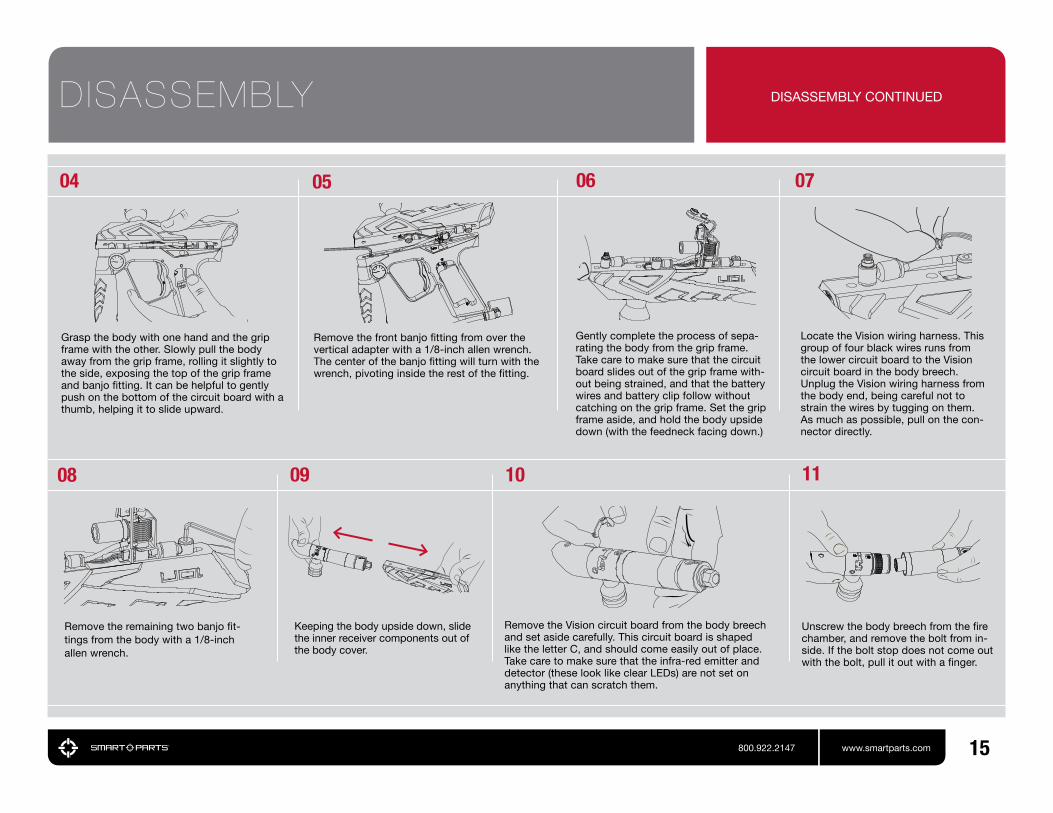
Remove the front and rear grip frame screws using a 1/8-inch allen wrench.
Remove both left side (gauge side) grip screws with a #2 phillips scredwriver and open the flex-ible wraparound grip. Remove the battery from the grip frame. Grasp the battery in one hand and with the other hand grasp the battery clip by the sides and unplug it from the battery. Remove the right side grip screws and the flexible grip, as the upper right grip screw may catch on the circuit board, making its removal difficult.
Do not pull on the battery wires or circuit board to unplug the battery as this may cause signifi-cant damage.
Use a 1/8-inch allen wrench to remove the body flat cap screw which is normally concealed by the barrel.
DISASSEMBLY PLEASE READ CAREFULLY
03Before beginning any maintenance or repair pro-cedures, completely unload and degas the mark-er following the instructions in the Degassing section of this manual. Choose a clean, stable and protected work area where small parts will not be lost, such as a table covered with a towel to prevent parts from rolling. Remove the barrel.
Some Ions may be equipped with a hard remov-able power button, rather than the membrane style power button. During normal maintenance the hard power button does not need to be and should not be removed. If it becomes dam-aged or requires replacement, grip it between a fingernail and thumbnail and wiggle it out, rear side first.
[ CONTINUED ON PAGE 15 ]
14 800.922.2147 www.smartparts.com
REMOVE HARD POWER BUTTONFIG. 17
11
Unscrew the body breech from the fire chamber, and remove the bolt from in-side. If the bolt stop does not come out with the bolt, pull it out with a finger.
Remove the Vision circuit board from the body breech and set aside carefully. This circuit board is shaped like the letter C, and should come easily out of place. Take care to make sure that the infra-red emitter and detector (these look like clear LEDs) are not set on anything that can scratch them.
Keeping the body upside down, slide the inner receiver components out of the body cover.
DISASSEMBLY DISASSEMBLY CONTINUED
Remove the remaining two banjo fit-tings from the body with a 1/8-inch allen wrench.
06
Gently complete the process of sepa-rating the body from the grip frame. Take care to make sure that the circuit board slides out of the grip frame with-out being strained, and that the battery wires and battery clip follow without catching on the grip frame. Set the grip frame aside, and hold the body upside down (with the feedneck facing down.)
07
08
Locate the Vision wiring harness. This group of four black wires runs from the lower circuit board to the Vision circuit board in the body breech. Unplug the Vision wiring harness from the body end, being careful not to strain the wires by tugging on them. As much as possible, pull on the con-nector directly.
10
05
Remove the front banjo fitting from over the vertical adapter with a 1/8-inch allen wrench. The center of the banjo fitting will turn with the wrench, pivoting inside the rest of the fitting.
09
Grasp the body with one hand and the grip frame with the other. Slowly pull the body away from the grip frame, rolling it slightly to the side, exposing the top of the grip frame and banjo fitting. It can be helpful to gently push on the bottom of the circuit board with a thumb, helping it to slide upward.
04
15800.922.2147 www.smartparts.com

01 02 04 05
1 ION102 – Body Breech 2 ION103 – Feed Tube 3 ORN02552070BU – Feed Tube Friction O-Rings (3x) 4 ION109 – Bolt 5 ION11 – Bolt Stop 6 ION104 – Fire Chamber 7 ION110 – Swivel Donut 8 CLP004 – Donut Clip 9 ORN0179OUR – SFT O-Ring 10 ION108 – Ball Detents (2x) 11 ORN117OHN – Rear Breech O-Ring 12 ION117UPRVSN – Vision Circuit Board 13 ORN02270BU – Body Breach Friction O-Ring) 14 ORN02070BU – Body Breech Seal O-Ring 15 ORN0159OUR – Bolt Bumper
REASSEMBLY CLEANING AND REASSEMBLY
Place the bolt stop inside the fire chamber. Make sure the concave side of the bolt stop (shaped like the inside of a cone) faces the back of the marker.
Use SL33K to grease all of the o-rings on the bolt and bolt stop. Apply only a thin coating, do not over-grease.
Make sure the Vision circuit board and its components are clean and undam-aged. Make sure no dirt or debris is blocking the Vision holes in the body breech – use a cotton swab to clean these openings if necessary.
Use a soft cloth to clean all parts of paint and dirt as well as old oil or grease.
03 06Screw the fire chamber into the body breech.
Slide the bolt into the bolt stop inside the fire chamber until it stops.
07 08Reposition the body and grip frame together being careful not to pinch any wires or hoses. Reinstall the grip frame screws, and flat cap body screw, then tighten all three with an 1/8-inch allen wrench. Reinstall the battery, taking care not to pinch the battery wires, and flexible the rubber grip and its screws.
Carefully pass the battery clip down into the grip frame and slide the circuit board into place before reinstalling the forward banjo fitting to its position in the grip frame, again taking care not to cross-thread.
Slide the inner receiver assembly into the body cover while holding both up-side down to prevent the Vision circuit board from falling out, then plug the Vision wire harness back into the Vision circuit board, and reconnect the center and rear banjo fittings to the receiver, being careful not to cross thread them.
Place the Vision circuit board into its slot in the body breech. Its plug should be on the side of the board facing the rear of the marker. The clear emitter and detector should be on the side facing the front of the body breech.If necessary, rotate the swivel donut so that its screw holes are on the bottom of the receiver, lined up with the screw holes in the body breech.
09 10
FIG. 18 INNER BODY ASSEMBLY 16 ORN0162070HN – Bolt Middle O-Ring 17 ORB01070UR – Bolt Rear O-Ring 18 ORN01470UR – Bolt Stop Inner O-Ring 19 ORN02070BU – Bolt Stop Outer O-Ring 20 ORN0157OUR – Swivel Donut O-Rings (2x)
16 800.922.2147 www.smartparts.com

800.922.2147 www.smartparts.com
The solenoid valve is the heart of the Ion. When the circuit board supplies it with power, it redirects gas flow to allow the bolt to close and fire the marker. During normal mainte-nance the solenoid valve should not need to be disassembled. However, if it becomes clogged or develops a leak it is simple to dis-assemble for cleaning or repair.
FIG. 20 SOLENOID EXPLODED VIEW
SOLENOID VALVE DISASSEMBLY AND MAINTENANCE
01 02 04 05Clean the inside of the solenoid with a cotton swab, and clean the armature with a soft cloth, removing any de-bris, oil or grease.
Tip the circuit board over and al-low the armature to fall into your hand. The arma-ture fits loosely in the center of the coil, and should fall out easily.
After the sole-noid bracket is removed, lift the solenoid head straight out, wig-gling if necessary to loosen it.
Follow the disassembly instruc-tions to remove the circuit board from the Ion. Using a 3/32-inch allen wrench, hold the circuit board and solenoid body then pry the bracket from the back of the solenoid valve. Place the wrench between the bracket and the upper, black section of the solenoid valve body.
03 06Replace the solenoid bracket, pressing it back into place. The bent bracket section goes over the bottom side of the solenoid.
A very light layer of SL33K lubri-cating the hose barb will make the installation of new hoses easier, but extreme care must be taken that no excess grease is able to enter the solenoid valve. Holding the solenoid head with a box end or small adjustable wrench over the hose barb will allow the hose to be pulled away from the wrench which will hold back the solenoid head.
Reassemble the solenoid valve. Place the armature back in the coil with the armature facing down.
Push the solenoid head back into the solenoid valve body, making sure that the long hoses and Vision wiring harness are aligned on the same side of the circuit board as the trigger switch.
07
Do not pry against the red solenoid coil or the Blackheart heat shrink coil protector, as this will cause damage.
1 BUM006 – Foam Disk 2 ION118 – Vision Wiring Harness 3 ELB1032X18PTCBNJ – 1/8” Banjo Fitting 4 ELB1032X532PTCBNJ – 4mm Banjo Fitting 5 HOS4MMCLR4025 – 4mm Ion LP Hose 6 EPY117LOVUSASM – Ion Circuit Board 7 HOS4MMCLR875 – 4mm Ion LP Hose 8 ELB1032X532PTCBNJ – 4mm Banjo Fitting 9 Solenoid Armature 10 SOL3UPG – Solenoid Coil 11 Solenoid Head12 Solenoid Bracket13 HOS18CLR1985 – 1/8” Ion LP Hose
17
18 800.922.2147 www.smartparts.com
01 02 03 04
070605
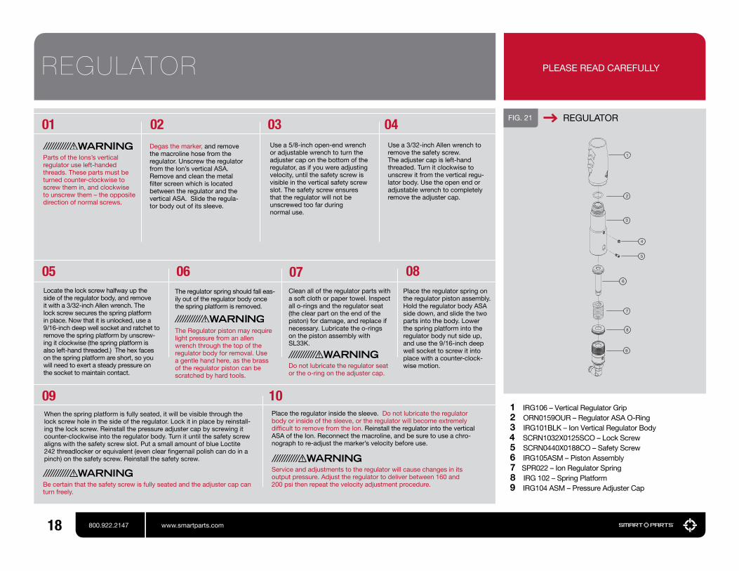
Degas the marker, and remove the macroline hose from the regulator. Unscrew the regulator from the Ion’s vertical ASA. Remove and clean the metal filter screen which is located between the regulator and the vertical ASA. Slide the regula-tor body out of its sleeve.
Use a 5/8-inch open-end wrench or adjustable wrench to turn the adjuster cap on the bottom of the regulator, as if you were adjusting velocity, until the safety screw is visible in the vertical safety screw slot. The safety screw ensures that the regulator will not be unscrewed too far during normal use.
Use a 3/32-inch Allen wrench to remove the safety screw.The adjuster cap is left-hand threaded. Turn it clockwise to unscrew it from the vertical regu-lator body. Use the open end or adjustable wrench to completely remove the adjuster cap.
Locate the lock screw halfway up the side of the regulator body, and remove it with a 3/32-inch Allen wrench. The lock screw secures the spring platform in place. Now that it is unlocked, use a 9/16-inch deep well socket and ratchet to remove the spring platform by unscrew-ing it clockwise (the spring platform is also left-hand threaded.) The hex faces on the spring platform are short, so you will need to exert a steady pressure on the socket to maintain contact.
The regulator spring should fall eas-ily out of the regulator body once the spring platform is removed.
The Regulator piston may require light pressure from an allen wrench through the top of the regulator body for removal. Use a gentle hand here, as the brass of the regulator piston can be scratched by hard tools.
Clean all of the regulator parts with a soft cloth or paper towel. Inspect all o-rings and the regulator seat (the clear part on the end of the piston) for damage, and replace if necessary. Lubricate the o-rings on the piston assembly with SL33K.
Do not lubricate the regulator seat or the o-ring on the adjuster cap.
08
09 10When the spring platform is fully seated, it will be visible through the lock screw hole in the side of the regulator. Lock it in place by reinstall-ing the lock screw. Reinstall the pressure adjuster cap by screwing it counter-clockwise into the regulator body. Turn it until the safety screw aligns with the safety screw slot. Put a small amount of blue Loctite 242 threadlocker or equivalent (even clear fingernail polish can do in a pinch) on the safety screw. Reinstall the safety screw.
Place the regulator spring on the regulator piston assembly. Hold the regulator body ASA side down, and slide the two parts into the body. Lower the spring platform into the regulator body nut side up, and use the 9/16-inch deep well socket to screw it into place with a counter-clock-wise motion.
Parts of the Ions’s vertical regulator use left-handed threads. These parts must be turned counter-clockwise to screw them in, and clockwise to unscrew them – the opposite direction of normal screws.
FIG. 21 REGULATOR
1 IRG106 – Vertical Regulator Grip 2 ORN0159OUR – Regulator ASA O-Ring 3 IRG101BLK – Ion Vertical Regulator Body 4 SCRN1032X0125SCO – Lock Screw 5 SCRN0440X0188CO – Safety Screw 6 IRG105ASM – Piston Assembly 7 SPR022 – Ion Regulator Spring 8 IRG 102 – Spring Platform 9 IRG104 ASM – Pressure Adjuster Cap
REGULATOR
Service and adjustments to the regulator will cause changes in its output pressure. Adjust the regulator to deliver between 160 and 200 psi then repeat the velocity adjustment procedure.Be certain that the safety screw is fully seated and the adjuster cap can
turn freely.
Place the regulator inside the sleeve. Do not lubricate the regulator body or inside of the sleeve, or the regulator will become extremely difficult to remove from the Ion. Reinstall the regulator into the vertical ASA of the Ion. Reconnect the macroline, and be sure to use a chro-nograph to re-adjust the marker’s velocity before use.
PLEASE READ CAREFULLY

19800.922.2147 www.smartparts.com
01 02 03 04 05FIG. 22 PRYING OUT DETENT
BALL DETENTS INSPECTION, CLEANING AND REPLACEMENT
Reassemble the marker.Reinstall the detents by pressing them into place with a thumb.
Reach a finger into the body breech and press out against the detent. It may then be removed by prying or gripping with fingernails, needle-nosed pliers, an o-ring pick or even a 0.050-inch allen wrench. Inspect the ball detents for tears or damage. If they are damaged, replace them. If not, clean them with a soft cloth, and clean the detent openings in the body breech with a cotton swab.
Look into the body breech. The tip of each ball detent should extend approxi-mately 1/16 of an inch into the breech area. If either detent does not reach this far into the breech, it should be replaced.
To avoid risk of eye injury, even while wearing goggles, do not look into the barrel or breech of an assembled marker.
Degas and disassem-ble the marker (see disassembly section.)
20 800.922.2147 www.smartparts.com
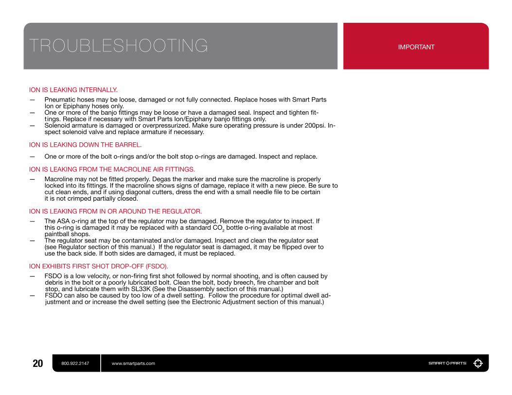
ION IS LEAKING INTERNALLY.
— Pneumatic hoses may be loose, damaged or not fully connected. Replace hoses with Smart Parts Ion or Epiphany hoses only.
— One or more of the banjo fittings may be loose or have a damaged seal. Inspect and tighten fit- t ings. Replace if necessary with Smart Parts Ion/Epiphany banjo fittings only.
— Solenoid armature is damaged or overpressurized. Make sure operating pressure is under 200psi. In-spect solenoid valve and replace armature if necessary.
ION IS LEAKING DOWN THE BARREL.
— One or more of the bolt o-rings and/or the bolt stop o-rings are damaged. Inspect and replace.
ION IS LEAKING FROM THE MACROLINE AIR FITTINGS.
— Macroline may not be fitted properly. Degas the marker and make sure the macroline is properly locked into its fittings. If the macroline shows signs of damage, replace it with a new piece. Be sure to cut clean ends, and if using diagonal cutters, dress the end with a small needle file to be certain it is not crimped partially closed.
ION IS LEAKING FROM IN OR AROUND THE REGULATOR.
— The ASA o-ring at the top of the regulator may be damaged. Remove the regulator to inspect. If this o-ring is damaged it may be replaced with a standard CO2 bottle o-ring available at most paintball shops.
— The regulator seat may be contaminated and/or damaged. Inspect and clean the regulator seat (see Regulator section of this manual.) If the regulator seat is damaged, it may be flipped over to use the back side. If both sides are damaged, it must be replaced.
ION EXHIBITS FIRST SHOT DROP-OFF (FSDO).
— FSDO is a low velocity, or non-firing first shot followed by normal shooting, and is often caused by debris in the bolt or a poorly lubricated bolt. Clean the bolt, body breech, fire chamber and bolt stop, and lubricate them with SL33K (See the Disassembly section of this manual.)— FSDO can also be caused by too low of a dwell setting. Follow the procedure for optimal dwell ad- justment and or increase the dwell setting (see the Electronic Adjustment section of this manual.)
TROUBLESHOOTING IMPORTANT
21800.922.2147 www.smartparts.com
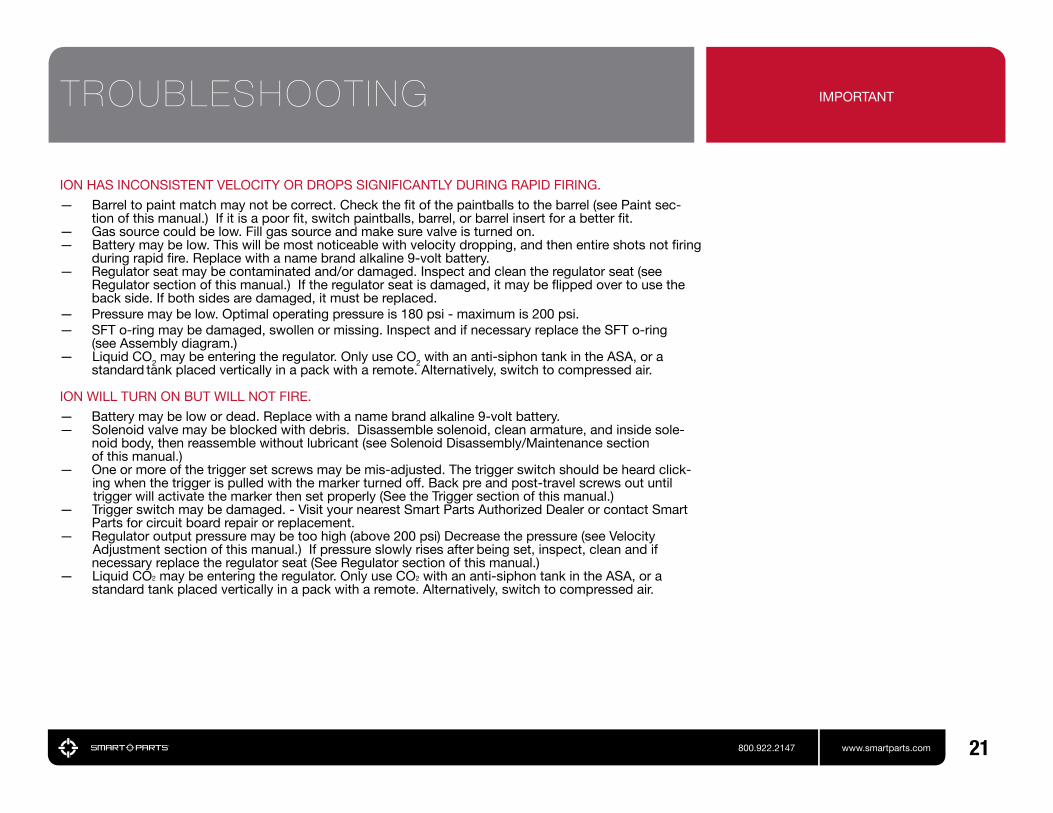
ION HAS INCONSISTENT VELOCITY OR DROPS SIGNIFICANTLY DURING RAPID FIRING.
— Barrel to paint match may not be correct. Check the fit of the paintballs to the barrel (see Paint sec- tion of this manual.) If it is a poor fit, switch paintballs, barrel, or barrel insert for a better fit.
— Gas source could be low. Fill gas source and make sure valve is turned on.— Battery may be low. This will be most noticeable with velocity dropping, and then entire shots not firing
during rapid fire. Replace with a name brand alkaline 9-volt battery.— Regulator seat may be contaminated and/or damaged. Inspect and clean the regulator seat (see
Regulator section of this manual.) If the regulator seat is damaged, it may be flipped over to use the back side. If both sides are damaged, it must be replaced.
— Pressure may be low. Optimal operating pressure is 180 psi - maximum is 200 psi.— SFT o-ring may be damaged, swollen or missing. Inspect and if necessary replace the SFT o-ring
(see Assembly diagram.)— Liquid CO2 may be entering the regulator. Only use CO2 with an anti-siphon tank in the ASA, or a
standard tank placed vertically in a pack with a remote. Alternatively, switch to compressed air.
ION WILL TURN ON BUT WILL NOT FIRE.
— Battery may be low or dead. Replace with a name brand alkaline 9-volt battery.— Solenoid valve may be blocked with debris. Disassemble solenoid, clean armature, and inside sole-
noid body, then reassemble without lubricant (see Solenoid Disassembly/Maintenance section of this manual.)
— One or more of the trigger set screws may be mis-adjusted. The trigger switch should be heard click- ing when the trigger is pulled with the marker turned off. Back pre and post-travel screws out until trigger will activate the marker then set properly (See the Trigger section of this manual.)— Trigger switch may be damaged. - Visit your nearest Smart Parts Authorized Dealer or contact Smart Parts for circuit board repair or replacement.— Regulator output pressure may be too high (above 200 psi) Decrease the pressure (see Velocity Adjustment section of this manual.) If pressure slowly rises after being set, inspect, clean and if
necessary replace the regulator seat (See Regulator section of this manual.)— Liquid CO2 may be entering the regulator. Only use CO2 with an anti-siphon tank in the ASA, or a
standard tank placed vertically in a pack with a remote. Alternatively, switch to compressed air.
TROUBLESHOOTING IMPORTANT

22 800.922.2147 www.smartparts.com
ION’S POWER BUTTON LIGHT FLASHES IN VISION MODE BUT WILL NOT FIRE.
— Possible chamber obstruction. Hold the power button down to put the marker into non-Vision mode. While wearing paintball mask/googles in an area where it is safe to fire, fire the marker to clear any possible chamber obstructions.— Paint or debris may be blocking the Vision eye from “seeing” the breech. Remove the Vision circuit board. Carefully clean the infrared emitter and detector with a damp, soft cloth and clean the Vision ports in the body breech with a cotton swab (see Disassembly section of this manual.)— Wiring harness may be disconnected. Check to make sure that the wiring harness running from the solenoid circuit board in the grip frame to the Vision circuit board in the body is plugged in at both ends, and is not bent, crimped, broken or frayed (See Disassembly section of this manual.)— Vision reflector may be damaged or missing. Inside of polymer Ion body covers on the right hand side is a reflective mylar sticker. This sticker must be clean and intact for proper Vision operation.
THE ION IS BREAKING PAINT.
— Battery may be low or dead. Replace with a name brand 9-volt alkaline battery.— Ball detents may be worn or damaged. Inspect and if necessary replace (See Ball Detent section of this manual.)— Barrel to paint match may not be correct. Check the fit of the paintballs to the barrel (see Paint section of this manual.) If it is a poor fit, switch paintballs, barrel, or barrel insert for a better fit.— Dwell setting may be too high. Lower the dwell setting in three click increments and retest, or reset to the optimum dwell value (see the Dwell section of this manual.)— Vision mode may be turned off. This will be indicated by a double-blink pattern on the power button. Turn Vision on by pressing the power button.— Paint or debris may be partially blocking the Vision eye from properly “seeing” the breech. Remove the Vision circuit board. Carefully clean the infrared emitter and detector with a damp, soft cloth and clean the Vision ports in the body breech with a cotton swab (see Disassembly section of this manual.)— Vision reflector may be damaged or missing. Inside of plastic body covers, on the right hand side is a reflective mylar sticker. This sticker must be clean and intact for proper Vision operation.— Wiring harness may be damaged. Check to make sure that the wiring harness running from the sole- noid circuit board in the grip frame to the Vision circuit board in the body is plugged in at both ends, and is not bent, crimped, broken or frayed (See Disassembly section of this manual.)— Vision board may be damaged from improper installation. Replace Vision board (See Disassembly section of this manual.)— Liquid CO2 may be entering the regulator. Only use CO2 with an anti-siphon tank in the ASA, or a standard tank placed vertically in a pack with a remote. Alternatively, switch to compressed air.
TROUBLESHOOTING IMPORTANT
23800.922.2147 www.smartparts.com
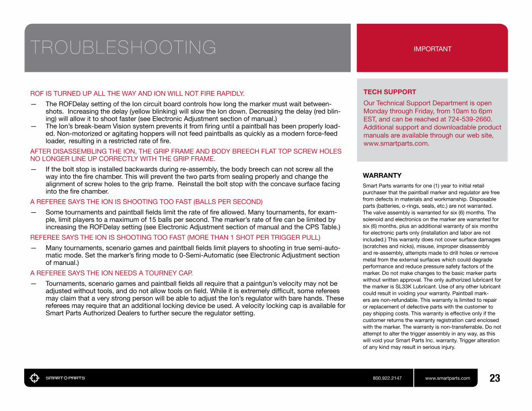
TECH SUPPORT
Our Technical Support Department is open Monday through Friday, from 10am to 6pm EST, and can be reached at 724-539-2660. Additional support and downloadable product manuals are available through our web site, www.smartparts.com.
ROF IS TURNED UP ALL THE WAY AND ION WILL NOT FIRE RAPIDLY.
— The ROFDelay setting of the Ion circuit board controls how long the marker must wait between-shots. Increasing the delay (yellow blinking) will slow the Ion down. Decreasing the delay (red blin-ing) will allow it to shoot faster (see Electronic Adjustment section of manual.)
— The Ion’s break-beam Vision system prevents it from firing until a paintball has been properly load-ed. Non-motorized or agitating hoppers will not feed paintballs as quickly as a modern force-feed loader, resulting in a restricted rate of fire.
AFTER DISASSEMBLING THE ION, THE GRIP FRAME AND BODY BREECH FLAT TOP SCREW HOLES NO LONGER LINE UP CORRECTLY WITH THE GRIP FRAME.
— If the bolt stop is installed backwards during re-assembly, the body breech can not screw all the way into the fire chamber. This will prevent the two parts from sealing properly and change the alignment of screw holes to the grip frame. Reinstall the bolt stop with the concave surface facing into the fire chamber.
A REFEREE SAYS THE ION IS SHOOTING TOO FAST (BALLS PER SECOND)
— Some tournaments and paintball fields limit the rate of fire allowed. Many tournaments, for exam- ple, limit players to a maximum of 15 balls per second. The marker’s rate of fire can be limited by increasing the ROFDelay setting (see Electronic Adjustment section of manual and the CPS Table.)
REFEREE SAYS THE ION IS SHOOTING TOO FAST (MORE THAN 1 SHOT PER TRIGGER PULL)
— Many tournaments, scenario games and paintball fields limit players to shooting in true semi-auto-matic mode. Set the marker’s firing mode to 0-Semi-Automatic (see Electronic Adjustment section of manual.)
A REFEREE SAYS THE ION NEEDS A TOURNEY CAP.
— Tournaments, scenario games and paintball fields all require that a paintgun’s velocity may not be adjusted without tools, and do not allow tools on field. While it is extremely difficult, some referees may claim that a very strong person will be able to adjust the Ion’s regulator with bare hands. These referees may require that an additional locking device be used. A velocity locking cap is available for Smart Parts Authorized Dealers to further secure the regulator setting.
WARRANTYSmart Parts warrants for one (1) year to initial retail purchaser that the paintball marker and regulator are free from defects in materials and workmanship. Disposable parts (batteries, o-rings, seals, etc.) are not warranted. The valve assembly is warranted for six (6) months. The solenoid and electronics on the marker are warranted for six (6) months, plus an additional warranty of six months for electronic parts only (installation and labor are not included.) This warranty does not cover surface damages (scratches and nicks), misuse, improper disassembly and re-assembly, attempts made to drill holes or remove metal from the external surfaces which could degrade performance and reduce pressure safety factors of the marker. Do not make changes to the basic marker parts without written approval. The only authorized lubricant for the marker is SL33K Lubricant. Use of any other lubricant could result in voiding your warranty. Paintball mark-ers are non-refundable. This warranty is limited to repair or replacement of defective parts with the customer to pay shipping costs. This warranty is effective only if the customer returns the warranty registration card enclosed with the marker. The warranty is non-transferrable. Do not attempt to alter the trigger assembly in any way, as this will void your Smart Parts Inc. warranty. Trigger alteration of any kind may result in serious injury.
TROUBLESHOOTING IMPORTANT
24 800.922.2147 www.smartparts.com
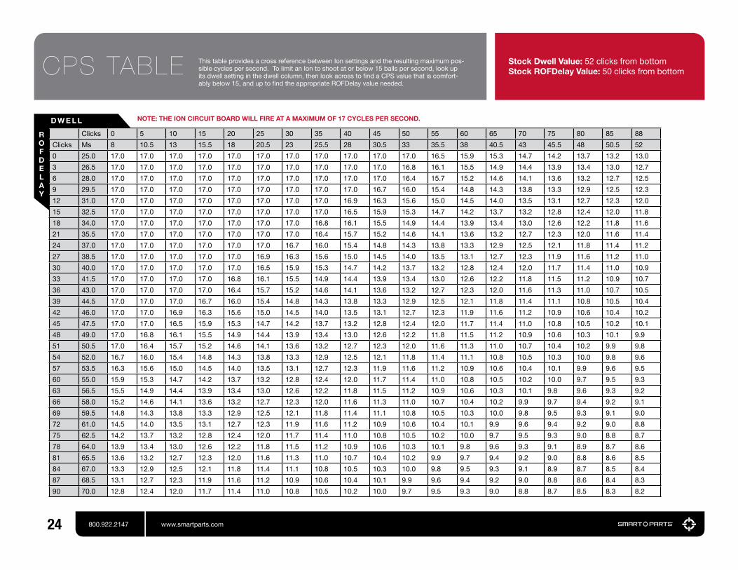
Clicks 0 5 10 15 20 25 30 35 40 45 50 55 60 65 70 75 80 85 88
Clicks Ms 8 10.5 13 15.5 18 20.5 23 25.5 28 30.5 33 35.5 38 40.5 43 45.5 48 50.5 52
0 25.0 17.0 17.0 17.0 17.0 17.0 17.0 17.0 17.0 17.0 17.0 17.0 16.5 15.9 15.3 14.7 14.2 13.7 13.2 13.0
3 26.5 17.0 17.0 17.0 17.0 17.0 17.0 17.0 17.0 17.0 17.0 16.8 16.1 15.5 14.9 14.4 13.9 13.4 13.0 12.7
6 28.0 17.0 17.0 17.0 17.0 17.0 17.0 17.0 17.0 17.0 17.0 16.4 15.7 15.2 14.6 14.1 13.6 13.2 12.7 12.5
9 29.5 17.0 17.0 17.0 17.0 17.0 17.0 17.0 17.0 17.0 16.7 16.0 15.4 14.8 14.3 13.8 13.3 12.9 12.5 12.3
12 31.0 17.0 17.0 17.0 17.0 17.0 17.0 17.0 17.0 16.9 16.3 15.6 15.0 14.5 14.0 13.5 13.1 12.7 12.3 12.0
15 32.5 17.0 17.0 17.0 17.0 17.0 17.0 17.0 17.0 16.5 15.9 15.3 14.7 14.2 13.7 13.2 12.8 12.4 12.0 11.8
18 34.0 17.0 17.0 17.0 17.0 17.0 17.0 17.0 16.8 16.1 15.5 14.9 14.4 13.9 13.4 13.0 12.6 12.2 11.8 11.6
21 35.5 17.0 17.0 17.0 17.0 17.0 17.0 17.0 16.4 15.7 15.2 14.6 14.1 13.6 13.2 12.7 12.3 12.0 11.6 11.4
24 37.0 17.0 17.0 17.0 17.0 17.0 17.0 16.7 16.0 15.4 14.8 14.3 13.8 13.3 12.9 12.5 12.1 11.8 11.4 11.2
27 38.5 17.0 17.0 17.0 17.0 17.0 16.9 16.3 15.6 15.0 14.5 14.0 13.5 13.1 12.7 12.3 11.9 11.6 11.2 11.0
30 40.0 17.0 17.0 17.0 17.0 17.0 16.5 15.9 15.3 14.7 14.2 13.7 13.2 12.8 12.4 12.0 11.7 11.4 11.0 10.9
33 41.5 17.0 17.0 17.0 17.0 16.8 16.1 15.5 14.9 14.4 13.9 13.4 13.0 12.6 12.2 11.8 11.5 11.2 10.9 10.7
36 43.0 17.0 17.0 17.0 17.0 16.4 15.7 15.2 14.6 14.1 13.6 13.2 12.7 12.3 12.0 11.6 11.3 11.0 10.7 10.5
39 44.5 17.0 17.0 17.0 16.7 16.0 15.4 14.8 14.3 13.8 13.3 12.9 12.5 12.1 11.8 11.4 11.1 10.8 10.5 10.4
42 46.0 17.0 17.0 16.9 16.3 15.6 15.0 14.5 14.0 13.5 13.1 12.7 12.3 11.9 11.6 11.2 10.9 10.6 10.4 10.2
45 47.5 17.0 17.0 16.5 15.9 15.3 14.7 14.2 13.7 13.2 12.8 12.4 12.0 11.7 11.4 11.0 10.8 10.5 10.2 10.1
48 49.0 17.0 16.8 16.1 15.5 14.9 14.4 13.9 13.4 13.0 12.6 12.2 11.8 11.5 11.2 10.9 10.6 10.3 10.1 9.9
51 50.5 17.0 16.4 15.7 15.2 14.6 14.1 13.6 13.2 12.7 12.3 12.0 11.6 11.3 11.0 10.7 10.4 10.2 9.9 9.8
54 52.0 16.7 16.0 15.4 14.8 14.3 13.8 13.3 12.9 12.5 12.1 11.8 11.4 11.1 10.8 10.5 10.3 10.0 9.8 9.6
57 53.5 16.3 15.6 15.0 14.5 14.0 13.5 13.1 12.7 12.3 11.9 11.6 11.2 10.9 10.6 10.4 10.1 9.9 9.6 9.5
60 55.0 15.9 15.3 14.7 14.2 13.7 13.2 12.8 12.4 12.0 11.7 11.4 11.0 10.8 10.5 10.2 10.0 9.7 9.5 9.3
63 56.5 15.5 14.9 14.4 13.9 13.4 13.0 12.6 12.2 11.8 11.5 11.2 10.9 10.6 10.3 10.1 9.8 9.6 9.3 9.2
66 58.0 15.2 14.6 14.1 13.6 13.2 12.7 12.3 12.0 11.6 11.3 11.0 10.7 10.4 10.2 9.9 9.7 9.4 9.2 9.1
69 59.5 14.8 14.3 13.8 13.3 12.9 12.5 12.1 11.8 11.4 11.1 10.8 10.5 10.3 10.0 9.8 9.5 9.3 9.1 9.0
72 61.0 14.5 14.0 13.5 13.1 12.7 12.3 11.9 11.6 11.2 10.9 10.6 10.4 10.1 9.9 9.6 9.4 9.2 9.0 8.8
75 62.5 14.2 13.7 13.2 12.8 12.4 12.0 11.7 11.4 11.0 10.8 10.5 10.2 10.0 9.7 9.5 9.3 9.0 8.8 8.7
78 64.0 13.9 13.4 13.0 12.6 12.2 11.8 11.5 11.2 10.9 10.6 10.3 10.1 9.8 9.6 9.3 9.1 8.9 8.7 8.6
81 65.5 13.6 13.2 12.7 12.3 12.0 11.6 11.3 11.0 10.7 10.4 10.2 9.9 9.7 9.4 9.2 9.0 8.8 8.6 8.5
84 67.0 13.3 12.9 12.5 12.1 11.8 11.4 11.1 10.8 10.5 10.3 10.0 9.8 9.5 9.3 9.1 8.9 8.7 8.5 8.4
87 68.5 13.1 12.7 12.3 11.9 11.6 11.2 10.9 10.6 10.4 10.1 9.9 9.6 9.4 9.2 9.0 8.8 8.6 8.4 8.3
90 70.0 12.8 12.4 12.0 11.7 11.4 11.0 10.8 10.5 10.2 10.0 9.7 9.5 9.3 9.0 8.8 8.7 8.5 8.3 8.2
D W E L L
ROFDELAY
NOTE: THE EPIPHANY CIRCUIT BOARD WILL NOT FIRE AT RATES ABOVE 17 CYCLES PER SECOND.
CPS TABLE Stock Dwell Value: 52 clicks from bottomStock ROFDelay Value: 50 clicks from bottom
This table provides a cross reference between Ion settings and the resulting maximum pos-sible cycles per second. To limit an Ion to shoot at or below 15 balls per second, look up its dwell setting in the dwell column, then look across to find a CPS value that is comfort-ably below 15, and up to find the appropriate ROFDelay value needed.
NOTE: THE ION CIRCUIT BOARD WILL FIRE AT A MAXIMUM OF 17 CYCLES PER SECOND.

800.922.2147 100 Station St. Loyalhanna, PA 15661 www.smartparts.com manual version 2.0