INSTRUCTION MANUAL INSTRUCTIVO DE OPERACION, CENTROS … · DEWALT heavy duty industrial tools are...
18
INSTRUCTION MANUAL GUIDE D'UTILISATION MANUAL DE INSTRUCCIONES INSTRUCTIVO DE OPERACION, CENTROS DE SERVIClO Y POLIZA DE GARANTiA. ADVERTENClA: LEASE ESTE INSTRUCTIVO ANTES DE USAR EL PRODUCTO. ® DW897/DW897-220 16 Gauge Nibbler Grignoteuse de calibre 16 Cortadora de lamina calibre 16
Transcript of INSTRUCTION MANUAL INSTRUCTIVO DE OPERACION, CENTROS … · DEWALT heavy duty industrial tools are...

INSTRUCTION MANUALGUIDE D'UTILISATIONMANUAL DE INSTRUCCIONES
INSTRUCTIVO DE OPERACION, CENTROS DE SERVIClO Y POLIZADE GARANTiA. ADVERTENClA: LEASE ESTE INSTRUCTIVO ANTESDE USAR EL PRODUCTO.
®DW897/DW897-22016 Gauge NibblerGrignoteuse de calibre 16Cortadora de lamina calibre 16

IF YOU HAVE ANY QUESTIONS OR COMMENTS ABOUT THISOR ANY DEWALT TOOL, CALL US TOLL FREE AT:
1-800-4-DEWALT (1-800-433-9258)
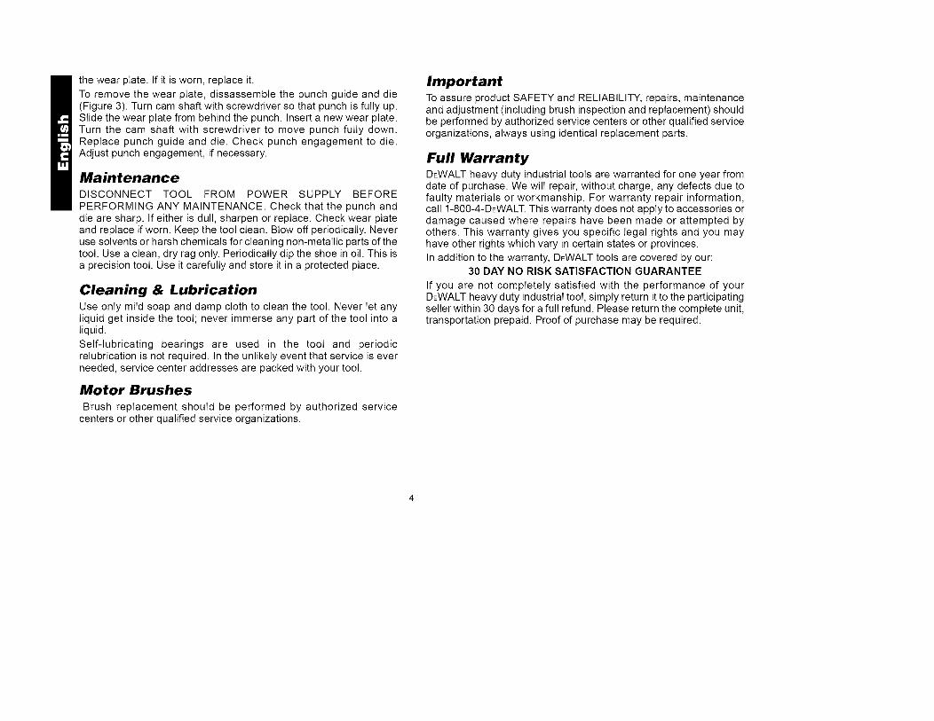
HEAD
PUNCH--
--PUNCHGUIDE
\i SWITCHLOCK
PADDLESWITCH BUTTON
ISHOE DW897/DW897-22016-Gauge
ProfileNibbler
IMPORTANT SAFETYINSTRUCTIONS (FOR ALL TOOLS)
z_ WARNING: When using electric tools, basic safety precautionsshould always be followed to reduce risk of fire, electric shock, andpersonal injury, including the following:
READ ALL INSTRUCTIONS
Double InsulationDouble insulated tools are constructed throughout with two separatelayers of electrical insulation or one double thickness of insulationbetween you and the tool's electrical system. Tools built with thisinsulation system are not intended to be grounded. As a result, yourtool is equipped with a two prong plug which permits you to useextension cords without concern for maintaining a groundconnection.
NOTE: Double insulation does not take the place of normal safetyprecautions when operating this tool. The insulation system is foradded protection against injury resulting from a possible electricalinsulation failure within the tool.z_ CAUTION: WHEN SERVICING USE ONLY IDENTICAL RE-
PLACEMENT PARTS. Repair or replace damaged cords.
Polarized Plugs(DW897)Polarized plugs (one blade is wider than the other) are used onequipment to reduce the risk of electric shock. When provided, thisplug will fit into a polarized outlet only one way. If the plug does notfit fully into the outlet, reverse the plug. If it still does not fit, contact aqualified electrician to install the proper outlet. Do not change theplug in any way.

For All Tools:• KEEP WORK AREA CLEAN. Cluttered areas and benches invite
injuries.• CONSIDER WORK AREA ENVIRONMENT. Don't expose power
tools to rain. Don't use power tools in damp or wet locations. Keepwork area well lit.
• GUARD AGAINST ELECTRIC SHOCK. Prevent body contactwith grounded surfaces; for example, pipes, radiators, ranges,and refrigerator enclosures.
• KEEP CHILDREN AWAY. All visitors should be kept away fromwork area. Do not let visitors contact tool or extension cord.
• STORE IDLE TOOLS. When not in use, tools should be stored indry, and high or locked-up place -- out of reach of children.
• DON'T FORCE A TOOL. It will do the job better and safer at therate for which it was intended.
• USE RIGHT TOOL. Don't force small tool or attachment to do thejob of a heavy duty tool Don't use tool for purpose not intended; forexample, don't use circular saw for cutting tree limbs or logs.
• DRESS PROPERLY. Do not wear loose clothing or jewelry. Theycan be caught in moving parts. Rubber gloves and non-skidfootwear are recommended when working outdoors. Wearprotective hair covering to contain long hair.
• USE SAFETY GLASSES. Also use face or dustmask if operationis dusty
• DON'T ABUSE CORD. Never carry tool by cord or yank it todisconnect from receptacle. Keep cord from heat, oil, and sharpedges.
• SECURE WORK. Use clamps or a vise to hold work. It's safer thanusing your hand and it frees both hands to operate tool
• DON'T OVERREACH. Keep proper footing and balance at alltimes.
• MAINTAIN TOOLS WITH CARE. Keep tools sharp and clean forbetter and safe performance. Follow instructions for lubricating andchanging accessories. Inspect tool cords periodically and if
damaged have repaired by authorized service facility. Inspectextension cords periodically and replace if damaged. Keephandles dry, clean, and free from oil and grease.DISCONNECT OR LOCK OFF TOOLS when not in use, beforeservicing, and when changing accessories, such as blades, bits,cutters.REMOVE ADJUSTING KEYS AND WRENCHES. Form habit ofchecking to see that keys and adjusting wrenches are removedfrom tool before turning it on.AVOID UNINTENTIONAL STARTING. Don't carry plugged-in toolwith finger on the switch. Be sure the switch is off when pluggingin.
EXTENSION CORDS. Make sure your extension cord is in goodcondition. When using an extension cord, be sure to use oneheavy enough to carry the current your product will draw. Anundersized cord will cause a drop in line voltage resulting in lossof power and overheating. The following table shows the correctsize to use depending on cord length and nameplate ampererating. If in doubt, use the next heavier gage. The smaller the gagenumber, the heavier the cord.
MinimumGage for Cord SetsVolts120V240VAmpere RatingMore Not moreThan Than0 66 1010 1212 16
Total Length of Cord in Feet0-25 26-50 51-100 101-1500-50 51-100 101-200 201-300
AWG
18 16 16 1418 16 14 1216 16 14 1214 12 Not Recommended
STAY ALERT. Watch what you are doing. Use common sense.Do not operate tool when you are tired.OUTDOOR USE EXTENSION CORDS. When tool is usedoutdoors, use only extension cords intended for use outdoors andso marked.

• CHECKDAMAGEDPARTS.Beforefurtheruseofthetool,aguardor other part that is damaged should be carefully checkedto determine that it will operate properly and perform its intendedfunction. Check for alignment of moving parts, binding of movingparts, breakage of parts, mounting, and any other conditions thatmay affect its operation. A guard or other part that is defectiveshould be properly repaired or replaced by an authorized servicecenter unless otherwise indicated elsewhere in this instructionmanual. Have defective switches replaced by authorized servicecenter. Do not use tool if switch does not turn it on and off.
• DO NOT OPERATE portable electric tools near flammable liquidsor in gaseous or explosive atmospheres. Motors in these toolsnormally spark, and the sparks might ignite fumes.
• CAUTION: When drilling or driving into walls, floors or whereverfive electrical wires may be encountered, DO NOT TOUCH ANYMETAL PARTS OF THE TOOLS! Hold the tool only by insulatedgrasping surfaces to prevent electric shock if you drive into a livewire.
SAVE THESE INSTRUCTIONSFOR FUTURE USE
Operating Rules for Nibblers1. Always wear safety glasses and protective gloves.2. Wear safety shoes to protect your feet from sharp metal debris on
floor.3. Cut material at or below rated capacity. Remember, material
thickness increases as gauge number decreases (14 gauge isthicker than 16 gauge). 14 gauge thickness is .075" (1,9 mm); 16gauge is. 060" (1,5 mm).
4. Keep all screws tight. Periodically check them for loosening.5. Unplug tool before making any adjustments.6. Do not put anything into a motor housing opening.
7. Keep tool clean. Blow off.any metal debris and dirt from tool8. Firmly secure the piece of metal to be cut to prevent movement
during cutting.
PADDLE SWITCHTo start the tool, depress the paddle switch. To turn the tool off,release the paddle. The switch can be locked on be engaging thelock button located near the rear of the tool while holding the paddledepressed. Always be sure that the tool is not locked on beforeplugging it in. To turn the tool off when it is locked on, squeeze andrelease the paddle once.
OperationTURN OFF TOOL AND DISCONNECT FROM POWER SUPPLY
BEFORE MAKING ANY ADJUSTMENTS. Always wear safetyglasses and protective gloves.
Lubricate surface of material with oil. The profile nibbler is designedto cut corrugated, flat, and box steel forms.
The tool is factory assembled with the punch oriented forward forcutting flat and shallow corrugated material. To cut deeper corrugatedmetals and box sections, rotate the head 90 °to either side to use toolsideways.
The shoe can be aligned in three positions: left, forward, and right.(See Figure 2).
To rotate the head, loosen the set screw. Turn the head in the desireddirection. NOTE: Do not rotate the head in a complete circle as thiswill change the punch engagement in the die.
Rotate the shoe and turn the set screw in until you feel the set screwengage a recess in the shoe. Tighten the set screw firmly.Periodically recheck this screw for tightness.
Sharpening PunchesNever cut with a blunt, dull punch or die. Punches can be sharpened

upto1/8"(3mm).Toremovethepunch,loosentheheadsetscrewabout4-5turns(SeeFigure2).Slidetheshoeassemblyfromthehead.Unscrewthepunchfromtheconnectingrodbushing.Punchmayberesharpenedcarefullyona benchgrinderwithafinegritwheel.Becarefulthatthepunchdoesnotbecomeshorterthantheminimumlengthof2.44inches(2-7/16inchesor61mm).Punchesshorterthanthiswillnotengagethediesufficientlyandmustbereplaced.Thegroundfacemustbesquaretothepunchaxis.Aftergrinding,carefullystonethegroundedgestoremoveburrs.Donotroundovercorners.
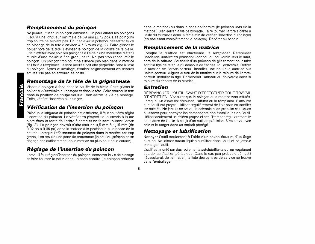
Figure2 Figure3
HEAD HEAD CAM_ SHAFT
Reassembly of Nibbler HeadScrew the punch fully into the connecting rod bushing. Slide the shoeassembly over the end of the punch and into the head. NOTE:Lubrication groove in punch face must not be exposed at front ofshoe. Turn the shoe to desired cut orientation. Tighten set screw.Next, check punch engagement.
Checking Punch EngagementSince the punch length is now changed, the punch engagement mayhave to be adjusted. Check punch engagement by placing a flatblade screwdriver in the cam shaft slot and turning the shaft. (SeeFigure 2) Punch should dip .020" to .04" (.5 to 1.0mm) into the die atthe full down stroke position. Too much punch dip into the die willresult in a loss of capacity (bottom of punch will not clear die enoughon up stroke.)
SHAFT Punch Engagement AdjustmentIf the punch engagement should need adjustment, loosen the setscrew and rotate shoe either clockwise (punch deeper into die) orcounterclockwise (punch out of die). Tighten set screw firmly. Turncam shaft with screwdriver in slot to check punch engagement(moving punch fully down). Repeat as necessary.
CONNECTING SETRODBUSHING SCREW PUNCH
--DIE SHOE--i DIE
PUNCH I WEARGUIDE SHOE PLATE
Die ReplacementIf the die becomes dull, replace it. Replace old die by removing twoscrews at the front (Figure 2). Install new die and tighten screws.Recheck punch engagement and adjust punch depth if necessary.
Wear Plate
This tool is equipped with a wear plate to increase the life of theshoe (See Figure 3). The wear plate fits between the shoe and thepunch. Anytime the punch, punch guide or die is removed, inspect
thewearplate.Ifit isworn,replaceit.Toremovethewearplate,dissassembtethepunchguideanddie(Figure3).Turncamshaftwithscrewdriversothatpunchisfullyup.Slidethewearplatefrombehindthepunch.Insertanewwearplate.Turnthecamshaftwithscrewdriverto movepunchfullydown.Replacepunchguideanddie.Checkpunchengagementtodie.Adjustpunchengagement,ifnecessary.
MaintenanceDISCONNECT TOOL FROM POWER SUPPLY BEFOREPERFORMING ANY MAINTENANCE. Check that the punch anddie are sharp. If either is dull, sharpen or replace. Check wear plateand replace if worn. Keep the tool clean. Blow off periodically. Neveruse solvents or harsh chemicals for cleaning non-metallic parts of thetool. Use a clean, dry rag only. Periodically dip the shoe in oil. This isa precision tool. Use it carefully and store it in a protected place.
Cleaning & LubricationUse only mild soap and damp cloth to clean the tool. Never let anyliquid get inside the tool; never immerse any part of the tool into aliquid.
Self-lubricating bearings are used in the tool and periodicrelubrication is not required. In the unlikely event that service is everneeded, service center addresses are packed with your tool.
Motor Brushes
Brush replacement should be performed by authorized servicecenters or other qualified service organizations.
ImportantTo assure product SAFETY and RELIABILITY, repairs, maintenanceand adjustment (including brush inspection and replacement) shouldbe performed by authorized service centers or other qualified serviceorganizations, always using identical replacement parts.
Full WarrantyDEWALT heavy duty industrial tools are warranted for one year fromdate of purchase. We will repair, without charge, any defects due tofaulty materials or workmanship. For warranty repair information,call 1-800-4-DEWALT. This warranty does not apply to accessories ordamage caused where repairs have been made or attempted byothers. This warranty gives you specific legal rights and you mayhave other rights which vary in certain states or provinces.
In addition to the warranty, DEWALT tools are covered by our:30 DAY NO RISK SATISFACTION GUARANTEE
If you are not completely satisfied with the performance of yourDEWALT heavy duty industrial tool, simply return it to the participatingseller within 30 days for a full refund. Please return the complete unit,transportation prepaid. Proof of purchase may be required.

POURTOUTRENSEIGNEMENTSUPPL¢:MENTAIRESURCETOUTILOUTOUTAUTREOUTILDEWALT,COMPOSERSANSFRAISLENUM¢:RO:1 800 4-DEWALT (1 800 433-9258)
TETE
IANNEAUDUCOUVERCLE
t BOUTONDEI VERROUILLAGBLOOAGE
INTERRUPTEUR EDEL"A BASCULEPADDLE INTERRUTEUR
-- BO[TIER SWITCH
-- MATRICE
Grignoteusedecalibre16IVIod_leDW897
IMPORTANTESMESURES DE SJ CURITJ
(POUR TOUS LES OUTILS)AVERTISSEMENT : Afin de reduire Ies risques d'incendie, desecousses electriques ou de btessures Iorsqu'on utilise des outilselectriques, iI faut toujours respecter Ies mesures de securit6suivantes.
LIRE TOUTES LES DIRECTIVES.• BIEN DE:GAGER LA SURFACE DE TRAVAIL. Des surfaces et
des #tablis encombr#s peuvent _tre la cause de blessures.• TENIR COMPTE DU MILIEU DE TRAVAIL. Prot#ger les outils
#lectriques de la pluie. Ne pas s'en servir dans des endroitshumides ou mouill#s. Bien #clairer la surface de travail.
• SE PROTE:GER CONTRE LES SECOUSSES E:LECTRIQUES.Eviter tout contact avec des objets mis b la terre, comme destuyaux, radiateurs, cuisini#res, r#frig#rateurs et autres objets du
genre.• ELOIGNER LES ENFANTS. Tousles visiteurs doivent _tre tenus
b I'#cart de I'aire de travail et il faut les emp_cher de toucher bIbutil ou au cordon de rallonge.
• RANGER LES OUTILS INUTILISES. II faut rangerles outils dansun endroit sec, situ# en hauteur ou ferm# b cl& hors de la port#edes enfants.
• NE JAMAIS FORCER L'OUTIL. Afin d'obtenir un rendement sDret efficace, utiliser I'outil b son rendement nominal.
• UTILISER L'OUTIL APPROPRIE:. Nejamais exigerd'un petitoutilou d'un accessoire le rendement d'un outil de fabrication plusrobuste. Se servir de Ibutil selon I'usage pr#vu (par exemple, nepasse servir d'une scie circulaire pour couper des branchesd'arbres ou des b_Jches).

• PORTER DES VETEMENTS APPROPRIES. Eviter de porter desv_tements amples et des bijoux qui peuvent _tre happ_s par lespi_ces en mouvement. Porter des gants de caoutchouc et deschaussures _ semelle antid_rapante pour travailler _ I'ext_rieur.Prot_ger la chevelure si elle est Iongue.
• PORTER DES LUNETTES DE SECURITE. Porter _galement unmasque respiratoire si le travail de coupe produit de la poussi_re.
• NE PAS MANIPULER LE CORDON DE FA_ON ABUSIVE. Nepas transporter I'outil par le cordon ni tirer sur ce demier pour led_brancher de la prise. Eloigner le cordon des sources de chaleur,des flaques d'huile et des ar_tes tranchantes.
• ASSUJETTIR LA PIECE. Immobiliser la piece _/'aide de bridesou d'un _tau. On peut alors se servir des deux mains pour fairefonctionner Ibutil, ce qui est plus sDr.
• NE PAS DEPASSER SA PORTEE. Toujours demeurer dans uneposition stable et garder son _quilibre.
• PRENDRE SOIN DES OUTILS. Conserverles outils propres pourqu'ils donnent un rendement sup_rieur et sDr. Suivre les directivesconcemant la lubrification et le remplacement des accessoires.Inspecter r_gufi_rement le cordon de Ibutil et le faire r_parer aubesoin _ un atefier d'entretien autoris& Inspecter r_gufi_rementles cordons de rallonge et les remplacer Iorsqu'ils sontendommag_s. S'assurer que les poign_es sont toujours propres,s_ches et libres de toute tache d'huile ou de g raisse.
• DEBRANCHER LES OUTILS NON UTILISES. Respecter cettemesure Iorsqu'on ne se sert pas de Ibutil, ou qu'on doit le r_parerou en changer un accessoire (comme une lame, un foret ou uncouteau).
• ENLEVER LES CLES DE REGLAGE. Prendre /'habitude de
v#rifier si les cl#s de r#glage ont #t# retirees avant de faired#marrer Ibutil.
• EVlTER LES DEMARRAGES ACCIDENTELS. Ne pas laisser ledoigt sur I'interrupteur Iorsqu'on transporte I'outil. S'assurer queI'interrupteur est _ la position hors circuit Iorsqu'on branche I'outil.
• CORDONS DE RALLONGE PREVUS POUR L'EXTERIEUR.
Lorsque Ibutil est utilis# _ I'ext#rieur, ne se servir que d'un cordonde rallonge congu pour I'ext#rieur et portant la mention appropri#e.On trouve de plus amples renseignements sur les cordons derallonge _ la page 2.
• DEMEURER VIGILANT. Travailler avec vigilance et faire preuvede bon sens. Ne pas se servir de Ibutil Iorsqubn est fatigu&
• V_=RIFIER LES PI_=CES ENDOMMAG_=ES. V_rifier I'alignementet les attaches des pi#ces mobiles, le degr# d'usure des pi#ces etleur montage, ainsi que tout autre facteur susceptible de nuire aubon fonctionnement de I'outil. Faire r#parer ou remplacer toutprotecteur ou toute autre piece endommag#e dans un centre deservice autoris& sauf si le present guide fait mention d'un aviscontraire. Confier le remplacement de tout interrupteur d#fectueux
un centre de service autoris& Ne jamais se servir d'un outildont I'interrupteur est d#fectueux.
• NE PAS UTILISER les outils portatifs #lectriques dans desendroits oD I'atmosph#re contient des vapeurs combustibles ouexplosives. Les #tincefles que produit le moteur en marchepourraient enflammer ces produits.
CONSERVER CES MESURESA TITRE DE REFERENCE.
Mesures relatives aux grignoteuses1. Toujours porter des/unettes de s_curit_ et des gants protecteurs.2. Porter des chaussures de s#curit# afin de prot#ger ses pieds des
d#bris m#talliques tranchants sur le plancher.3. D#couper le mat#riau au plus au r#gime nominal de Ibutil. fl faut
se rappeler que I'#paisseur du mat#riau est inversementproportionnefle au cafibre de I'outil (ainsi, un outil de cafibre 14coupe des mat#riaux plus #pais qu'un outil de calibre 16). Un outilde cafibre 14 accepte un mat#riau d'une #paisseur de 1,90 mm

(0,075pc)etunoutildecalibre16,de1,52mm(0,060pc).4. S'assurerquetouteslesvissontbienserr#es.Lesv#rifier
r#guli#rement.5. D#brancherlbutilavantdeler#gler.6. Nerieninsurerdanslesorificesducarterdumoteur.7.S'assurerqueI'outilesttoujourspropre.Ennettoyerlesd#bris
m#talliquesetlapoussi#reeny soufflantdeFair.8. Bienfixerlapiecedem#tal_ d#couper afin de I'emp_cher de
bouger pendant les travaux.INTERRUPTEUR A BASCULE
Pour mettre I'outiI en marche, enfoncer I'interrupteur a bascule. PourI'arrOter, reI_cher I'interrupteur a bascule. On peut verrouilIerI'interrupteur en mode de fonctionnement en enfongant Ie bouton deverrouilIage qui se trouve pros de I'arriere de I'outiI tout enmaintenant enfonce I'interrupteur a bascule. Toujours s'assurer que
Figure 2 Figure 3
Tt_TE TETE ARBREA\ CAME
ARBREA
CAME
DOUILLEDE LA BIELLE
VIS DEPOINOON- BLOCAGE
GUIDEPOURGABARIT
BO[TIER
I-- MATRICE
IANNEAUDUCOUVEROLE
POINOON--
IUIDEPOUR-- GABARIT
-- MATRICE
I'outiI ne se trouve pas en mode de fonctionnement continu avant deIe brancher. Pour arrOter I'outiI Iorsque ce dernier est en mode defonctionnement continu, iI suffit d'enfoncer et de reI_cherimmediatement I'interrupteur.
FonctionnementMETTRE UOUTIL HORS TENSION ET LE DI_BRANCHER AVANTDE LE R#GLER Toujours porter des Iunettes de securit6 et desgants protecteurs.
Lubrifier Ia surface du materiau avec de I'huile. La grignoteuse estcongue pour decouper du metal plat et I6gerement onduI&
L'outiI est monte en usine avec Ie poingon en position avant pourdecouper du metaI plat et I6gerement onduI&
La tote de I'outiI se place darts I'une de trois positions : vers lagauche, vers I'avant et vers Ia droite (fig. 2). Pour faire tourner Ia tote,desserrer Ia vis de btocage. Faire tourner Ia tote darts Ia positionvoulue. NOTE: Ne pas faire tourner Ia tote sur elIe-mOme au risquede modifier I'insertion du poingon darts Ia matrice.
Faire tourner Ie boftier darts Ia tote et faire toumer Ia vis de btocagejusqu'a ce que Ia vis s'instalIe darts Ie creux du patin. Bien serrer Iavis de btocage. Verifier r6gulierement si Ia vis est bien settee.
La tote de Ia grignoteuse est congue pour s'inserer darts un troud'un diametre de 19 mm (3/4 pc) afin de pouvoir decouper au milieude Ia piece. Le grignotage se fait darts un sens ou darts I'autre dartsIe trou. II y a un indicateur de Ia Iargeur du poingon a I'avant du boftierpermettant a I'utilisateur de pouvoir suivre une Iigne (fig. 3).
Le dessous du boftier comporte un guide pour gabarit de 13 mm(0,51 pc) de diametre afin de pouvoir utiliser des gabarits.L'epaisseur du gabarit et du materiau doit se situer entre 5 et 6,5 mm(13/64 pc et 1/4 pc). La forme du gabarit doit se trouver a 2,5 mm(1 pc) de Ia forme a grignoter. II faut guider I'outiI de sorte que Iediametre exterieur (13 mm ou 0,51 pc) du boftier repose contre Iegabarit.
Remplacement du poin_onNe jamais utiliser un poin(_on emouss& On peut affQter Ies poin(_onsjusqu'a une Iongueur minimale de 69 mm (2,72 po). Des poin(_onstrop courts ne servent pas. Pour enlever Ie poin(_on, desserrer Ia visde btocage de Ia t_te d'environ 4 a 5 tours (fig. 2). Faire gtisser Ieboftier hors de Ia t_te. Devisser Ie poin(_on de Ia douilIe de Ia bielle.II faut affQter avec soin Ies poin(_ons a I'aide d'une meuleuse d'etabtimunie d'une meule a fine granulosit& Ne pas trop raccourcir Iepoin(_on. Un poin(_on trop court ne s'insere pas bien dans Ia matriceet iI faut te remptacer. La face meulee dolt _tre perpendiculaire a I'axedu poin(_on. Apres Ie meulage, ebarber soigneusement Ies rebordsaff0tes. Ne pas en arrondir Ies coins.
Remontage de la t#te de la grignoteuseVisser Ie poin(_on a fond dans Ia douilIe de Ia bielIe. Faire gtisser Ieboftier sur I'extremit6 du poin(_on et dans Ia t_te. Faire tourner Ia t_tedans Ia position de coupe vouIue. Bien serrer Ia vis de btocage.Enfin, verifier I'insertion du poingon.
V_rification de I'insertion du poin_onPuisque Ia Iongueur du poin(_on est differente, iI faut peut-_tre regterI'insertion du poingon. La verifier en plagant un tournevis a Ia meplate dans Ia fente de I'arbre a came et en faisant tourner I'arbre(fig. 2). Le poingon devrait s'affaisser de 0,5 mm a 1,15 mm (de0,02 po a 0,06 po) dans Ia matrice a Ia position Ia plus basse de Iacourse. Lorsque I'affaissement du poingon dans Ia matrice est tropgrand, iIen resulte une perte de rendement (Ie bout du poingon ne sedegage pas suffisamment de Ia matrice au plus haut de Ia course).
R_glage de I'insertion du poin_onLorsqu'iI faut regter I'insertion du poin(_on, desserrer Ia vis de btocageet faire tourner Ie patin dans un sens horaire (Ie poingon enfonce
dans Ia matrice) ou dans Ie sens antihoraire (Ie poin(_on hors de Iamatrice). Bien serrer Ia vis de btocage. Faire tourner I'arbre a cameI'aide du tournevis dans Ia fente afin de verifier I'insertion du poin(_on(en abaissant comptetement Ie poin(_on). Repeter au besoin.
Remplacement de la matriceLorsque Ia matrice est emoussee, Ia remplacer. RemplacerI'ancienne matrice en poussant I'anneau du couvercIe vers Ie haut,hors de Ia rainure. Se servir d'un poingon de gtissement pour fairesortir la tige de retenue du dessous de I'anneau du couvercIe. RetirerIa matrice de I'arbre-porteur. Installer une nouveIIe matrice surI'arbre-porteur. Aligner Ie trou de Ia matrice sur Ia rainure de I'arbre-porteur. Installer Ia tige. Enclencher I'anneau du couvercIe dans Iarainure du dessus de Ia matrice.
EntretienD¢:BRANCHER L'OUTIL AVANT D'EFFECTUER TOUT TRAVAIL
D'ENTRETIEN. S'assurer que Ie poingon et Ia matrice sont affQtes.Lorsque I'un d'eux est emousse, I'affQter ou le remptacer. S'assurerque I'outiI est propre. UtiIiser reguIierement de I'air pour en soufflerIes saletes. Ne jamais se servir de solvants ni de produits chimiquespuissants pour nettoyer Ies composants non metalIiques de I'outiI.UtiIiser seuIement un chiffon propre et sec. Tremper reguIierement tepatin dans de I'huile. II s'agit d'un outiI de precision. S'en servir avecsoin et Ie ranger dans un endroit protege.
Nettoyage et lubrificationNettoyer I'outiI seulement a I'aide d'un savon doux et d'un Iingehumide. Ne Iaisser aucun Iiquide s'infiltrer dans I'outiI et ne jamaisimmerger I'outiI.
L'outiI est monte sur des rouIements autoIubrifiants qui ne requierentpas de Iubrification periodique. Dans Ie cas peu probable o_ I'outiInecessiterait de I'entretien, Ia Iiste des centres de service se trouvedans I'emballage.

Balais du moteur
II faut confier le remptacement des balais au personnel d'un centrede service autorise.
ImportantPour assurer Ia S¢:CURIT¢: D'EMPLOI et ta FIABILIT¢: de I'outiI, n'enconfier Ia reparation, I'entretien et Ies rajustements (y comprisI'inspection et Ie remplacement des balais) qu'au personnel d'uncentre de service DEWALT ou d'un atelier d'entretien autorise
n'utiIisant que des pieces de rechange identiques.
Accessoires
Les accessoires recommandes pour cet outiI sont vendus chez IesdetaiIIants ou au centre de service de Ia region. Pour trouver unaccessoire, communiquer avec Ie detaiIIant ou Ie centre de servicede Ia region.Z_ MISE EN GARDE: L'utilisation de tout autre accessoire non
recommande pour I'outiI peut _tre dangereuse.
Garantie completeLes outils industriels de service intensif DEWALT sont garantispendant un an a partir de Ia date d'achat. Toute piece d'un outiIDEWALT qui s'averait defectueuse en raison d'un vice de matiere oude fabrication sera repar6e ou remptacee sans frais. Pour obtenir deplus ampIes renseignements sur Ies reparations couvertes par Iagarantie, composer Ie 1 (800) 4-DEWALT (! (800) 433-9258). La garantie ne couvre pas Ies accessories ni Ies reparations tentees oueffectuees par des tiers. Les modaIites de Ia presente garantiedonnent des droits Iegaux specifiques. L'utiIisateur peut egaIementse prevaIoir d'autres droits seIon I'etat ou Ia province qu'iI habite.
En outre, Ia garantie suivante couvre Ies outiIs DEWALT.
GARANTIE DE SATISFACTION DE 30 JOURS OU ARGENT REMIS
Si, pour quelque raison que ce soit, I'outiI industrieI de service intensifDEWALT ne donne pas entiere satisfaction, iI suffit de Ie retournerchez Ie marchand participant dans Ies 30 jours suivant Ia dated'achat afin d'obtenir un remboursement comptet. II faut retourner,port paye, I'outiI comptet. On peut exiger une preuve d'achat.
Imported by / Importe parDEWALT Canada Inc.
100 Central Ave.
BrockvilIe (Ontario) K6V 5W6
Voir la rubrique "Outils _lectriques"des Pages Jaunes
pour le service et les ventes,

Instrucciones importantes de seguridad
PUNZON
OABEZA
PRISIONERO IINTERRUPTORDE
PALETA-- CARCAZA
iARILL0DEOUBIERTA
--DADO DW8g8
CortadorasdeI_minaCalibre16
Epecificaciones (DW897)Tensi6n de alimentaci6n 120 VPotencia nominal: 225 WFrecuencia de operaci6n: 60 HzConsumo de corriente: 6,5 A
\BOTONDEENOENDID0
PERMANENTE
Z_ ADVERTENCIA: Es indispensable sujetarse a Ias precaucionesbasicas de seguridad, con Ia finalidad de reducir el peligro deincendio, choque electrico y Iesiones personales, en todas Iasocasiones en que se utilicen herramientas electricas. Entre estasprecauciones se incluyen Ia siguientes:
LEA TODAS LAS INSTRUCCIONES
Doble aislamientoLas herramientas DOBLEMENTE aisIadas se hart eIaborado demanera integral con dos capas separadas de aislamiento electrico ouna capa dobte de aislamiento entre usted y el sistema electricoque contienen. Las herramientas construidas con este sistema deaislamiento no requieren conectarse a tierra. Como resultado suherramienta esta equipada con una clavija de dos patas que Iepermite emptear cordones de extensi6n sin preocuparse por teneruna conexi6n a tierra.
NOTA: El dobte aislamiento no substituye a Ias precaucionesnormales de seguridad cuando se opera esta herramienta. Lafinalidad de este sistema de aislamiento es ofrecer a ustedprotecci6n afiadida contra Iesiones resultantes de falIas en elaislamiento electrico interno de Ia herramienta./_ PRECAUClON: UTILICE SOLAMENTE REFACCIONES ORIG-
INALES CUANDO HAGA SERVICIO a cualquier herramienta.Repare o reemptace los cordones electricos dafiados.
Clavijas polarizadasSe emplean clavijas polarizadas (con una pata mas ancha que Iaotra) para reducir los riesgos de choque electrico. Cuando el cord6nelectrico cuente con este tipo de clavija, ajustara en un contactopolarizado solamente de una manera. Si Ia clavija no ajusta
10

comptetamente en su contacto, inviertala. Si aQn asi no ajusta, Ilamea un electricista calificado para que Ie instale un contacto polarizadoapropiado. No modifique o haga cambios en Ia clavija por ningQnmotivo.
Instrucciones de seguridad para todaslas herramientas• CONSERVE LIMPIA LA ZONA DE TRABAJO. Las superficies y
los bancos con objetos acumulados en desorden propician losaccidentes.
• OTORGUE PRIORIDAD A LA ZONA DE TRABAJO. No deje/asherramientas el_ctricas expuestas a la /luvia. No las utifice enlugares inundados o mojados. Conserve bien iluminada la zona detrabajo. No utifice la herramienta en presencia de I[quidos o gasesinflamables.
• PROTEJASE CONTRA EL CHOQUE ELECTRICO. Evite elcontacto corporal con superficies aterrizadas, pot ejemplo,tuber[as, radiadores, antenas y gabinetes de refrigeraci6n.
• CONSERVE APARTADOS A LOS NII_IOS. No permita que losvisitantes toquen las herramientas o los cables de extensi6n.Todos los visitantes deben estar alejados de la zona de trabajo.
• GUARDE LAS HERRAMIENTAS QUE NO EMPLEE. Lasherramientas que no se utifizan deben guardarse en un lugar secoy elevado o bajo/lave -- fuera del alcance de los ni_os.
• NO FUERCE LA HERRAMIENTA. Esta cumplir_ su funci6n mejory con m_s seguridad a la velocidad y la presi6n para las que sedise_6.
• EMPLEE LA HERRAMIENTA ADECUADA. No fuerce a unaherramienta peque_a o a sus dispositivos de montaje en untrabajo de tipo pesado. No emplee la herramienta en una tareapara la que no se dise_6.
• VlSTASE DE LA MANERA ADECUADA. No use ropas o art[culosde joyer[a flojos, pues podr[an quedar atrapados por las partesm6viles de/as herramientas. Se recomienda el empleo de guantes
11
de caucho y calzado antiderrapante cuando se trabaje al aire fibre.CDbrase bien la cabeza para sujetarse el cabe/lo si Io tiene largo.
• COLOQUESE ANTEOJOS DE SEGURIDAD. P6ngase tambi_nuna mascari/la contra el polvo si Io produce la operaci6n que va aefectuar.
• TENGA CUIDADO CON EL CORDON ELECTRICO. Nuncalevante la herramienta tom_ndola pot el cord6n, ni tire de _ste paradesconectarlo del enchufe. Ap_rtelo del calor y los objetoscafientes, /as substancias grasosas y los bordes cortantes.
• ASEGURE LOS OBJETOS SOBRE LOS QUE TRABAJE. Utificeprensas o tomi/los de banco para sujetar los objetos sobre losque va a trabajar. Esto ofrece mayor seguridad que sujetar losobjetos con la mano, y adem_s deja fibres ambas manos paraoperar la herramienta.
• CONSERVE EL EQUILIBRIO. Conserve en todo momento bienapoyados los pies, Io mismo que el equifibrio.
• CUIDE SUS HERRAMIENTAS. Conserve sus herramientasafiladas y fimpias para que funcionen mejor y con mayorseguridad. Siga las instrucciones para lubricaci6n y cambio deaccesorios de su unidad. Revise peri6dicamente el cord6nel_ctrico y h_galo reparar o reemplazar por un centro de servicio siest_ da_ado. Cambie los cordones de extensi6n si est_n da_ados.
Conserve las empu_aduras secas, fimpias y fibres de aceite ygrasa.
• DESCONECTE YAPAGUE LAS HERRAMIENTAS cuando no/asuse, antes de darles servicio y cuando cambie accesorios, talescomo discos, brocas y otros dispositivos de corte.
• RETIRE LAS LLAVES DE AJUSTE Y DE TUERCAS. Adquierael h_bito de asegurarse que se han retirado /as /laves de ajustede/as herramientas antes de accionarlas.
• EVlTE QUE LA HERRAMIENTA SE ACCIONE ACCIDENT-ALMENTE. Nunca sostenga una herramienta que est_ conectadacon el dedo en el interruptor. AsegDrese que el interruptor est_ enposici6n de "apagado" antes de conectar la unidad.

CORDONESDEEXTENSION.Asegbresequesucord6ndeextensi6nest#enbuenascondiciones.Cuandoutiliceuncord6ndeextensi6n,asegbresequetengael cafibresuficienteparasoportarlacorrientenecesariaparasuherramienta.Uncord6nel#ctricoconcalibreinsuficientecausar_unacaidaenelvoltajedelaline&resultandoenp#rdidadepotenciay sobrecalentamiento.LatablasiguienteilustraelcalibrecorrectoquedebeutilizarsedeconformidadconlaIongituddelcord6nyelamperajedescritoporlaplacadeidentificaci6n.Sitienealgunaduda,utiliceelcableconelcalibresiguiente(mayor).Mientrasm_schicoseaelnbmero,mayorser_sucalibre.
Calibre minimo para cordones de extensi6nVoltsLongitud total del cord6n en metro
7.63-15.24 15.25-30.48 30.4945.7215.25-30.48 30.49-60.96 60.97-91.44
120V 0-7.62240V 0-15.24AMPERAJEMas No mas Calbre del cord6nde de0 66 1010 121212 - 16
18 16 161418 16 141216 16 1414 12 No Recomendado
CORDONES DE EXTENSION PARA INTEMPERIE. Cuandoopere su herramienta a la intemperie, utilice bnicamente cordonesde extensi6n dise_ados y marcados para este fin.NO SE DISTRAIGA. Conc#ntrese en Io que est_ haciendo.Recurra al sentido combn. No opere ninguna herramienta si est_fatigado.VERIFIQUE LAS PARTES DAI_IADAS. Antes de seguirempleando cualquier herramienta, es indispensable verificar conmucho cuidado que las guardas u otras partes da#adas puedanoperar de la manera adecuada para cumpfir con su funci6n.Verifique la alineaci6n de las partes m6viles, la firmeza con quedeben encontrarse sujetas a sus montaduras, /as partes rotas, /aspropias montaduras y cualesquiera otros detalles que pudieranafectar la operaci6n de la herramienta. Las guardas y otras partes
que se encuentren da#adas deber_n cambiarse o repararse en uncentro de servicio autorizado, a menos que se diga otra cosa enel manual del usuario. Haga que se cambien los interruptoresda#ados en un centro de servicio autorizado. No emplee ningunaherramienta que tenga estropeado o inutilizado el interruptor.
Reglas de operaci6n para cortadoras delamina
1. Uti/ice siempre anteojos de seguridad as/ como guantesprotectores.
2. Use calzado de seguridad para proteger sus pies de rebabasmet_licas afiladas que pudieran caer al suelo.
3. Corte material hasta o pot debajo de la capacidad especificada.Recuerde que el espesor del material aumenta mientras que el
Figara 2 Figara 3
CABEZA CABEZA ARBOLDELEVAS
DELEVAS
BUJEDE PRISIONEROVARILLADE GUIADE
ZAPATA -- PUNZONOONEXION
J-- DADO -- DADOl PLAOAGUIADE I DESGASTE
PUNZON ZAPATA
12

nDmero de cafibre disminuye (el calibre 14 tiene mayor espesorque el calibre 16). El espesor del calibre 14 es de 1,90 mm(0,075"); el espesor del calibre 16 es de 1,52 mm (0,060").
4. Conserve apretados todos los tornillos. Revise peri6dicamenteque no se hayan aflojado.
5. Desconecte la herramienta antes de efectuar cualquier ajuste.6. No ponga nada dentro de la abertura de la carcaza del motor.7. Conserve limpia la herramienta. Sopletee cualquier residuo
met_lico de la herramienta, as[ como la mugre.8. Asegure con firmeza la pieza de metal que vaya a cortar para
evitar movimientos durante la operaci6n.
Interruptor de paletaOptima el interruptor de paIeta para encender Ia unidad. Paraapagarta, Iibere el interruptor. El interruptor puede asegurarse paraoperaci6n continua accionando el bot6n que se encuentra cerca deIa parte posterior de Ia herramienta al mismo tiempo que se oprimeIa paleta. Asegerese siempre que Ia herramienta no este en posici6nde encendido permanente antes de conectarta. Para apagar Iaherramienta cuando el interruptor se encuentra en esta posici6n,optima y Iibere Ia paleta una vez.
Operaci6nAPAGUE Y DESCONECTE LA HERRAMIENTA DE LA TOMA DECORRIENTE ANTES DE HACER CUALQUIER AJUSTE. Utilicesiempre gafas de seguridad y guantes protectores.
Lubrique Ia superficie deI material con aceite. La cortadora estadisefiada para trabajar con metal piano y corrugado con pocaprofundidad.
La herramienta se ensambla en Ia fabrica con el punz6n orientadohacia adelante para cortar metal piano y corrugado con pocaprofundidad.
La cabeza puede alinearse en tres posiciones: a Ia izquierda, hacia
13
adelante y a Ia derecha (observe Ia figura 2). Aftoje el prisionero paragirar Ia cabeza. Gire Ia cabeza hacia Ia direcci6n que desee.NOTA:No gire Ia cabeza en un circulo compteto ya que esto cambiara Iaalineaci6n deI punz6n y el dado.
Gire Ia carcaza de Ia cabeza y atornilIe el prisionero hasta sentirque se acomoda en una cavidad en Ia zapata. Apriete el prisionerocon firmeza. Revise peri6dicamente que este tornilIo este apretado.
La cabeza de Ia cortadora esta disefiada para acoptarse a traves deun orificio de 19 mm (3/4") para iniciar un corte a Ia mitad de unapieza. El corte se puede hacer en cualquier direcci6n a partir deeste orificio. AI frente de Ia carcaza se encuentra un indicador de
ancho de punz6n que permite que el usuario siga una Iinea de cerca(figura 3).
La parte inferior de Ia carcaza tiene una guia de 13 mm (0,51") dediametro que Ie permite el empleo de plantilIas. El espesor de IaptantilIa debe set taI que el espesor total de esta junto con Ia piezade trabajo sea de 5 a 6,5 mm (13/64" a 1/"). El contorno de Ia ptantilIadebe estar a 2,5 mm (0,1") deI contomo pot recortar. Debe guiarse Iaherramienta de manera que el diametro exterior de Ia carcaza (13mm o 0,51") descanse en Ia ptantilIa.
Cambio de punzonesNunca corte con un punz6n sin fiIo. Los punzones pueden afiIarsehasta que Ileguen a una Iongitud de 69 mm (2,72"). Cuando son mascortos son inQtiles. Para sacar el punz6n, afloje el prisioneroaproximadamente de 4 a 5 vueltas (observe Ia figura 2). Deslice Iacarcaza de Ia cabeza. DestomilIe el punz6n deI buje conector devarilIa. El punz6n puede afilarse con cuidado en un esmeriI de bancocon piedra de grano fino. Tenga cuidado de no permitir que el punz6nIlegue a una Iongitud menor a Ia minima. Los punzones mas cortosno alcanzaran debidamente el dado y deberan reemplazarse. Lacara deI esmeriI debera estar a escuadra con el eje deI punz6n.Despues de esmerilar, asiente cuidadosamente los filos paraeliminar rebabas. No redondee Ias esquinas.
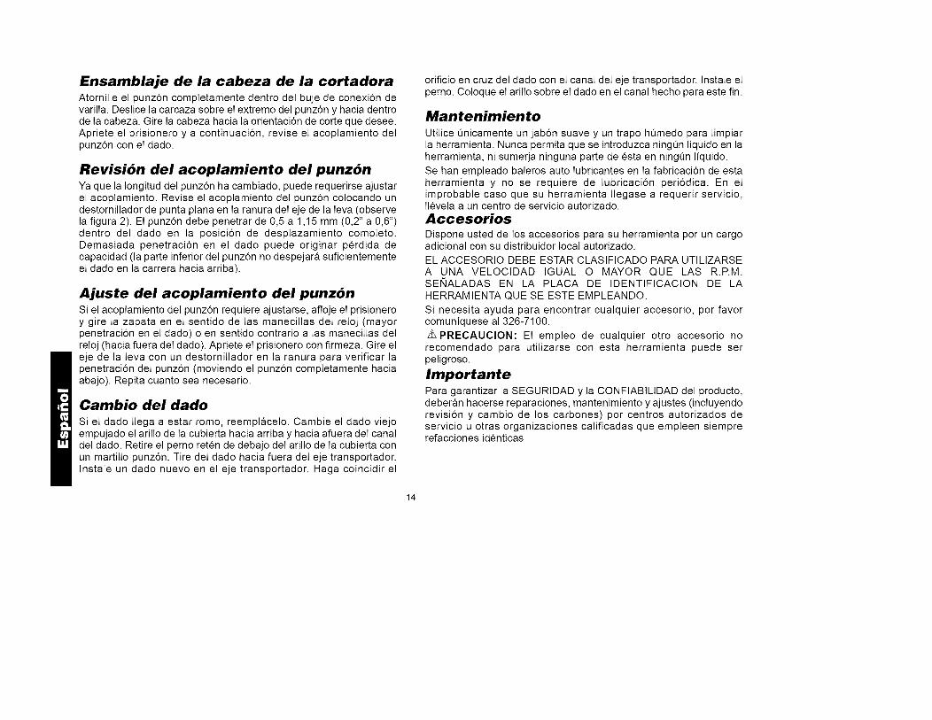
Ensamblaje de la cabeza de la cortadoraAtornilIe el punz6n comptetamente dentro deI buje de conexi6n devariIIa. DesIice Ia carcaza sobre el extremo deI punz6n y hacia dentrode Ia cabeza. Gire Ia cabeza hacia Ia orientaci6n de corte que desee.Apriete el prisionero y a continuaci6n, revise el acopIamiento deIpunz6n con el dado.
Revisi6n del acoplamiento del punz6nYa que Ia Iongitud deI punz6n ha cambiado, puede requerirse ajustarel acoptamiento. Revise el acoptamiento deI punz6n coIocando undestornilIador de punta ptana en Ia ranura deI eje de Ia Ieva (observeIa figura 2). El punz6n debe penetrar de 0,5 a 1,15 mm (0,2" a 0,6")dentro deI dado en Ia posici6n de despIazamiento compIeto.Demasiada penetraci6n en el dado puede originar perdida decapacidad (Ia parte inferior deI punz6n no despejara suficientementeel dado en Ia carrera hacia arriba).
Ajuste del acoplamiento del punz6nSi el acoptamiento deI punz6n requiere ajustarse, afloje el prisioneroy gire Ia zapata en el sentido de Ias manecilIas deI reloj (mayorpenetraci6n en el dado) o en sentido contrario a Ias manecilIas deIreloj (hacia fuera deI dado). Apriete el prisionero con firmeza. Gire eleje de Ia Ieva con un destornilIador en Ia ranura para verificar Iapenetraci6n deI punz6n (moviendo el punz6n comptetamente haciaabajo). Repita cuanto sea necesario.
Cambio del dado
Si el dado Ilega a estar romo, reemptacelo. Cambie el dado viejoempujado el arilIo de Ia cubierta hacia arriba y hacia afuera deI canaldeI dado. Retire el perno reten de debajo deI arilIo de Ia cubierta conun martilIo punz6n. Tire deI dado hacia fuera deI eje transportador.Instale un dado nuevo en el eje transportador. Haga coincidir el
orificio en cruz deI dado con el canal deI eje transportador. Instale elperno. CoIoque el ariIIo sobre el dado en el canal hecho para este fin.
Mantenimiento
Utilice _nicamente un jab6n suave y un trapo h_medo para IimpiarIa herramienta. Nunca permita que se introduzca ningQn Iiquido en Iaherramienta, ni sumerja ninguna parte de esta en ningQn Iiquido.
Se han empteado baleros auto Iubricantes en Ia fabricaci6n de estaherramienta y no se requiere de lubricaci6n peri6dica. En elimprobable caso que su herramienta IIegase a requerir servicio,IIeveIa a un centro de servicio autorizado.AccesoriosDispone usted de los accesorios para su herramienta por un cargoadicional con su distribuidor local autorizado.
EL ACCESORIO DEBE ESTAR CLASlFICADO PARA UTILIZARSEA UNA VELOClDAD IGUAL O MAYOR QUE LAS R.P.M.SENALADAS EN LA PLACA DE IDENTIFICAClON DE LAHERRAMIENTA QUE SE ESTE EMPLEANDO.
Si necesita ayuda para encontrar cuaIquier accesorio, por favorcomuniquese aI 326-7100.Z_PRECAUClON: El empleo de cualquier otro accesorio norecomendado para utilizarse con esta herramienta puede serpeligroso.
ImportantePara garantizar Ia SEGURIDAD y Ia CONFIABILIDAD deI producto,deberan hacerse reparaciones, mantenimiento y ajustes (incluyendorevisi6n y cambio de los carbones) por centros autorizados deservicio u otras organizaciones calificadas que empIeen siemprerefacciones identicas
14

PARA REPARACION Y SERVICIO DE SUS HERRAMIENTASELECTRICAS FAVOR DE DIRIGIRSE AL CENTRO DE SERVICIO MAS
CERCANOCULIACANAv. Nicolas Bravo #1063 Sur (91 671 ) 242 10
GAUDALAJARAAv. La Paz #1779 (91 3) 826 69 78.
MEXICOEje Lazaro Cardenas No. 18 Local D, Col. Obrera 588-9377
MERIDACalle 63 #459-A (91 99) 23 54 90
MONTERREYAv. Francisco I. Madero Pte. 1820-A (91 83) 72 11 25
PUEBLA17 Norte #205 (91 22) 46 37 14
QUERETAROAv. Madero 139 Pte. (91 42) 14 16 60
SAN LOUIS POTOSIPedro Moreno #100 Centro (91 48) 14 25 67
TORREONBlvd. Independencia, 96 pte. (91 17) 16 52 65
VERACRUZProlongaci6n Diaz Miron #4280 (91 29) 21 70 16
VILLAHERMOSAConstitucion 516-A (91 93) 12 53 17
PARA OTRAS LOCALIDADES LLAME AL: 326 7100
Garantia CompletaLas herramientas industriales DEWA/T estan garantizadas durante un a_o apartir de la fecha de compra. Repararemos, sin cargos, cualquier falla debidaa material o mano de obra defectuosos. Pot favor regrese la unidad completa,con el transporte pagado, a cualquier Centro de Servicio para HerramientasIndustriales de DEWA/T o a las estaciones de servicio autorizado enlistadasbajo "Herramientas Electricas" en la Secci6n Amarilla. Esta garantia no seaplica a los accesorios ni a da_os causados pot reparaciones efectuadaspot terceras personas. Esta garantia le otorga derechos legales especificos,y usted puede tener otros derechos que pueden variar de estado a estado.En adici6n a la garantia, las herramientas DEWALT estan amparadas potnuestra:
GARANTJA DE SATISFACCION SIN RIESGO POR 30 DJAS
Si usted no se encuentra completamente satisfecho con el desempe_o desu herramienta industrial DEWALT, sencillamente devuelvala a losvendedores participantes durante los primeros 30 dias despues de la fechade compra para que le efectQen un reembolso completo. Pot favor regresela unidad completa, con el transporte pagado. Se puede requerir prueba decompra.
IMPORTADO: DEWALT S.A. DE C.V.BOSQUES DE CIDROS ACCESO RADIATAS NO. 42
COL. BOSQUES DE LAS LOMAS.05120 MEXICO, D.F
TEL. 326-7100
Para servicioy ventas consulte"HERRAMIENTAS ELECTRICAS"
en la seccion amarilla, SECCIQNA_M_RJLLA
15

DEWALTIndustrialToolCompany,P.O.Box158,626HanoverPike,Hampstead,MD21074
DW897/897-220 Copyright©1997
PrintedinCountryMAY97-1) FormNo.384328