INSTRUCTION MANUAL - Huss Licht & Ton
16
INSTRUCTION MANUAL Congratulations on choosing a Claypaky product! We thank you for your custom. Please note that this product, as all the others in the rich Claypaky range, has been designed and made with total quality to ensure excellent performance and best meet your expectations and requirements. INDEX ENGLISH Page Contents 2 1. Safety information 3 2. Unpacking and preparation 4 3. Installation and start-up 4 3.1 Installing the fixture 4 3.2 Connecting to manis supply 5 3.3 Connecting the control signal line: DMX / Art-Net 5 3.4 Switching on the fixture and basic SetUp 7 4. Maintenance 7 4.1 Opening the covers 8 4.2 Periodical cleaning 9 4.3 Effects module removal 12 4.4 Cleaning of the filters 14 4.5 Rotating gobos 15 4.6 Battery removal 16 5. Specifications PRELIMINARY AXCOR PROFILE 400 AXCOR PROFILE 400 HC C61769 C61768
Transcript of INSTRUCTION MANUAL - Huss Licht & Ton
INSTRUCTION MANUAL
Congratulations on choosing a Claypaky product!We thank you for your custom.Please note that this product, as all the others in therich Claypaky range, has been designed and made withtotal quality to ensure excellent performance and bestmeet your expectations and requirements.
INDEX
ENGLISH
Page Contents
2 1. Safety information3 2. Unpacking and preparation4 3. Installation and start-up4 3.1 Installing the fixture4 3.2 Connecting to manis supply5 3.3 Connecting the control signal line: DMX / Art-Net5 3.4 Switching on the fixture and basic SetUp7 4. Maintenance7 4.1 Opening the covers8 4.2 Periodical cleaning9 4.3 Effects module removal12 4.4 Cleaning of the filters14 4.5 Rotating gobos15 4.6 Battery removal16 5. Specifications
PRELIMINARY
AXCOR PROFILE 400AXCOR PROFILE 400 HC
C61769
C61768
2AXCOR PROFILE 400 - 400 HC
EN
IT
DE
ES
FR
RU
SAFETY INFORMATIONIMPORTANT: Claypaky recommends you carefully read and keep the safety information on this product, alsoavailable in digital format at the following link:www.claypaky.comRef: FIS00T - Safety Information Axcor 400 series
INFORMAZIONI DI SICUREZZAIMPORTANTE: Claypaky raccomanda di leggere accuratamente e conservare le informazioni di sicurezza relativea questo prodotto, sempre reperibili in versione digitale al seguente link:www.claypaky.comRif: FIS00T - Safety Information Axcor 400 series
INFORMATIONEN ZUR SICHERHEITWICHTIG: Claypaky empfiehlt, die Sicherheitsinformationen bezüglich dieses Produkts genau zu lesen undaufzubewahren. Sie sind in Digitalversion immer unter folgendem Link auffindbar:www.claypaky.comRef: FIS00T - Safety Information Axcor 400 series
INFORMACIONES DE SEGURIDADIMPORTANTE: Claypaky recomienda leer detenidamente y conservar la información de seguridad relativa a esteproducto. Además, está disponible una versión digital de la misma en el siguiente enlace:www.claypaky.comRef: FIS00T - Safety Information Axcor 400 series
CONSIGNES DE SÉCURITÉIMPORTANT: Claypaky recommande de lire attentivement et de conserver les informations de sécurité relatives àce produit, disponibles en version digitale au lien suivant:www.claypaky.comRéf. : FIS00T - Safety Information Axcor 400 series
ИНСТРУКЦИЮ ПО ТЕХНИКЕ БЕЗОПАСНОСТИВАЖНО: Claypaky рекомендует внимательно прочитать и сохранить инструкцию по технике безопасностиданного изделия, которая всегда доступна в электронном формате по следующей ссылке:www.claypaky.comНаименование: FIS00T - Safety Information Axcor 400 series
1. SAFETY INFORMATION
3AXCOR PROFILE 400 - 400 HC
1
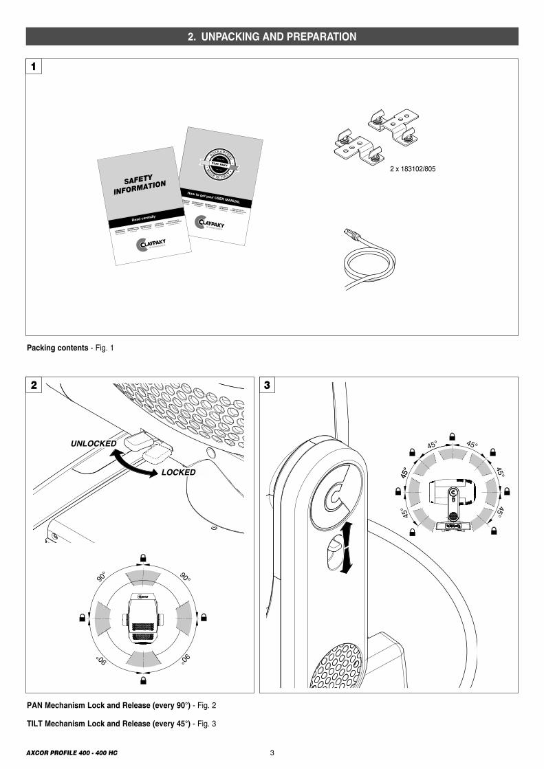
PAN Mechanism Lock and Release (every 90°) - Fig. 2
TILT Mechanism Lock and Release (every 45°) - Fig. 3
2 3
Packing contents - Fig. 1
90°
90°90°
90°
LOCKED
UNLOCKED
45°
45°
45°
45°
45°
45° 45°
2 x 183102/805
2. UNPACKING AND PREPARATION
4AXCOR PROFILE 400 - 400 HC
4
2
1
1
23
5
3. INSTALLATION AND START-UP
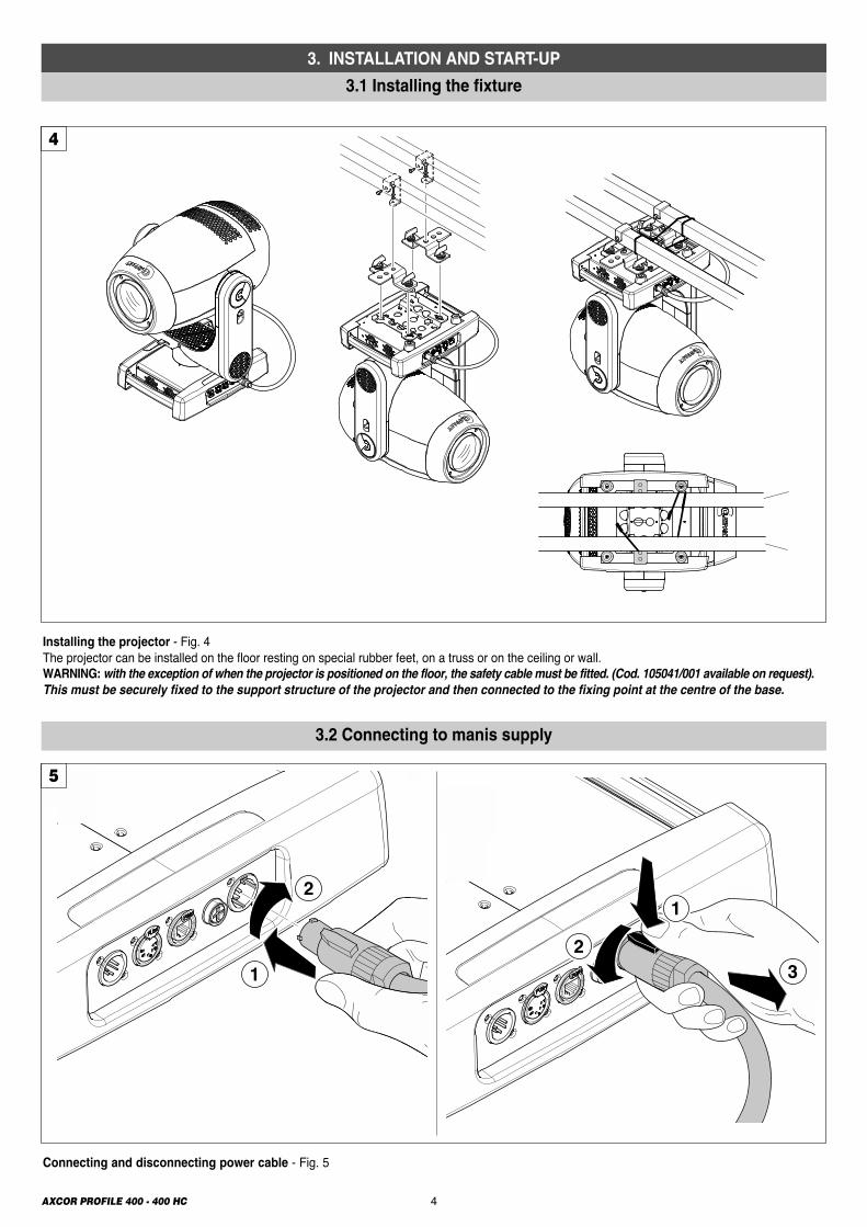
Connecting and disconnecting power cable - Fig. 5
Installing the projector - Fig. 4The projector can be installed on the floor resting on special rubber feet, on a truss or on the ceiling or wall. WARNING:with the exception of when the projector is positioned on the floor, the safety cable must be fitted. (Cod. 105041/001 available on request).This must be securely fixed to the support structure of the projector and then connected to the fixing point at the centre of the base.
3.1 Installing the fixture
3.2 Connecting to manis supply
5AXCOR PROFILE 400 - 400 HC
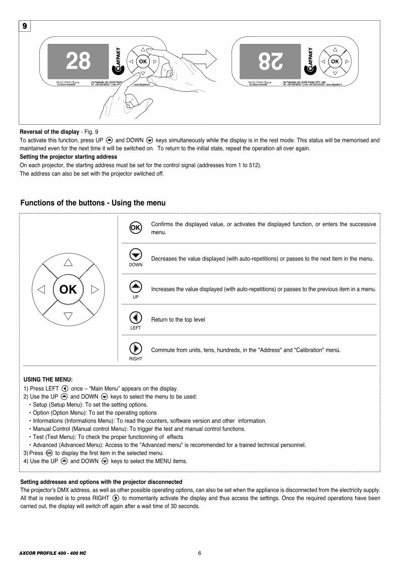
Switching on the projector - Fig. 8Press the switch. The projector starts resetting the effects. At the same time, the following information scrolls on the display:
Model Firmware Dmx Address xxx System errors Axcor Version X.X.X ......................... 400 Date - Hour .........................
On conclusion of resetting in case of absence of the dmx signal, Pan and Tilt move to the “Home” position (Pan 128 bit - Tilt 128 bit). The control panel(Fig. 8) has a display and buttons for the complete programming and management of the projector menu. The display can be in one of two conditions:rest status and setting status. When it is in the rest status, the display shows the projector’s DMX address. During menu setting status, after a wait time (about 30 seconds) without any key having been pressed, the display automatically returns to rest status.It should be noted than when this condition occurs, any possible value that has been modified but not yet confirmed with theF key will be cancelled.
1Dmx Address
Warning Message
8
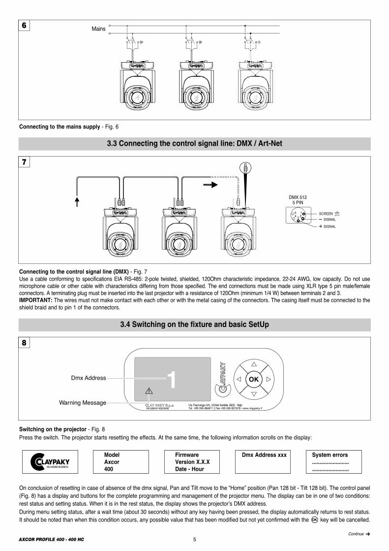
Connecting to the control signal line (DMX) - Fig. 7Use a cable conforming to specifications EIA RS-485: 2-pole twisted, shielded, 120Ohm characteristic impedance, 22-24 AWG, low capacity. Do not usemicrophone cable or other cable with characteristics differing from those specified. The end connections must be made using XLR type 5 pin male/femaleconnectors. A terminating plug must be inserted into the last projector with a resistance of 120Ohm (minimum 1/4 W) between terminals 2 and 3.IMPORTANT: The wires must not make contact with each other or with the metal casing of the connectors. The casing itself must be connected to theshield braid and to pin 1 of the connectors.
Connecting to the mains supply - Fig. 6
SIGNALSCREEN
DMX 5125 PIN
1234
5
SIGNAL
Mains6
7
Continue �
3.3 Connecting the control signal line: DMX / Art-Net
3.4 Switching on the fixture and basic SetUp
AXCOR PROFILE 400 - 400 HC 6
28 28
Reversal of the display - Fig. 9To activate this function, press UP B and DOWN C keys simultaneously while the display is in the rest mode. This status will be memorised andmaintained even for the next time it will be switched on. To return to the initial state, repeat the operation all over again.Setting the projector starting addressOn each projector, the starting address must be set for the control signal (addresses from 1 to 512). The address can also be set with the projector switched off.
9
Functions of the buttons - Using the menu
Setting addresses and options with the projector disconnectedThe projector’s DMX address, as well as other possible operating options, can also be set when the appliance is disconnected from the electricity supply.All that is needed is to press RIGHT E to momentarily activate the display and thus access the settings. Once the required operations have beencarried out, the display will switch off again after a wait time of 30 seconds.
USING THE MENU:
1) Press LEFT D once – “Main Menu” appears on the display.2) Use the UP B and DOWN C keys to select the menu to be used:• Setup (Setup Menu): To set the setting options.• Option (Option Menu): To set the operating options• Informations (Informations Menu): To read the counters, software version and other information.• Manual Control (Manual control Menu): To trigger the test and manual control functions.• Test (Test Menu): To check the proper functionning of effects• Advanced (Advanced Menu): Access to the "Advanced menu" is recommended for a trained technical personnel.
3) Press F to display the first item in the selected menu.4) Use the UP B and DOWN C keys to select the MENU items.
Confirms the displayed value, or activates the displayed function, or enters the successivemenu.
Decreases the value displayed (with auto-repetitions) or passes to the next item in the menu.
Increases the value displayed (with auto-repetitions) or passes to the previous item in a menu.
Return to the top level
Commute from units, tens, hundreds, in the "Address" and "Calibration" menù.
F
CDOWN
BUP
DLEFT
ERIGHT
7AXCOR PROFILE 400 - 400 HC
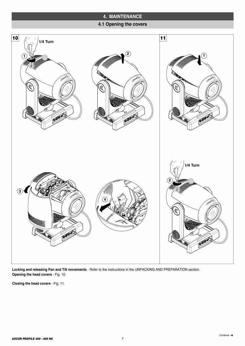
Locking and releasing Pan and Tilt movements - Refer to the instructions in the UNPACKING AND PREPARATION section.Opening the head covers - Fig. 10.
Closing the head covers - Fig. 11.
1/4 Turn
2
1/4 Turn
1 2 1
4
3
10 11
Continue �
4. MAINTENANCE
4.1 Opening the covers
Lower side
Upper side
8AXCOR PROFILE 400 - 400 HC
12
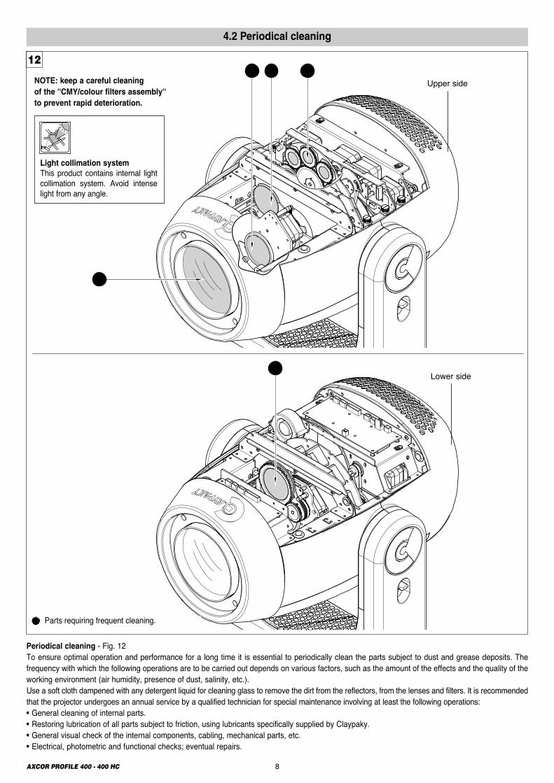
Periodical cleaning - Fig. 12To ensure optimal operation and performance for a long time it is essential to periodically clean the parts subject to dust and grease deposits. Thefrequency with which the following operations are to be carried out depends on various factors, such as the amount of the effects and the quality of theworking environment (air humidity, presence of dust, salinity, etc.). Use a soft cloth dampened with any detergent liquid for cleaning glass to remove the dirt from the reflectors, from the lenses and filters. It is recommendedthat the projector undergoes an annual service by a qualified technician for special maintenance involving at least the following operations:• General cleaning of internal parts.• Restoring lubrication of all parts subject to friction, using lubricants specifically supplied by Claypaky.• General visual check of the internal components, cabling, mechanical parts, etc.• Electrical, photometric and functional checks; eventual repairs.
NOTE: keep a careful cleaning of the ''CMY/colour filters assembly'' to prevent rapid deterioration.
Light collimation systemThis product contains internal lightcollimation system. Avoid intenselight from any angle.
4.2 Periodical cleaning
Parts requiring frequent cleaning.
9AXCOR PROFILE 400 - 400 HCContinue �
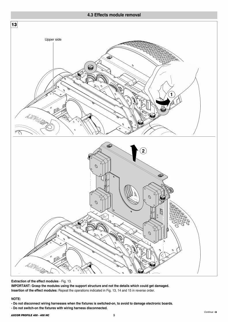
4.3 Effects module removal
1
2
Upper side
Extraction of the effect modules - Fig. 13.IMPORTANT: Grasp the modules using the support structure and not the details which could get damaged.Insertion of the effect modules: Repeat the operations indicated in Fig. 13, 14 and 15 in reverse order.
NOTE:- Do not disconnect wiring harnesses when the fixtures is switched-on, to avoid to damage electronic boards.- Do not switch-on the fixtures with wiring harness disconnected.
13
Upper side
2
1
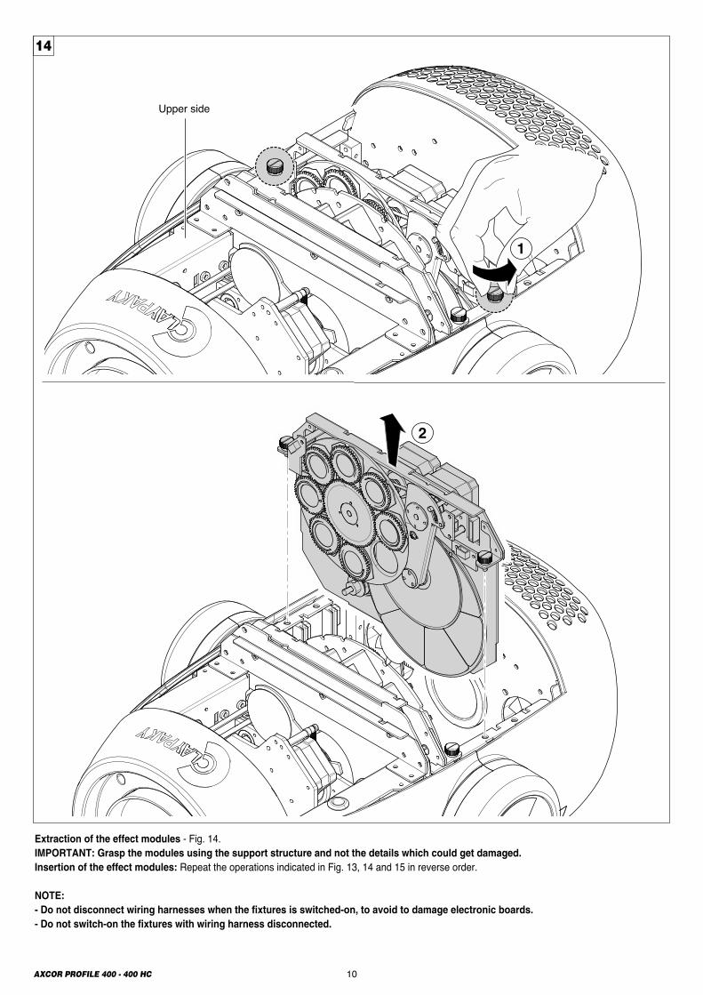
Extraction of the effect modules - Fig. 14.IMPORTANT: Grasp the modules using the support structure and not the details which could get damaged.Insertion of the effect modules: Repeat the operations indicated in Fig. 13, 14 and 15 in reverse order.
NOTE:- Do not disconnect wiring harnesses when the fixtures is switched-on, to avoid to damage electronic boards.- Do not switch-on the fixtures with wiring harness disconnected.
14
10AXCOR PROFILE 400 - 400 HC
11AXCOR PROFILE 400 - 400 HC
Upper side
1
2
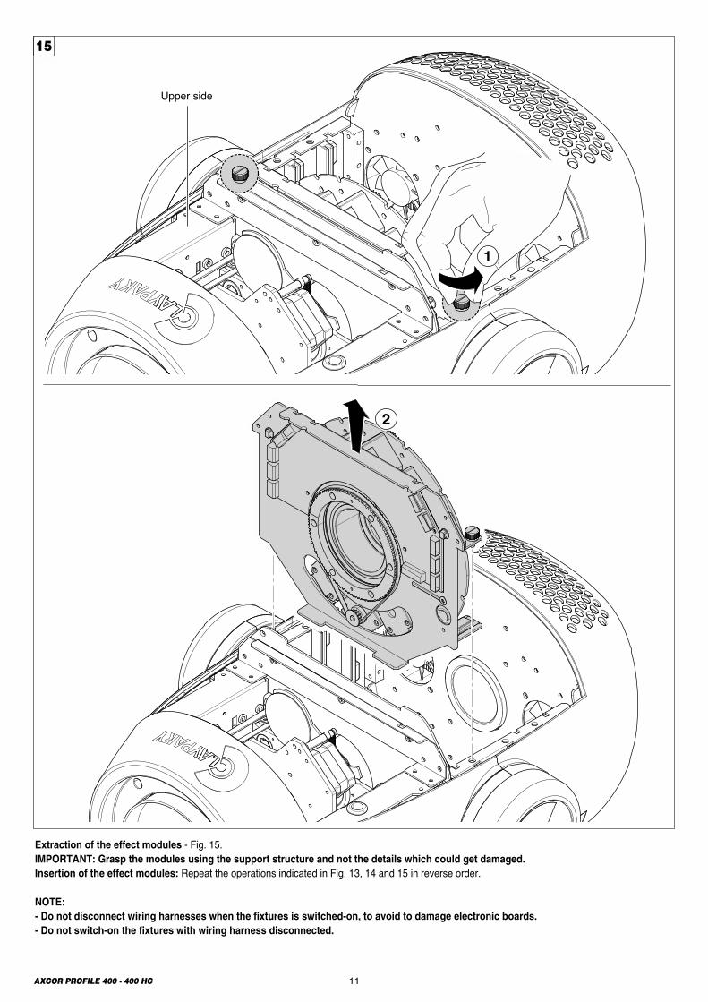
Extraction of the effect modules - Fig. 15.IMPORTANT: Grasp the modules using the support structure and not the details which could get damaged.Insertion of the effect modules: Repeat the operations indicated in Fig. 13, 14 and 15 in reverse order.
NOTE:- Do not disconnect wiring harnesses when the fixtures is switched-on, to avoid to damage electronic boards.- Do not switch-on the fixtures with wiring harness disconnected.
15
12AXCOR PROFILE 400 - 400 HC
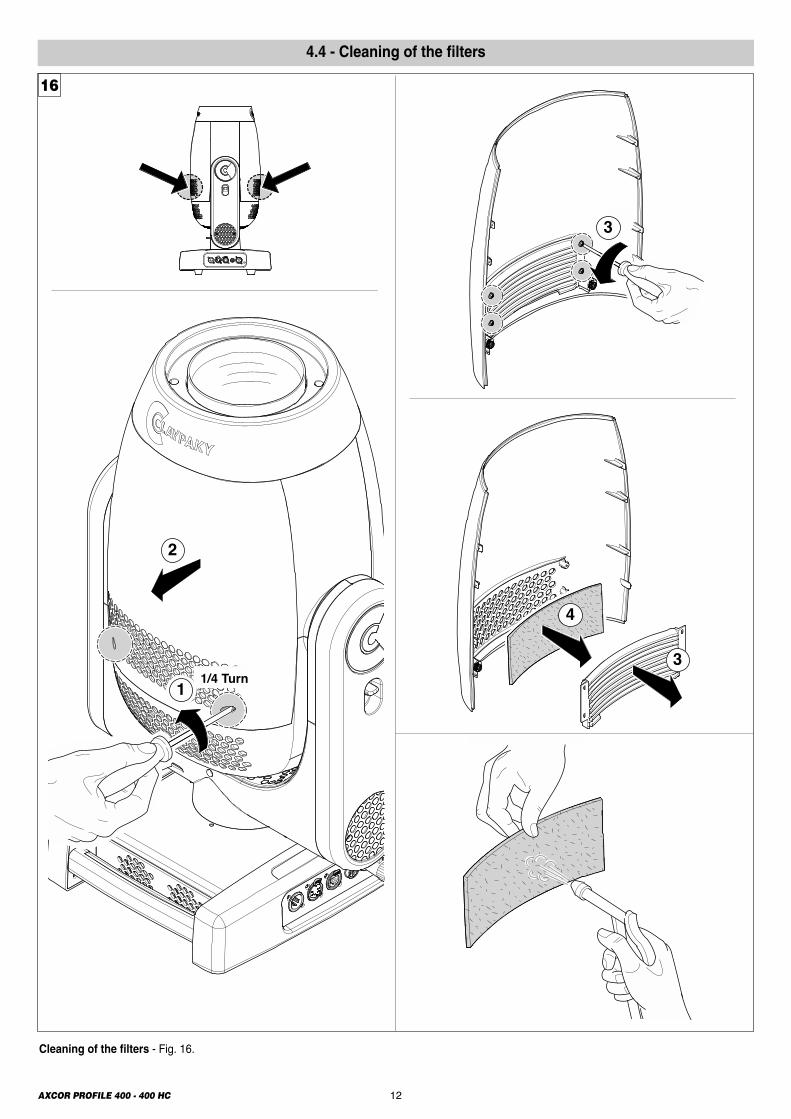
Cleaning of the filters - Fig. 16.
2
1 1/4 Turn3
4
3
16
4.4 - Cleaning of the filters
13AXCOR PROFILE 400 - 400 HC
1
1/4 Turn
2
5
4
5
4
3
5
4
17
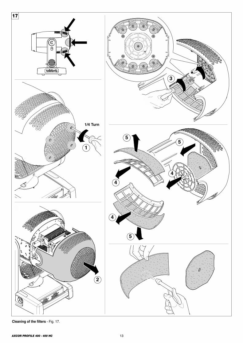
Cleaning of the filters - Fig. 17.
14AXCOR PROFILE 400 - 400 HC
1
3
2
1 ±0.1
ø22.
9Im
mag
ine ø
17.5
INDEX
4th 6th
2nd
1st
3rd
5th
7th
19
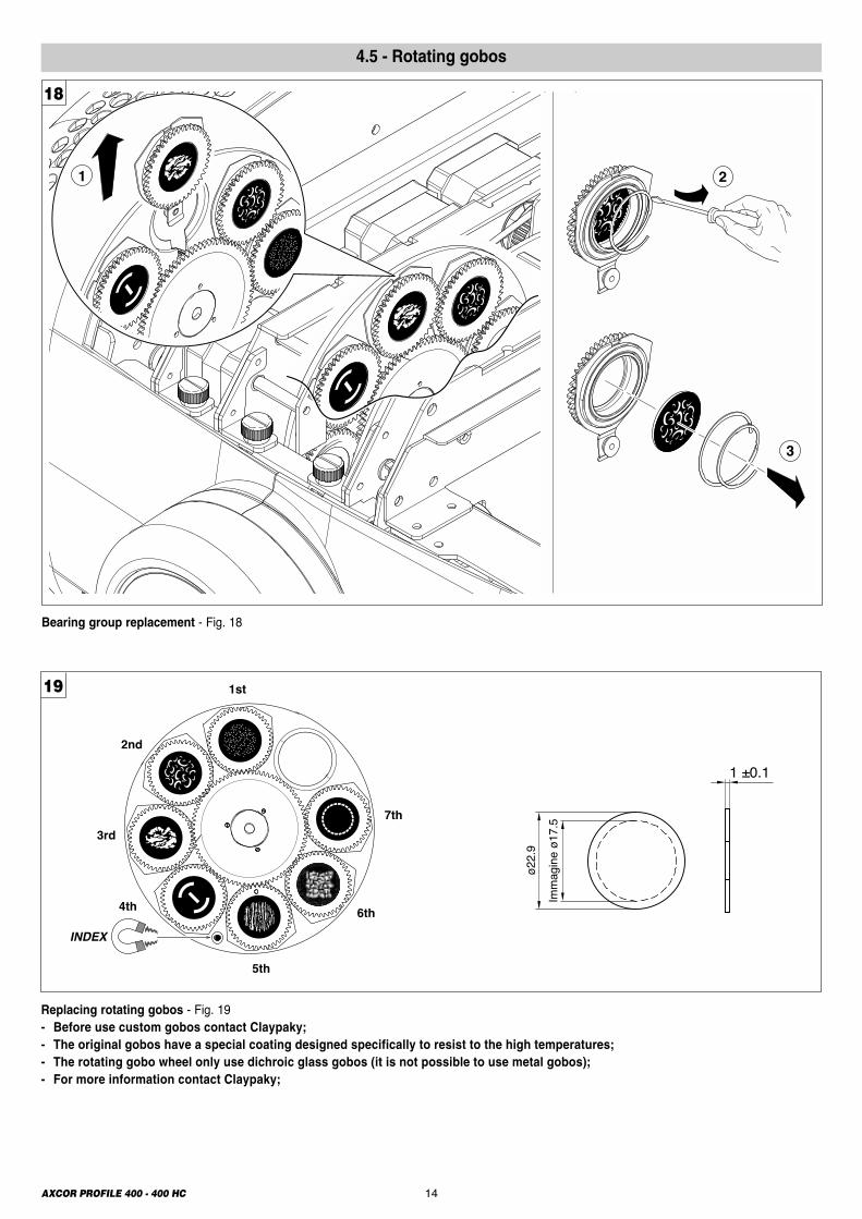
Replacing rotating gobos - Fig. 19- Before use custom gobos contact Claypaky; - The original gobos have a special coating designed specifically to resist to the high temperatures; - The rotating gobo wheel only use dichroic glass gobos (it is not possible to use metal gobos); - For more information contact Claypaky;
Bearing group replacement - Fig. 18
18
4.5 - Rotating gobos
15AXCOR PROFILE 400 - 400 HC
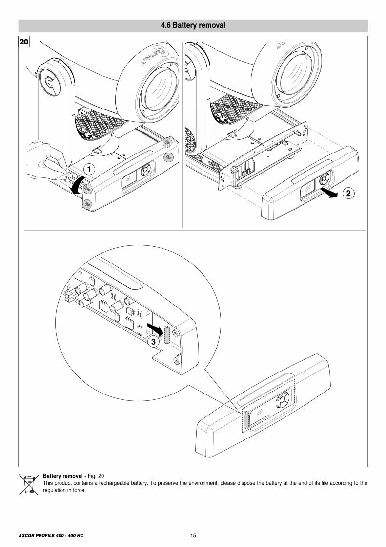
Battery removal - Fig. 20This product contains a rechargeable battery. To preserve the environment, please dispose the battery at the end of its life according to theregulation in force.
4.6 Battery removal
1
2
3
20
647(25.47")
276(10.83")
350(13.78")
376(14.80")
470(18.50")
490(19.29")
531(20.90")
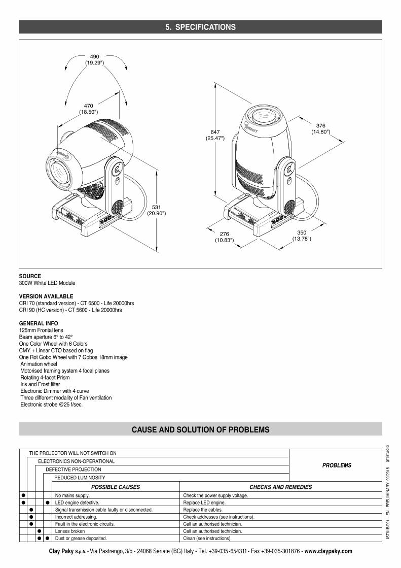
SOURCE300W White LED Module
VERSION AVAILABLECRI 70 (standard version) - CT 6500 - Life 20000hrs CRI 90 (HC version) - CT 5600 - Life 20000hrs
GENERAL INFO125mm Frontal lens Beam aperture 6° to 42° One Color Wheel with 6 Colors CMY + Linear CTO based on flag One Rot Gobo Wheel with 7 Gobos 18mm image Animation wheel Motorised framing system 4 focal planes Rotating 4-facet Prism Iris and Frost filter Electronic Dimmer with 4 curve Three different modality of Fan ventilation Electronic strobe @25 f/sec.
5. SPECIFICATIONS
Clay Paky S.p.A. - Via Pastrengo, 3/b - 24068 Seriate (BG) Italy - Tel. +39-035-654311 - Fax +39-035-301876 - www.claypaky.com
IST01B/00
1 – EN - PRE
LIMINAR
Y 09
/2018
CAUSE AND SOLUTION OF PROBLEMS
THE PROJECTOR WILL NOT SWITCH ON
PROBLEMSELECTRONICS NON-OPERATIONALDEFECTIVE PROJECTION
REDUCED LUMINOSITYPOSSIBLE CAUSES CHECKS AND REMEDIES
No mains supply.LED engine defective.Signal transmission cable faulty or disconnected.Incorrect addressing.Fault in the electronic circuits.Lenses brokenDust or grease deposited.
Check the power supply voltage.Replace LED engine.Replace the cables.Check addresses (see instructions).Call an authorised technician.Call an authorised technician.Clean (see instructions).