Parts & Service Manual - huss-licht-ton.de · Parts & Service Manual Part No. 80140 ... C-4 Inspect...
88
Parts & Service Manual Part No. 80140 Rev B3 April 2006 Refer to inside cover for additional serial number information
Transcript of Parts & Service Manual - huss-licht-ton.de · Parts & Service Manual Part No. 80140 ... C-4 Inspect...

Parts & Service Manual Part No. 80140
Rev B3
April 2006Refer to inside cover for additional serial number information

Genie Superlift Contractor Part No. 80140
August 2004Introduction
ii
Important
Read, understand and obey the safety rules andoperating instructions in the appropriate Operator'sManual on your machine before attempting anymaintenance procedure.
Basic mechanical, hydraulic and electricalskills are required to perform most procedures.However, several procedures require specializedskills, tools, lifting equipment and a suitableworkshop. In these instances, we stronglyrecommend that maintenance and repair beperformed at an authorized Genie dealerservice center.
Technical Publications
Genie Industries has endeavored to deliver thehighest degree of accuracy possible. However,continuous improvement of our products is a Geniepolicy. Therefore, product specificationsare subject to change without notice.
Readers are encouraged to notify Genie of errorsand send in suggestions for improvement. Allcommunications will be carefully considered forfuture printings of this and all other manuals.
Contact Us:
www.genieindustries.come-mail: [email protected]
Serial Number Information
Genie Industries offers the following ServiceManuals for these models:
Title Part No.
Genie Superlift Contractor Parts and Service Manual,First Edition(before serial number 9595-101) .......................... 33953
Copyright © 1995 by Genie Industries
80140 Rev B August 2004Second Edition, Second Printing
"Genie" is a registered trademark of GenieIndustries in the USA and many other countries."SLC" is a trademark of Genie Industries.
Printed on recycled paper
Printed in U.S.A.

Part No. 80140 Genie Superlift Contractor
August 2004
iii
Safety Rules
WarningFailure to obey the instructions and safety rules inthis manual and the Genie Superlift ContractorOperator's Manual could result in death or seriousinjury.
Many of the hazards identified in the operatinginstruction manual are also safety hazards whenmaintenance and repair procedures are performed.
Do Not Perform MaintenanceUnless:
You are trained and qualified to performmaintenance on this machine.
You read, understand and obey:- manufacturer’s instructions and safety rules- employer’s safety rules and worksite
regulations- applicable governmental regulations
You have the appropriate tools, liftingequipment and a suitable workshop.

Genie Superlift Contractor Part No. 80140
August 2004
iv
Personal SafetyAny person working on or around a machine mustbe aware of all known safety hazards. Personalsafety and the continued safe operation of themachine should be your top priority.
Read each procedure thoroughly. Thismanual and the decals on the machine,use signal words to identify the following:
Safety alert symbol—used to alertpersonnel to potential personalinjury hazards. Obey all safetymessages that follow this symbolto avoid possible injury or death.
Red—used to indicate thepresence of an imminentlyhazardous situation which, if notavoided, will result in death orserious injury.
Orange—used to indicate thepresence of a potentiallyhazardous situation which, if notavoided, could result in death orserious injury.
Yellow with safety alert symbol—used to indicate the presence of apotentially hazardous situationwhich, if not avoided, may causeminor or moderate injury.
Yellow without safety alertsymbol—used to indicate thepresense of a potentiallyhazardous situation which, if notavoided, may result in propertydamage.
Green—used to indicate operationor maintenance information.
Be sure to wear protective eye wear andother protective clothing if the situationwarrants it.
Be aware of potential crushing hazardssuch as moving parts, free swinging orunsecured components when lifting or
placing loads. Always wear approved steel-toedshoes.
Workplace SafetyBe sure to keep sparks, flames andlighted tobacco away from flammableand combustible materials like battery
gases and engine fuels. Always have an approvedfire extinguisher within easy reach.
Be sure that all tools and working areasare properly maintained and ready foruse. Keep work surfaces clean and free
of debris that could get into machine componentsand cause damage.
Be sure that your workshop or work areais properly ventilated and well lit.
Be sure any forklift, overhead crane orother lifting or supporting device is fullycapable of supporting and stabilizing the
weight to be lifted. Use only chains or straps thatare in good condition and of ample capacity.
Be sure that fasteners intended for onetime use (i.e., cotter pins and self-lockingnuts) are not reused. These components
may fail if they are used a second time.
Be sure to properly dispose of old oil orother fluids. Use an approved container.
Please be environmentally safe .
SAFETY RULES

Part No. 80140 Genie Superlift Contractor
August 2004
v
Table of Contents
Introduction
Important Information ......................................................................................... ii
Recommended Parts Stocking List ................................................................... ix
How To Order Parts .......................................................................................... x
Service Parts Fax Order Form .......................................................................... xi
Section 1 Safety Rules
General Safety Rules ........................................................................................ iii
Section 2 Rev Specifications
A SLC-6 .......................................................................................................... 2 - 1
A SLC-12 ........................................................................................................ 2 - 1
A SLC-18 ........................................................................................................ 2 - 1
A SLC-24 ........................................................................................................ 2 - 1
Section 3 Rev Scheduled Maintenance Procedures
Introduction .................................................................................................. 3 - 1
Pre-delivery Preparation Report ................................................................... 3 - 3
Maintenance Inspection Report ................................................................... 3 - 4
A Checklist A Procedures
A-1 Perform Pre-operation Inspection ....................................................... 3 - 5
A-2 Perform Function Tests ...................................................................... 3 - 5
A Checklist B Procedures
B-1 Inspect all Welds ................................................................................ 3 - 6
B-2 Clean the Columns ............................................................................. 3 - 6
B-3 Inspect and Lubricate the Winch ........................................................ 3 - 7
B-4 Inspect the Carriage Hold-Down Bar .................................................. 3 - 8
A Checklist C Procedures
C-1 Lubricate the Casters and Wheels ...................................................... 3 - 9
C-2 Inspect the Mast Assembly for Wear .................................................. 3 - 9
C-3 Replace the Winch Friction Discs ..................................................... 3 - 10
C-4 Inspect the Safety Brake System (if equipped) ................................. 3 - 11
C-5 Inspect the Painted Surfaces ............................................................ 3 - 12

Genie Superlift Contractor Part No. 80140
April 2006
TABLE OF CONTENTS
Section 4 Rev Troubleshooting Flow Charts
Introduction .................................................................................................. 4 - 1
A Chart 1: Mast Will Not Sequence Properly ................................................... 4 - 2
A Chart 2: Carriage Will Not Raise, But Winch Will Operate ........................... 4 - 3
A Chart 3: Winch Will Not Operate .................................................................. 4 - 4
Section 5 Rev Repair Procedures
Introduction .................................................................................................. 5 - 1
A 1-1 Base Assembly ................................................................................ 5 - 2
A 2-1 Mast Assembly ................................................................................ 5 - 3
A 2-2 Lifting Cable ..................................................................................... 5 - 7
A 2-3 Lifting Pulley .................................................................................... 5 - 8
A 3-1 One-Speed Winch .......................................................................... 5 - 10
A 3-2 Two-Speed Winch .......................................................................... 5 - 13
Section 6 Rev Decals and Paint
Figure 6-A A Decals with Words (before serial number SLC04-28241) ............................ 6 - 2
Figure 6-B A Decals with Words (after serial number SLC04-28240) ............................... 6 - 4
Figure 6-C A Decals with Symbols .................................................................................... 6 - 6
Section 7 Rev Base Components
Figure 7-A A Base Components, View 1 ........................................................................... 7 - 2
Figure 7-B B Base Components, View 2 ........................................................................... 7 - 4
Section 8 Rev Mast and Winch Components
Figure 8-A B Mast Components, View 1 ........................................................................... 8 - 2
Figure 8-B A Mast Components, View 2 ........................................................................... 8 - 4
Figure 8-C B Mast Components, View 3 ........................................................................... 8 - 6
Figure 8-D B Columns, Pulleys and Cables .................................................................... 8 - 10
Figure 8-E A Winch Components, Single Speed ............................................................ 8 - 12
Figure 8-F A Winch Components, Two Speed (after serial number 9501-16465) ........... 8 - 14
vi

Part No. 80140 Genie Superlift Contractor
April 2006
TABLE OF CONTENTS
vii
Section 9 Rev Accesories
Figure 9-A A Forks ........................................................................................................... 9 - 2
Figure 9-B A Pipe Cradle. Load Platform and Boom Arm ................................................. 9 - 4
Figure 9-C A Rear Wheels ................................................................................................ 9 - 6
Genie Superlift Contractor Part No. 80140
August 2004
Notes
viii

Part No. 80140 Genie Superlift Contractor
August 2004
ix
Parts Stocking List
Required Parts
The following parts are required to performmaintenance procedures as outlined in the GenieSuperlift Contractor Parts and Service Manual.
Description Part No.
White Lithium Grease .......................................... 91670
Cable Replacement Coupler ................................ 12402
Disc Brake (One Speed Winch) ............................. 7571
Disc Brake (Two Speed Winch) ........................... 80157
Recommended PartsDescription Part No.
Genie Gray Paint, 12 Ounce (355 ml) Aerosol ...... 1268
Genie Blue Paint, 12 Ounce (355 ml) Aerosol ....... 1484
Genie Blue Paint, 1 Gallon (3.78 liters) ............... 32150
Genie Gray Paint, 1 Gallon (3.78 liters) ............... 32151
Pinion Plate (One Speed Winch) ........................... 7591
Pinion Plate (Two Speed Winch) ......................... 40122
Ratchet Gear (One Speed Winch) ......................... 6777
Ratchet Gear (Two Speed Winch) ....................... 40121
Pinion Gear (One Speed Winch) ........................... 7590
Pinion Gear (Two Speed Winch) ......................... 80157
Pinion Shaft (One Speed Winch) ......................... 32891
Ratchet Pawl Kit (One Speed Winch) .................. 40458
Ratchet Pawl Kit (Two Speed Winch) .................. 40117
Cable Keeper Kit (One Speed Winch) ................... 6190
Primary Shaft Assembly....................................... 72264
Cable Assembly (SLC-6 models) ......................... 35143
Cable Assembly (SLC-12 models) ....................... 35144
Cable Assembly (SLC-18 models) ....................... 35145
Cable Assembly (SLC-24 models) ....................... 35146
Pin Assembly with Lanyard .................................. 32940
Roller Bolt, 1/2-13 x 1.84 inches ........................... 32475
Nylatron Roller, 1.75 x 0.72 inch ......................... 32473
Safety Brake Assembly ........................................ 35101
Genie Superlift Cabling Procedure Video ............ 52701
Loctite Thread Lock ............................................. 65764
Manuals
Genie Industries offers the following supportdocuments for these models:
Title Part No.
Genie Superlift ContractorOperator's Manual, Second Edition ..................... 33547
Genie Superlift Parts and Service Manual,First Edition .......................................................... 33953
EMI Safety Manual ............................................... 27581

Genie Superlift Contractor Part No. 80140
August 2004
x
How To Order Parts
Please be prepared with the following informationwhen ordering replacement parts for your Genieproduct:
Machine model numberMachine serial numberGenie part numberPart description and quantityPurchase order number"Ship to" addressDesired method of shipmentName and telephone number of the authorizedGenie Distributor in your area
Use the Service Parts Fax Order Form on the nextpage and fax your order to our Parts Department.
If you don't know the name of your authorizeddistributor, or if your area is not currently servicedby an authorized distributor, please call GenieIndustries.
Machine Information
Model
Serial Number
Date of Purchase
Authorized Genie Distributor
Phone Number
Genie North AmericaTelephone (425) 556-6551Toll Free (877) 367-5606 in U.S.A. and CanadaFax (425) 556-8659
Genie UKParts Telephone (44) (0) 1476 584352Parts Fax (44) (0) 1476 584340
Genie AustraliaParts Telephone (617) 03375 1660Parts Fax (617) 03375 1002
Genie FranceParts Telephone (33) (0) 237 26 09 99Parts Fax (33) (0) 237 31 50 10
Genie GermanyParts Telephone (49) (0) 4202 885223Parts Fax (49) (0) 4202 885225
Genie ScandinaviaParts Telephone (46) (31) 3409612Parts Fax (46) (31) 3409613
Genie IbericaParts Telephone (34) (93) 5795042
Genie BrazilParts Telephone (55) (114) 1665755Parts Fax (55) (114) 1665754
Genie JapanParts Telephone (81) (33) 4536082Parts Fax (81) (33) 4536083
Genie ChinaParts Telephone (86) (215) 3852570Parts Fax (86) (215) 3852569

rem
ove
this
pag
e an
d m
ake
copi
es
Part Number Description Quantity Price
All back-ordered parts will be shipped when available via the same ship method as the original orderunless Noted below:
Ship complete order only - No back orders
Ship all available parts and contact customer on disposition of back-ordered parts
Other (please specify)
Please fill out completely
Date _________________________________ Account Number _______________________________
Your Name _______________________________ Your Fax Number ______________________________
_________________________________ Your Phone Number ____________________________
Bill To _________________________________ Ship To ___________________________________
_________________________________ ___________________________________
_________________________________ ___________________________________
_________________________________ ___________________________________
Purchase Order Number ____________________ Ship Via ___________________________________
Model(s) ______________________________________________________ Serial No.(s) _________________
Optional Equipment __________________________________________________________________________
FOR GENIE INDUSTRIES USE ONLY
Order Number ______________ Origin Code ________________ Comments _________________________
Date Scheduled ____________ Ship Condition ______________ __________________________________
Order Total ________________ Terms Code ________________ __________________________________
Service Parts Fax Order FormFax to: (425) 556-8659 or Toll Free: 888-274-6192
International: +1-425-556-8659
rem
ove
this
pag
e an
d m
ake
copi
es

Genie Superlift Contractor Part No. 80140
August 2004
This page intentionally left blank.

Section 2 • SpecificationsAugust 2004
Part No. 80140 Genie Superlift Contractor 2 - 1
Specifications
Model SLC-6 SLC-12 SLC-18 SLC-24
Height-Stowed 86 in 86 in 86 in 86 in2.2 m 2.2 m 2.2 m 2.2 m
Width 311/2 in 311/2 in 311/2 in 311/2 in80 cm 80 cm 80 cm 80 cm
Width - stabilizers lowered (if equipped) 66 in 66 in 66 in 66 in1.7 m 1.7 m 1.7 m 1.7 m
Length - Stowed 34 in 34 in 34 in 34 in86.4 cm 86.4 cm 86.4 cm 86.4 cm
Length - Operating 59 in 63 in 73 in 81 in1.5 m 1.6 m 1.9 m 2 m
Ground 2 in 2 in 2 in 2 inClearance 50.8 mm 50.8 mm 50.8 mm 50.8 mm
Load Capacity 650 lbs 650 lbs 650 lbs 650 lbsat 14in/36cm load center 295 kg 295 kg 295 kg 295 kgNote: see Load Capacity Charts section for load capacities at other load centers.
Net Weight 166 lbs 204 lbs 307 lbs 374 lbs75 kg 93 kg 139 kg 170 kg
Airborne Noise Emissions by Machinery 85 dB 85 dB 85 dB 85 dBMaximum sound level at normal operating work stations (A-weighted)
Load Handling Attachments Length Width Depth Net Weight
Standard Forks 28 in 23 in 21/2 in 261/2 lbs71.1 cm 58.4 cm 6.4 cm 12 kg
Adjustable Forks 271/2 in 111/2 to 30 in 21/2 in 521/2 lbs69.9 cm 29.2 to 76.2 cm 6.4 cm 23.8 kg
Boom 44 in 11/2 in 6 in 341/2 lbs1.1 m 3.8 cm 15.2 cm 15.6 kg
Pipe Cradle 271/2 in 241/2 in 6 in 10 lbs69.9 cm 62.2 cm 15.2 cm 4.5 kg
Load Platform 271/2 in 23 in 21/2 in 26 lbs69.9 cm 58.4 cm 6.4 cm 11.8 kg
Fork Extensions (each) 30 in 2 in 3 in 41/2 lbs76.2 cm 5.1 cm 7.6 cm 2 kg

August 2004
2 - 2 Genie Superlift Contractor Part No. 80140
Section 2 • Specifications
SPECIFICATIONS
Dimensions - Operating SLC-6 SLC-12 SLC-18 SLC-24
Standard Forks forks down 5 ft 8 in 11 ft 2 in 16 ft 9 in 22 ft 3 in1.7 m 3.4 m 5.1 m 6.8 m
forks up 7 ft 5 in 12 ft 11 in 18 ft 6 in 24 ft 0 in2.3 m 3.9 m 5.6 m 7.3 m
Adjustable Forks forks down 5 ft 8 in 11 ft 2 in 16 ft 9 in 22 ft 3 in1.7 m 3.4 m 5.1 m 6.8 m
forks up 7 ft 5 in 12 ft 11 in 18 ft 6 in 24 ft 0 in2.3 m 3.9 m 5.6 m 7.3 m
Boom 6 ft 8 in 12 ft 2 in 17 ft 9 in 23 ft 3 in2 m 3.7 m 5.4 m 7.1 m
Note: measured from ground to bottom of shackle
Load Platform forks down 5 ft 8 in 11 ft 2 in 16 ft 9 in 19 ft 6 in 22 ft 3 in1.7 m 3.4 m 5.1 m 6 m 6.8 m
forks up 7 ft 5 in 12 ft 11 in 18 ft 6 in 21 ft 21/2 in 24 ft 0 in2.3 m 3.9 m 5.6 m 6.5 m 7.3 m
Note: can be used with standard forks and adjustable forks only
Pipe Cradle: handles round objects up to 30 in (76 cm) in diameterNote: can be used with standard forks and adjustable forks only (see above for working heights)
Non-marking Fork OptionNote: can be used with standard forks and adjustable forks only (see above for working heights)
Fork Extension OptionNote: can be used with standard forks and adjustable forks only (see above for working heights)

August 2004 Section 3 • Scheduled Maintenance Procedures
Part No. 80140 Genie Superlift Contractor 3- 1
Observe and Obey:
Maintenance procedures shall be completed bya person trained and qualified on themaintenance of this machine.
Scheduled maintenance procedures shall becompleted daily, quarterly (every 3 months) andannually as specified on the maintenanceinspection report.
Failure to properly complete eachinspection when required couldresult in death, serious injury orsubstantial machine damage.
Immediately tag and remove from service adamaged or malfunctioning machine.
Repair any machine damage or malfunctionbefore operating machine.
Keep records on all inspections for three years.
Be sure the capacities of sawhorses or othersupports are sufficient to withstand machineweight. See Specification section for themachine weight.
Be sure overhead cranes or other lifting devicesare of ample capacity to handle machineweight. See Specification section for machineweight.
Unless otherwise specified, perform eachprocedure with the machine in the followingconfiguration:
· Machine positioned on a flat level surface
· Carriage fully lowered
· Casters locked
· Load handling attachment installed
Scheduled Maintenance Procedures
About This Section
This section contains detailed procedures for eachscheduled maintenance inspection.
Each procedure includes a description, safetywarnings and step-by-step instructions.
Symbols Legend
Safety alert symbol—used to alertpersonnel to potential personalinjury hazards. Obey all safetymessages that follow this symbolto avoid possible injury or death.
Red—used to indicate thepresence of an imminentlyhazardous situation which, if notavoided, will result in death orserious injury.
Orange—used to indicate thepresence of a potentiallyhazardous situation which, if notavoided, could result in death orserious injury.
Yellow with safety alert symbol—used to indicate the presence of apotentially hazardous situationwhich, if not avoided, may causeminor or moderate injury.
Yellow without safety alertsymbol—used to indicate thepresence of a potentiallyhazardous situation which, if notavoided, may result in propertydamage.
Green—used to indicate operationor maintenance information.
Indicates that a specific result is expected afterperforming a series of steps.

August 2004
3- 2 Genie Superlift Contractor Part No. 80140
Section 3 • Scheduled Maintenance Procedures
SCHEDULED MAINTENANCE PROCEDURES
Maintenance Symbols Legend
The following symbols have beenused in this manual to helpcommunicate the intent of theinstructions. When one or more ofthe symbols appears at thebeginning of a maintenanceprocedure, it conveys the meaningbelow.
Indicates that tools will be required toperform this procedure.
Indicates that new parts will berequired to perform this procedure.
Indicates that a cold motor or pumpwill be required to perform thisprocedure.
Indicates that dealer service will berequired to perform this procedure.
Pre-delivery Preparation Report
The pre-delivery preparation report containschecklists for each type of scheduled inspection.
Make copies of the Pre-delivery Preparation reportto use for each inspection. Store completed formsas required.
Maintenance Schedule
There are five types of maintenance inspectionsthat must be performed according to a schedule—daily, quarterly, semi-annually, annually, andtwo year. The Scheduled Maintenance ProceduresSection and the Maintenance Inspection Reporthave been divided into five subsections—A, B, C,D, and E. Use the following chart to determinewhich group(s) of procedures are required toperform a scheduled inspection.
Inspection Checklist
Daily or every 8 hours A
Quarterly or every 250 hours A + B
Semi-annually or every 500 hours A + B + C
Annually or every 1000 hours A + B + C + D
Two year or every 2000 hours A + B + C + D + E
Maintenance Inspection Report
The maintenance inspection report containschecklists for each type of scheduled inspection.
Make copies of the Maintenance Inspection Reportto use for each inspection. Store completed formsfor three years.

August 2004 Section 3 • Scheduled Maintenance Procedures
Part No. 80140 Genie Superlift Contractor 3- 3
Pre-DeliverPre-DeliverPre-DeliverPre-DeliverPre-Delivery Preparationy Preparationy Preparationy Preparationy Preparation
Fundamentals
It is the responsibility of the dealer to perform thePre-delivery Preparation.
The Pre-delivery Preparation is performed prior toeach delivery. The inspection is designed to discover ifanything is apparently wrong with a machine before itis put into service.
A damaged or modified machine must never be used.If damage or any variation from factory deliveredcondition is discovered, the machine must be taggedand removed from service.
Repairs to the machine may only be made by aqualified service technician, according to themanufacturer's specifications.
Scheduled maintenance inspections shall beperformed by qualified service technicians, accordingto the manufacturer's specifications and therequirements listed in the responsibilities manual.
Instructions
Use the operator’s manual on your machine.
The Pre-delivery Preparation consists of completingthe Pre-operation Inspection, the Maintenance itemsand the Function Tests.
Use this form to record the results. Place a check inthe appropriate box after each part is completed.Follow the instructions in the operator’s manual.
If any inspection receives an N, remove the machinefrom service, repair and re-inspect it. After repair,place a check in the R box.
LegendY = yes, completedN = no, unable to completeR = repaired
Comments
Pre-Delivery Preparation Y N R
Pre-operation inspectioncompleted
Maintenance items completed
Function tests completed
Model
Serial number
Date
Machine owner
Inspected by (print)
Inspector signature
Inspector title
Inspector company
Copyright © 2002 by Genie Industries. Genie® is a registered trademark of GenieIndustries. Rev A
Genie Industries USA18340 NE 76th StreetPO Box 97030Redmond, WA 98073-9730(425) 881-1800
Genie UKThe Maltings, Wharf Road
Grantham, LincolnshireNG31- 6BH England
(44) 1476-584333

August 2004
3- 4 Genie Superlift Contractor Part No. 80140
Section 3 • Scheduled Maintenance Procedures
This page intentionally left blank.
August 2004 Section 3 • Scheduled Maintenance Procedures
Part No. 80140 Genie Superlift Contractor 3- 5
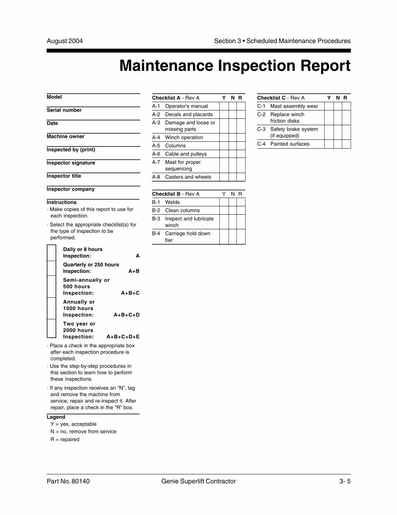
Maintenance Inspection Report
Model
Serial number
Date
Machine owner
Inspected by (print)
Inspector signature
Inspector title
Inspector company
Checklist A - Rev A Y N R
A-1 Operator's manual
A-2 Decals and placards
A-3 Damage and loose ormissing parts
A-4 Winch operation
A-5 Columns
A-6 Cable and pulleys
A-7 Mast for propersequencing
A-8 Casters and wheels
Checklist B - Rev A Y N R
B-1 Welds
B-2 Clean columns
B-3 Inspect and lubricatewinch
B-4 Carriage hold downbar
Checklist C - Rev A Y N R
C-1 Mast assembly wear
C-2 Replace winchfriction disks
C-3 Safety brake system(if equipped)
C-4 Painted surfaces
Instructions· Make copies of this report to use for
each inspection.
· Select the appropriate checklist(s) forthe type of inspection to beperformed.
Daily or 8 hoursInspection: A
Quarterly or 250 hoursInspection: A+B
Semi-annually or500 hoursInspection: A+B+C
Annually or1000 hoursInspection: A+B+C+D
Two year or2000 hoursInspection: A+B+C+D+E
· Place a check in the appropriate boxafter each inspection procedure iscompleted.
· Use the step-by-step procedures inthis section to learn how to performthese inspections.
· If any inspection receives an “N”, tagand remove the machine fromservice, repair and re-inspect it. Afterrepair, place a check in the “R” box.
LegendY = yes, acceptableN = no, remove from service
R = repaired

August 2004
3- 6 Genie Superlift Contractor Part No. 80140
Section 3 • Scheduled Maintenance Procedures
REV AChecklist A Procedures
A-1Perform Pre-operation InspectionCompleting a Pre-operation Inspection is essentialto safe machine operation. The Pre-operationInspection is a visual inspection performed by theoperator prior to each work shift. The inspection isdesigned to discover if anything is apparentlywrong with a machine before the operator performsthe function tests. The Pre-operation Inspectionalso serves to determine if routine maintenanceprocedures are required.
Complete information to perform this procedure isavailable in the appropriate operator's manual.Refer to the Operator's Manual on your machine.
A-2Perform Function TestsCompleting the function tests is essential to safemachine operation. Function tests are designed todiscover any malfunctions before the machine isput into service. A malfunctioning machine mustnever be used. If malfunctions are discovered, themachine must be tagged and removed fromservice.
Complete information to perform this procedure isavailable in the appropriate operator's manual.Refer to the Operator's Manual on your machine.
August 2004 Section 3 • Scheduled Maintenance Procedures
Part No. 80140 Genie Superlift Contractor 3- 7
REV AChecklist B Procedures
B-1Inspect All WeldsWeld inspections are essential to safe machineoperation and good machine performance. Failureto locate and repair damage may result in anunsafe operating condition.
1 Visually inspect the welds in the followinglocations:
· Winch mounting plate
· Loading wheels/steer handle
· Base
· Legs and stabilizers
· Load handling attachment(s)
B-2Clean the Columns
Clean columns are essential to good machineperformance and safe operation. Extremely dirtyconditions may require that the columns becleaned more often.
1 Raise all columns to full height.
2 Visually inspect the inner and outer channels ofthe columns for debris or foreign material. Ifnecessary, use a mild cleaning solvent to cleanthe columns.
Bodily injury hazard. Thisprocedure will require the use ofadditional access equipment. Donot place ladders or scaffold on oragainst any part of the machine.Performing this procedure withoutthe proper skills and tools couldresult in death or serious injury.Dealer service is stronglyrecommended.

August 2004
3- 8 Genie Superlift Contractor Part No. 80140
Section 3 • Scheduled Maintenance Procedures
REV ACHECKLIST B PROCEDURES
B-3Inspect and Lubricate the Winch
Maintaining the winch is essential to good machineperformance and safe operation. An unsafeworking condition exists if the winch has excessivewear and/or does not operate smoothly, free ofhesitation and binding.
1 Carefully lubricate the following areas withautomotive grease:
· Cable drum gear
· Teeth on the pinion gear that mesh withthe cable drum gear
· Threads on the pinion shaft, under thepinion gear
· Models with two speed winch: The teeth onthe slow and the fast speed gears where theymesh together
Do not apply grease to brakefriction disks or rachet gear.
2 Carefully lubricate both pivot points on eachratchet pawl with 30W oil.
3 Measure each friction disk for wear. Replacethe friction disk if it measures less thanspecification.
Friction disk specification
Friction disk 1/16 inch 1.5 mm
4 Measure both shaft bushings for wear. Replacethe bushings if the wall thicknessmeasurements are less than specification.
Pinion shaft bushing specification
Pinion shaft bushing 1/8 inch3.1 mm
5 Lubricate the surface of the frame drum spacerwith a thin layer of lithium grease. Tighten thedrum bolt to 20 ft-lbs / 27 Nm. Do notovertighten.

August 2004 Section 3 • Scheduled Maintenance Procedures
Part No. 80140 Genie Superlift Contractor 3- 9
REV A
B-4Inspect the Carriage Hold-downBarDetection of damage to the column hold downsystem is essential for safe machine operation. Anunsafe working condition exists if the system isdamaged and does not operate properly.
1 Using proper lifting techniques, lay the machineback against a sawhorse or other suitablesupport.
2 Visually inspect the carriage hold-down bar fordamage
3 Check the carriage hold-down bar for smoothoperation.
CHECKLIST B PROCEDURES

August 2004
3- 10 Genie Superlift Contractor Part No. 80140
Section 3 • Scheduled Maintenance Procedures
REV A
C-2Inspect the Mast Assembly for Wear
Detection of excessive or unusual wear in the mastassembly is essential for safe machine operation.An unsafe working condition exists if the mastassembly has excessive wear and/or does notoperate smoothly, free of hesitation and binding.
1 Attach a lifting strap from an overhead crane orsimilar lifting device to the lifting point on the topof the mast. Rotate the carriage hold-down barover the carriage and operate the winch toapply tension to the lifting cable.
2 Lift the machine slightly with the overheadcrane and guide it onto a suitable structurecapable of supporting it.
Crushing hazard. The machine willfall if not properly supported by theoverhead crane.
3 Lower the top of the mast onto the suitablestructure.
4 Attach a lifting strap from an overhead crane tothe base of the machine.
5 Lift the base with the overhead crane, until themast is level and place another suitablestructure under the mast.
6 Lower the base end of the machine.
7 Rotate the mast assembly until the carriage ison top.
Checklist C Procedures
C-1Lubricate the Casters and Wheels
Extremely dirty conditions may require that thecasters and wheels be inspected and lubricatedmore often.
1 Visually inspect each caster and wheel for cuts,cracks or unusual wear.
2 Move the machine on a flat smooth surface andcheck that the casters and wheels rollsmoothly, free of hesitation and binding.
3 Pump grease into the caster or wheel until itcan been seen coming out of the bearing gap.
Grease Type Lithium-based

August 2004 Section 3 • Scheduled Maintenance Procedures
Part No. 80140 Genie Superlift Contractor 3- 11
REV A
8 Visually inspect the top of each column forclearance between the roller wheel and theadjacent column surface.
Result: There should be a gap of less than0.062 inch / 1.57 mm between the roller wheeland the column.
If the mast inspection results in ameasurement that is not withinspecification, replace the rollerwheels. See Repair procedure 2-1, How to Disassemble the MastAssembly.
9 Visually inspect the bottom of each column forclearance between the roller wheel and theadjacent column surface.
Result: There should be a gap of less than0.062 inch / 1.57 mm between the roller wheeland the column.
If the mast inspection results in ameasurement that is not withinspecification, replace the rollerwheels. See Repair procedure 2-1, How to Disassemble the MastAssembly.
3 Grasp the bottom of the carriage and lift itapproximately 12 inches / 30.5 cm, thenrelease the carriage.
Result: The carriage should stop within 5 to 8inches / 12.7 to 20.3 cm and the safety brakeshould engage.
Crushing hazard. Do not standdirectly under the carriage or loadhandling attachment.
CHECKLIST C PROCEDURES
C-3Replace the Winch Friction Disks
Maintaining the winch is essential to good machineperformance and safe operation. An unsafeworking condition exists if the winch has excessivewear and/or does not operate smoothly, free ofhesitation and binding.
1 Replace the winch friction disks. See Repairprocedure 3-1 How to Disassemble a OneSpeed Winch, or 3-2, How to Disassemble aTwo Speed Winch.

August 2004
3- 12 Genie Superlift Contractor Part No. 80140
Section 3 • Scheduled Maintenance Procedures
REV A
C-4Inspect the Safety Brake System(if equipped)
Detection of damage or a faulty safety brakesystem is essential for safe machine operation. Anunsafe working condition exists if the system isdamaged or faulty and does not allow the mast tosequence properly, free of hesitation and binding.
Bodily injury hazard. Thisprocedure requires specific repairskills and a suitable workshop.Attempting this procedure withoutthese skills could result in death orserious injury or significantcomponent damage. Dealerservice is strongly recommended.
Bodily injury hazard. Wearprotective gloves when performingthis procedure.
1 Fasten a load handling attachment to thecarriage (use the forks or the boom if possible).Do not place any weight on the load handlingattachment.
2 Raise the carriage until it is half way up the frontcolumn
CHECKLIST C PROCEDURES
3 Grasp the bottom of the carriage and lift itapproximately 12 inches / 30.5 cm, thenrelease the carriage.
Result: The carriage should stop within 5 to 8inches / 12.7 to 20.3 cm and the safety brakeshould engage.
Crushing hazard. Do not standdirectly under the carriage or loadhandling attachment.
4 Raise the carriage approximately12 inches / 30 cm to disengage the safetybrake.
5 Operate the winch until the front column is halfway up the adjacent column.
6 Grasp the bottom of the front column and lift itapproximately 5 inches / 12 cm, then releasethe column.
Result: The carriage should stop within 5 to 8inches / 12 to 20 cm and the safety brakeshould engage.
Crushing hazard. Do not standdirectly under the columns or loadhandling attachment.
August 2004 Section 3 • Scheduled Maintenance Procedures
Part No. 80140 Genie Superlift Contractor 3- 13
REV A CHECKLIST C PROCEDURES
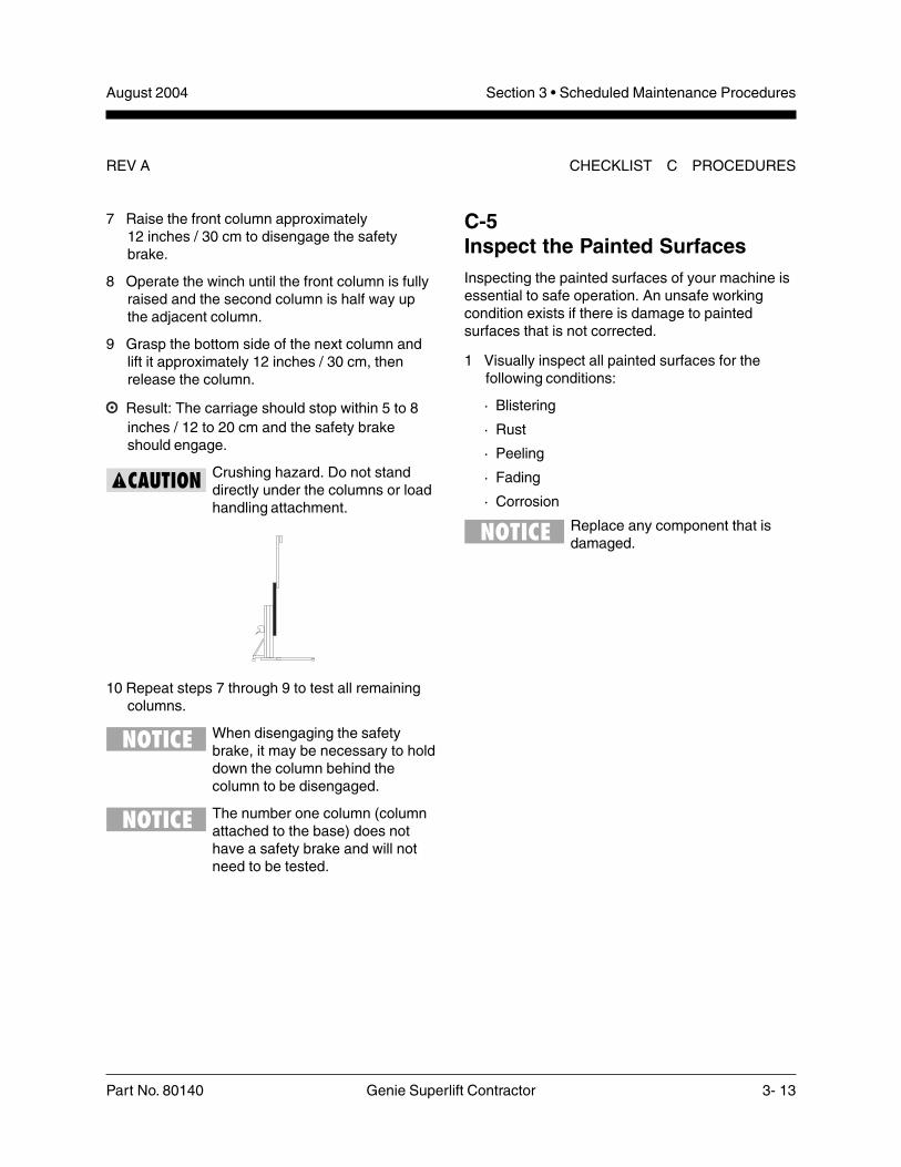
C-5Inspect the Painted SurfacesInspecting the painted surfaces of your machine isessential to safe operation. An unsafe workingcondition exists if there is damage to paintedsurfaces that is not corrected.
1 Visually inspect all painted surfaces for thefollowing conditions:
· Blistering
· Rust
· Peeling
· Fading
· Corrosion
Replace any component that isdamaged.
7 Raise the front column approximately12 inches / 30 cm to disengage the safetybrake.
8 Operate the winch until the front column is fullyraised and the second column is half way upthe adjacent column.
9 Grasp the bottom side of the next column andlift it approximately 12 inches / 30 cm, thenrelease the column.
Result: The carriage should stop within 5 to 8inches / 12 to 20 cm and the safety brakeshould engage.
Crushing hazard. Do not standdirectly under the columns or loadhandling attachment.
10 Repeat steps 7 through 9 to test all remainingcolumns.
When disengaging the safetybrake, it may be necessary to holddown the column behind thecolumn to be disengaged.
The number one column (columnattached to the base) does nothave a safety brake and will notneed to be tested.

August 2004
3- 14 Genie Superlift Contractor Part No. 80140
Section 3 • Scheduled Maintenance Procedures
This page intentionally left blank.

August 2004 Section 4 • Troubleshooting Flow Charts
Part No. 80140 Genie Superlift Contractor 4- 1
Observe and Obey:
Troubleshooting and repair procedures shall becompleted by a person trained and qualified onthe repair of this machine.
Immediately tag and remove from service adamaged or malfunctioning machine.
Repair any machine damage or malfunctionbefore operating the machine.
Be sure the capacities of sawhorses or othersupports are sufficient to withstand machineweight. See Specifications section for specificweight.
Be sure overhead cranes or other lifting devicesare of ample capacity to handle machineweight. See Specification section for specificweight.
Before Troubleshooting:
Read, understand and obey the safety rulesand operating instructions printed in the GenieSuperlift Contractor Operator's Manual.
Be sure that all necessary tools and testequipment are available and ready for use.
Read each appropriate flow chart thoroughly.Attempting shortcuts may produce hazardousconditions.
Be aware of the following hazards and followgenerally accepted safe workshop practices.
Crushing hazard. When testing orreplacing the primary component,always support the structure andsecure it from movement.
Perform all troubleshooting on afirm level surface.
Two people will be required tosafely perform sometroubleshooting procedures.
Troubleshooting Flow Charts
About This SectionWhen a malfunction is discovered, the flow chartsin this section will help a service professionalpinpoint the cause of the problem. To use thissection, basic hand tools are required.
General Repair Process
Malfunctiondiscovered
Identifysymptoms
Troubleshoot
Performrepair
Return toservice problem
solved
problemstill exists
Inspectand test

August 2004Section 4 • Troubleshooting Flow Charts
4- 2 Genie Superlift Contractor Part No. 80140
Mast Will NotSequenceProperlyBe sure safetybrake (if equipped)is not engaged byfully raising andlowering allcolumns.
Impropersequencing of themast columns mayoccur when themachine is at ornear maximumcapacity. If impropersequencing occurs,the columns mayshift to their correctposition duringoperation or whenthe load is removed.The forks will notchange position ifthe columns shiftposition. Thecarriage shouldalways raise first,and lower last.
Chart 1
Verify weight of loadagainst machinecapacity.
over-loaded Remove excess weight
from machine andre-check.
not over-loaded
Check position of loadfor proper centering.
notcentered Center load and
re-check.
centered
Check for cable bindingon cable pulleys.
binding Inspect pulley and pulleyguard for damage.
no Inspect cable fordamage.
yes
Replace the cable. SeeRepair procedure 2-2,How to Replace theLifting Cable.
yes
Replace the pulley orpulley guard. SeeRepair procedure 2-3,How to Replace theLifting Pulley - MastInstalled.
not binding
Inspect the columnchannels and pulleytracks for foreign debris.
debris Clean the columns. SeeMaintenance procedureB-2, Clean the Columns.
no debris
Check the roller wheelsfor damage OR nogrease.
yes Replace the damagedroller wheel(s) OR applygrease to the roller bolt.
no
Check each mastcolumn for damage.
yes Replace the damagedcolumn OR consult theGenie Industries ServiceDepartment.no
Consult the GenieIndustries ServiceDepartment.
REV A

August 2004 Section 4 • Troubleshooting Flow Charts
Part No. 80140 Genie Superlift Contractor 4- 3
Chart 2
Carriage WillNot Raise,But WinchWill OperateBe sure the carriagehold-down bar is notengaged.
Check for broken cable. yes Replace broken cable.See Repair procedure2-2, How to Replace theLifting Cable.
Check all cable pulleysto verify that the cable isproperly routed.
incorrect Inspect the cable forkinks, frays anddamage.
bad Replace damagedcable. See Repairprocedure 2-2, How toReplace the LiftingCable. Check pulley andguard for damage andreplace if needed.
good
Check pulley and pulleyguard for damage.
bad Replace damagedcomponent.
good
Re-install cable(if removed duringinspection).
correct
Inspect winch drum andpinion gear for damage.
bad Replace damagedcomponents OR contactthe Genie IndustriesService Department.good
Contact the GenieIndustries ServiceDepartment.
no
REV A

August 2004Section 4 • Troubleshooting Flow Charts
4- 4 Genie Superlift Contractor Part No. 80140
Chart 3
Winch WillNot Operate
Is the load centeredproperly and free ofobstructions?
no Re-position load toeliminate obstruction. Besure load is properlycentered.
yes
Check the cable forbinding at the winchdrum or inside the mastassembly.
bindingRemove the boundcable and inspect thecable and relatedcomponents fordamage.
bad Replace the damagedcomponent(s).
not binding
Check winch for properoperation. SeeMaintenance procedureA-4, Check the WinchOperation.
badReplace the damagedcomponent. See Repairprocedure 3-1, How toDisassemble a OneSpeed Winch, or 3-2,How to Disassemble aTwo Speed Winch.
good
Check carriage andmast for damagedcolumn(s).
bad Replace damagedcolumn OR consult theGenie Industries ServiceDepartment.
good
Consult the GenieIndustries ServiceDepartment.
REV A

August 2004 Section 5 • Repair Procedures
Part No. 80140 Genie Superlift Contractor 5- 1
Repair Procedures
About This SectionMost of the procedures in this section should onlybe performed by a trained service professionalin a suitably equipped workshop. Select theappropriate repair procedure after troubleshootingthe problem.
Perform disassembly procedures to the pointwhere repairs can be completed. To re-assemble,perform the disassembly steps in reverse order.
Symbols Legend
Safety alert symbol—used to alertpersonnel to potential personalinjury hazards. Obey all safetymessages that follow this symbolto avoid possible injury or death.
Red—used to indicate thepresence of an imminentlyhazardous situation which, if notavoided, will result in death orserious injury.
Orange—used to indicate thepresence of a potentiallyhazardous situation which, if notavoided, could result in death orserious injury.
Yellow with safety alert symbol—used to indicate the presence of apotentially hazardous situationwhich, if not avoided, may causeminor or moderate injury.
Yellow without safety alertsymbol—used to indicate thepresence of a potentiallyhazardous situation which, if notavoided, may result in propertydamage.
Green—used to indicate operationor maintenance information.
Indicates that a specific result is expected afterperforming a series of steps.
Observe and Obey:
Repair procedures shall be completed by aperson trained and qualified on the repair of thismachine.
Immediately tag and remove from service adamaged or malfunctioning machine.
Repair any machine damage or malfunctionbefore operating the machine.
Before Repairs Start:
Read, understand and obey the safety rulesand operating instructions in the Genie SuperliftContractor Operator's Manual.
Be sure that all necessary tools and parts areavailable and ready for use.
Be sure the capacities of sawhorses or othersupports are sufficient to withstand machineweight. See Specifications section for themachine weight.
Be sure overhead cranes or other lifting devicesare of ample capacity to handle machineweight. See Specifications section for specificweight.
Read each procedure completely and adhere tothe instructions. Attempting shortcuts mayproduce hazardous conditions.
Unless otherwise specified, perform eachprocedure with the machine in the followingconfiguration:
· Machine positioned on a firm, level surface
· Carriage fully lowered
· Casters locked

August 2004Section 5 • Repair Procedures
5- 2 Genie Superlift Contractor Part No. 80140
Base Assembly
1-1Base
How to Remove the Base1 Fully lower the carriage.
2 Remove the load handling attachment from themachine.
Models with stabilizers:
3 Remove the mounting fasteners from thestabilizer mounting bracket on the back of themast.
4 Remove the mounting fastener from eachstabilizer at the base. Remove each stabilizerfrom the machine.
All Models:
5 Using proper lifting techniques, tilt the machineback and rest the loading wheels against asuitable structure cable of supporting it.
Bodily injury hazard. Use properlifting techniques when rolling themast assembly over.
6 Remove the mounting fastener and retaining pinfrom each leg. Remove the legs from themachine.
7 Using proper lifting techniques, carefuly tilt themachine to the upright position.
Bodily injury hazard. Use properlifting techniques when tilting themachine to the upright position.
8 Attach a lifting strap from an overhead crane tothe lifting eye at the top of the number one mastcolumn.
9 Position a suitable structure capable ofsupporting the machine on the carriage side ofthe mast.
10 Carefully lift the machine slightly with theoverhead crane. While lowering it, guide themachine over onto a suitable structure capableof supporting it.
Crushing hazard. The machinemay become unbalanced and fallif not properly supported by theoverhead crane.
REV A

August 2004 Section 5 • Repair Procedures
Part No. 80140 Genie Superlift Contractor 5- 3
Mast Assembly
2-1Mast Assembly
How to Disassemble theMast Assembly
Removal of the base is onlynecessary when the number onecolumn is to be removed. See 1-1,How to Remove the Base.
1 Fully lower the carriage and remove the loadhandling attachment.
2 Remove the cable retaining fasteners from thewinch drum. Remove all of the cable from thedrum.
3 Lift the machine slightly with an overheadcrane. While tilting backwards with the carriagefacing up, guide the machine over onto asuitable structure.
Bodily injury hazard. Use properlifting techniques when lifting themast assembly.
Crushing hazard. The machinemay become unbalanced and fallif not properly supported when themast is lifted
4 Remove the mounting fastener from the cableanchor at the top of the last column (carriageside).
11 Secure the top of the mast to the support.
12 Attach a lifting strap from an overhead crane tothe base and lift the machine to a horizontalposition. Slide a second suitable structurecapable of supporting it under the mast, next tothe base.
Crushing hazard. The machinecould become unbalanced and fallif not properly supported by theoverhead crane when the mast islifted.
13 Remove the mounting fasteners from both mastbraces at the base.
14 Remove the base mounting fasteners. Removethe base from the machine.
When installing the base, be surethat the mast and the base aresquare.
REV A

August 2004Section 5 • Repair Procedures
5- 4 Genie Superlift Contractor Part No. 80140
MAST ASSEMBLY REV A
5 Remove the cable from the mast by pulling onthe cable anchor end of the cable.
Bodily injury hazard. Cables canfray. Always wear adequate handprotection when handling cable.
6 Slide the carriage up approximately12 inches / 30 cm to expose the column stopmounting fastener, attached to the bottom endof the top column. Remove the fasteners andthe column stop.
7 Models with safety brake: Insert a hex keywrench through the access holes in thecarriage to release the safety brake. Positionthe hex key above the safety brake rollers.Slide the carriage away from the base whilepulling back on the wrench.
8 Models with safety brake: Remove thecarriage by sliding it out the bottom of the masttoward the base while holding the safety brakerollers in the released position with the hex keywrench.
Models without safety brake: Remove thecarriage by sliding it out the bottom of the masttoward the base.
9 Slide the column up approximately12 inches / 30 cm to expose the column stopmounting fasteners attached to the bottom endof the top column. Remove the fasteners andthe column stops.
10 Models with safety brake: Insert a hex keywrench through the access holes in the columnup to release the safety brake. Position the hexkey above the safety brake rollers. Slide thecarriage away from the base while pulling backon the wrench.
11 Models with safety brake: Remove thecolumn by sliding it out the bottom of the masttoward the base while holding the safety brakerollers in the released position with the hex keywrench.
Models without safety brake: Remove thecolumn by sliding it out the bottom of the masttoward the base.
12 Repeat steps 10 through 12 for each remainingcolumn.
a Brake rollerb Brake release toolc Column or carriage

August 2004 Section 5 • Repair Procedures
Part No. 80140 Genie Superlift Contractor 5- 5
How to Release the Safety BrakeWhen Servicing the MastThe safety brake system can engage when themachine is tilted horizontally if the hold-down bar isnot used. When the brake is engaged, the columnscan extend but not retract. If the safety brakesystem engages while you are servicing the mast,use one of the following methods described belowto release the brake.
Method A: This method allows you to releaseeach column in sequence, starting at thecarriage and removing columns one at a time.See 2-1, How to Disassemble the MastAssembly.
Method B: This method allows you to release anycolumn in the assembly regardless of it'sposition, but requires a custom tool. The tool isa piece of 1/8 to 5/16 inch diameter stiff wirebent in an L shape with one end 1 inch long andthe other end 16 inches long. The installation ofa handle on the long end will make it easier touse. This tool is available from The GenieIndustries Service Parts Department (Geniepart number 33875).
Insert the tool from the bottom of the columninto the safety brake access slot in the innerside wall of the column. Reach through the farupper end of the slot and position the short endof the tool above the safety brake rollers. Slidethe carriage away from the base while pullingback on the tool.
How to Assemble the Mast1 Inspect all mast parts for wear and damage.
Replace as necessary.
2 Clean all columns and rollers.
3 Clean all safety brake assemblies (if equipped).
4 Position the number one column so that it isopen-side up and level. If it is not attached tothe base, secure the column to the supports.
5 Install all column assembly components(removed during disassembly) except thecolumn down stops. Apply a small amount ofmulti-purpose grease between the roller bolthead and the inside of the roller wheel.
6 Slide the number two column into the numberone from the bottom. Stop inserting the columnwhen the top of the up stop or the safety brakeassembly is even with the bottom edge of thenumber one column.
7 Repeat steps 4 through 6 with all remainingcolumns. Do not install the carriage.
The cable is installed after allcolumns are together as anassembly.
8 Attach the swaged end of the cable to the cableanchor on the top of the front column.
REV A MAST ASSEMBLY
August 2004Section 5 • Repair Procedures
5- 6 Genie Superlift Contractor Part No. 80140
MAST ASSEMBLY REV A
14 Apply Loctite® removeable thread sealant tothe pulley mounting fastener and install thelower pulley into the column.
15 Push the cable between the two mast sectionsuntil it comes out the top of the column.
16 Repeat steps 11 through 15 with all remainingcolumns.
17 Slide all the columns forward, until you caninstall the column stops. Do not slide thecolumns forward any farther than necessary.
18 Install all the components removed duringdisassembly.
Be sure that all fasteners haveLoctite® removeable threadsealant applied to the threads andthat all fasteners have beensecurely tightened.
19 Attach the cable to the winch and be sure thecable is routed correctly.
20 Raise the machine to full height to release thesafety brakes (if equipped) and verify properoperation.
9 Feed the other end of the cable through the boxsection (web) of the carriage into the pulley,then push the cable through the pulley until itcomes out the back side of the carriage.
Bodily injury hazard. Cables canfray. Always wear adequate handprotection when handling cable.
Refer to Figure 8-D in the PartsSection to identify the cablerouting.
10 Insert the carriage into the bottom end of the topcolumn. Hold the carriage in place and pull thecable up to the top of the column, leavingenough slack to feed the cable through the nextpulley.
11 Push the cable through the exposed portion ofthe pulley at the top of the column until thecable reaches the pulley at the bottom of thecolumn.
12 Remove the lower pulley assembly from theupper column.
13 Route the cable into and around the lowerpulley.

August 2004 Section 5 • Repair Procedures
Part No. 80140 Genie Superlift Contractor 5- 7
2-2Lifting Cable
How to Replace the Lifting CableBodily injury hazard. Cables canfray. Always wear adequate handprotection when handling cable.
All Genie replacement cablescome with one pre-swaged endthat terminates at the top of thelast column and one taped endthat terminates at the winch.
For additional information, refer toinstructional video, Genie SuperliftCabling Procedure. This video isavailable from The GenieIndustries Service PartsDepartment (Genie partnumber 52701).
1 Fully lower the carriage.
2 Remove the retaining fasteners from the eyeletend of the cable at the mast anchor plate andcut the eyelet off below the copper sleeve.
REV A MAST ASSEMBLY
3 Remove the old cable from the winch drum.
4 Unwind the outer strands and trim them back1/2 inch / 12.7 mm leaving the core longer.Repeat this process on the open end of the newcable.
5 Using the cable threading tool supplied withyour cable, insert even amounts of cable intoeach end of the tool. Tighten the set screws.
6 Place a smooth layer of strapping tape over thejoint section of the two cables and the tool.
If the cable gets caught as you arepulling it through the columns andpulleys, avoid pulling too hard asyou may break the connectionbetween the two cables. Trypulling the cable back and forthuntil the cable pulls freely.
7 Wind the old cable onto the winch drum whilefeeding the new cable through machine.

August 2004Section 5 • Repair Procedures
5- 8 Genie Superlift Contractor Part No. 80140
2-3Lifting Pulley
How to Replace a Lifting Pulley-Mast Installed1 Fully lower the carriage.
2 Unwind approximately 1 to 2 feet / 30 to 61 cmof cable from the winch drum.
3 Tip the machine backwards and rest the top ofthe number one mast on a suitable structurecapable of supporting it. Secure the top of themast to the structure.
4 Attach an overhead crane to the base. Lift themachine to a horizontal position and slide asecond structure under the mast next to thebase.
5 If replacing an upper pulley, slide the columnthat is above the pulley to be replaced forward.If replacing a lower pulley, slide the column withthe pulley to be replaced forward. Push thecolumn forward approximately 6 inches / 15 cmto expose the lower column stop.
6 Remove the column stop mounting fasteners.
7 Slide the column backwards until the pulley thatis to be replaced is exposed.
MAST ASSEMBLY
8 When the taped area appears at the winch,loosen the set screws and remove the old cablefrom the winch drum.
9 Attach the new cable to both the mast anchorand the winch drum.
10 Wind the new cable evenly onto the winchdrum. Be sure there are at least four wraps ofcable on the winch drum.
11 Fully raise and lower the carriage without a loadto check for proper operation. The carriageshould raise and lower smoothly.
12 Fully raise and lower the carriage again with aload and check for proper operation. Thecarriage should raise and lower smoothly.
Do not use as a load carryingcable splice. This tool is intendedfor cable replacement only.
REV A

August 2004 Section 5 • Repair Procedures
Part No. 80140 Genie Superlift Contractor 5- 9
MAST ASSEMBLY
8 Remove the two mounting fasteners from thepulley mounting block. Remove the pulleyassembly.
9 Remove the retaining fastener that attaches thepulley to the mounting block.
Note the quantity and location ofthe shims and spacers beforedisassembling.
10 Remove the old pulley.
11 Install the cable onto the new pulley.
12 Apply Loctite® removeable thread sealant tothe pulley mounting fastener and install thefastener through the pulley and pulley guardinto the pulley mounting block.
a Pulleyb Pulley guardc Pulley mounting block
Crushing hazard. Failure toproperly route the cable couldresult in a winch brake failure.
Component damage hazard.Do not allow the cable to becometwisted during installation or mastsequencing problems may occur.
Be sure the cable guard is locatedover the retaining pin on the pulleymounting block. Be sure the pulleyspins freely after reassembling thepulley assembly.
13 Apply Loctite® removeable thread sealant tothe fastener and install the pulley assemblyonto the column.
REV A

August 2004Section 5 • Repair Procedures
5- 10 Genie Superlift Contractor Part No. 80140
Winches
7 Slide the pinion shaft to the right and removethe pinion spacer, pinion plate, ratchet gear andfriction disks. Turn the pinion gearcounterclockwise and slide it off the left side ofthe shaft.
8 Remove the pinion shaft from the winchhousing.
9 Remove both pinion bushings. Use a soft metaldrift equal to the outside diameter of thebushing and tap with a rubber mallet.
Component damage hazard.Place a block in between the wallsof the winch housing to preventthe housing from bending whileremoving the bushings.
10 Remove the winch housing from the machine.
3-1One Speed Winch
How to Disassemble a One SpeedWinch
Bodily injury hazard. Cables canfray. Always wear adequate handprotection when handling cable.
1 Fully lower the carriage.
2 Remove the cable retaining fastener from thewinch drum. Remove the cable from the winchdrum.
3 Remove both handle retaining fasteners.Remove the handles from the pinion shaft.
4 Remove the drum bolt and the drum boltspacer. Remove the drum, drum gear coverand housing spacer from the winch.
5 Remove the two lock nuts from the pinion shaftby holding the opposite end of the shaft at theflattened portion of the threads.
Component damage hazard. Becareful not to damage the threadswhile holding the pinion shaft.
6 Remove the retaining ring from the pinion shaft.
REV A
August 2004 Section 5 • Repair Procedures
Part No. 80140 Genie Superlift Contractor 5- 11
REV A WINCHES
How to Assemble a One SpeedWinch
Bodily injury hazard. Cables canfray. Always wear adequate handprotection when handling cable.
Refer to Figure 8-E, Single SpeedWinch Components, for anexploded view of the winch.
1 Place one side of the winch housing over thejaws of a vise. Open the vise until the jaws arewider than the outside diameter of the bushing.
2 Insert a soft metal drift through the oppositebushing hole. Tap the drift with a rubber malletto push the bushing into place.
3 Repeat steps 1 and 2 to insert the otherbushing.
Use a piece of flatbar or wood inbetween the drift and the bushingto prevent any damage to thebushing.
4 Add two drops of 30W oil to both pivot points oneach ratchet pawl.
Bodily Injury Hazard.Overlubrication of the ratchet pawlmay result in oil coming in contactwith the surface of the winch brakeleading to an unsafe workingcondition. Do not allow any oil onthe brake or pressure plate.
5 Install the winch housing onto the mast. Be surethe winch drum is toward the top.
6 Insert the longer threaded end of the pinionshaft approximately halfway through the leftbushing.
7 Apply a small amount of multi-purpose greaseto the large threaded section of the pinion shaft,under the gear nut. Screw the pinion gear ontothe pinion shaft with the gears toward the leftside of the winch housing.
8 Install, in order, a brake disk, a ratchet gear, abrake disk, a pinion plate and a pinion spaceronto the pinion shaft.
Component damage hazard. Donot allow grease or oil onto thebrake disks or the ratchet gear.
The teeth on the ratchet gear mustcurve away from the right side ofthe winch housing.
9 Push the pinion shaft to the right, through theright pinion bushing, and install the pinion shaftretaining ring.
Use your fingers to push theratchet pawls outward whilepushing the pinion shaft throughthe right bushing. Be sure theratchet pawls are in firm contactwith the ratchet gear and that allparts move freely.
10 Install the two jam nuts to the right side of thepinion shaft one at a time, and tighten.
11 Position both handles on the pinion shaft inopposite directions. Install and tighten the locknuts.
12 Lubricate the outside of the frame spacer with

August 2004Section 5 • Repair Procedures
5- 12 Genie Superlift Contractor Part No. 80140
20 Rotate the drum so that the two square cablekeeper holes are at the top. Install the cablekeeper clip to the outside of the drum with thetwo carriage bolts coming through from theinside. Install the lock washers and nuts fingertight. Do not tighten.
21 Route the end of the cable around the winchdrum and out through the remaining hole on theleft side wall of the drum.
a number one columnb cablec winch drumd cable keeper clip
22 Insert the end of the cable under the cablekeeper clip approximately 1/2 inch / 13 mm andtighten the cable keeper clip fasteners.
23 While holding the cable tight on the drum, rotatethe drum and spool the cable onto the drumevenly.
Component damage hazard. Besure the cable winds onto thewinch drum evenly.
WINCHES REV A
multi-purpose grease. Insert the frame spacerinto the drum.
13 Install the cable drum. Be sure the drum gearsmesh with the ratchet gears.
14 Install the drum bolt keeper. Push the drum boltthrough the winch housing, drum cover anddrum. Be sure the head of the drum bolt is onthe drum gear side of the winch.
15 Place the drum gear cover in position with thedrum bolt slot under the drum bolt keeper.
16 Install the drum bolt jam nut hand tight.
17 Install the housing spacer with the head of thehousing spacer bolt on the right side of thewinch and through the slotted portion of thedrum gear cover. Place the nut on the end ofthe bolt and tighten.
18 Torque the drum bolt nut to20 to 25 ft-lbs / 27 to 34 Nm.
Component damage hazard.Overtightening the drum bolt jamnut may cause damage to theframe spacer and prevent thedrum from spinning freely.
19 Lubricate the teeth of the drum gear and thepinion nut that meshes with the drum gear withmulti-purpose grease.
Bodily Injury Hazard.Overlubrication of the ratchet pawlmay result in oil coming in contactwith the surface of the winch brakeleading to an unsafe workingcondition. Do not allow any oil onthe brake or pressure plate.
a
c
b
d
b

August 2004 Section 5 • Repair Procedures
Part No. 80140 Genie Superlift Contractor 5- 13
REV A WINCHES
8 Slide the input shaft out of the winch housing.
9 Remove the retaining ring from the pinion shaft.
10 Remove the lock nut from the end of the pinionshaft (located on the outside of the winchhousing).
Note the location and position ofthe components on the pinionshaft.
11 Slide the pinion shaft to the right and removethe pinion spacer, pinion plate, ratchet gear,and friction disks. Turn the pinion gearcounterclockwise and slide it off the left side ofthe shaft.
12 Remove both pinion bushings. Use a soft metaldrift equal to the outside diameter of thebushing and tap with a rubber mallet.
Component damage hazard.Place a block between the walls ofthe winch housing to prevent thehousing from bending whileremoving the bushings.
3-2Two Speed Winch
How to Disassemble a TwoSpeed Winch
Bodily injury hazard. Cables canfray. Always wear adequate handprotection when handling cable.
1 Fully lower the carriage and remove the loadhandling attachment.
2 Remove the cable retaining fasteners from thewinch drum. Remove the cable from the drum.
3 Remove both handle retaining fasteners fromthe pinion shaft. Remove the handles.
4 Remove the drum bolt and spacer. Remove thedrum, drum gear cover and housing spacer.
5 Remove the input shaft cover.
6 Remove the mounting fasteners from the springand ball housing.
7 Remove the two springs and balls from thespring and ball housing.

August 2004Section 5 • Repair Procedures
5- 14 Genie Superlift Contractor Part No. 80140
WINCHES REV A
7 Apply a small amount of multi-purpose greaseto the large threaded section of the pinion shaft,under the gear nut. Slide the pinion shaft gearsonto the pinion shaft. Install the pinion gearonto the pinion shaft with the gears toward theright side of the winch housing. Screw ontolarge threads hand tight.
8 Install, in order, a friction disk, a ratchet gear, afriction disk, a pinion plate and a pinion spaceronto the pinion shaft.
Component damage hazard. Donot allow grease or oil onto thebrake disk, ratchet gear or theteflon spacer.
The teeth on the ratchet gear mustcurve toward the left side of thewinch housing.
9 Install the pinion shaft retaining ring onto thepinion shaft.
Use your fingers to push theratchet pawls outwards whilepushing the pinion shaft throughthe left bushing. Be sure theratchet pawls are in firm contactwith the ratchet gear and that allparts move freely.
10 Install the lock nut on the left side of the pinionshaft.
11 Install the input shaft approximately half waythrough the left side of the winch housing.
12 Slide the left side bushing, spring and ballhousing, spacer, input shaft gears and rightside bushing onto the input shaft.
13 Install the ball and spring into the spring andball housing. Install the mounting fasteners.
How to Assemble a Two SpeedWinch
Bodily injury hazard. Cables canfray. Always wear adequate handprotection when handling cable.
See Figure 8-F, Two SpeedWinch, for an exploded view of thewinch.
1 Place one side of the winch housing over thejaws of a vise. Open the vise until the jaws arewider than the outside diameter of the bushing.
2 Insert a soft metal drift through the oppositebushing hole. Line up the tab on the bushing tothe hole in the winch housing. Tap the drift witha rubber mallet to push the bushing into place.
3 Repeat steps 1 and 2 to insert the otherbushing.
Use a piece of flatbar or woodbetween the drift and the bushingto prevent any damage to thebushing.
4 Add two drops of 30W oil to both pivot points oneach ratchet pawl.
Bodily Injury Hazard.Overlubrication of the ratchet pawlmay result in oil coming in contactwith the surface of the winch brakeleading to an unsafe workingcondition. Do not allow any oil onthe brake or pressure plate.
5 Install the winch housing on the mast. Be surethe winch drum is toward the top.
6 Insert the longer threaded end of the pinionshaft approximately halfway through the rightside bushing.
August 2004 Section 5 • Repair Procedures
Part No. 80140 Genie Superlift Contractor 5- 15
14 Lubricate the outside of the frame spacer withmulti-purpose grease and insert it into the drum.
15 Install the cable drum. Be sure the drum gearsmesh with the ratchet gears.
16 Install the drum bolt keeper. Push the drum boltthrough the winch housing, drum cover anddrum. Be sure the head of the drum bolt is onthe drum gear side of the winch.
17 Install the drum bolt jam nut and torqueto 20 to 25 ft-lbs / 27 to 34 Nm.
Component damage hazard.Overtightening the drum bolt jamnut may cause damage to theframe spacer and prevent thedrum from spinning freely.
18 Lubricate the teeth of the drum gear and thepinion nut with multi-purpose grease.
Bodily Injury Hazard.Overlubrication of the ratchet pawlmay result in oil coming in contactwith the surface of the winch brakeleading to an unsafe workingcondition. Do not allow any oil onthe brake or pressure plate.
19 Install the input shaft cover.
20 Rotate the winch drum so that the oblong slot isvisible and horizontal.
21 Install the cable keeper clip on the outside ofthe winch drum with one carriage bolt comingthrough from the inside. Install the lock washerand nut finger tight. Do not tighten the nut.
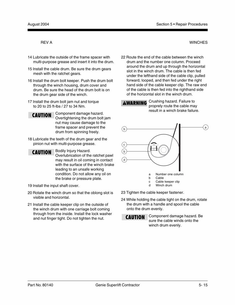
22 Route the end of the cable between the winchdrum and the number one column. Proceedaround the drum and up through the horizontalslot in the winch drum. The cable is then fedunder the lefthand side of the cable clip, pulledforward, looped, and then fed under the righthand side of the cable keeper clip. The raw endof the cable is then fed into the righthand sideof the horizontal slot in the winch drum.
Crushing hazard. Failure toproprely route the cable mayresult in a winch brake failure.
a Number one columnb Cablec Cable keeper clipd Winch drum
23 Tighten the cable keeper fastener.
24 While holding the cable tight on the drum, rotatethe drum with a handle and spool the cableonto the drum evenly.
Component damage hazard. Besure the cable winds onto thewinch drum evenly.
REV A WINCHES
August 2004Section 5 • Repair Procedures
5- 16 Genie Superlift Contractor Part No. 80140
This page intentionally left blank.

Section 6 • DecalsAugust 2004
Part No. 80140 Genie Superlift Contractor 6- 1
DecalsDecalsDecalsDecalsDecals
Section Six

August 2004Section 6 • Decals
6- 2 Genie Superlift Contractor Part No. 80140
Figure 6-ADecals with Words (before serial number SLC04-28241)
One SpeedWinch
Two SpeedWinch
11 1112131415 14
2 432 31
7
16
8
9
10
2
5
6
2
7
8
9
10
REV A

Section 6 • DecalsAugust 2004
Part No. 80140 Genie Superlift Contractor 6- 3
FIGURE 6-A
Item Part No. Description Qty.
— 48373 Decal Kit - Safety/Instructional(includes items 2, 5, 7 - 10 and13) (before serial numberSLC04-28241)
— 84806 Decal Kit, Words (after serialnumber SLC04-28240)
— 84807 Decal Kit, Symbols (after serialnumber SLC04-28240)
1 32775 Warning - Fall Hazard .............. 1
2 33468 Warning - No Riders ................. 4
3 32716 Notice - Boom Setup ................ 2
4 32714 Notice - Adjustable ForkSetup ........................................ 1
5 32687 Warning - Standard ForkSafety ........................................ 1
6 32717 Warning - Boom Safety ............. 1
7 40513 Warning - Machine Safety ........ 1
8 32938 Label - Use this Winch ............. 1
9 32939 Warning - Crushing Hazard,Brake Lock ................................ 1
10 31072 Label - Operator’s ManualStorage Container .................... 1
11 52992 Cosmetic (SLC-6 models) ........ 2— 52993 Cosmetic (SLC-12 models) ........— 52994 Cosmetic (SLC-18 models) ........— 52995 Cosmetic (SLC-24 models) ........
12 52675 Caution - DamagedMachine .................................... 1
13 32885 Warning - Silent Winch ............. 1
14 52984 Cosmetic - SuperliftContractor ................................. 2
15 33982 Plate - Serial Number ............... 1
16 32770 Label - Two Speed Winch ........ 1
REV A

August 2004Section 6 • Decals
6- 4 Genie Superlift Contractor Part No. 80140
Figure 6-BDecals with Words (after serial number SLC04-28240)
32938
Serial Plate
Serial Plate
52984
52984
97547
33468
32687
40513or 33454
97529
32939
32885
32770
31072
5267532717
32716
32714
33468
32775
33468
33468
52992 or52993 or
5299552994 or
52992or 52993
or 52995or 52994
REV A

Section 6 • DecalsAugust 2004
Part No. 80140 Genie Superlift Contractor 6- 5
Item Part No. Description Qty.
1 31072 Decal, Label - Operator’sManual Container ..................... 1
2 32687 Decal, Warning - StandardForks Safety/Setup ................... 1
3 32714 Decal, Warning - AdjustableForks Safety/Setup ................... 1
4 32716 Decal, Notice - Boom Setup ..... 1
5 32717 Decal, Warning - BoomSafety ........................................ 1
6 32770 Decal, Notice - Two-SpeedShift Instructions ....................... 1
7 32775 Decal, Warning - Fall Hazard,Load Platform ........................... 1
8 32885 Decal, Warning - SilentWinch ........................................ 1
9 32938 Decal, Label - Use this Winch .. 1
10 32939 Decal, Warning - Brake Lock .... 1
11 33468 Decal, Warning - No Riders ..... 1
12 33545 Decal, Warning - MachineSafety & Setup (before serialnumber 9596-5288) ................. 1
13 40513 Decal, Warning - MachineSafety & Setup (after serialnumber 9596-5287) ................. 1
14 52675 Decal, Caution - DamagedMachine Hazard ....................... 1
15 52984 Decal, Cosmetic - SuperliftContactor Logo ......................... 2
16 52992 Decal, Cosmetic - SLC-6 .......... 2— 52993 Decal, Cosmetic - SLC-12 ........ 2— 52994 Decal, Cosmetic - SLC-18 ........ 2— 52995 Decal, Cosmetic - SLC-24 ........ 2
17 97529 Decal, Caution - Bodily InjuryHazard ...................................... 1
18 97547 Decal, Danger - ElectrocutionHazard ...................................... 2
FIGURE 6-BREV A

August 2004Section 6 • Decals
6- 6 Genie Superlift Contractor Part No. 80140
Figure 6-CDecals with Symbols
97541
Serial Plate
Serial Plate
52984
52984
97539
97543
82964
82487
97532
97545
97546
82964
82487
82487
82487
82964
82964
52992 or52993 or
5299552994 or
52992or 52993
or 52995or 52994
REV A
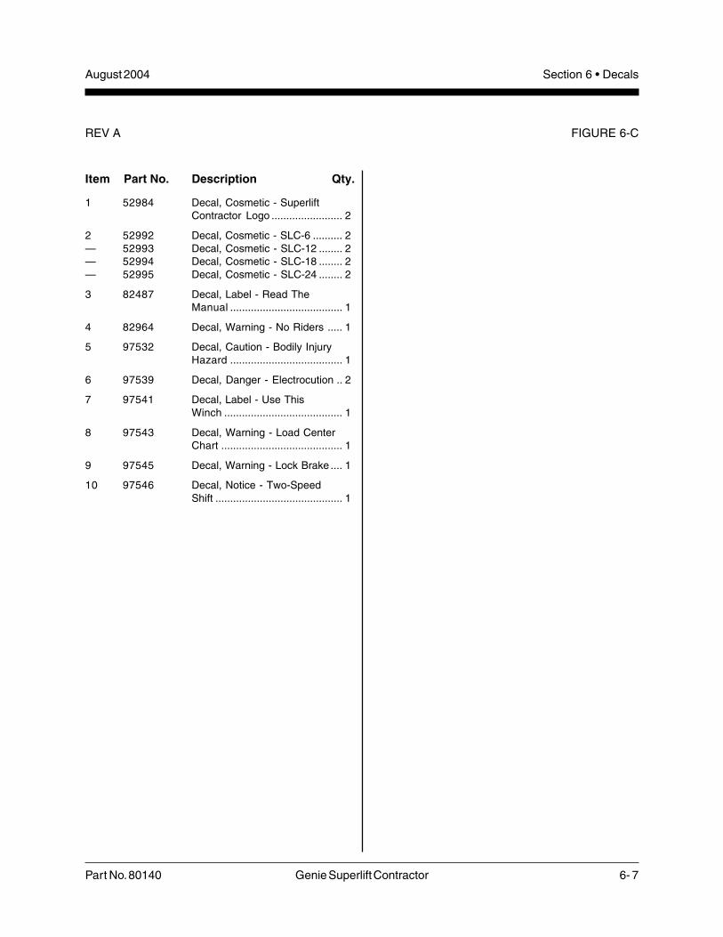
Section 6 • DecalsAugust 2004
Part No. 80140 Genie Superlift Contractor 6- 7
Item Part No. Description Qty.
1 52984 Decal, Cosmetic - SuperliftContractor Logo ........................ 2
2 52992 Decal, Cosmetic - SLC-6 .......... 2— 52993 Decal, Cosmetic - SLC-12 ........ 2— 52994 Decal, Cosmetic - SLC-18 ........ 2— 52995 Decal, Cosmetic - SLC-24 ........ 2
3 82487 Decal, Label - Read TheManual ...................................... 1
4 82964 Decal, Warning - No Riders ..... 1
5 97532 Decal, Caution - Bodily InjuryHazard ...................................... 1
6 97539 Decal, Danger - Electrocution .. 2
7 97541 Decal, Label - Use ThisWinch ........................................ 1
8 97543 Decal, Warning - Load CenterChart ......................................... 1
9 97545 Decal, Warning - Lock Brake .... 1
10 97546 Decal, Notice - Two-SpeedShift ........................................... 1
FIGURE 6-CREV A

August 2004Section 6 • Decals
6- 8 Genie Superlift Contractor Part No. 80140
This page intentionally left blank.

Section 7 • Base ComponentsAugust 2004
Part No. 80140 Genie Superlift Contractor 7- 1
BaseBaseBaseBaseBaseComponentsComponentsComponentsComponentsComponents
Section Seven
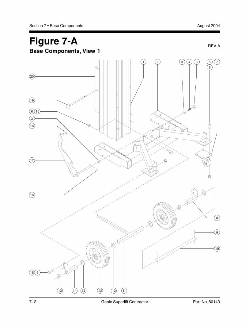
August 2004Section 7 • Base Components
7- 2 Genie Superlift Contractor Part No. 80140
Figure 7-ABase Components, View 1
12 14 12 13 12 11
21 75
6
343
6 15
15 6
20
19
16
17
3
18
9
10
8
REV A

Section 7 • Base ComponentsAugust 2004
Part No. 80140 Genie Superlift Contractor 7- 3
FIGURE 7-A
Item Part No. Description Qty.
1 Ref. Columns (refer to Figure 8-D)
2 80141-S Base Assembly with Decals(SLC-6 models) ............................ 1
— 80142-S Base Assembly with Decals(SLC-12 models)
— 80143-S Base Assembly with Decals(SLC-18 models)
— 80144-S Base Assembly with Decals(SLC-24 models)
3 21443 Shim Washer,0.45 x 0.75 x 0.063 inch ............... 3
4 33658 Hold-down Spring ......................... 1
5 6175 Screw - HHC,3/8 -16 x 1 inch, GR 5
6 4828 Nylock Nut, 3/8 -16
7 57735 Rear Swivel Caster,5 x 1.5 inches ............................... 2
8 33830-S Rear Spacer Mount Bracket,Right Side ..................................... 1
9 6094 Cotter Pin, 0.125 x 1 inch ............. 2
10 57237 Transport Wheels Axle Rod ......... 1
11 33831-S Wheel Spacer ............................... 1
12 6564 Shim Washer,0.75 x 1.125 x 0.093 inch ............. 6
13 35064 Rear Wheel, 10 x 0.75 inch .......... 2
14 33829-S Rear Spacer Mount Bracket,Left Side ....................................... 1
15 6019 Screw - HHC,3/8 -16 x 1.25 inches, GR 5
16 12016 Cotter Pin, 0.125 x 0.75 inch ........ 1
17 58750 Hold-down Assembly with Decal(SLC-6 models) (includes itemnumbers 16 and 18) ..................... 1
— 58095 Hold-down Assembly with Decal(SLC-12 models) (includes items16 and 18) .................................... 1
— 58095 Hold-down Assembly with Decal(SLC-18 models) (includes items16 and 18)
— 58095 Hold-down Assembly with Decal(SLC-24 models) (includes items16 and 18)
Item Part No. Description Qty.
18 11890 Glide Button .................................. 1
19 48301 Toggle Pin, 0.5 x 8.13 inches ....... 1
20 Ref. Carriage (refer to Figure 8-D)
REV A
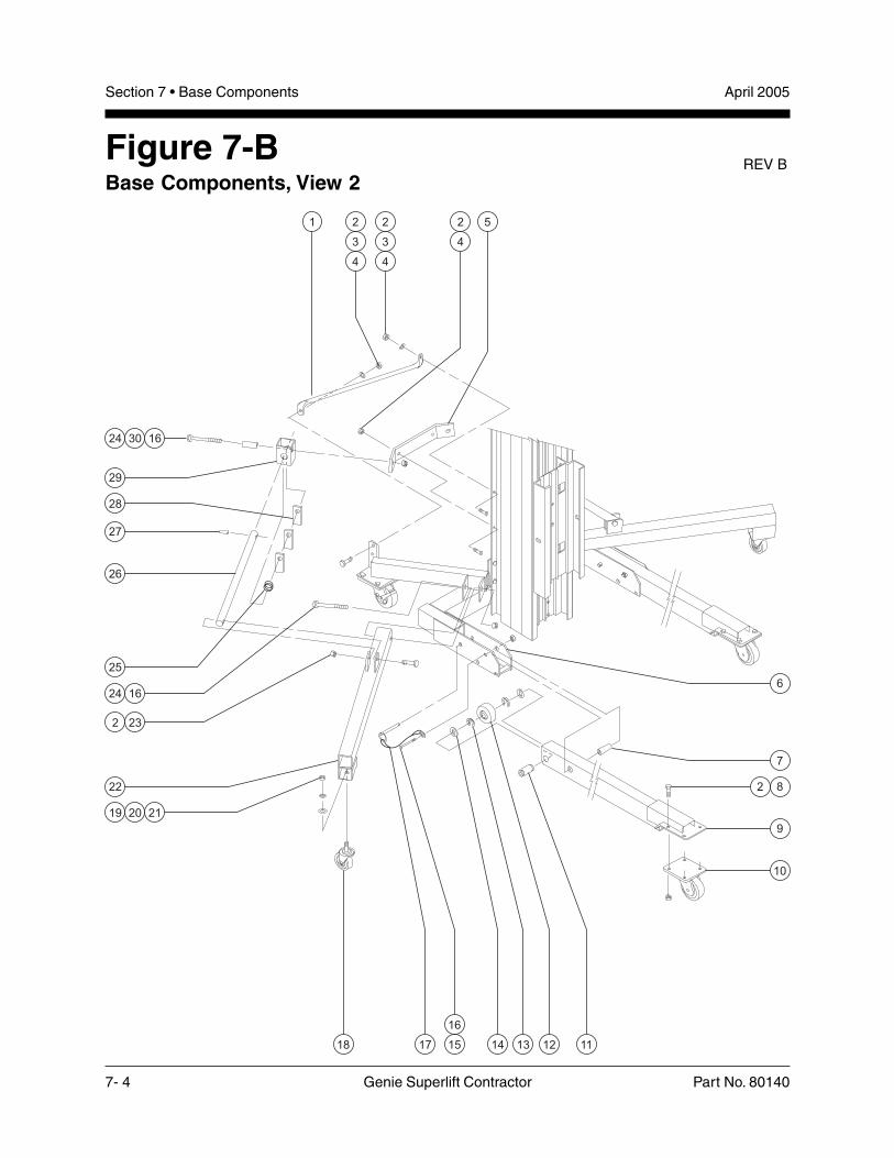
August 2004Section 7 • Base Components
7- 4 Genie Superlift Contractor Part No. 80140
Figure 7-BBase Components, View 2
1 52
4
2
3
4
2
3
4
10
9
7
6
82
19 20 21
24 30 16
2 23
24 16
26
27
28
29
22
25
18 17 14 13 12 1115
16
REV B
April 2005

Section 7 • Base ComponentsAugust 2004
Part No. 80140 Genie Superlift Contractor 7- 5
FIGURE 7-B
Item Part No. Description Qty.
1 32883 Right Side Mast Brace .................. 1— 32884 Left Side Mast Brace
2 4828 Nylock Nut, 3/8 -16
3 6097 Flat Washer, 3/8 inch
4 6019 Screw - HHC,3/8 -16 x 1.25 inches, GR 5
5 35212-S Stabilizer Mount Bracket .............. 1
6 Ref. Base Assembly with Decals(refer to Figure 7-A) ...................... 1
7 32509 Leg Pivot Tube ............................. 2
8 6175 Screw - HHC,3/8 -16 x 1 inch, GR 5
9 35015 Leg Weldment (SLC-6 models) .... 2— 35016 Leg Weldment (SLC-12 models)— 35017 Leg Weldment (SLC-18 models)— 35018 Leg Weldment (SLC-24 models)
10 57734 Front Swivel Caster,4 x 1.5 inches ............................... 2
11 32524 Leg Axle Tube .............................. 2
12 57782 Polyolefin Wheel,2.5 x 1.25 inches .......................... 2
13 32499 E Clip, 0.875 inch ......................... 4
14 33373 Shim Washer,0.938 x 1.5 x 0.09 inch ................. 4
15 10598 Screw - HHC,1/2 -13 x 3 inches, GR 5
16 6086 Low Profile Nylock Nut, 1/2 -13
17 100309 Pin Assembly with Lanyard .......... 2
18 57746 Side Swivel Caster,3.5 x 1.25 inches .......................... 2
19 6034 Hex Jam Nut, 1/2 -13
20 6033 Lock Washer, 1/2 inch
21 6095 Flat Washer, 1/2 inch
22 35019 Stabilizer Bracket ......................... 2
23 5224 Screw - HHC,3/8 -16 x 2 inches, GR 5
24 6732 Screw - HHC,1/2 -13 x 3.25 inches, GR 5
Item Part No. Description Qty.
25 32519 Stabilizer Latch Spring ................. 2
26 58094 Stabilizer Strut Assembly(includes item 27) ......................... 2
27 11337 Roll Pin, 0.25 x 1.25 inches .......... 2
28 32577 Stabilizer Latch Plate .................... 6
29 35213 Stabilizer Tube ............................. 2
30 32576 Stabilizer Pivot Tube .................... 2
REV B
April 2005

August 2004Section 7 • Base Components
7- 6 Genie Superlift Contractor Part No. 80140
This page intentionally left blank.

Section 8 • Mast and Winch ComponentsAugust 2004
Part No. 80140 Genie Superlift Contractor 8- 1
Mast andMast andMast andMast andMast andWWWWWinchinchinchinchinch
ComponentsComponentsComponentsComponentsComponents
Section Eight
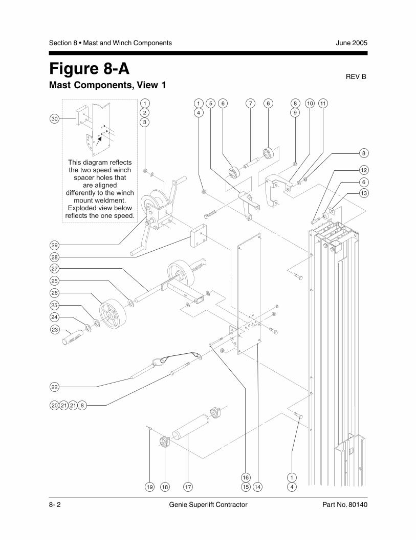
August 2004Section 8 • Mast and Winch Components
8- 2 Genie Superlift Contractor Part No. 80140
Figure 8-AMast Components, View 1
REV B
This diagram reflectsthe two speed winch
spacer holes thatare aligned
differently to the winchmount weldment.
Exploded view belowreflects the one speed.
25
27
28
29
30
26
25
24
23
22
4
1
15
16
171819 14
8
12
6
13
8
9
5 6 7 6 10 11
4
1
2
3
1
20 21 21 8
June 2005

Section 8 • Mast and Winch ComponentsAugust 2004
Part No. 80140 Genie Superlift Contractor 8- 3
FIGURE 8-A
Item Part No. Description Qty.
1 4828 Nylock Nut, 3/8 -16
2 6097 Flat Washer, 3/8 inch(One speed winch) ....................... 1
— 6097 Flat Washer, 3/8 inch(Two speed winch) ....................... 3
3 6326 Screw - HHC, 3/8 -16 x 3 inches,GR 5 (SLC-6 and SLC-12 models)
— 6175 Screw - HHC, 3/8 -16 x 1 inch,GR 5 (SLC-18 and SLC-24 models)
4 6019 Screw - HHC,3/8 -16 x 1.25 inches
5 109579 Mast Stiffener, Right, Gray ........... 1
6 32473 Nylatron Roller,1.75 x 0.72 inch ............................ 2
7 33843 Mast Stiffener Spacer,4.56 x 0.75 inch ............................ 1
8 6198 Nylock Nut, 1/2 -13
9 13005 Screw - HHC,1/2 -13 x 6 inches, GR 8 ................ 1
10 109580 Mast Stiffener, Left, Gray .............. 1
11 6095 Flat Washer, 1/2 inch
12 32475 Roller Bolt,1/2 -13 x 1.84 inches ..................... 2
13 32474 Roller Guard ................................. 2
14 33766 Winch Mount Bracket ................... 1
15 12343 Screw - HHC,1/4 -20 x 3 inches, GR 5
16 6091 Nylock Nut, 1/4 -20 ........................ 1
17 6600 Instruction Tube with Caps ........... 1
18 6653 Rubber Cushioned Clamp,1.88 inches ................................... 2
19 7265 Steel Rivet, 0.25 x 0.375 inch ....... 2
20 6732 Screw - HHC,1/2 -13 x 3.25 inches, GR 5
21 11978 Nylon Flat Washer, 1/2 inch
22 32940 Pin Assembly with Lanyard .......... 1
23 6587 Rubber Grip .................................. 2
Item Part No. Description Qty.
24 33385 Push-on Washer, 0.75 inch .......... 2
25 6564 Shim Washer,0.75 x 1.125 x 0.093 inch
26 57788 Polyolefin Wheel, 6 x 2 inches ..... 2
27 100301 Loading Wheel ............................. 1— 33618 Loading Wheel— 33540 Loading Wheel Assembly w/
Word Decals (includes items23 - 26)
— 35819 Loading Wheel Assembly w/Symbol Decals (includes items23- 26)
28 35834 Winch Spacer, One Speed(SLC-6 and SLC-12 models) ........ 1
29 Ref. Winch Assembly(refer to Figures 8-E or 8-F)
30 49991 Winch Spacer, Two Speed(SLC-6 and SLC-12 models) ........ 1
REV B
June 2005

August 2004Section 8 • Mast and Winch Components
8- 4 Genie Superlift Contractor Part No. 80140
Figure 8-BMast Components, View 2
REV A
10
11
6
12
893
8
5
9
3
8
5
9
10 11
108 11 14 13 1010
4
71
2
3
8
9
3
15
1
5
5
5
5
6
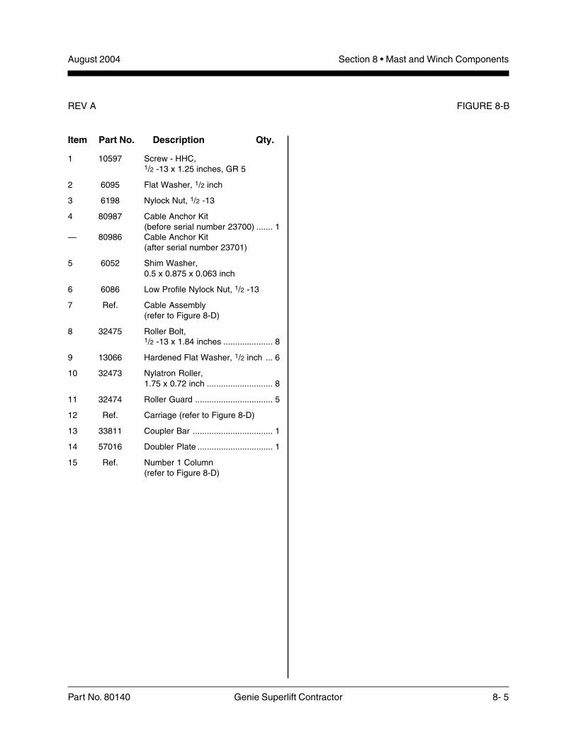
Section 8 • Mast and Winch ComponentsAugust 2004
Part No. 80140 Genie Superlift Contractor 8- 5
FIGURE 8-B
Item Part No. Description Qty.
1 10597 Screw - HHC,1/2 -13 x 1.25 inches, GR 5
2 6095 Flat Washer, 1/2 inch
3 6198 Nylock Nut, 1/2 -13
4 80987 Cable Anchor Kit(before serial number 23700) ....... 1
— 80986 Cable Anchor Kit(after serial number 23701)
5 6052 Shim Washer,0.5 x 0.875 x 0.063 inch
6 6086 Low Profile Nylock Nut, 1/2 -13
7 Ref. Cable Assembly(refer to Figure 8-D)
8 32475 Roller Bolt,1/2 -13 x 1.84 inches ..................... 8
9 13066 Hardened Flat Washer, 1/2 inch ... 6
10 32473 Nylatron Roller,1.75 x 0.72 inch ............................ 8
11 32474 Roller Guard ................................. 5
12 Ref. Carriage (refer to Figure 8-D)
13 33811 Coupler Bar .................................. 1
14 57016 Doubler Plate ................................ 1
15 Ref. Number 1 Column(refer to Figure 8-D)
REV A
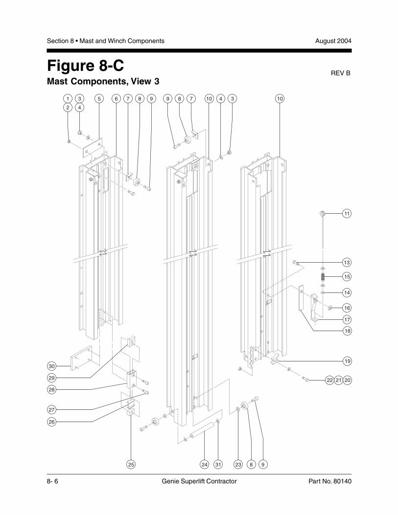
August 2004Section 8 • Mast and Winch Components
8- 6 Genie Superlift Contractor Part No. 80140
Figure 8-CMast Components, View 3
REV B
24 31 23 8 925
5 6 7 8 9 9 8 7 10 4 3 101
2
3
4
30
29
28
27
26
13
18
19
202122
17
16
14
15
11

Section 8 • Mast and Winch ComponentsAugust 2004
Part No. 80140 Genie Superlift Contractor 8- 7
FIGURE 8-C
Item Part No. Description Qty.
1 7713 Low Profile Nylock Nut, 3/8 -16
2 8255 Screw - HHC,3/8 -16 x 0.75 inch, GR 5
3 6198 Nylock Nut, 1/2 -13(SLC-6 models) ............................ 3
— 6198 Nylock Nut, 1/2 -13(SLC-12 models) .......................... 6
— 6198 Nylock Nut, 1/2 -13(SLC-18 models) .......................... 9
— 6198 Nylock Nut, 1/2 -13(SLC-24 models) ........................ 12
4 6095 Flat Washer, 1/2 inch(SLC-6 models) ............................ 3
— 6095 Flat Washer, 1/2 inch(SLC-12 models) .......................... 6
— 6095 Flat Washer, 1/2 inch(SLC-18 models) .......................... 9
— 6095 Flat Washer, 1/2 inch(SLC-24 models) ........................ 12
5 57016 Doubler Plate ................................ 1
6 Ref. Number 1 Column(refer to Figure 8-D)
7 32474 Roller Guard (SLC-6 models) ....... 3— 32474 Roller Guard (SLC-12 models) ..... 8— 32474 Roller Guard (SLC-18 models) ... 13— 32474 Roller Guard (SLC-24 models) ... 18
8 32473 Nylatron Roller, 1.75 x 0.72 inch(SLC-6 models) ............................ 3
— 32473 Nylatron Roller, 1.75 x 0.72 inch(SLC-12 models) ........................ 10
— 32473 Nylatron Roller, 1.75 x 0.72 inch(SLC-18 models) ........................ 17
— 32473 Nylatron Roller, 1.75 x 0.72 inch(SLC-24 models) ........................ 24
9 32475 Roller Bolt, 1/2 -13 x 1.84 inches(SLC-6 models) ............................ 3
— 32475 Roller Bolt, 1/2 -13 x 1.84 inches(SLC-12 models) ........................ 10
— 32475 Roller Bolt, 1/2 -13 x 1.84 inches(SLC-18 models) ........................ 17
— 32475 Roller Bolt, 1/2 -13 x 1.84 inches(SLC-24 models) ........................ 24
10 Ref. Number 2 Column(refer to Figure 8-D)
Item Part No. Description Qty.
11 33877 Safety Brake Assembly (SLC-6models) (installed on carriage)(includes 3 each of item 14 anditems 13 and 15 - 17) ................... 1
— 33877 Safety Brake Assembly(SLC-12 models) (includes 3each of item 14 and items 13and 15 - 17) .................................. 2
— 33877 Safety Brake Assembly(SLC-18 models) (includes 3each of item 14 and items 13and 15 - 17) .................................. 3
— 33877 Safety Brake Assembly(SLC-24 models) includes 3each of item 14 and items 13and 15 - 17) .................................. 4
12 35443 Up Stop (models without safetybrake) (SLC-12 models)(not shown) ................................... 1
— 35443 Up Stop (models without safetybrake) (SLC-18 models)(not shown) ................................... 2
— 35443 Up Stop (models without safetybrake) (SLC-24 models)(not shown) ................................... 3
13 35463 Screw - FHS, 3/8 -16 x 1.5 inches(SLC-6 models) ............................ 1
— 35463 Screw - FHS, 3/8 -16 x 1.5 inches(SLC-12 models) .......................... 2
— 35463 Screw - FHS, 3/8 -16 x 1.5 inches(SLC-18 models) .......................... 3
— 35463 Screw - FHS, 3/8 -16 x 1.5 inches(SLC-24 models) .......................... 4
14 21443 Shim Washer, 0.45 x 0.75 x 0.063inch (SLC-6 models) ..................... 3
— 21443 Shim Washer, 0.45 x 0.75 x 0.063inch (SLC-12 models) ................... 6
— 21443 Shim Washer, 0.45 x 0.75 x 0.063inch (SLC-18 models) ................... 9
— 21443 Shim Washer, 0.45 x 0.75 x 0.063inch (SLC-24 models) ................. 12
This parts list continues. Please turn the page.
REV B

August 2004Section 8 • Mast and Winch Components
8- 8 Genie Superlift Contractor Part No. 80140
FIGURE 8-C REV B
24 31 23 8 925
5 6 7 8 9 9 8 7 10 4 3 101
2
3
4
30
29
28
27
26
13
18
19
202122
17
16
14
15
11

Section 8 • Mast and Winch ComponentsAugust 2004
Part No. 80140 Genie Superlift Contractor 8- 9
FIGURE 8-C
Item Part No. Description Qty.
15 32481 Safety Brake Spring(SLC-6 models) ............................ 1
— 32481 Safety Brake Spring(SLC-12 models) .......................... 2
— 32481 Safety Brake Spring(SLC-18 models) .......................... 3
— 32481 Safety Brake Spring(SLC-24 models) .......................... 4
16 35408 Square Nut, 3/8 -16, Plated(SLC-6 models) ............................ 1
— 35408 Square Nut,, 3/8 -16, Plated(SLC-12 models) .......................... 2
— 35408 Square Nut,, 3/8 -16, Plated(SLC-18 models) .......................... 3
— 35408 Square Nut, 3/8 -16, Plated(SLC-24 models) .......................... 4
17 33606 Safety Brake Ramp(SLC-6 models) ............................ 1
— 33606 Safety Brake Ramp(SLC-12 models) .......................... 2
— 33606 Safety Brake Ramp(SLC-18 models) .......................... 3
— 33606 Safety Brake Ramp(SLC-24 models) .......................... 4
18 35442 Safety Brake Shim(SLC-6 models) ............................ 1
— 35442 Safety Brake Shim(SLC-12 models) .......................... 2
— 35442 Safety Brake Shim(SLC-18 models) .......................... 3
— 35442 Safety Brake Shim(SLC-24 models) .......................... 4
19 32522 Down Stop .................................... 1
20 6175 Screw - HHC,3/8 -16 x 1 inch, GR 5
21 5397 Flat Washer, 5/16 inch
22 4828 Nylock Nut, 3/8 -16
23 6052 Shim Washer,0.5 x 0.875 x 0.063 inch(SLC-12 models) .......................... 2
— 6052 Shim Washer,0.5 x 0.875 x 0.063 inch(SLC-18 models) .......................... 4
— 6052 Shim Washer,0.5 x 0.875 x 0.063 inch(SLC-24 models) .......................... 6
Item Part No. Description Qty.
24 33811 Coupler Bar (SLC-6 models)(installed on carriage) ................... 1
— 33811 Coupler Bar (SLC-12 models) ...... 2— 33811 Coupler Bar (SLC-18 models) ...... 3— 33811 Coupler Bar (SLC-18 models) ...... 4
25 57019 Down Stop Block(SLC-12 models) .......................... 1
— 57019 Down Stop Block(SLC-18 models) .......................... 4
— 57019 Down Stop Block(SLC-24 models) .......................... 6
26 57022 Down Stop Rubber Bumper(SLC-12 models) .......................... 1
— 57022 Down Stop Rubber Bumper(SLC-18 models) .......................... 4
— 57022 Down Stop Rubber Bumper(SLC-24 models) .......................... 6
27 57023 Shoulder Bolt, 3/8 -16 x 0.75 inch,GR 5 (SLC-12 models) ................. 2
— 57023 Shoulder Bolt, 3/8 -16 x 0.75 inch,GR 5 (SLC-18 models) ................. 8
— 57023 Shoulder Bolt, 3/8 -16 x 0.75 inch,GR 5 (SLC-24 models) ............... 12
28 57021 Down Stop Tube(SLC-12 models) .......................... 1
— 57021 Down Stop Tube(SLC-18 models) .......................... 4
— 57021 Down Stop Tube(SLC-24 models) .......................... 6
29 57018 Down Stop Plunger Block(SLC-12 models) .......................... 1
— 57018 Down Stop Plunger Block(SLC-18 models) .......................... 4
— 57018 Down Stop Plunger Block(SLC-24 models) .......................... 6
30 57024 Down Stop Plate(SLC-12 models) .......................... 1
— 57024 Down Stop Plate(SLC-18 models) .......................... 2
— 57024 Down Stop Plate(SLC-24 models) .......................... 3
31 13066 Hardened Flat Washer, 1/2 inch
REV B

April 2006Section 8 • Mast and Winch Components
8- 10 Genie Superlift Contractor Part No. 80140
Figure 8-DColumns, Pulleys and Cables
REV B
6 517 16 16 167
4 5 6 7 1110 5
4
15
14
1
2
3
8
9
12
2
3
13
123

Section 8 • Mast and Winch ComponentsApril 2006
Part No. 80140 Genie Superlift Contractor 8- 11
FIGURE 8-D
Item Part No. Description Qty.
1 10597 Screw - HHC, 1/2 -13 x 1.25 inches,GR 5 (SLC-6 models) ................... 1
— 10597 Screw - HHC, 1/2 -13 x 1.25 inches,GR 5 (SLC-12 models) ................. 3
— 10597 Screw - HHC, 1/2 -13 x 1.25 inches,GR 5 (SLC-18 models) ................. 5
— 10597 Screw - HHC, 1/2 -13 x 1.25 inches,GR 5 (SLC-24 models) ................. 7
2 37038 Shim Washer, 0.51 x 0.8 x 0.125inch (SLC-6 models) ..................... 2
— 37038 Shim Washer, 0.51 x 0.8 x 0.125inch (SLC-12 models) ................... 4
— 37038 Shim Washer, 0.51 x 0.8 x 0.125inch (SLC-18 models) ................... 6
— 37038 Shim Washer, 0.51 x 0.8 x 0.125inch (SLC-24 models) ................... 8
3 6052 Shim Washer, 0.5 x 0.875 x 0.063inch (SLC-6 models) ..................... 2
— 6052 Shim Washer, 0.5 x 0.875 x 0.063inch (SLC-12 models) ................... 4
— 6052 Shim Washer, 0.5 x 0.875 x 0.063inch (SLC-18 models) ................... 6
— 6052 Shim Washer, 0.5 x 0.875 x 0.063inch (SLC-24 models) ................... 8
4 49999 Pulley with Bearing, 4.65 x 4.05inches (SLC-6 models) ................. 2
— 49999 Pulley with Bearing, 4.65 x 4.05inches (SLC-12 models) ............... 4
— 49999 Pulley with Bearing, 4.65 x 4.05inches (SLC-18 models) ............... 6
— 49999 Pulley with Bearing, 4.65 x 4.05inches (SLC-24 models) ............... 8
5 80680 Cable Guard (SLC-6 models)(after serial numberSLC02-21794) .............................. 2
— 80680 Cable Guard (SLC-12 models)(after serial number ........................SLC02-21794) .............................. 4
— 80680 Cable Guard (SLC-18 models)(after serial numberSLC02-21794) .............................. 6
— 80680 Cable Guard (SLC-24 models)(after serial numberSLC02-21794) .............................. 8
6 32470 Pulley Mount (SLC-6 models) ...... 1— 32470 Pulley Mount (SLC-12 models) .... 3— 32470 Pulley Mount (SLC-18 models) .... 5— 32470 Pulley Mount (SLC-24 models) .... 7
Item Part No. Description Qty.
7 8255 Screw - HHC, 3/8 -16 x 0.75 inch,GR 5 (SLC-6 models) ................... 2
— 8255 Screw - HHC, 3/8 -16 x 0.75 inch,GR 5 (SLC-12 models) ................. 6
— 8255 Screw - HHC, 3/8 -16 x 0.75 inch,GR 5 (SLC-18 models) ............... 10
7 8255 Screw - HHC, 3/8 -16 x 0.75 inch,GR 5 (SLC-24 models)
8 6019 Screw - HHC, 3/8 -16 x 1.25 inches,GR 5 (all models)
9 4828 Nylock Nut, 3/8 -16
10 32471 Pulley Guard Bracket(all models) ................................... 1
11 32483 Roll Pin, 0.25 x 0.5 inch(all models) ................................... 1
12 22788 Screw - HHC, 1/2 -13 x 1.75 inches,GR 5 (all models)
13 6198 Nylock Nut, 1/2 -13 (all models)
14 35005 Cable Assembly (SLC-6 models) . 1— 6099 Cable Assembly (SLC-12 models)— 7250 Cable Assembly (SLC-18 models)— 7251 Cable Assembly (SLC-24 models)
15 57028-S Number 1 Column (all models) ..... 1
16 57029-S Number 2 Column(SLC-12 models) .......................... 1
— 57029-S Number 2 Column(SLC-18 models) .......................... 2
— 33833 Number 2 Column(SLC-24 models)(before serial number9599-4578) ................................... 3
— 57029-S Number 2 Column(SLC-24 models)(after serial number9599-4577)
17 57031-S Carriage (all models) .................... 1
REV B

August 2004Section 8 • Mast and Winch Components
8- 12 Genie Superlift Contractor Part No. 80140
Figure 8-EWinch Components - Single Speed
15 16
13
14
12 11
1 2 3 4 5 6
17
16
7
5
18
19
1
20
6
7
10
9
8
REV A

Section 8 • Mast and Winch ComponentsAugust 2004
Part No. 80140 Genie Superlift Contractor 8- 13
FIGURE 8-E
Item Part No. Description Qty.
— 32945 Single Speed Winch Assembly withDecals (decals are listed in SectionSix)
1 7571 Disc Brake .................................... 2
2 7590 Pinion Gear ................................... 1
3 32891 Pinion Shaft .................................. 1
4 6200 Retaining Ring, 0.75 inch ............. 1
5 6199 Pinion Shaft Bushing .................... 2
6 33143 Winch Handle, 6 inches(SLC-6 models) ............................ 2
— 33144 Winch Handle, 8 inches(SLC-12, 18 and 24 models)
7 6086 Low Profile Nylock Nut, 1/2 -13
8 40458 Ratchet Pawl Kit ........................... 1
9 6190 Cable Keeper Kit .......................... 1— 80159 Carriage Bolt, 10-24 x 0.63 inch ... 2— 80160 Cable Keeper ................................ 1— 80161 Internal Star Washer, 5/8 inch ....... 2— 25625 Hex Nut, 10-24 ............................. 2
10 6184 Drum Spacer ................................ 1
11 31946 Drum Lock Bolt ............................. 1
12 6770 Winch Gear Cover ........................ 1
13 7256 Screw - HHC,5/16 -18 x 6 inches, GR 2
14 6782 Nylock Nut, 5/16 -18 ...................... 1
15 6185 Drum Bolt ...................................... 1
16 6034 Hex Jam Nut, 1/2 -13 .................... 3
17 7584 Frame Spacer ............................... 1
18 32890 Pinion Shaft Spacer ...................... 1
19 7591 Pinion Plate .................................. 1
20 6777 Ratchet Gear ................................ 1
REV A
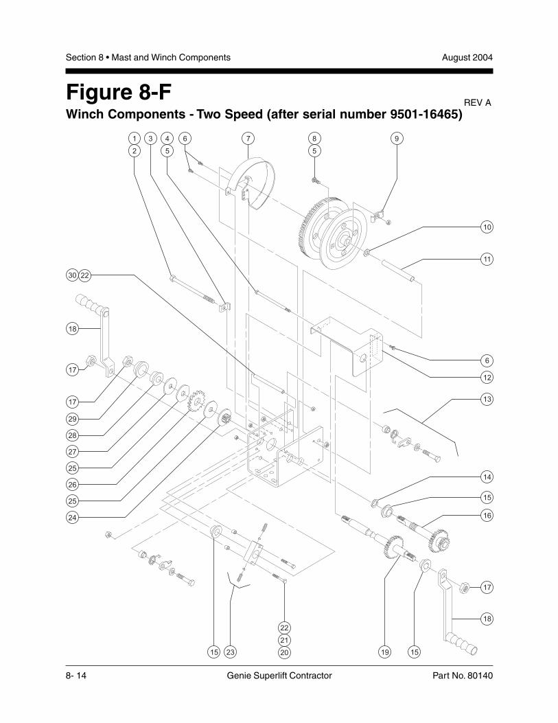
August 2004Section 8 • Mast and Winch Components
8- 14 Genie Superlift Contractor Part No. 80140
Figure 8-FWinch Components - Two Speed (after serial number 9501-16465)
28
1915 15
3 76 91
2
4
5
8
5
18
17
2230
17
24
25
26
25
27
29
10
11
18
17
16
14
15
12
6
20
21
22
23
13
REV A

Section 8 • Mast and Winch ComponentsAugust 2004
Part No. 80140 Genie Superlift Contractor 8- 15
FIGURE 8-F
Item Part No. Description Qty.
— 32946 Two Speed Winch Assembly withDecals (after serial number9501-16465)
— 40130 Cable Keeper Kit (includes itemnumbers 5, 8 and 9)
1 78037 Screw - HHC, 3/8 -16 x 5.5 inches
2 4828 Nylock Nut, 3/8 -16
3 80145 Reel Lock Bolt .............................. 1
4 80146 Screw - HHC, 1/4 -20 x 5.25 inches
5 6091 Nylock Nut, 1/4 -20
6 80147 Screw - FHC, Threaded, 0.5 inch
7 80148 Reel Cover .................................... 1
8 80149 Carriage Bolt, 1/4 -20 x 0.5 inch
9 37065 Cable Keeper ................................ 1
10 80150 Flat Washer, 1/2 inch
11 40113 Reel Spacer .................................. 1
12 80151 Gear Cover ................................... 1
13 40117 Ratchet Pawl Kit ........................... 1— 8516 Screw - HHC,
3/8 -16 x 1.5 inches, GR 5— 5397 Flat Washer, 5/16 inch— 80154 Ratchet Pawl— 80153 Ratchet Spring— 80152 Ratchet Spacer— 4828 Nylock Nut, 3/8 -16
14 40116 Retaining Ring, 0.75 inch ............. 1
15 40126 Sintered Iron Bearing, 0.75 inch ... 3
16 80155 Pinion Shaft Assembly ................. 1
17 38028 Low Profile Nylock Nut, 5/8 -11
18 40125 Handle, 8 inches ........................... 2
19 72264 Input Shaft Assembly ................... 1
20 6145 Screw - HHC,1/4 -20 x 1.5 inches, GR 5
21 40115 Brake Spring Spacer .................... 2
22 6889 Low Profile Nylock Nut, 1/4 -20
Item Part No. Description Qty.
23 40127 Detent Block Assembly ................ 1— 40509 Detent Spring ................................ 2— 40510 Detent Ball .................................... 2— 80156 Detent Block ................................. 1
24 80157 Pinion Gear ................................... 1
25 37061 Disc Break .................................... 2
26 37062 Ratchet Gear ................................ 1
27 40122 Pinion Plate .................................. 1
28 40123 Brake Spacer ................................ 1
29 37064 Sintered Iron Bearing1.25 inches ................................... 1
30 40128 Base Spacer ................................. 1
REV A
August 2004Section 8 • Mast and Winch Components
8- 16 Genie Superlift Contractor Part No. 80140
This page intentionally left blank.

Section 9 • Load Handling AttachmentsAugust 2004
Part No. 80140 Genie Superlift Contractor 9- 1
LoadLoadLoadLoadLoadHandlingHandlingHandlingHandlingHandling
AttachmentsAttachmentsAttachmentsAttachmentsAttachments
Section Nine

August 2004Section 9 • Load Handling Attachments
9- 2 Genie Superlift Contractor Part No. 80140
Figure 9-AForks
3 1 421
7
2
5
6
6
5

Section 9 • Load Handling AttachmentsAugust 2004
Part No. 80140 Genie Superlift Contractor 9- 3
FIGURE 9-A
Item Part No. Description Qty.
— 33543-S Adjustable Fork Assembly(includes items 1 - 4)
1 33707-S Adjustable Fork ............................ 2
2 48301 Toggle Pin, 0.5 x 8.13 inches ....... 2
3 35821 Adjustable Carrier Assembly ....... 1
4 33674 Snap Pin, 0.375 x 0.25 inch ......... 2
5 80679 Ball Retaining Pin,0.5 x 2.5 inches ............................ 2
6 33366-S Fork Extension ............................. 2
7 33984 Standard Fork Assembly .............. 1

August 2004Section 9 • Load Handling Attachments
9- 4 Genie Superlift Contractor Part No. 80140
Figure 9-BPipe Cradle, Load Platform and Boom Arm
6 5
31
2
7
8
4

Section 9 • Load Handling AttachmentsAugust 2004
Part No. 80140 Genie Superlift Contractor 9- 5
FIGURE 9-B
Item Part No. Description Qty.
1 8170 Wing Nut, 1/4 -20 ........................... 8
2 33045 U-bolt,1/4 -20 x 1.5 x 3.75 x 1.25 inches .. 4
3 80597 Pipe Cradle .................................. 2
4 35021 Load Platform Assembly .............. 1
5 32579-S Clevis Boom ................................. 1
6 80679 Ball Retaining Pin,0.5 x 2.5 inches ............................ 1
7 38696 Toggle Pin, 0.5 x 7.75 inches ....... 1
8 32567-S Boom Arm Assembly(includes items 5, 6 and 7) ........... 1

August 2004Section 9 • Load Handling Attachments
9- 6 Genie Superlift Contractor Part No. 80140
Figure 9-CRear Wheels

Section 9 • Load Handling AttachmentsAugust 2004
Part No. 80140 Genie Superlift Contractor 9- 7
FIGURE 9-C
Item Part No. Description Qty.
— 35848-S Rear Wheel Accessory -Complete
1 33831-S Wheel Spacer Weldment ............. 1
2 35064 Rear Wheel, 10 x 2.75 inches ...... 2
3 33830-S Rear Spacer Mount Weldment,Right Side ..................................... 1
4 6094 Cotter Pin ..................................... 2
5 57237 Transport Wheels Axle Rod ......... 1
6 6564 Shim Washer,0.75 x 1.125 x 0.093 inch
7 33829-S Rear Spacer Mount Weldment,Left Side ....................................... 1
8 6019 Screw - HHC,3/8 - 16 x 1.125 inches, GR 5
9 4828 Nylock Nut, 3/8 - 16

August 2004Section 9 • Load Handling Attachments
9- 8 Genie Superlift Contractor Part No. 80140
This page intentionally left blank.

Pa
rts an
d Se
rvice M
an
ua
l Su
pe
rlift Co
ntra
cto
rP
art N
o. 8
01
40

Genie North AmericaPhone 425.881.1800
Toll Free USA and Canada
800.536.1800
Fax 425.883.3475
Genie Australia Pty Ltd.Phone +61 7 3375 1660
Fax +61 7 3375 1002
Genie ChinaPhone +86 21 53852570
Fax +86 21 53852569
Genie MalaysiaPhone +65 98 480 775
Fax +65 67 533 544
Genie JapanPhone +81 3 3453 6082
Fax +81 3 3453 6083
Genie KoreaPhone +82 25 587 267
Fax +82 25 583 910
Genie BrasilPhone +55 11 41 665 755
Fax +55 11 41 665 754
Genie HollandPhone +31 10 220 7911
Fax +31 10 220 6642
Genie ScandinaviaPhone +46 31 3409612
Fax +46 31 3409613
Genie FrancePhone +33 (0)2 37 26 09 99
Fax +33 (0)2 37 26 09 98
Genie IbericaPhone +34 93 579 5042
Fax +34 93 579 5059
Genie GermanyPhone +49 (0)4202 88520
Fax +49 (0)4202 8852-20
Genie U.K.Phone +44 (0)1476 584333
Fax +44 (0)1476 584334
Genie Mexico CityPhone +52 55 5666 5242
Fax +52 55 5666 3241 Dis
trib
ute
d B
y: