INSTALLATION AND ASSEMBLY INSTRUCTIONS TSFL | TMFL …
4
1. Turn off electrical supply at the breaker. 2. Follow all local electrical codes for wiring and grounding requirements. 3. Check to make sure that the supply voltage to the fixture is compatible with the fixture driver. 4. Connect the white fixture wire with white service wire. 5. Connect the black fixture wire to the black service wire. 6. Connect the green fixture wire to the ground wire. 7. Make sure all connections are secure using approved connecting devices. WIRING KNUCKLE MOUNTING (PFS SERIES & PFM SERIES) MOUNTING - For floodlights supplied with a threaded knuckle mount to any metal 1/2" NPT mounting hole. Do not recess fixture. AIMING - To adjust vertically, loosen aiming screw and tilt fixture in desired position. To adjust horizontally loosen swivel screw and locknut. Aim as needed. Tighten swivel screw and locknut. NOTE: Fixtures are not designed to be mounted upside down. SLIPFITTER MOUNTING (PFL SERIES & PFXL SERIES) MOUNTING - For floodlights supplied with a slipfitter, mount slipfitter over tenon (after wiring process). Securely tighten two set screws. Slipfitter is designed to fit over 2 3/8" tenon or pipe. AIMING - Remove side adjustment panel by removing locking screws. Loosen adjustment bolt and adjust the fixture to the desired position. Tighten adjustment bolt. Replace side adjustment panel and replace screws. NOTE: Fixtures are not designed to be mounted upside down. MOUNTING - For floodlights supplied with a trunion mount to any surface, with 5/16" bolts you provide. Make sure the fixture is securely fastened. AIMING - Remove small position-lock screw. Loosen adjustment bolt and adjust the fixture to the desired position. Tighten adjustment bolts securely (10ft/lbs). Reinsert small position lock screw. NOTE: Fixtures are not designed to be mounted upside down. TRUNION MOUNTING (PFL SERIES & PFXL SERIES) NOTE: Optional 0-10 V Dimming. Dimming provided through grey & purple wires. Refer to control manufacturer for wiring instructions. IMPORTANT: READ BEFORE REMOVING FIXTURE FROM CARTON. RETAIN FOR FUTURE REFERENCE SAFETY: This fixture must be wired in accordance with the NATIONAL ELECTRICAL CODE and applicable local codes and ordinances. A person familiar with the construction and operation of the product and the hazards involved must install this product. A qualified licensed electrician should complete all work. Proper grounding is required for safety. WARNING: Make certain power is OFF before installing or maintaining fixture. RISK OF INJURY: Fixture may become damaged and/or unstable if not installed properly. 240-144LSI Rev. 05/17 ©2017 LSI Industries Inc. Installation Questions? Call LSI Field Service Department at: 1-800-436-7800 Ext. 3300 Fax: 1-877-861-1368 TSFL | TMFL | TLFL Series INSTALLATION AND ASSEMBLY INSTRUCTIONS
Transcript of INSTALLATION AND ASSEMBLY INSTRUCTIONS TSFL | TMFL …
1. Turn off electrical supply at the breaker. 2. Follow all local electrical codes for wiring and grounding requirements. 3. Check to make sure that the supply voltage to the fixture is compatible with the fixture driver. 4. Connect the white fixture wire with white service wire. 5. Connect the black fixture wire to the black service wire. 6. Connect the green fixture wire to the ground wire. 7. Make sure all connections are secure using approved connecting devices.
WIRING
KNUCKLE MOUNTING (PFS SERIES & PFM SERIES)MOUNTING - For floodlights supplied with a threaded knuckle mount to any metal 1/2" NPT mounting hole. Do not recess fixture.AIMING - To adjust vertically, loosen aiming screw and tilt fixture in desired position. To adjust horizontally loosen swivel screw and locknut. Aim as needed. Tighten swivel screw and locknut. NOTE: Fixtures are not designed to be mounted upside down.
SLIPFITTER MOUNTING (PFL SERIES & PFXL SERIES)MOUNTING - For floodlights supplied with a slipfitter, mount slipfitter over tenon (after wiring process). Securely tighten two set screws. Slipfitter is designed to fit over 2 3/8" tenon or pipe. AIMING - Remove side adjustment panel by removing locking screws. Loosen adjustment bolt and adjust the fixture to the desired position. Tighten adjustment bolt. Replace side adjustment panel and replace screws. NOTE: Fixtures are not designed to be mounted upside down.
MOUNTING - For floodlights supplied with a trunion mount to any surface, with 5/16" bolts you provide. Make sure the fixture is securely fastened.AIMING - Remove small position-lock screw. Loosen adjustment bolt and adjust the fixture to the desired position. Tighten adjustment bolts securely (10ft/lbs). Reinsert small position lock screw.NOTE: Fixtures are not designed to be mounted upside down.
TRUNION MOUNTING (PFL SERIES & PFXL SERIES)
NOTE: Optional 0-10 V Dimming. Dimming provided through grey & purple wires. Refer to control manufacturer for wiring instructions.
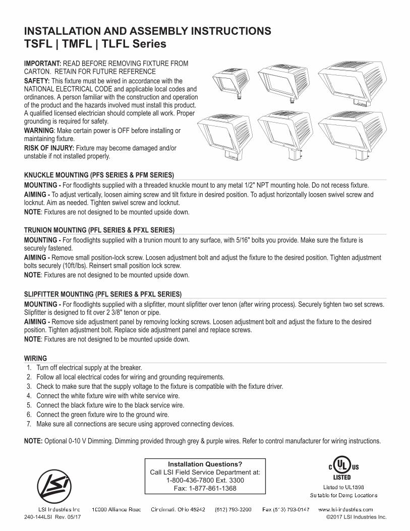
IMPORTANT: READ BEFORE REMOVING FIXTURE FROM CARTON. RETAIN FOR FUTURE REFERENCESAFETY: This fixture must be wired in accordance with the NATIONAL ELECTRICAL CODE and applicable local codes and ordinances. A person familiar with the construction and operation of the product and the hazards involved must install this product. A qualified licensed electrician should complete all work. Proper grounding is required for safety.WARNING: Make certain power is OFF before installing or maintaining fixture. RISK OF INJURY: Fixture may become damaged and/or unstable if not installed properly.
240-144LSI Rev. 05/17 ©2017 LSI Industries Inc.
Installation Questions?Call LSI Field Service Department at:
1-800-436-7800 Ext. 3300Fax: 1-877-861-1368
TSFL | TMFL | TLFL SeriesINSTALLATION AND ASSEMBLY INSTRUCTIONS
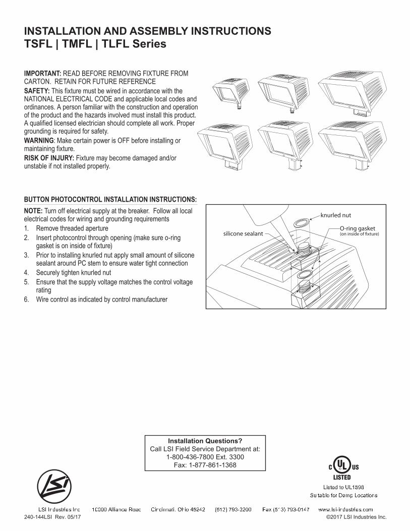
BUTTON PHOTOCONTROL INSTALLATION INSTRUCTIONS:NOTE: Turn off electrical supply at the breaker. Follow all local electrical codes for wiring and grounding requirements1. Remove threaded aperture2. Insert photocontrol through opening (make sure o-ring gasket is on inside of fixture)3. Prior to installing knurled nut apply small amount of silicone sealant around PC stem to ensure water tight connection4. Securely tighten knurled nut5. Ensure that the supply voltage matches the control voltage rating6. Wire control as indicated by control manufacturer
O-ring gasket(on inside of �xture)
knurled nut
silicone sealant
IMPORTANT: READ BEFORE REMOVING FIXTURE FROM CARTON. RETAIN FOR FUTURE REFERENCESAFETY: This fixture must be wired in accordance with the NATIONAL ELECTRICAL CODE and applicable local codes and ordinances. A person familiar with the construction and operation of the product and the hazards involved must install this product. A qualified licensed electrician should complete all work. Proper grounding is required for safety.WARNING: Make certain power is OFF before installing or maintaining fixture. RISK OF INJURY: Fixture may become damaged and/or unstable if not installed properly.
240-144LSI Rev. 05/17 ©2017 LSI Industries Inc.
Installation Questions?Call LSI Field Service Department at:
1-800-436-7800 Ext. 3300Fax: 1-877-861-1368
TSFL | TMFL | TLFL SeriesINSTALLATION AND ASSEMBLY INSTRUCTIONS
MONTAJE DE NUDILLO (SERIE PFS & SERIE PFM)MONTAJE - Para los focos que vienen con un empalme a rosca móntelos en cualquier agujero de montaje metálico NPT de 1/2". El dispositivo no debe de estar en un hueco.PUNTERÍA - Para ajustarlo verticalmente, afloje el tornillo de alzada y mueva el aplique en la posición deseada. Para ajustarhorizontalmente afloje el tornillo de pivote y la tuerca de bloqueo. Oriéntelo según necesite. Ajuste el tornillo de pivote y la tuerca de bloqueo. NOTA: Los apliques no están diseñados para colgarse boca abajo.
1. Apague el suministro eléctrico en la caja del interruptor.2. Consulte los códigos eléctricos locales para ver los requisitos de cableado y puesta a tierra.3. Revise para estar seguro que el voltaje de suministro al dispositivo sea compatible con la reactancia del dispositivo (120-277V).4. Conecte el cable blanco del dispositivo al cable blanco de servicio.5. Conecte el cable negro del dispositivo al cable negro de servicio.6. Conecte el cable verde del dispositivo al cable de puesta a tierra.7. Asegúrese que todas las conexiones estén seguras usando los dispositivos aprobados de conexión.8. Prenda el suministro eléctrico en la caja del interruptor
CABLEADO
MONTAJE DE SLIPFITTER (SERIE PFL & SERIE PFXL)MONTAJE - Para focos dotados de ajuste deslizable, coloque el ajuste deslizable sobre la espiga (luego del proceso de cableado). Ajuste firmemente dos tornillos de fijación. El ajuste deslizable está diseñado para entrar en espigas o caños de 2 3/8". PUNTERÍA - Retire el panel de ajuste lateral quitando los tornillos de fijación. Afloje el tornillo de ajuste y ajuste el aplique a la posición deseada. Ajuste el tornillo de ajuste. Vuelva a colocar el panel de ajuste lateral y coloque nuevamente los tornillos.NOTE: Los apliques no están diseñados para colgarse boca abajo.
MONTAJE - Para los focos que vienen con muñón móntelos en cualquier superficie con tornillos de 5/16" (no incluidos). Asegúrese de ajustar bien el aplique.PUNTERÍA - Retire el tornillo pequeño de bloqueo de posición. Afloje el tornillo de ajuste y ajuste el aplique a la posición deseada. Ajuste el tornillo de ajuste firmemente (10 pies/libra). Vuelva a colocar el tornillo pequeño de bloqueo de posición. NOTE: Los apliques no están diseñados para colgarse boca abajo.
MONTAJE DE MUÑÓN (SERIE PFL & SERIE PFXL)
NOTA: Opcional 0-10 voltios de atenuación. Oscurecimiento proporcionada a través de los cables gris y púrpura. Consulte el fabricante para controlar las instrucciones de cableado.
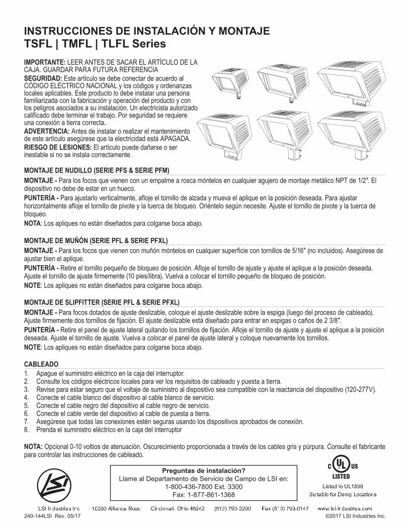
IMPORTANTE: LEER ANTES DE SACAR EL ARTÍCULO DE LA CAJA. GUARDAR PARA FUTURA REFERENCIASEGURIDAD: Este artículo se debe conectar de acuerdo al CÓDIGO ELÉCTRICO NACIONAL y los códigos y ordenanzas locales aplicables. Este producto lo debe instalar una persona familiarizada con la fabricación y operación del producto y con los peligros asociados a su instalación. Un electricista autorizado calificado debe terminar el trabajo. Por seguridad se requiere una conexión a tierra correcta.ADVERTENCIA: Antes de instalar o realizar el mantenimiento de este artículo asegúrese que la electricidad está APAGADA.RIESGO DE LESIONES: El artículo puede dañarse o ser inestable si no se instala correctamente.
TSFL | TMFL | TLFL SeriesINSTRUCCIONES DE INSTALACIÓN Y MONTAJE
Preguntas de instalación?Llame al Departamento de Servicio de Campo de LSI en:
1-800-436-7800 Ext. 3300Fax: 1-877-861-1368
240-144LSI Rev. 05/17 ©2017 LSI Industries Inc.
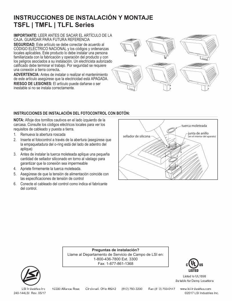
INSTRUCCIONES DE INSTALACIÓN DEL FOTOCONTROL CON BOTÓN:NOTA: Afloje dos tornillos cautivos en el lado izquierdo de la carcasa. Consulte los códigos eléctricos locales para ver los requisitos de cableado y puesta a tierra.1. Remueva la abertura roscada2. Inserte el fotocontrol a través de la abertura (asegúrese que la empaquetadura del o-ring está del lado de adentro del aplique)3. Antes de instalar la tuerca moleteada aplique una pequeña cantidad de sellador siliconado en torno al vástago para garantizar que la conexión sea impermeable4. Apriete firmemente la tuerca moleteada.5. Asegúrese de que la tensión de alimentación coincide con las especificaciones de tensión de control6. Conecte el cableado del control como indica el fabricante del control.
junta de anillo(en el interior del aparato)
tuerca moleteada
sellador de silicona
IMPORTANTE: LEER ANTES DE SACAR EL ARTÍCULO DE LA CAJA. GUARDAR PARA FUTURA REFERENCIASEGURIDAD: Este artículo se debe conectar de acuerdo al CÓDIGO ELÉCTRICO NACIONAL y los códigos y ordenanzas locales aplicables. Este producto lo debe instalar una persona familiarizada con la fabricación y operación del producto y con los peligros asociados a su instalación. Un electricista autorizado calificado debe terminar el trabajo. Por seguridad se requiere una conexión a tierra correcta.ADVERTENCIA: Antes de instalar o realizar el mantenimiento de este artículo asegúrese que la electricidad está APAGADA.RIESGO DE LESIONES: El artículo puede dañarse o ser inestable si no se instala correctamente.
TSFL | TMFL | TLFL SeriesINSTRUCCIONES DE INSTALACIÓN Y MONTAJE
Preguntas de instalación?Llame al Departamento de Servicio de Campo de LSI en:
1-800-436-7800 Ext. 3300Fax: 1-877-861-1368
240-144LSI Rev. 05/17 ©2017 LSI Industries Inc.