I. BASIC INFORMATION COMMERCIAL BUILDING (HYPERMARKET...
91
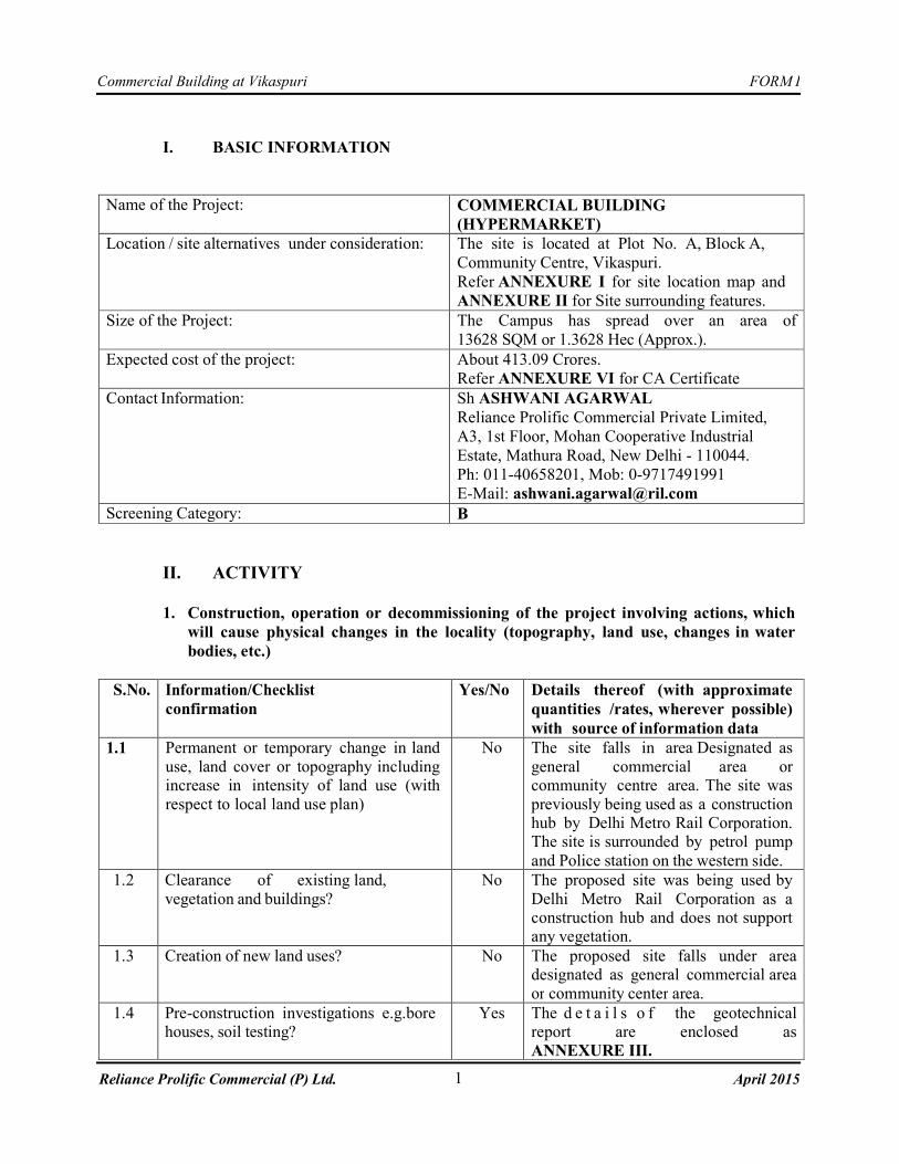
FORM I 1 Commercial Building at Vikaspuri April 2015 Reliance Prolific Commercial (P) Ltd. I. BASIC INFORMATION Name of the Project: COMMERCIAL BUILDING (HYPERMARKET) Location / site alternatives under consideration: The site is located at Plot No. A, Block A, Community Centre, Vikaspuri. Refer ANNEXURE I for site location map and ANNEXURE II for Site surrounding features. Size of the Project: The Campus has spread over an area of 13628 SQM or 1.3628 Hec (Approx.). Expected cost of the project: About 413.09 Crores. Refer ANNEXURE VI for CA Certificate Contact Information: Sh ASHWANI AGARWAL Reliance Prolific Commercial Private Limited, A3, 1st Floor, Mohan Cooperative Industrial Estate, Mathura Road, New Delhi - 110044. Ph: 011-40658201, Mob: 0-9717491991 E-Mail: [email protected] Screening Category: B II. ACTIVITY 1. Construction, operation or decommissioning of the project involving actions, which will cause physical changes in the locality (topography, land use, changes in water bodies, etc.) S.No. Information/Checklist confirmation Yes/No Details thereof (with approximate quantities /rates, wherever possible) with source of information data 1.1 Permanent or temporary change in land use, land cover or topography including increase in intensity of land use (with respect to local land use plan) No The site falls in area Designated as general commercial area or community centre area. The site was previously being used as a construction hub by Delhi Metro Rail Corporation. The site is surrounded by petrol pump and Police station on the western side. 1.2 Clearance of existing land, vegetation and buildings? No The proposed site was being used by Delhi Metro Rail Corporation as a construction hub and does not support any vegetation. 1.3 Creation of new land uses? No The proposed site falls under area designated as general commercial area or community center area. 1.4 Pre-construction investigations e.g.bore houses, soil testing? Yes The details of the geotechnical report are enclosed as ANNEXURE III.
Transcript of I. BASIC INFORMATION COMMERCIAL BUILDING (HYPERMARKET...
FORM I
1
Commercial Building at Vikaspuri
April 2015 Reliance Prolific Commercial (P) Ltd.
I. BASIC INFORMATION
Name of the Project: COMMERCIAL BUILDING
(HYPERMARKET)
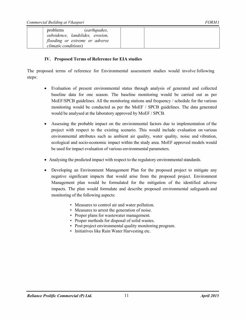
Location / site alternatives under consideration: The site is located at Plot No. A, Block A,
Community Centre, Vikaspuri.
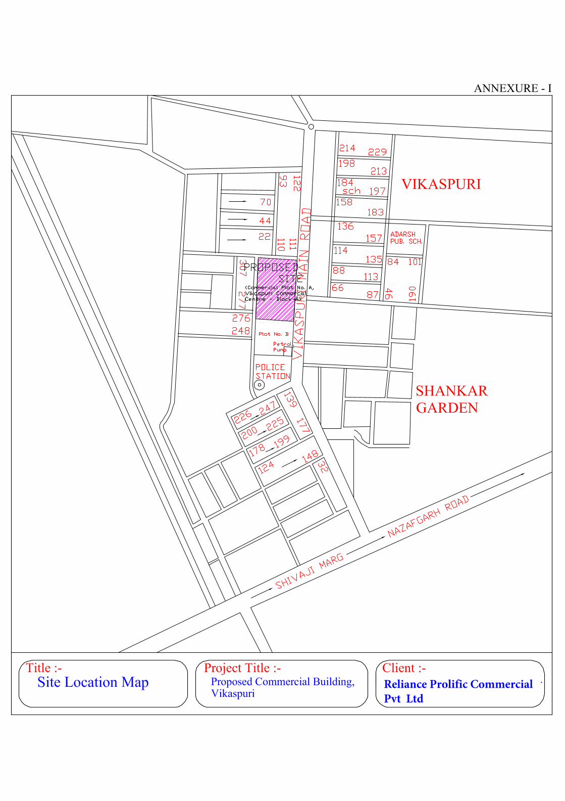
Refer ANNEXURE I for site location map and
ANNEXURE II for Site surrounding features.
Size of the Project: The Campus has spread over an area of
13628 SQM or 1.3628 Hec (Approx.).
Expected cost of the project: About 413.09 Crores.
Refer ANNEXURE VI for CA Certificate
Contact Information: Sh ASHWANI AGARWAL
Reliance Prolific Commercial Private Limited,
A3, 1st Floor, Mohan Cooperative Industrial
Estate, Mathura Road, New Delhi - 110044.
Ph: 011-40658201, Mob: 0-9717491991
E-Mail: [email protected]
Screening Category: B
II. ACTIVITY
1. Construction, operation or decommissioning of the project involving actions, which
will cause physical changes in the locality (topography, land use, changes in water
bodies, etc.)
S.No. Information/Checklist
confirmation
Yes/No Details thereof (with approximate
quantities /rates, wherever possible)
with source of information data
1.1 Permanent or temporary change in land
use, land cover or topography including increase in intensity of land use (with
respect to local land use plan)
No The site falls in area Designated as
general commercial area or community centre area. The site was
previously being used as a construction hub by Delhi Metro Rail Corporation. The site is surrounded by petrol pump
and Police station on the western side.
1.2 Clearance of existing land,
vegetation and buildings?
No The proposed site was being used by
Delhi Metro Rail Corporation as a construction hub and does not support any vegetation.
1.3 Creation of new land uses? No The proposed site falls under area designated as general commercial area
or community center area.
1.4 Pre-construction investigations e.g.bore houses, soil testing?
Yes The d e t a i l s o f the geotechnical report are enclosed as
ANNEXURE III.
FORM I
2
Commercial Building at Vikaspuri
April 2015 Reliance Prolific Commercial (P) Ltd.
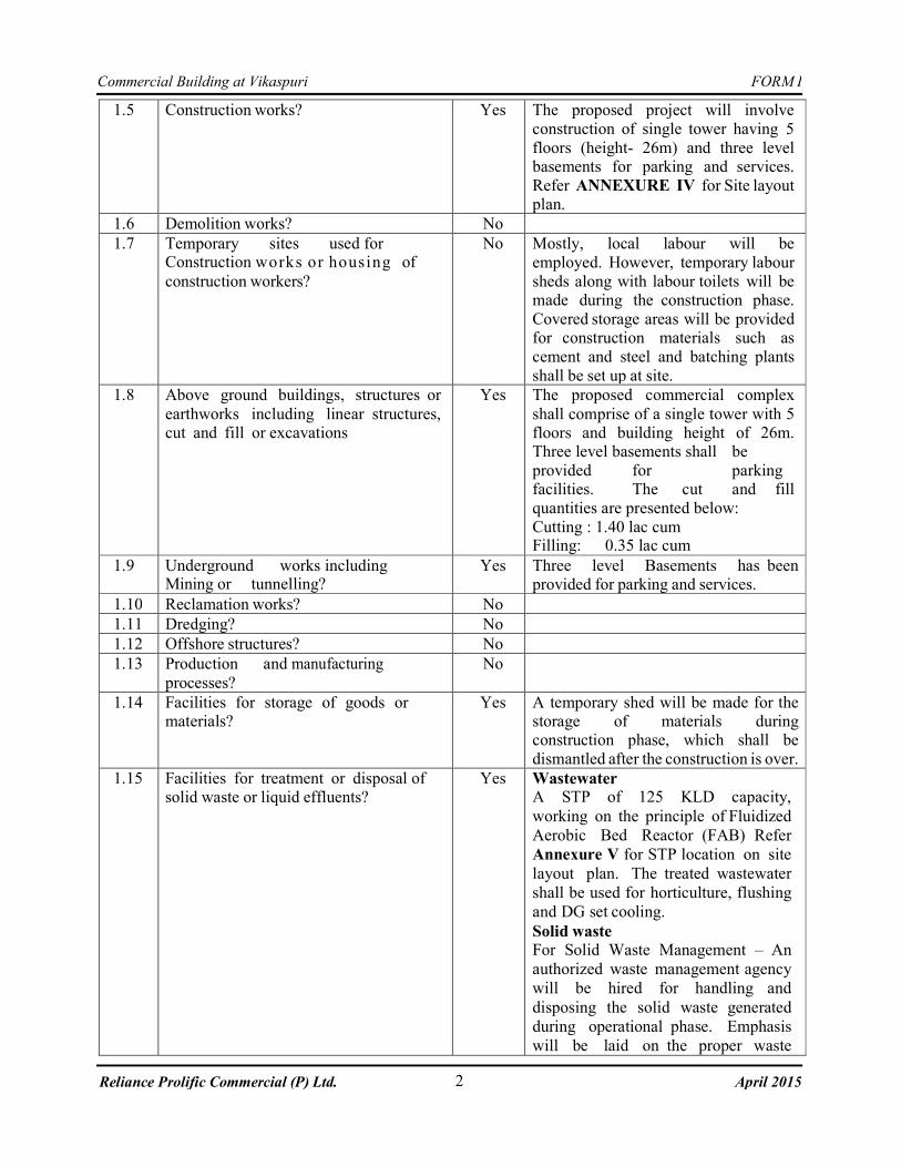
1.5 Construction works? Yes The proposed project will involve
construction of single tower having 5
floors (height- 26m) and three level basements for parking and services.
Refer ANNEXURE IV for Site layout plan.
1.6 Demolition works? No
1.7 Temporary sites used for Construction works or housing of
construction workers?
No Mostly, local labour will be
employed. However, temporary labour
sheds along with labour toilets will be made during the construction phase.
Covered storage areas will be provided for construction materials such as
cement and steel and batching plants
shall be set up at site.
1.8 Above ground buildings, structures or
earthworks including linear structures, cut and fill or excavations
Yes The proposed commercial complex
shall comprise of a single tower with 5 floors and building height of 26m. Three level basements shall be
provided for parking facilities. The cut and fill
quantities are presented below:
Cutting : 1.40 lac cum Filling: 0.35 lac cum
1.9 Underground works including Mining or tunnelling?
Yes Three level Basements has been provided for parking and services.
1.10 Reclamation works? No
1.11 Dredging? No
1.12 Offshore structures? No
1.13 Production and manufacturing
processes?
No
1.14 Facilities for storage of goods or materials?
Yes A temporary shed will be made for the storage of materials during construction phase, which shall be
dismantled after the construction is over.
1.15 Facilities for treatment or disposal of solid waste or liquid effluents?
Yes Wastewater A STP of 125 KLD capacity,
working on the principle of Fluidized
Aerobic Bed Reactor (FAB) Refer
Annexure V for STP location on site
layout plan. The treated wastewater
shall be used for horticulture, flushing
and DG set cooling.
Solid waste For Solid Waste Management – An
authorized waste management agency
will be hired for handling and
disposing the solid waste generated
during operational phase. Emphasis
will be laid on the proper waste
FORM I
3
Commercial Building at Vikaspuri
April 2015 Reliance Prolific Commercial (P) Ltd.
segregation into Biodegradable, Non-
biodegradable, Recyclable and Inert
wastes.
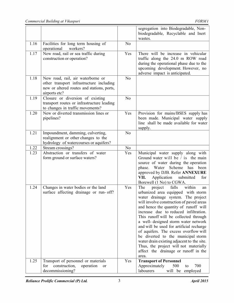
1.16 Facilities for long term housing of
operational workers?
No
1.17 New road, rail or sea traffic during construction or operation?
Yes There will be increase in vehicular traffic along the 24.0 m ROW road
during the operational phase due to the upcoming development. However, no adverse impact is anticipated.
1.18 New road, rail, air waterborne or other transport infrastructure including
new or altered routes and stations, ports,
airports etc?
No
1.19 Closure or diversion of existing transport routes or infrastructure leading
to changes in traffic movements?
No
1.20 New or diverted transmission lines or pipelines?
Yes Provision for mains/BSES supply has been made. Municipal water supply
line shall be made available for water supply.
1.21 Impoundment, damming, culverting,
realignment or other changes to the
hydrology of watercourses or aquifers?
No
1.22 Stream crossings? No
1.23 Abstraction or transfers of water form ground or surface waters?
Yes Municipal water supply along with
Ground water will be / is the main source of water during the operation
phase. Water Scheme has been approved by DJB. Refer ANNEXURE VII. Application submitted for
Borewell (1 No) to CGWA.
1.24 Changes in water bodies or the land surface affecting drainage or run- off?
Yes The project falls within an
urbanized area equipped with storm water drainage system. The project will involve construction of paved areas
and hence the quantity of runoff will
increase due to reduced infiltration. This runoff will be collected through
a well- designed storm water network and will be used for artificial recharge of aquifers. The excess overflow will
be diverted to the municipal storm water drain existing adjacent to the site. Thus, the project will not materially
affect the drainage or runoff in the area.
1.25 Transport of personnel or materials for construction, operation or
decommissioning?
Yes Transport of Personnel Approximately 500 to 700
labourers will be employed
FORM I
4
Commercial Building at Vikaspuri
April 2015 Reliance Prolific Commercial (P) Ltd.
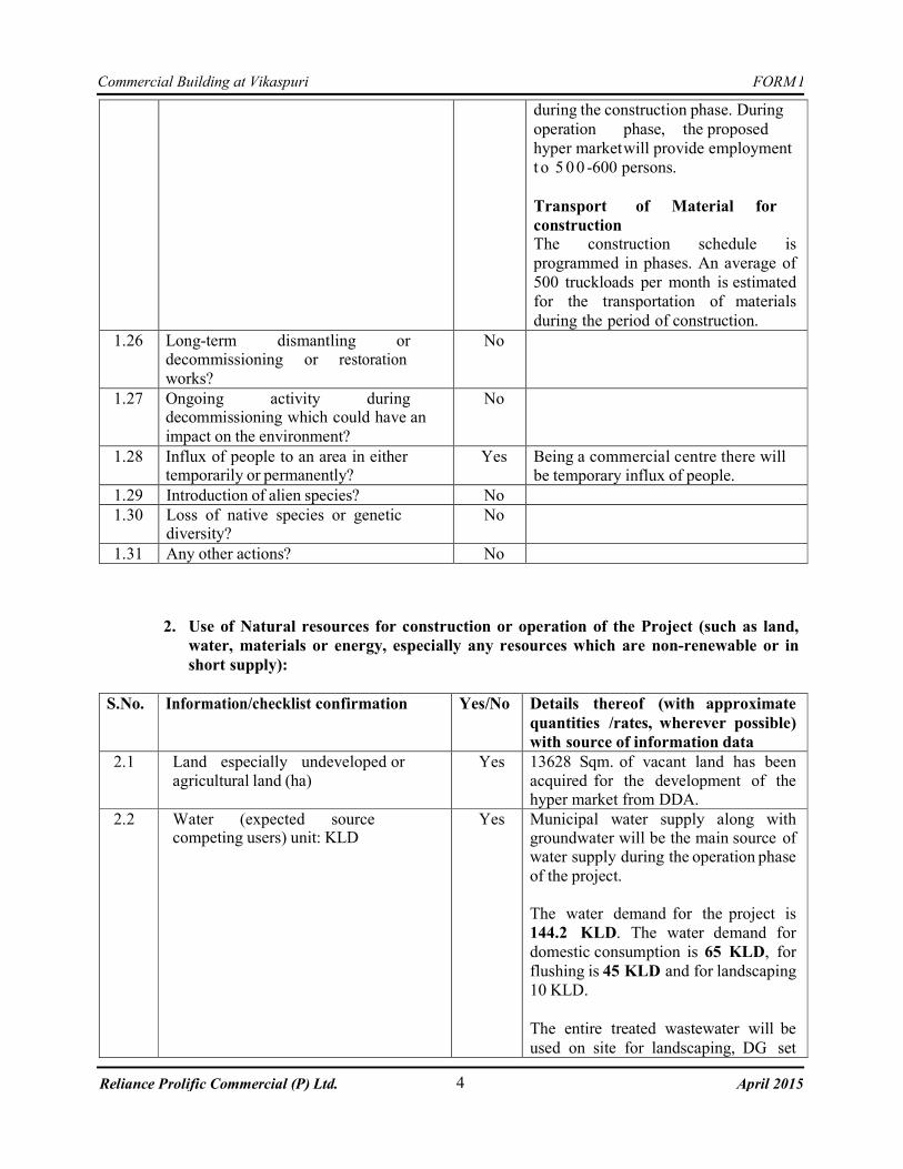
during the construction phase. During
operation phase, the proposed
hyper market will provide employment
t o 5 00 -600 persons.
Transport of Material for
construction The construction schedule is
programmed in phases. An average of
500 truckloads per month is estimated
for the transportation of materials
during the period of construction.
1.26 Long-term dismantling or decommissioning or restoration
works?
No
1.27 Ongoing activity during decommissioning which could have an
impact on the environment?
No
1.28 Influx of people to an area in either temporarily or permanently?
Yes Being a commercial centre there will
be temporary influx of people.
1.29 Introduction of alien species? No
1.30 Loss of native species or genetic diversity?
No
1.31 Any other actions? No
2. Use of Natural resources for construction or operation of the Project (such as land,
water, materials or energy, especially any resources which are non-renewable or in
short supply):
S.No. Information/checklist confirmation Yes/No Details thereof (with approximate
quantities /rates, wherever possible)
with source of information data
2.1 Land especially undeveloped or
agricultural land (ha)
Yes 13628 Sqm. of vacant land has been
acquired for the development of the hyper market from DDA.
2.2 Water (expected source competing users) unit: KLD
Yes Municipal water supply along with groundwater will be the main source of water supply during the operation phase
of the project.
The water demand for the project is
144.2 KLD. The water demand for
domestic consumption is 65 KLD, for
flushing is 45 KLD and for landscaping
10 KLD.
The entire treated wastewater will be
used on site for landscaping, DG set
FORM I
5
Commercial Building at Vikaspuri
April 2015 Reliance Prolific Commercial (P) Ltd.
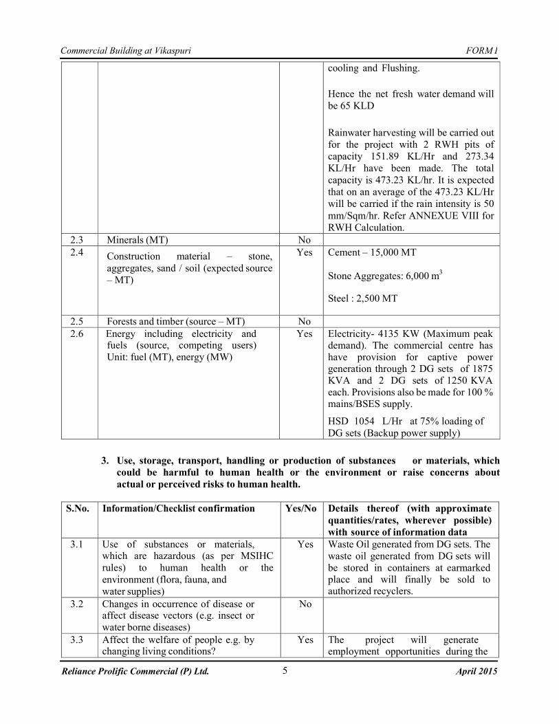
cooling and Flushing.
Hence the net fresh water demand will
be 65 KLD
Rainwater harvesting will be carried out
for the project with 2 RWH pits of
capacity 151.89 KL/Hr and 273.34
KL/Hr have been made. The total
capacity is 473.23 KL/hr. It is expected
that on an average of the 473.23 KL/Hr
will be carried if the rain intensity is 50
mm/Sqm/hr. Refer ANNEXUE VIII for
RWH Calculation.
2.3 Minerals (MT) No
2.4 Construction material – stone,
aggregates, sand / soil (expected source
– MT)
Yes Cement – 15,000 MT
Stone Aggregates: 6,000 m3
Steel : 2,500 MT
2.5 Forests and timber (source – MT) No
2.6 Energy including electricity and fuels (source, competing users)
Unit: fuel (MT), energy (MW)
Yes Electricity- 4135 KW (Maximum peak demand). The commercial centre has
have provision for captive power generation through 2 DG sets of 1875
KVA and 2 DG sets of 1250 KVA
each. Provisions also be made for 100 % mains/BSES supply. HSD 1054 L/Hr at 75% loading of
DG sets (Backup power supply)
3. Use, storage, transport, handling or production of substances or materials, which
could be harmful to human health or the environment or raise concerns about
actual or perceived risks to human health.
S.No. Information/Checklist confirmation Yes/No Details thereof (with approximate
quantities/rates, wherever possible)
with source of information data
3.1 Use of substances or materials, which are hazardous (as per MSIHC
rules) to human health or the
environment (flora, fauna, and
water supplies)
Yes Waste Oil generated from DG sets. The
waste oil generated from DG sets will
be stored in containers at earmarked place and will finally be sold to authorized recyclers.
3.2 Changes in occurrence of disease or affect disease vectors (e.g. insect or
water borne diseases)
No
3.3 Affect the welfare of people e.g. by changing living conditions?
Yes The project will generate employment opportunities during the
FORM I
6
Commercial Building at Vikaspuri
April 2015 Reliance Prolific Commercial (P) Ltd.
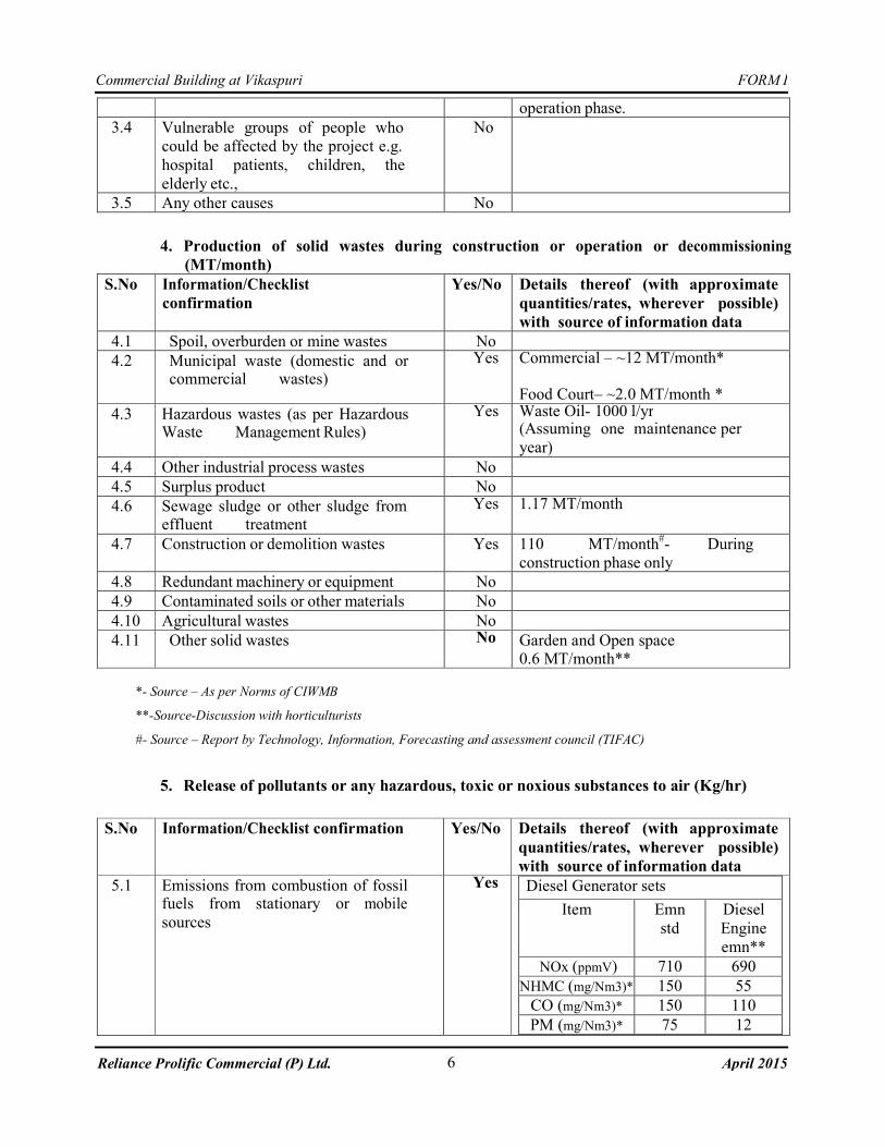
operation phase.
3.4 Vulnerable groups of people who
could be affected by the project e.g.
hospital patients, children, the
elderly etc.,
No
3.5 Any other causes No
4. Production of solid wastes during construction or operation or decommissioning
(MT/month)
S.No Information/Checklist
confirmation
Yes/No Details thereof (with approximate
quantities/rates, wherever possible)
with source of information data
4.1 Spoil, overburden or mine wastes No
4.2 Municipal waste (domestic and or commercial wastes)
Yes Commercial – ~12 MT/month* Food Court– ~2.0 MT/month *
4.3 Hazardous wastes (as per Hazardous Waste Management Rules)
Yes Waste Oil- 1000 l/yr (Assuming one maintenance per
year)
4.4 Other industrial process wastes No
4.5 Surplus product No
4.6 Sewage sludge or other sludge from effluent treatment
Yes 1.17 MT/month
4.7 Construction or demolition wastes Yes 110 MT/month#- During
construction phase only
4.8 Redundant machinery or equipment No
4.9 Contaminated soils or other materials No
4.10 Agricultural wastes No
4.11 Other solid wastes No Garden and Open space 0.6 MT/month**
*- Source – As per Norms of CIWMB
**-Source-Discussion with horticulturists
#- Source – Report by Technology, Information, Forecasting and assessment council (TIFAC)
5. Release of pollutants or any hazardous, toxic or noxious substances to air (Kg/hr)
S.No Information/Checklist confirmation Yes/No Details thereof (with approximate
quantities/rates, wherever possible)
with source of information data
5.1 Emissions from combustion of fossil fuels from stationary or mobile
sources
Yes Diesel Generator sets
Item Emn
std
Diesel
Engine
emn**
NOx (ppmV) 710 690
NHMC (mg/Nm3)* 150 55
CO (mg/Nm3)* 150 110
PM (mg/Nm3)* 75 12
FORM I
7
Commercial Building at Vikaspuri
April 2015 Reliance Prolific Commercial (P) Ltd.
5.2 Emissions from production processes No
5.3 Emissions from materials handling including storage or transport
No
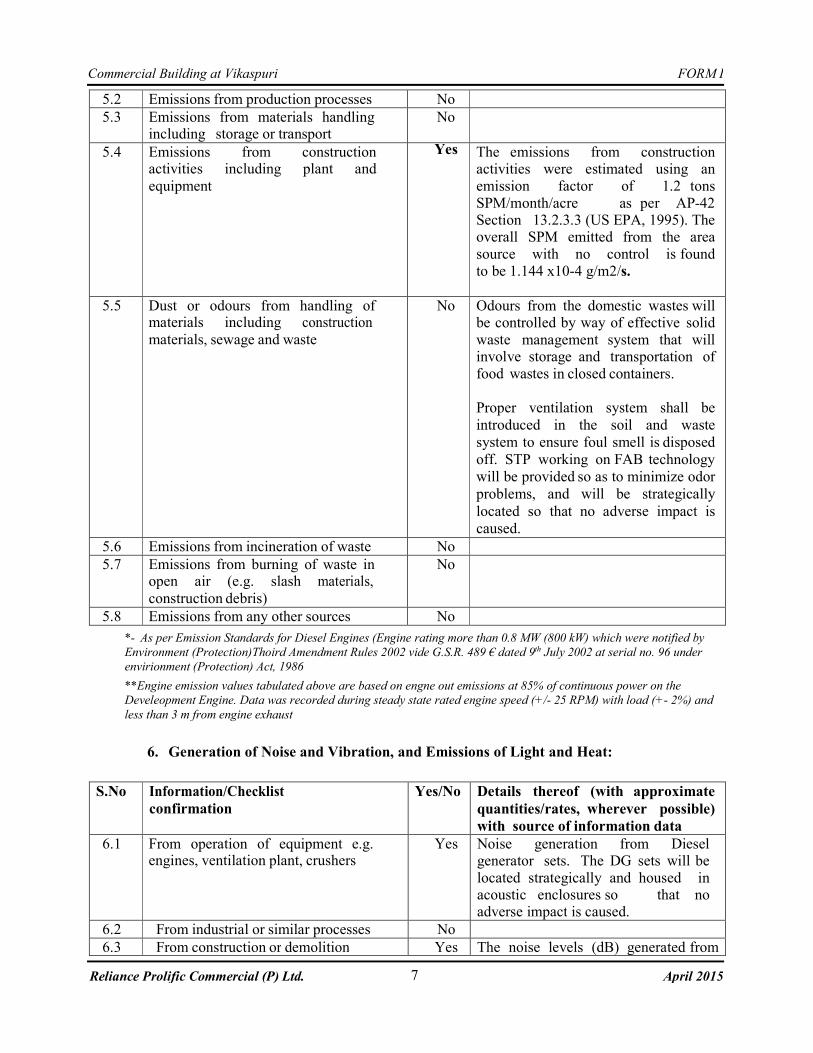
5.4 Emissions from construction activities including plant and
equipment
Yes The emissions from construction activities were estimated using an
emission factor of 1.2 tons
SPM/month/acre as per AP-42 Section 13.2.3.3 (US EPA, 1995). The overall SPM emitted from the area
source with no control is found
to be 1.144 x10⁻⁴ g/m2/s.
5.5 Dust or odours from handling of materials including construction
materials, sewage and waste
No Odours from the domestic wastes will be controlled by way of effective solid
waste management system that will involve storage and transportation of
food wastes in closed containers.
Proper ventilation system shall be
introduced in the soil and waste
system to ensure foul smell is disposed
off. STP working on FAB technology
will be provided so as to minimize odor
problems, and will be strategically
located so that no adverse impact is
caused.
5.6 Emissions from incineration of waste No
5.7 Emissions from burning of waste in open air (e.g. slash materials,
construction debris)
No
5.8 Emissions from any other sources No
*- As per Emission Standards for Diesel Engines (Engine rating more than 0.8 MW (800 kW) which were notified by
Environment (Protection)Thoird Amendment Rules 2002 vide G.S.R. 489 € dated 9th July 2002 at serial no. 96 under
envirionment (Protection) Act, 1986
**Engine emission values tabulated above are based on engne out emissions at 85% of continuous power on the
Develeopment Engine. Data was recorded during steady state rated engine speed (+/- 25 RPM) with load (+- 2%) and
less than 3 m from engine exhaust
6. Generation of Noise and Vibration, and Emissions of Light and Heat:
S.No Information/Checklist
confirmation
Yes/No Details thereof (with approximate
quantities/rates, wherever possible)
with source of information data
6.1 From operation of equipment e.g. engines, ventilation plant, crushers
Yes Noise generation from Diesel generator sets. The DG sets will be
located strategically and housed in acoustic enclosures so that no adverse impact is caused.
6.2 From industrial or similar processes No
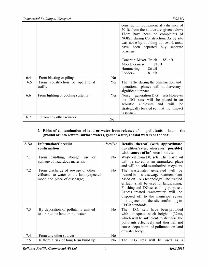
6.3 From construction or demolition Yes The noise levels (dB) generated from
FORM I
8
Commercial Building at Vikaspuri
April 2015 Reliance Prolific Commercial (P) Ltd.
construction equipment at a distance of
50 ft. from the source are given below:
There have been no complaints of NOISE during Construction. As by site
was noise by boulding out .work areas have been separted buy separate
boarings.
Concrete Mixer Truck – 85 dB
Mobile cranes- 81dB
Hammering – 86 dB
Loader - 81 dB
6.4 From blasting or piling No
6.5 From construction or operational traffic
Yes The traffic during the construction and
operational phases will not have any significant impact.
6.6 From lighting or cooling systems Yes Noise generation D.G sets However the DG sets will be placed in an
acoustic enclosure and will be
strategically located so that no impact is caused.
6.7 From any other sources
No
7. Risks of contamination of land or water from releases of pollutants into the
ground or into sewers, surface waters, groundwater, coastal waters or the sea:
S.No Information/Checklist
confirmation
Yes/No Details thereof (with approximate
quantities/rates, wherever possible)
with source of information data
7.1 From handling, storage, use or spillage of hazardous materials
No Waste oil from DG sets. The waste oil
will be stored at an earmarked place and will be sold to authorized recyclers.
7.2 From discharge of sewage or other effluents to water or the land (expected
mode and place of discharge)
No The wastewater generated will be
treated in on site sewage treatment plant based on FAB technology. The treated
effluent shall be used for landscaping; Flushing and DG set cooling purposes. Excess treated wastewater will be
disposed off to the municipal sewer line adjacent to the site conforming to CPCB standards.
7.3 By deposition of pollutants emitted to air into the land or into water
No The D.G sets have been provided with adequate stack heights (32m),
which will be sufficient to disperse the pollutants effectively and thus will not
cause deposition of pollutants on land
or water body.
7.4 From any other sources No
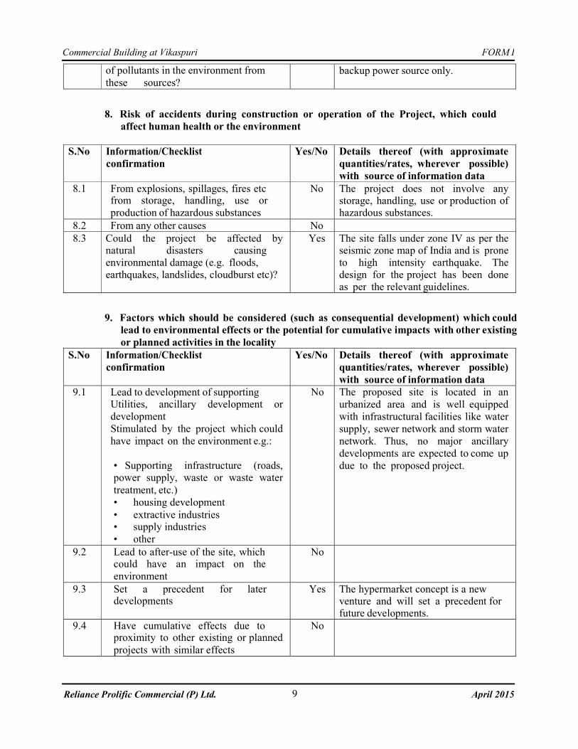
7.5 Is there a risk of long term build up No The D.G sets will be used as a
FORM I
9
Commercial Building at Vikaspuri
April 2015 Reliance Prolific Commercial (P) Ltd.
of pollutants in the environment from
these sources?
backup power source only.
8. Risk of accidents during construction or operation of the Project, which could
affect human health or the environment
S.No Information/Checklist
confirmation
Yes/No Details thereof (with approximate
quantities/rates, wherever possible)
with source of information data
8.1 From explosions, spillages, fires etc from storage, handling, use or
production of hazardous substances
No The project does not involve any storage, handling, use or production of hazardous substances.
8.2 From any other causes No
8.3 Could the project be affected by natural disasters causing
environmental damage (e.g. floods,
earthquakes, landslides, cloudburst etc)?
Yes The site falls under zone IV as per the seismic zone map of India and is prone
to high intensity earthquake. The
design for the project has been done
as per the relevant guidelines.
9. Factors which should be considered (such as consequential development) which could
lead to environmental effects or the potential for cumulative impacts with other existing
or planned activities in the locality
S.No Information/Checklist
confirmation
Yes/No Details thereof (with approximate
quantities/rates, wherever possible)
with source of information data
9.1 Lead to development of supporting Utilities, ancillary development or
development
Stimulated by the project which could
have impact on the environment e.g.:
• Supporting infrastructure (roads,
power supply, waste or waste water
treatment, etc.)
• housing development
• extractive industries • supply industries
• other
No The proposed site is located in an
urbanized area and is well equipped
with infrastructural facilities like water
supply, sewer network and storm water
network. Thus, no major ancillary
developments are expected to come up
due to the proposed project.
9.2 Lead to after-use of the site, which could have an impact on the
environment
No
9.3 Set a precedent for later developments
Yes The hypermarket concept is a new venture and will set a precedent for future developments.
9.4 Have cumulative effects due to proximity to other existing or planned
projects with similar effects
No
FORM I
10
Commercial Building at Vikaspuri
April 2015 Reliance Prolific Commercial (P) Ltd.
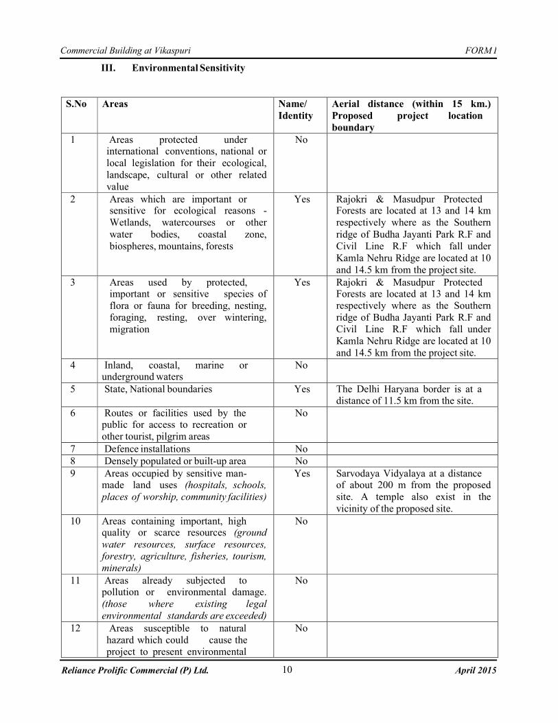
III. Environmental Sensitivity
S.No Areas Name/
Identity
Aerial distance (within 15 km.)
Proposed project location
boundary
1 Areas protected under international conventions, national or
local legislation for their ecological,
landscape, cultural or other related
value
No
2 Areas which are important or sensitive for ecological reasons -
Wetlands, watercourses or other
water bodies, coastal zone,
biospheres, mountains, forests
Yes Rajokri & Masudpur Protected Forests are located at 13 and 14 km
respectively where as the Southern
ridge of Budha Jayanti Park R.F and
Civil Line R.F which fall under
Kamla Nehru Ridge are located at 10
and 14.5 km from the project site.
3 Areas used by protected, important or sensitive species of
flora or fauna for breeding, nesting,
foraging, resting, over wintering,
migration
Yes Rajokri & Masudpur Protected Forests are located at 13 and 14 km
respectively where as the Southern
ridge of Budha Jayanti Park R.F and
Civil Line R.F which fall under
Kamla Nehru Ridge are located at 10
and 14.5 km from the project site.
4 Inland, coastal, marine or underground waters
No
5 State, National boundaries Yes The Delhi Haryana border is at a distance of 11.5 km from the site.
6 Routes or facilities used by the public for access to recreation or
other tourist, pilgrim areas
No
7 Defence installations No
8 Densely populated or built-up area No
9 Areas occupied by sensitive man- made land uses (hospitals, schools,
places of worship, community facilities)
Yes Sarvodaya Vidyalaya at a distance of about 200 m from the proposed
site. A temple also exist in the
vicinity of the proposed site.
10 Areas containing important, high quality or scarce resources (ground
water resources, surface resources,
forestry, agriculture, fisheries, tourism,
minerals)
No
11 Areas already subjected to pollution or environmental damage.
(those where existing legal
environmental standards are exceeded)
No
12 Areas susceptible to natural
hazard which could cause the
project to present environmental
No
FORM I
11
Commercial Building at Vikaspuri
April 2015 Reliance Prolific Commercial (P) Ltd.
problems (earthquakes,
subsidence, landslides, erosion,
flooding or extreme or adverse
climatic conditions)
IV. Proposed Terms of Reference for EIA studies
The proposed terms of reference for Environmental assessment studies would involve following
steps:
• Evaluation of present environmental status through analysis of generated and collected
baseline data for one season. The baseline monitoring would be carried out as per
MoEF/SPCB guidelines. All the monitoring stations and frequency / schedule for the various
monitoring would be conducted as per the MoEF / SPCB guidelines. The data generated
would be analysed at the laboratory approved by MoEF / SPCB.
• Assessing the probable impact on the environmental factors due to implementation of the
project with respect to the existing scenario. This would include evaluation on various
environmental attributes such as ambient air quality, water quality, noise and vibration,
ecological and socio-economic impact within the study area. MoEF approved models would
be used for impact evaluation of various environmental parameters.
• Analysing the predicted impact with respect to the regulatory environmental standards.
• Developing an Environment Management Plan for the proposed project to mitigate any
negative significant impacts that would arise from the proposed project. Environment
Management plan would be formulated for the mitigation of the identified adverse
impacts. The plan would formulate and describe proposed environmental safeguards and
monitoring of the following aspects:
• Measures to control air and water pollution.
• Measures to arrest the generation of noise.
• Proper plans for wastewater management.
• Proper methods for disposal of solid wastes.
• Post project environmental quality monitoring program.
• Initiatives like Rain Water Harvesting etc.
Reliance Prolific Commercial Pvt Ltd
207020-A i
CENGRS GEOTECHNICA PVT. LTD. Job No. Sheet No.
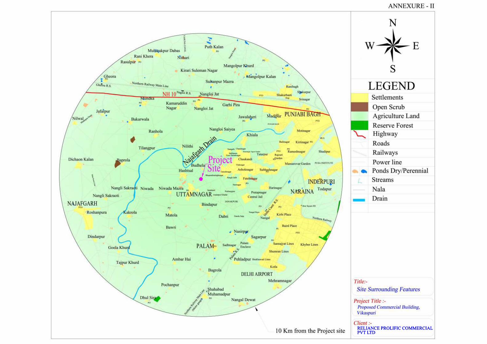
REPORT ON :
GEOTECHNICAL INVESTIGATION FOR
PROPOSED COMMUNITY CENTRE PLOT NO. A, BLOCK-A, VIKAS PURI
NEW DELHI
Submitted to:
M/s. Majestic Agrotech (P) Ltd. 84-A, Mittal Court 224, Nariman Point,
Mumbai-400021.
207020-A ii
CENGRS GEOTECHNICA PVT. LTD. Job No. Sheet No.
TABLE OF CONTENTS Sheet No. 1.0 INTRODUCTION 1 1.1 Project Description 1 1.2 Purposes of Study 1 2.0 FIELD INVESTIGATIONS 1 2.1 Soil Borings 1 2.2 Dynamic Cone Penetration Test 2 2.3 Groundwater 3 3.0 LABORATORY TESTS 3 4.0 GENERAL SITE CONDITIONS 4 4.1 Regional Geology 4 4.2 Site Stratigraphy 4 4.3 Groundwater 5 5.0 FOUNDATION ANALYSIS AND RECOMMENDATIONS 5 5.1 General 5 5.2 Foundation Type and Depth 5 5.3 Open Foundations 6 5.4 Definition of Gross and Net Bearing Pressure 8 5.5 Basement Design 8 5.6 Liquefaction Potential 9 6.0 FOUNDATION CONSTRUCTION CONSIDERATIONS 9 6.1 Excavation 9 6.2 Foundation Level Preparation 10 6.3 Backfilling 10 6.4 Chemical Attack 10 6.5 Variability in Subsurface Conditions 12 7.0 SUMMARY OF PRINCIPAL FINDINGS AND
RECOMMENDATIONS 12
8.0 CLOSURE 13
207020-A iii
CENGRS GEOTECHNICA PVT. LTD. Job No. Sheet No.
TABLES Table No. Soil Profiles 1 to 5 Engineering Description of Soil 6 Uncertainty in Laboratory measurements 7 Chemical Test Results 8
ILLUSTRATIONS
Fig. No. Plan of field investigation 1 Dynamic Cone Penetration Test Results 2 Summary of Borehole Profile 3 Standard Penetration Test Results 4
Grain Size Analysis 5 to 16 Shear Test Results 17 to 34 Consolidation Test Results 35 & 36
Typical Calculations : Sheet Nos. 1 to 2 --------------------------------------------------------
207020-A 1
CENGRS GEOTECHNICA PVT. LTD. Job No. Sheet No.
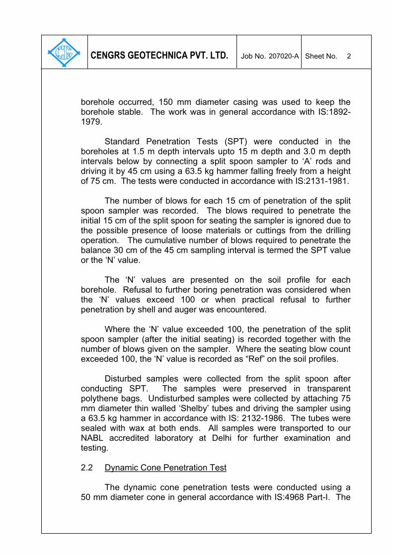
1.0 INTRODUCTION
1.1 Project Description
M/s. Majestic Agrotech(P)Ltd. is planning to construct various Greenfield Commercial Outlet Projects in Delhi.This report presents the results of Community Centre on Plot No. A in Block-A, Vikaspuri, New Delhi.
The plot covers an area of 13628 m2. The ground coverage
shall be 3174 m2 for building and 680 m2 for atrium. The building will have a height of 26 m and shall have three basements. A layout plan showing the locations of our field investigation is illustrated on Fig.1.
1.2 Purposes of Study
The overall purposes of this study are to investigate the stratigraphy at the site and to develop geotechnical recommendations for foundation design and construction. To accomplish these purposes, the study was conducted in the following phases: (a) drilling five boreholes to 30 m depth or refusal whichever is
earlier in order to determine site stratigraphy and to collect disturbed and undisturbed soil samples for laboratory testing;
(b) conducting five dynamic cone penetration tests to 10 m depth or
refusal, so as to obtain additional data for foundation analysis. (c) testing selected soil samples in the laboratory to determine
pertinent index and engineering properties of the soils; and (d) analyzing all field and laboratory data in order to develop
engineering recommendations for foundation design and construction.
2.0 FIELD INVESTIGATION
2.1 Soil Borings The boreholes were progressed using a mechanized shell and auger to the specified depth or refusal, whichever is encountered earlier. The borehole diameter was 150 mm. Where caving of the
207020-A 2
CENGRS GEOTECHNICA PVT. LTD. Job No. Sheet No.
borehole occurred, 150 mm diameter casing was used to keep the borehole stable. The work was in general accordance with IS:1892-1979. Standard Penetration Tests (SPT) were conducted in the boreholes at 1.5 m depth intervals upto 15 m depth and 3.0 m depth intervals below by connecting a split spoon sampler to ‘A’ rods and driving it by 45 cm using a 63.5 kg hammer falling freely from a height of 75 cm. The tests were conducted in accordance with IS:2131-1981.
The number of blows for each 15 cm of penetration of the split spoon sampler was recorded. The blows required to penetrate the initial 15 cm of the split spoon for seating the sampler is ignored due to the possible presence of loose materials or cuttings from the drilling operation. The cumulative number of blows required to penetrate the balance 30 cm of the 45 cm sampling interval is termed the SPT value or the ‘N’ value.
The ‘N’ values are presented on the soil profile for each borehole. Refusal to further boring penetration was considered when the ‘N’ values exceed 100 or when practical refusal to further penetration by shell and auger was encountered. Where the ‘N’ value exceeded 100, the penetration of the split spoon sampler (after the initial seating) is recorded together with the number of blows given on the sampler. Where the seating blow count exceeded 100, the ‘N’ value is recorded as “Ref” on the soil profiles. Disturbed samples were collected from the split spoon after conducting SPT. The samples were preserved in transparent polythene bags. Undisturbed samples were collected by attaching 75 mm diameter thin walled ‘Shelby’ tubes and driving the sampler using a 63.5 kg hammer in accordance with IS: 2132-1986. The tubes were sealed with wax at both ends. All samples were transported to our NABL accredited laboratory at Delhi for further examination and testing. 2.2 Dynamic Cone Penetration Test
The dynamic cone penetration tests were conducted using a
50 mm diameter cone in general accordance with IS:4968 Part-I. The
207020-A 3
CENGRS GEOTECHNICA PVT. LTD. Job No. Sheet No.
cone is attached to ‘A’ rods and driven by means of 63.5 kg hammer falling freely from a height of 75 cm. The number of blows required for each 30 cm penetration of the cone is recorded. In order to limit the friction between the rods and the soil, the rods are rotated after every 1 to 1.5 m of cone penetration. Results are presented as blows per 30 cm penetration versus depth on Fig. No. 2. 2.3 Groundwater
Groundwater level was measured in the boreholes 24 hours
after drilling and sampling was completed. The measured water levels are recorded on the individual soil profiles.
3.0 LABORATORY TESTS
The laboratory testing has been carried out in our NABL accredited laboratory. The quality procedures in our laboratory conform to ISO/IEC-17025-2005.
The laboratory testing programme was aimed at verifying the field classifications and developing parameters for engineering analysis. All testing was performed in accordance with the current applicable IS specifications. The following tests were conducted on selected soil and water samples recovered from the boreholes:
Laboratory Tests IS : Code Referred Bulk density & natural moisture content IS : 2720 (Part-2) -1973 Specific gravity IS : 2720 (Part-3) -1980 Grain size analysis IS : 2720 (Part-4) -1985 Liquid & plastic limit IS : 2720 (Part-5) -1985 Unconfined compression test IS : 2720 (Part-10) -1991 Unconsolidated undrained triaxial shear test IS : 2720 (Part-11) -1993 Consolidated drained direct shear test IS : 2720 (Part-13)-1986 Consolidation Test IS : 2720 (Part-15)-1986
pH value IS : 2720 (Part-26) -1987 Sulphate content IS : 2720 (Part-27) -1977 Chemical analysis*
of soil to determine Chloride content IS : 3025 (Part-32)-1993 pH value IS : 3025 (Part-11) -1996 Sulphate content IS : 3025 (Part-24) -1998 Chemical analysis*
for water to determine Chloride content IS : 3025 (Part-32)-1993 * outside NABL Scope
207020-A 4
CENGRS GEOTECHNICA PVT. LTD. Job No. Sheet No.
All test results are presented in the illustration section of this report. A note on our NABL accreditation together with the uncertainty in laboratory measurements is presented on Table 7.
4.0 GENERAL SITE CONDITIONS 4.1 Regional Geology
The soils at the project site belong to the “Indo Gangetic Alluvium”(1) and are river deposits of the Yamuna and its tributaries. The Pleistocene and Recent Deposits of the Indo-Gangetic Basin are composed of gravels, sands, silts and clays with remains of animal and plants. The older alluvium is rather dark coloured (locally called “Bhanger”) and is generally rich in concretions of nodules of impure calcium carbonate (Kankars). The kankars are of all shapes and sizes, varying from small sand sized grains to big lumps. The age of the “Bhanger” alluvium is Middle to Upper Pleistocene.
The newer alluvium (locally called “Khadar”) is light coloured and
poor in concretions. It contains lenticular beds of sand and gravel as well as peat beds. It is merged by insensible gradations into the Recent or deltaic alluvia and its age is Upper Pleistocene to Recent. 4.2 Site Stratigraphy
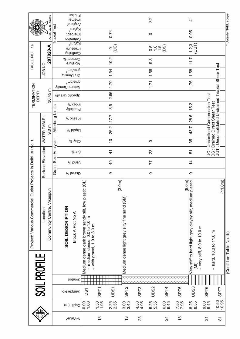
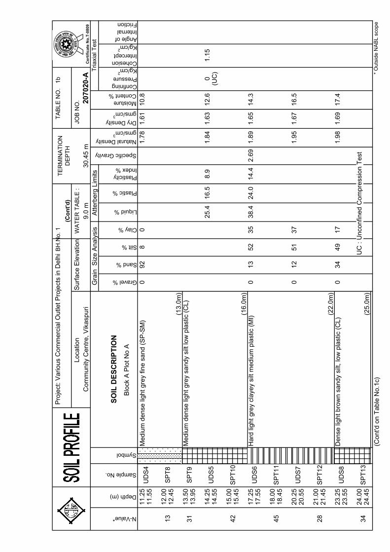
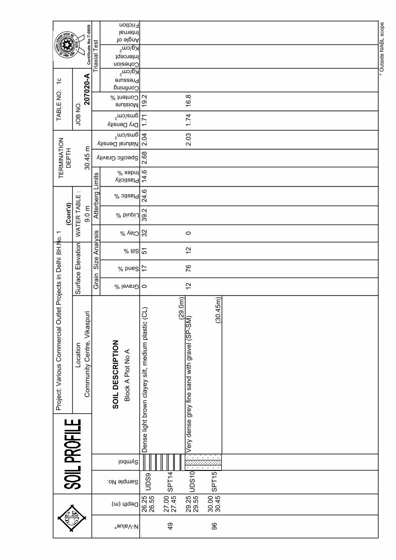
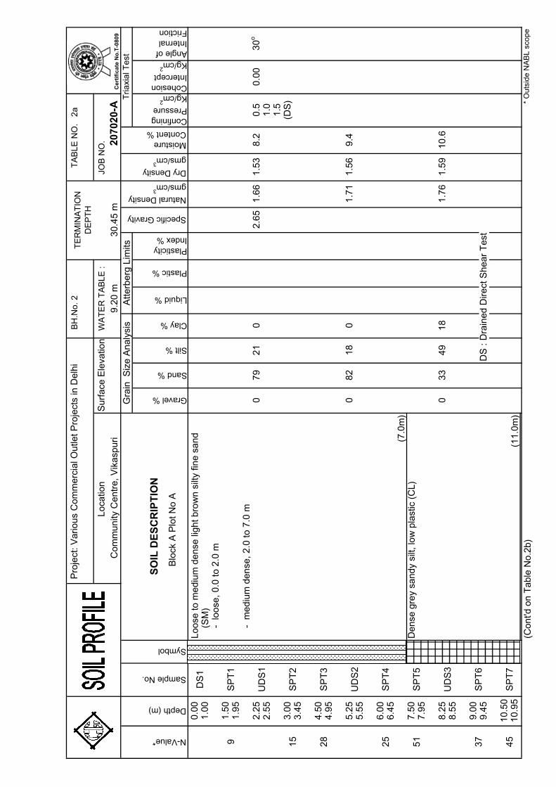
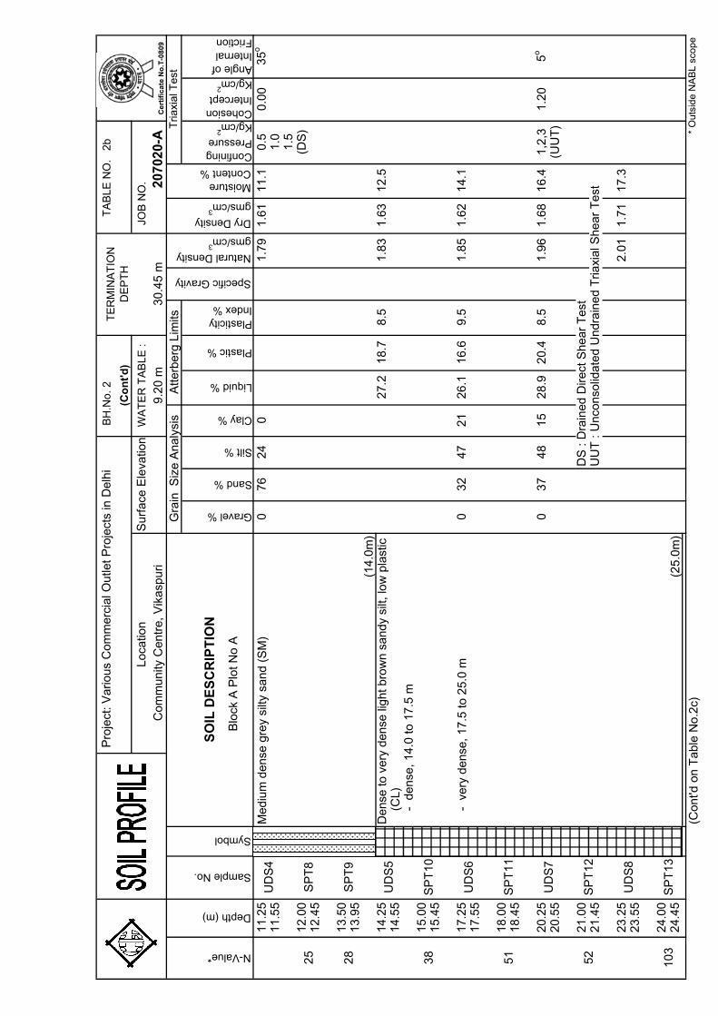
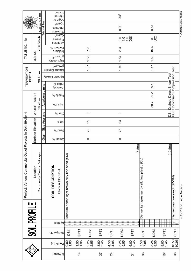
The soils at the site are alluvial in nature and consist of
alternating layers of silty sand / fine sand and sandy silt/clayey silt from the ground surface to the final explored depth of 30 m. Silty sand is met from the ground surface to about 7-8 m depth. This is underlain by sandy silt to about 11 m depth and silty sand to about 13-14 m depth. Sandy silty / clayey silt is then met to about 26-29 m depth. However, at BH-4, sand is met below 10.5 m depth that extends to the final explored depth of 30 m.
(1) Krishnan, M.S. (1986), “Geology of India & Burma”, CBS Publishers, New Delhi.
207020-A 5
CENGRS GEOTECHNICA PVT. LTD. Job No. Sheet No.
SPT N-values range from 9 to 15 to 3.0 m depth with some
higher values. However, at BH-5, SPT value of 5 is encountered at 1.5 m depth. Below this, SPT values generally range from 18 to 33 to about 10.0 m depth from 25 to 55 to about 20 to 21 m depth and from 28 to more than 100 to the final explored depth of 30.0 m.
DCPT values range from 8 to 15 to 2.0 m depth with some
higher values. Below this, DCPT values range from 16 to 34 to 7.0 m depth and from 35 to 50 to final test depth of 10.0 m.
Detailed description of the materials encountered at the
borehole locations is presented on the individual soil profiles on Table 1 to 5. Engineering terms used for describing soils are explained on Table 6. Chemical test results are presented on Table 8. All laboratory data are presented graphically in the illustrations. A summary of the borehole profiles is presented on Fig. 3. Standard penetration test results are presented on Fig. 4.
4.3 Groundwater
Based on the measurements in the completed boreholes, groundwater was met between 9.0 to 11.0 m depth below existing ground level at the time of our field investigation (February, 2007). Fluctuations may occur in measured water levels due to seasonal variations in rainfall and surface evaporation rates.
5.0 FOUNDATION ANALYSIS AND RECOMMENDATIONS
5.1 General A suitable foundation for any structure should have an adequate factor of safety against exceeding the bearing capacity of the supporting soils. Also the vertical movements due to compression of the soils should be within tolerable limits for the structure. We consider that foundation designed in accordance with the recommendations given herein will satisfy these criteria.
5.2 Foundation Type and Depth
We understand that building will have a height of 26 m and shall have three basements. Individual isolated footings with interconnecting
207020-A 6
CENGRS GEOTECHNICA PVT. LTD. Job No. Sheet No.
beams or RCC strip footings (T-beam and slab) may be provided. Raft foundation is also a suitable foundation scheme.
For lightly loaded structures such as boundary wall etc., we recommend a minimum foundation embedment depth of 1.2~1.5 m 5.3 Open Foundations
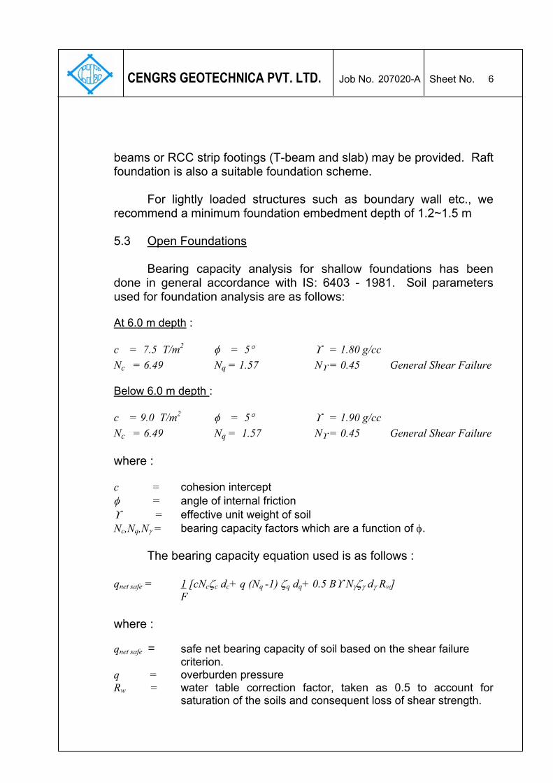
Bearing capacity analysis for shallow foundations has been done in general accordance with IS: 6403 - 1981. Soil parameters used for foundation analysis are as follows: At 6.0 m depth : c = 7.5 T/m2 φ = 5° ϒ = 1.80 g/cc Nc = 6.49 Nq = 1.57 Nϒ = 0.45 General Shear Failure Below 6.0 m depth : c = 9.0 T/m2 φ = 5° ϒ = 1.90 g/cc Nc = 6.49 Nq = 1.57 Nϒ = 0.45 General Shear Failure where : c = cohesion intercept φ = angle of internal friction ϒ = effective unit weight of soil Nc,Nq,Nγ = bearing capacity factors which are a function of φ. The bearing capacity equation used is as follows : qnet safe = 1 [cNcζc dc+ q (Nq -1) ζq dq+ 0.5 Bϒ Nγζγ dγ Rw] F where : qnet safe = safe net bearing capacity of soil based on the shear failure criterion. q = overburden pressure Rw = water table correction factor, taken as 0.5 to account for
saturation of the soils and consequent loss of shear strength.
207020-A 7
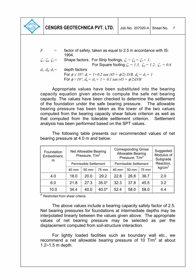
CENGRS GEOTECHNICA PVT. LTD. Job No. Sheet No.
F = factor of safety, taken as equal to 2.5 in accordance with IS: 1904. ζc, ζq, ζγ = Shape factors. For Strip footings, ζc = ζq = ζγ = 1. For Square footing ζc = 1.3, ζq = 1.2, ζγ = 0.6 dc, dq, dγ = depth factors For φ ≤ 10°, dc = 1+0.2 tan (45 + φ/2) D/B, dq = dγ = 1 For φ >10°, dq = dγ = 1 + 0.1 tan (45 + φ/2)D/B
Appropriate values have been substituted into the bearing
capacity equation given above to compute the safe net bearing capacity. The values have been checked to determine the settlement of the foundation under the safe bearing pressure. The allowable bearing pressure has been taken as the lower of the two values computed from the bearing capacity shear failure criterion as well as that computed from the tolerable settlement criterion. Settlement analysis has been performed based on the SPT values.
The following table presents our recommended values of net
bearing pressure at 4.0 m and below.
Net Allowable Bearing Pressure, T/m2
Corresponding Gross Allowable Bearing
Pressure, T/m2
Permissible Settlement Permissible Settlement
Foundation Embedment,
m
40 mm 50 mm 75 mm 40 mm 50 mm 75 mm
Suggested Modulus of Subgrade Reaction,
kg/cm3
4.0 16.0 20.0 29.2 22.8 26.8 36.7 2.0 6.0 21.8 27.3 35.0* 32.3 37.8 45.5 3.2
10.0 34.4 40.0 40.0* 52.4 58.0 58.0 4.4 * Restricted from shear criteria
The above values include a bearing capacity safety factor of 2.5.
Net bearing pressures for foundations at intermediate depths may be interpolated linearly between the values given above. The appropriate values of net bearing pressure may be selected as per the displacement computed from soil-structure interaction.
For lightly loaded facilities such as boundary wall etc., we
recommend a net allowable bearing pressure of 10 T/m2 at about 1.2~1.5 m depth.
207020-A 8
CENGRS GEOTECHNICA PVT. LTD. Job No. Sheet No.
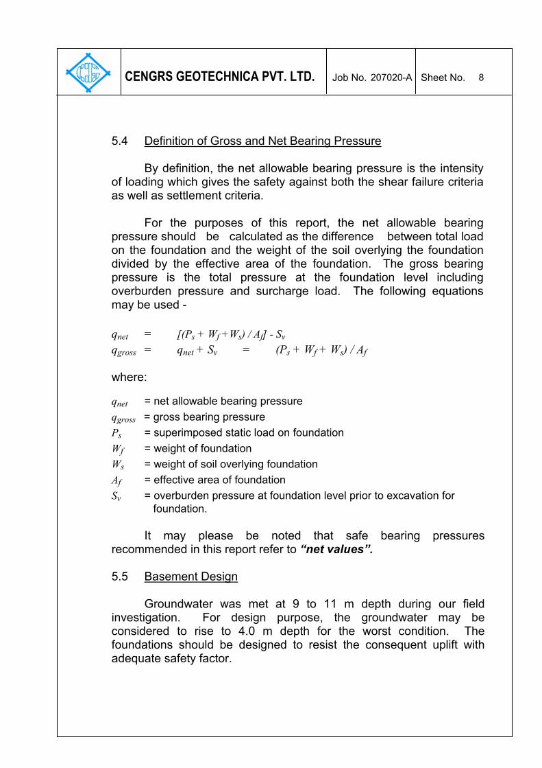
5.4 Definition of Gross and Net Bearing Pressure
By definition, the net allowable bearing pressure is the intensity
of loading which gives the safety against both the shear failure criteria as well as settlement criteria.
For the purposes of this report, the net allowable bearing
pressure should be calculated as the difference between total load on the foundation and the weight of the soil overlying the foundation divided by the effective area of the foundation. The gross bearing pressure is the total pressure at the foundation level including overburden pressure and surcharge load. The following equations may be used - qnet = [(Ps + Wf +Ws) / Af] - Sv qgross = qnet + Sv = (Ps + Wf + Ws) / Af where:
qnet = net allowable bearing pressure qgross = gross bearing pressure Ps = superimposed static load on foundation Wf = weight of foundation Ws = weight of soil overlying foundation Af = effective area of foundation Sv = overburden pressure at foundation level prior to excavation for foundation.
It may please be noted that safe bearing pressures
recommended in this report refer to “net values”. 5.5 Basement Design Groundwater was met at 9 to 11 m depth during our field investigation. For design purpose, the groundwater may be considered to rise to 4.0 m depth for the worst condition. The foundations should be designed to resist the consequent uplift with adequate safety factor.
207020-A 9
CENGRS GEOTECHNICA PVT. LTD. Job No. Sheet No.
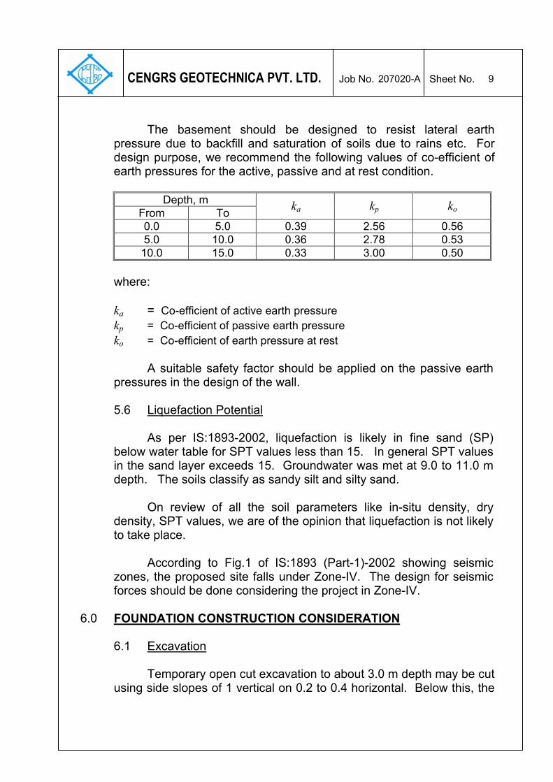
The basement should be designed to resist lateral earth pressure due to backfill and saturation of soils due to rains etc. For design purpose, we recommend the following values of co-efficient of earth pressures for the active, passive and at rest condition.
Depth, m From To ka kp ko 0.0 5.0 0.39 2.56 0.56 5.0 10.0 0.36 2.78 0.53 10.0 15.0 0.33 3.00 0.50
where: ka = Co-efficient of active earth pressure kp = Co-efficient of passive earth pressure ko = Co-efficient of earth pressure at rest A suitable safety factor should be applied on the passive earth pressures in the design of the wall. 5.6 Liquefaction Potential
As per IS:1893-2002, liquefaction is likely in fine sand (SP) below water table for SPT values less than 15. In general SPT values in the sand layer exceeds 15. Groundwater was met at 9.0 to 11.0 m depth. The soils classify as sandy silt and silty sand.
On review of all the soil parameters like in-situ density, dry
density, SPT values, we are of the opinion that liquefaction is not likely to take place.
According to Fig.1 of IS:1893 (Part-1)-2002 showing seismic
zones, the proposed site falls under Zone-IV. The design for seismic forces should be done considering the project in Zone-IV.
6.0 FOUNDATION CONSTRUCTION CONSIDERATION
6.1 Excavation Temporary open cut excavation to about 3.0 m depth may be cut
using side slopes of 1 vertical on 0.2 to 0.4 horizontal. Below this, the
207020-A 10
CENGRS GEOTECHNICA PVT. LTD. Job No. Sheet No.
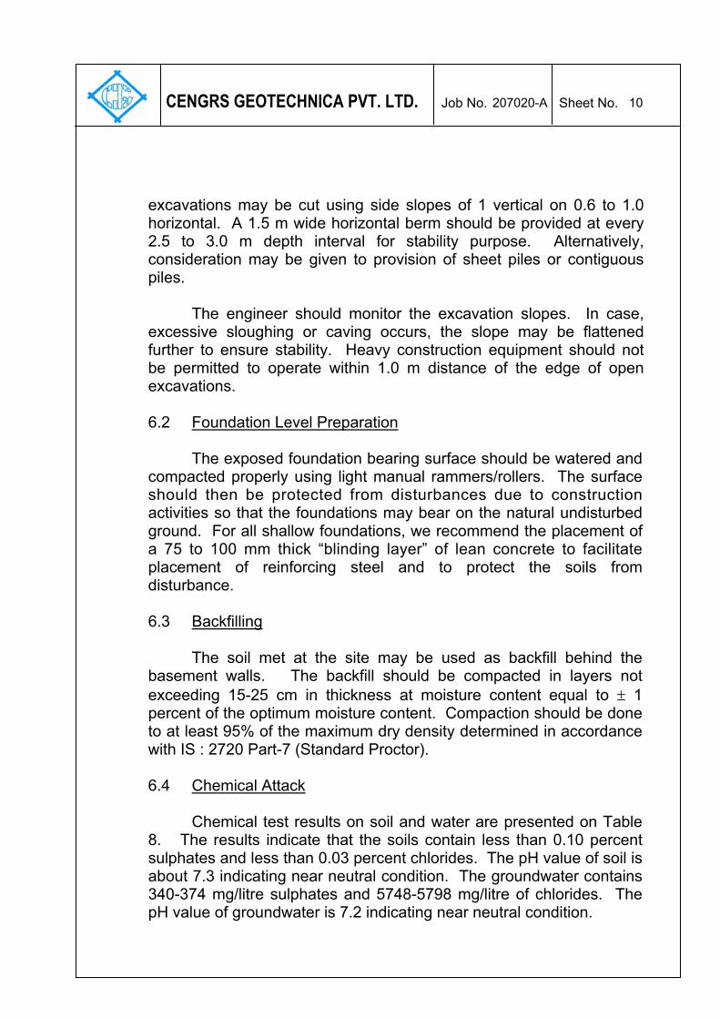
excavations may be cut using side slopes of 1 vertical on 0.6 to 1.0 horizontal. A 1.5 m wide horizontal berm should be provided at every 2.5 to 3.0 m depth interval for stability purpose. Alternatively, consideration may be given to provision of sheet piles or contiguous piles.
The engineer should monitor the excavation slopes. In case,
excessive sloughing or caving occurs, the slope may be flattened further to ensure stability. Heavy construction equipment should not be permitted to operate within 1.0 m distance of the edge of open excavations. 6.2 Foundation Level Preparation
The exposed foundation bearing surface should be watered and compacted properly using light manual rammers/rollers. The surface should then be protected from disturbances due to construction activities so that the foundations may bear on the natural undisturbed ground. For all shallow foundations, we recommend the placement of a 75 to 100 mm thick “blinding layer” of lean concrete to facilitate placement of reinforcing steel and to protect the soils from disturbance.
6.3 Backfilling
The soil met at the site may be used as backfill behind the basement walls. The backfill should be compacted in layers not exceeding 15-25 cm in thickness at moisture content equal to ± 1 percent of the optimum moisture content. Compaction should be done to at least 95% of the maximum dry density determined in accordance with IS : 2720 Part-7 (Standard Proctor). 6.4 Chemical Attack
Chemical test results on soil and water are presented on Table
8. The results indicate that the soils contain less than 0.10 percent sulphates and less than 0.03 percent chlorides. The pH value of soil is about 7.3 indicating near neutral condition. The groundwater contains 340-374 mg/litre sulphates and 5748-5798 mg/litre of chlorides. The pH value of groundwater is 7.2 indicating near neutral condition.
207020-A 11
CENGRS GEOTECHNICA PVT. LTD. Job No. Sheet No.
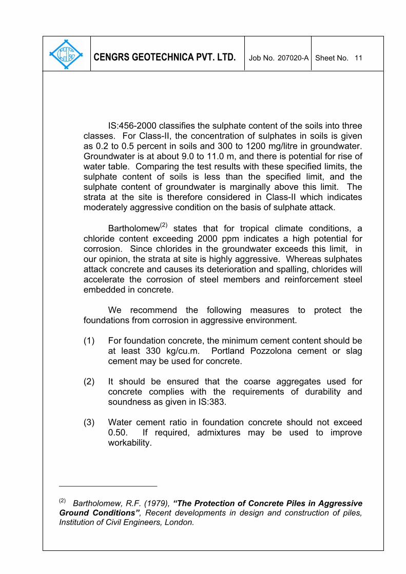
IS:456-2000 classifies the sulphate content of the soils into three classes. For Class-II, the concentration of sulphates in soils is given as 0.2 to 0.5 percent in soils and 300 to 1200 mg/litre in groundwater. Groundwater is at about 9.0 to 11.0 m, and there is potential for rise of water table. Comparing the test results with these specified limits, the sulphate content of soils is less than the specified limit, and the sulphate content of groundwater is marginally above this limit. The strata at the site is therefore considered in Class-II which indicates moderately aggressive condition on the basis of sulphate attack. Bartholomew(2) states that for tropical climate conditions, a chloride content exceeding 2000 ppm indicates a high potential for corrosion. Since chlorides in the groundwater exceeds this limit, in our opinion, the strata at site is highly aggressive. Whereas sulphates attack concrete and causes its deterioration and spalling, chlorides will accelerate the corrosion of steel members and reinforcement steel embedded in concrete. We recommend the following measures to protect the foundations from corrosion in aggressive environment.
(1) For foundation concrete, the minimum cement content should be
at least 330 kg/cu.m. Portland Pozzolona cement or slag cement may be used for concrete.
(2) It should be ensured that the coarse aggregates used for
concrete complies with the requirements of durability and soundness as given in IS:383.
(3) Water cement ratio in foundation concrete should not exceed
0.50. If required, admixtures may be used to improve workability.
(2) Bartholomew, R.F. (1979), “The Protection of Concrete Piles in Aggressive Ground Conditions”, Recent developments in design and construction of piles, Institution of Civil Engineers, London.
207020-A 12
CENGRS GEOTECHNICA PVT. LTD. Job No. Sheet No.
(4) A clear concrete cover over the reinforcement steel of at least
50 mm should be provided for all foundations. (5) Foundation concrete should be densified adequately using a
vibrator so as to form a dense impervious mass. Honeycombing of concrete or other defects can accelerate the corrosion process. Therefore, adequate quality control should be exercised on site to ensure good quality concrete of low permeability.
(6) The mixing water and curing water for foundations concrete
should be tested and suitable water conforming to IS:456 should be used for concreting and curing.
(7) Corrosion resistant steel (CRS) may be provided for
reinforcement steel. Alternatively, epoxy coating may be provided on the tor steel reinforcement.
6.5 Variability in Subsurface Conditions
Subsurface conditions encountered during construction may vary somewhat from the conditions encountered during the site investigation. In case significant variations are encountered during construction, we request to be notified so that our engineers may review the recommendations in this report in light of these variations.
7.0 SUMMARY OF PRINCIPAL FINDINGS AND RECOMMENDATIONS
M/s. Cengrs Geotechnica Private Limited conducted a
geotechnical investigation for Commercial Outlet Project at Community Centre, Block-A, Vikaspuri in New Delhi. The scope of work included five boreholes to 30 m depth and five dynamic cone penetration tests to 10 m depth.
The soils at the site are alluvial in nature and consist of
alternating layers of silty sand / fine sand and sandy silt / clayey silt from the ground surface to final explored depth of 30 m. Groundwater was met between 9.0 and 11.0 m depth below existing ground level at the time of our field investigation (February, 2007).
207020-A 13
CENGRS GEOTECHNICA PVT. LTD. Job No. Sheet No.
Isolated foundations with a connecting beams, RCC strip
footings (T-beam and slab) and raft foundation are suitable foundation schemes. Net bearing pressures for different settlements are given in Section 5.3 of this report. The appropriate net bearing pressure may be selected for the desired settlement as computed from soil-structure interaction.
8.0 CLOSURE
We appreciate the opportunity to perform this investigation for you and have pleasure in submitting this report. Please contact us when we can be of further service to you.
for CENGRS GEOTECHNICA PRIVATE LIMITED
(RAVI SUNDARAM) (SANJAY GUPTA) DIRECTOR MANAGING DIRECTOR
Pro
ject
: V
arious
Com
mer
cial
Outle
t P
roje
cts
in D
elh
iB
H.N
o.
1
TA
BL
E N
O.
1
a
JO
B N
O.
Gravel %
Sand %
Silt %
Clay %
Liquid %
Plastic %
Plasticity Index %
Confining Pressure
Kg/cm2
Cohesion Intercept
Kg/cm2
Angle of Internal Friction
0.0
01.0
0
1.5
01.9
5
2.2
59
40
41
10
26.2
17.7
8.5
2.6
61.7
01.5
410.2
00.7
42.5
5(U
C)
3.0
03.4
5
4.5
04.9
5
5.2
50
77
23
01.7
11.5
69.8
0.5
032o
5.5
51.0
1.5
6.0
0(D
S)
6.4
5
7.5
07.9
5
8.2
50
14
51
35
43.7
28.5
15.2
1.7
61.5
811.7
1,2
,30.9
54
o
8.5
5(U
UT
)
9.0
09.4
5U
C :
Un
con
fine
d C
om
pre
ssio
n T
est
DS
: D
rain
ed D
irect
Shear
Test
10.5
0U
UT
: U
nco
nso
lidate
d U
ndra
ined T
riaxi
al S
hear
Test
10.9
5
(Cont'd
on T
able
No.1
b)
(3.0
m)
Surf
ace
Ele
vatio
nLoca
tion
Gra
in S
ize
Ana
lysi
s
TE
RM
INA
TIO
N
DE
PT
H
WA
TE
R T
AB
LE
:
Specific Gravity
Co
mm
un
ity C
en
tre
, V
ika
spu
ri3
0.4
5 m
9.0
m20
7020
-A
SO
IL D
ES
CR
IPT
ION
Mediu
m d
ense
dark
bro
wn s
andy
silt,
low
pla
stic
(C
L)
-
very
stif
f, 8
.0 to 1
0.0
m
- m
ed
ium
de
nse
, 0
.0 t
o 1
.0 m
-
with
gra
vel,
1.0
to 3
.0 m
13
SP
T1
13
UD
S1
Moisture Content %
Very
stif
f to h
ard
light g
rey
claye
y si
lt, m
ediu
m p
last
ic
(M
I)
Mediu
m d
ense
light g
rey
silty
fine s
and (
SM
)
(8.0
m)
Tria
xia
l Te
st
DS
1
N-Value*
Depth (m)
Sample No.
Symbol
Natural Density
gms/cm3
Dry Density
gms/cm3
Atterb
erg
Lim
its
UD
S2
23
SP
T3
24
21
SP
T6
SP
T2
-
hard
, 10.0
to 1
1.0
m
18
SP
T5
UD
S3
SP
T4
* O
uts
ide
NA
BL
sco
pe
81
SP
T7
(11
.0m
)
Ce
rtif
ica
te N
o.T
-08
09
Blo
ck A
Plo
t N
o A
Pro
ject
: V
arious
Com
mer
cial
Outle
t P
roje
cts
in D
elh
iB
H.N
o.
1
TA
BL
E N
O.
1
b
JO
B N
O.
Gravel %
Sand %
Silt %
Clay %
Liquid %
Plastic %
Plasticity Index %
Confining Pressure
Kg/cm2
Cohesion Intercept
Kg/cm2
Angle of Internal Friction
11.2
50
92
80
1.7
81.6
110.8
11.5
5
12.0
012.4
5
13.5
013.9
5
14.2
525.4
16.5
8.9
1.8
41.6
312.6
01.1
514.5
5(U
C)
15.0
015.4
5
17.2
50
13
52
35
38.4
24.0
14.4
2.6
91.8
91.6
514.3
17.5
5
18.0
018.4
5
20.2
50
12
51
37
1.9
51.6
716.5
20.5
5
21.0
021.4
5
23.2
50
34
49
17
1.9
81.6
917.4
23.5
5
24.0
0U
C :
Un
con
fine
d C
om
pre
ssio
n T
est
24.4
5
(Cont'd
on T
able
No.1
c)*
Ou
tsid
e N
AB
L s
cop
e
UD
S8
Dense
light b
row
n s
andy
silt,
low
pla
stic
(C
L)
34
SP
T13
(25
.0m
)
28
SP
T12
UD
S7
42
SP
T10
45
SP
T11
UD
S6
UD
S5
31
SP
T9
Mediu
m d
ense
light g
rey
sandy
silt
low
pla
stic
(C
L)
N-Value*
Depth (m)
Sample No.
13
SP
T8
UD
S4
Mediu
m d
ense
light gre
y fin
e s
and (
SP
-SM
)
Com
munity
Centr
e, V
ikasp
uri
SO
IL D
ES
CR
IPT
ION
Moisture Content %
9.0
m3
0.4
5 m
2070
20-A
Dry Density
gms/cm3
Tria
xia
l Te
stG
rain
Siz
e A
naly
sis
Atte
rberg
Lim
its
Specific Gravity
Natural Density
gms/cm3
Symbol
(16
.0m
)H
ard
light g
rey
claye
y si
lt m
ediu
m p
last
ic (
MI)
TE
RM
INA
TIO
N
DE
PT
H
Loca
tion
Surf
ace
Ele
vatio
nW
AT
ER
TA
BL
E :
(Co
nt'
d)
(13
.0m
)
(22
.0m
)
Ce
rtif
ica
te N
o.T
-08
09
Blo
ck A
Plo
t N
o A
Pro
ject
: V
arious
Com
mer
cial
Outle
t P
roje
cts
in D
elh
iB
H.N
o.
1
TA
BL
E N
O.
1
c
JO
B N
O.
Gravel %
Sand %
Silt %
Clay %
Liquid %
Plastic %
Plasticity Index %
Confining Pressure
Kg/cm2
Cohesion Intercept
Kg/cm2
Angle of Internal Friction
26.2
50
17
51
32
39.2
24.6
14.6
2.6
82.0
41.7
119.2
26.5
5
27.0
027.4
5
29.2
512
76
12
02.0
31.7
416.8
29.5
5
30.0
030.4
596
SP
T15
(29
.0m
)
UD
S10
Very
dense
gre
y fin
e s
and w
ith g
rave
l (S
P-S
M)
(30
.45
m)
49
SP
T14
UD
S9
Dense
light bro
wn c
laye
y si
lt, m
ediu
m p
last
ic (
CL)
Natural Density
gms/cm3
Dry Density
gms/cm3
Moisture Content %
Tria
xia
l Te
st3
0.4
5 m
2070
20-A
N-Value*
Depth (m)
Sample No.
Symbol
SO
IL D
ES
CR
IPT
ION
Gra
in S
ize A
naly
sis
Atte
rberg
Lim
its
Specific Gravity
Surf
ace
Ele
vatio
nW
AT
ER
TA
BL
E :
(Co
nt'
d)
Co
mm
un
ity C
en
tre
, V
ika
spu
ri9
.0 m
TE
RM
INA
TIO
N
DE
PT
H
* O
uts
ide
NA
BL
sco
pe
Loca
tion
Ce
rtif
ica
te N
o.T
-08
09
Blo
ck A
Plo
t N
o A
Pro
ject
: V
arious
Com
mer
cial
Outle
t P
roje
cts
in D
elh
iB
H.N
o.
2
TA
BL
E N
O.
2
a
JO
B N
O.
Gravel %
Sand %
Silt %
Clay %
Liquid %
Plastic %
Plasticity Index %
Confining Pressure
Kg/cm2
Cohesion Intercept
Kg/cm2
Angle of Internal Friction
0.0
01.0
0
1.5
01.9
5
2.2
50
79
21
02.6
51.6
61.5
38.2
0.5
0.0
030o
2.5
51.0
1.5
3.0
0(D
S)
3.4
5
4.5
04.9
5
5.2
50
82
18
01.7
11.5
69.4
5.5
5
6.0
06.4
5
7.5
07.9
5
8.2
50
33
49
18
1.7
61.5
910.6
8.5
5
9.0
09.4
5D
S : D
rain
ed D
irect
Shear
Test
10.5
010.9
5
(Cont'd
on T
able
No.2
b)
* O
uts
ide
NA
BL
sco
pe
45
SP
T7
(11
.0m
)
(7.0
m)
Dense
gre
y sa
ndy
silt,
low
pla
stic
(C
L)
37
SP
T6
SP
T2
51
SP
T5
UD
S3
SP
T4
UD
S2
28
SP
T3
25
Tria
xia
l Te
st
DS
1
N-Value*
Depth (m)
Sample No.
Symbol
Natural Density
gms/cm3
Dry Density
gms/cm3
Atterb
erg
Lim
its
Moisture Content %
9S
PT
1
15
UD
S1
2070
20-A
SO
IL D
ES
CR
IPT
ION
Loose
to m
ediu
m d
ense
light bro
wn s
ilty
fine s
and
(S
M)
-
loose
, 0.0
to 2
.0 m
- m
ed
ium
de
nse
, 2
.0 t
o 7
.0 m
TE
RM
INA
TIO
N
DE
PT
H
WA
TE
R T
AB
LE
:
Specific Gravity
Co
mm
un
ity C
en
tre
, V
ika
spu
ri3
0.4
5 m
9.2
0 m
Surf
ace
Ele
vatio
nLoca
tion
Gra
in S
ize
Ana
lysi
sC
ert
ific
ate
No
.T-0
80
9
Blo
ck A
Plo
t N
o A
Pro
ject
: V
arious
Com
mer
cial
Outle
t P
roje
cts
in D
elh
iB
H.N
o.
2
TA
BL
E N
O.
2
b
JO
B N
O.
Gravel %
Sand %
Silt %
Clay %
Liquid %
Plastic %
Plasticity Index %
Confining Pressure
Kg/cm2
Cohesion Intercept
Kg/cm2
Angle of Internal Friction
11.2
50
76
24
01.7
91.6
111.1
0.5
0.0
035o
11.5
51.0
1.5
12.0
0(D
S)
12.4
5
13.5
013.9
5
14.2
527.2
18.7
8.5
1.8
31.6
312.5
14.5
5
15.0
015.4
5
17.2
50
32
47
21
26.1
16.6
9.5
1.8
51.6
214.1
17.5
5
18.0
018.4
5
20.2
50
37
48
15
28.9
20.4
8.5
1.9
61.6
816.4
1,2
,31.2
05
o
20.5
5(U
UT
)
21.0
0D
S : D
rain
ed D
irect
Shear
Test
21.4
5U
UT
: U
nco
nso
lidate
d U
ndra
ined T
riaxi
al S
hear
Test
23.2
52.0
11.7
117.3
23.5
5
24.0
024.4
5
(Cont'd
on T
able
No.2
c)
(14
.0m
)
-
dense
, 14.0
to 1
7.5
m
TE
RM
INA
TIO
N
DE
PT
H
Loca
tion
Surf
ace
Ele
vatio
nW
AT
ER
TA
BL
E :
(Co
nt'
d)
Symbol
-
very
dense
, 17.5
to 2
5.0
m
Moisture Content %
9.2
0 m
30
.45
m20
7020
-A
Dry Density
gms/cm3
Tria
xia
l Te
stG
rain
Siz
e A
naly
sis
Atte
rberg
Lim
its
Specific Gravity
Natural Density
gms/cm3
Mediu
m d
ense
gre
y si
lty s
and (
SM
)
Com
munity
Centr
e, V
ikasp
uri
SO
IL D
ES
CR
IPT
ION
N-Value*
Depth (m)
Sample No.
25
SP
T8
UD
S4
28
SP
T9
UD
S5
Dense
to v
ery
dense
light b
row
n s
andy
silt,
low
pla
stic
(C
L)
38
SP
T10
51
SP
T11
UD
S6
UD
S7
52
SP
T12
UD
S8
103
SP
T13
(25
.0m
)*
Ou
tsid
e N
AB
L s
cop
e
Ce
rtif
ica
te N
o.T
-08
09
Blo
ck A
Plo
t N
o A
Pro
ject
: V
arious
Com
mer
cial
Outle
t P
roje
cts
in D
elh
iB
H.N
o.
2
TA
BL
E N
O.
2
c
JO
B N
O.
Gravel %
Sand %
Silt %
Clay %
Liquid %
Plastic %
Plasticity Index %
Confining Pressure
Kg/cm2
Cohesion Intercept
Kg/cm2
Angle of Internal Friction
26.2
50
19
51
30
38.7
24.1
14.6
2.6
82.0
81.7
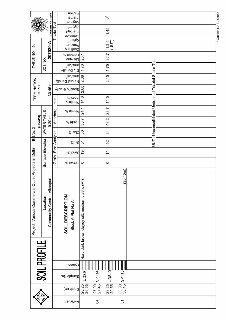
320.1
26.5
5
27.0
027.4
5
29.2
50
14
52
34
43.2
28.7
14.5
2.1
51.7
522.7
1,3
,51.4
56
o
29.5
5(U
UT
)
30.0
030.4
5
UU
T : U
nco
nso
lidate
d U
ndra
ined T
riaxi
al S
hear
Test
* O
uts
ide
NA
BL
sco
pe
Loca
tion
TE
RM
INA
TIO
N
DE
PT
H
Surf
ace
Ele
vatio
nW
AT
ER
TA
BL
E :
(Co
nt'
d)
Co
mm
un
ity C
en
tre
, V
ika
spu
ri9
.20
m3
0.4
5 m
2070
20-A
N-Value*
Depth (m)
Sample No.
Symbol
SO
IL D
ES
CR
IPT
ION
Gra
in S
ize A
naly
sis
Atte
rberg
Lim
its
Specific Gravity
Natural Density
gms/cm3
Dry Density
gms/cm3
Moisture Content %
Tria
xia
l Te
st
UD
S9
Hard
dark
bro
wn c
laye
y si
lt, m
ediu
m p
last
ic (
MI)
64
SP
T14
51
SP
T15
UD
S10
(30
.45
m)
Ce
rtif
ica
te N
o.T
-08
09
Blo
ck A
Plo
t N
o A
Pro
ject
: V
arious
Com
mer
cial
Outle
t P
roje
cts
in D
elh
BH
.No.
3
TA
BL
E N
O.
3
a
JO
B N
O.
Gravel %
Sand %
Silt %
Clay %
Liquid %
Plastic %
Plasticity Index %
Confining Pressure
Kg/cm2
Cohesion Intercept
Kg/cm2
Angle of Internal Friction
0.0
01.0
0
1.5
01.9
5
2.2
50
78
22
01.6
71.5
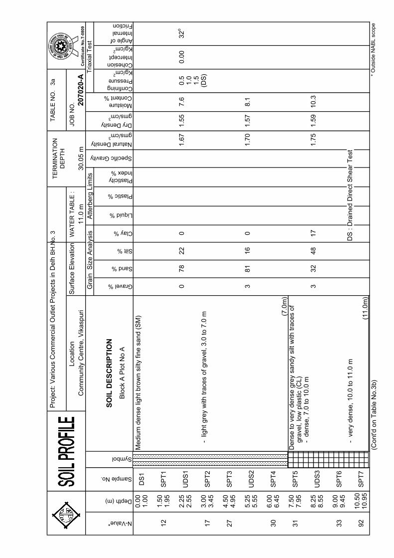
57.6
0.5
0.0
032o
2.5
51.0
1.5
3.0
0(D
S)
3.4
5
4.5
04.9
5
5.2
53
81
16
01.7
01.5
78.1
5.5
5
6.0
06.4
5
7.5
07.9
5
8.2
53
32
48
17
1.7
51.5
910.3
8.5
5
9.0
09.4
5D
S : D
rain
ed D
irect
Shear
Test
10.5
010.9
5(1
1.0
m)
(Cont'd
on T
able
No.3
b)
Surf
ace
Ele
vatio
nLoca
tion
Gra
in S
ize
Ana
lysi
s
TE
RM
INA
TIO
N
DE
PT
H
WA
TE
R T
AB
LE
:
Specific Gravity
Co
mm
un
ity C
en
tre
, V
ika
spu
ri3
0.0
5 m
11
.0 m
2070
20-A
SO
IL D
ES
CR
IPT
ION
Mediu
m d
ense
light bro
wn s
ilty
fine s
and (
SM
)
12
SP
T1
17
UD
S1
Moisture Content %
-
light gre
y w
ith tra
ces
of gra
vel,
3.0
to 7
.0 m
-
dense
, 7.0
to 1
0.0
m
Tria
xia
l Te
st
DS
1
N-Value*
Depth (m)
Sample No.
Symbol
Natural Density
gms/cm3
Dry Density
gms/cm3
Atterb
erg
Lim
its
UD
S2
27
SP
T3
30
33
SP
T6
SP
T2
-
very
dense
, 10.0
to 1
1.0
m
31
SP
T5
UD
S3
SP
T4
gra
vel,
low
pla
stic
(C
L)
(7.0
m)
Dense
to v
ery
dense
gre
y sa
ndy
silt
with
trace
s of
* O
uts
ide
NA
BL
sco
pe
92
SP
T7
Ce
rtif
ica
te N
o.T
-08
09
Blo
ck A
Plo
t N
o A
Pro
ject
: V
arious
Com
mer
cial
Outle
t P
roje
cts
in D
elh
BH
.No.
3
TA
BL
E N
O.
3
b
JO
B N
O.
Gravel %
Sand %
Silt %
Clay %
Liquid %
Plastic %
Plasticity Index %
Confining Pressure
Kg/cm2
Cohesion Intercept
Kg/cm2
Angle of Internal Friction
11.2
50
77
23
01.8
31.6
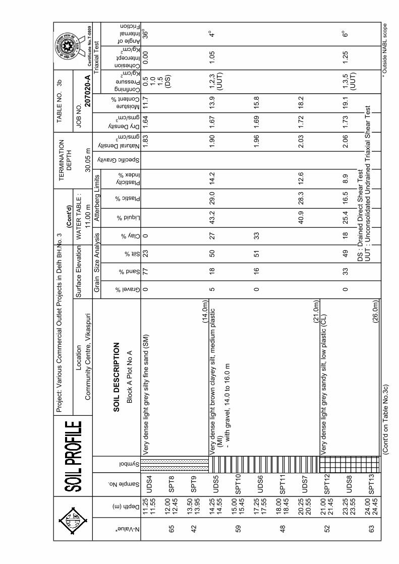
411.7
0.5
0.0
036o
11.5
51.0
1.5
12.0
0(D
S)
12.4
5
13.5
013.9
5
14.2
55
18
50
27
43.2
29.0
14.2
1.9
01.6
713.9
1,2
,31.0
54
o
14.5
5(U
UT
)
15.0
015.4
5
17.2
50
16
51
33
1.9
61.6
915.8
17.5
5
18.0
018.4
5
20.2
540.9
28.3
12.6
2.0
31.7
218.2
20.5
5
21.0
021.4
5
23.2
50
33
49
18
25.4
16.5
8.9
2.0
61.7
319.1
1,3
,51.2
56
o
23.5
5(U
UT
)D
S : D
rain
ed D
irect
Shear
Test
24.0
0U
UT
: U
nco
nso
lidate
d U
ndra
ined T
riaxi
al S
hear
Test
24.4
5
(Cont'd
on T
able
No.3
c)*
Ou
tsid
e N
AB
L s
cop
e
UD
S8
63
SP
T13
(26
.0m
)
52
SP
T12
Very
dense
light g
rey
sandy
silt,
low
pla
stic
(C
L)
UD
S7
59
SP
T10
48
SP
T11
UD
S6
UD
S5
Very
dense
light b
row
n c
laye
y si
lt, m
ediu
m p
last
ic (M
I)
42
SP
T9
N-Value*
Depth (m)
Sample No.
65
SP
T8
UD
S4
Very
dense
light g
rey
silty
fine s
and (
SM
)
Com
munity
Centr
e, V
ikasp
uri
SO
IL D
ES
CR
IPT
ION
Moisture Content %
11
.00
m3
0.0
5 m
2070
20-A
Dry Density
gms/cm3
Tria
xia
l Te
stG
rain
Siz
e A
naly
sis
Atte
rberg
Lim
its
Specific Gravity
Natural Density
gms/cm3
Symbol
(21
.0m
)
TE
RM
INA
TIO
N
DE
PT
H
Loca
tion
Surf
ace
Ele
vatio
nW
AT
ER
TA
BL
E :
(Co
nt'
d)
(14
.0m
)
-
with
gra
vel,
14.0
to 1
6.0
m
Ce
rtif
ica
te N
o.T
-08
09
Blo
ck A
Plo
t N
o A
Pro
ject
: V
arious
Com
mer
cial
Outle
t P
roje
cts
in D
elh
BH
.No.
3
TA
BL
E N
O.
3
c
JO
B N
O.
Gravel %
Sand %
Silt %
Clay %
Liquid %
Plastic %
Plasticity Index %
Confining Pressure
Kg/cm2
Cohesion Intercept
Kg/cm2
Angle of Internal Friction
26.2
50
98
20
2.0
51.7
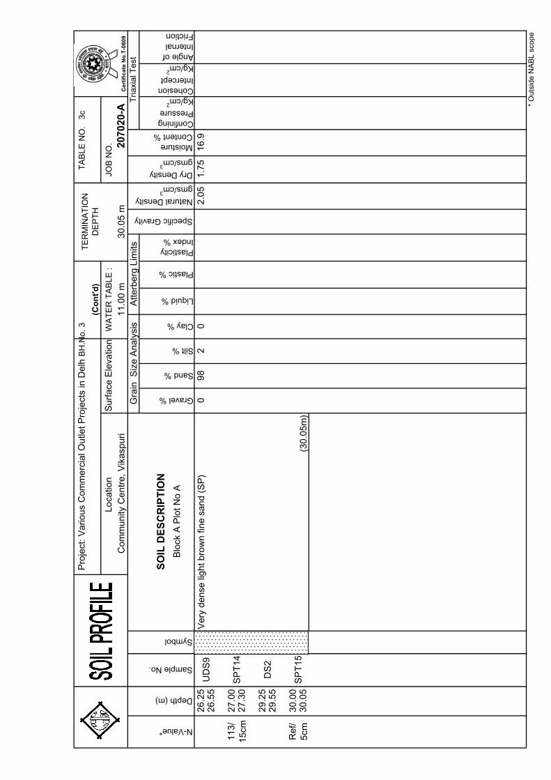
516.9
26.5
5
27.0
027.3
0
29.2
529.5
5
30.0
030.0
5R
ef/
5cm
SP
T15
DS
2
(30
.05
m)
113/
15
cmS
PT
14
UD
S9
Very
dense
light b
row
n fi
ne s
and (
SP
)
Natural Density
gms/cm3
Dry Density
gms/cm3
Moisture Content %
Tria
xia
l Te
st3
0.0
5 m
2070
20-A
N-Value*
Depth (m)
Sample No.
Symbol
SO
IL D
ES
CR
IPT
ION
Gra
in S
ize A
naly
sis
Atte
rberg
Lim
its
Specific Gravity
Surf
ace
Ele
vatio
nW
AT
ER
TA
BL
E :
(Co
nt'
d)
Co
mm
un
ity C
en
tre
, V
ika
spu
ri1
1.0
0 m
TE
RM
INA
TIO
N
DE
PT
H
* O
uts
ide
NA
BL
sco
pe
Loca
tion
Ce
rtif
ica
te N
o.T
-08
09
Blo
ck A
Plo
t N
o A
Pro
ject
: V
arious
Com
mer
cial
Outle
t P
roje
cts
in D
elh
BH
.No.
4
TA
BL
E N
O.
4
a
JO
B N
O.
Gravel %
Sand %
Silt %
Clay %
Liquid %
Plastic %
Plasticity Index %
Confining Pressure
Kg/cm2
Cohesion Intercept
Kg/cm2
Angle of Internal Friction
0.0
01.0
0
1.5
01.9
5
2.2
50
79
21
01.6
71.5
57.7
2.5
5
3.0
03.4
5
4.5
04.9
5
5.2
50
76
24
01.7
01.5
78.3
0.5
0.0
034o
5.5
51.0
1.5
6.0
0(D
S)
6.4
5
7.5
07.9
5
8.2
528.7
20.2
8.5
1.7
71.6
010.6
00.8
48.5
5(U
C)
9.0
09.4
5D
S : D
rain
ed D
irect
Shear
Test
10.5
0U
C :
Un
con
fine
d C
om
pre
ssio
n T
est
10.9
5
(Cont'd
on T
able
No.4
b)
* O
uts
ide
NA
BL
sco
pe
38
SP
T7
Dense
gre
y fin
e s
and (
SP
-SM
)
(7.5
m)
Dense
light g
rey
sandy
silt,
low
pla
stic
(C
L)
104
SP
T6
SP
T2
(10
.5m
)
36
SP
T5
UD
S3
SP
T4
UD
S2
24
SP
T3
31
Tria
xia
l Te
st
DS
1
N-Value*
Depth (m)
Sample No.
Symbol
Natural Density
gms/cm3
Dry Density
gms/cm3
Atterb
erg
Lim
its
Moisture Content %
14
SP
T1
37
UD
S1
2070
20-A
SO
IL D
ES
CR
IPT
ION
Mediu
m d
ense
light bro
wn s
ilty
fine s
and (
SM
)
TE
RM
INA
TIO
N
DE
PT
H
WA
TE
R T
AB
LE
:
Specific Gravity
Co
mm
un
ity C
en
tre
, V
ika
spu
ri3
0.4
5 m
10
.20
m
Surf
ace
Ele
vatio
nLoca
tion
Gra
in S
ize
Ana
lysi
sC
ert
ific
ate
No
.T-0
80
9
Blo
ck A
Plo
t N
o A
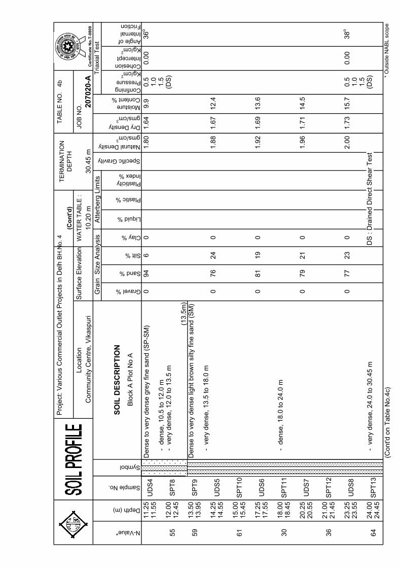
Pro
ject
: V
arious
Com
mer
cial
Outle
t P
roje
cts
in D
elh
BH
.No.
4
TA
BL
E N
O.
4
b
JO
B N
O.
Gravel %
Sand %
Silt %
Clay %
Liquid %
Plastic %
Plasticity Index %
Confining Pressure
Kg/cm2
Cohesion Intercept
Kg/cm2
Angle of Internal Friction
11.2
50
94
60
1.8
01.6
49.9
0.5
0.0
036o
11.5
51.0
1.5
12.0
0(D
S)
12.4
5
13.5
013.9
5
14.2
50
76
24
01.8
81.6
712.4
14.5
5
15.0
015.4
5
17.2
50
81
19
01.9
21.6
913.6
17.5
5
18.0
018.4
5
20.2
50
79
21
01.9
61.7
114.5
20.5
5
21.0
021.4
5
23.2
50
77
23
02.0
01.7
315.7
0.5
0.0
038o
23.5
51.0
1.5
24.0
0D
S : D
rain
ed D
irect
Shear
Test
(DS
)24.4
5
(Cont'd
on T
able
No.4
c)
-
dense
, 10.5
to 1
2.0
m
(13
.5m
)
-
very
dense
, 13.5
to 1
8.0
m
-
very
dense
, 12.0
to 1
3.5
m
TE
RM
INA
TIO
N
DE
PT
H
Loca
tion
Surf
ace
Ele
vatio
nW
AT
ER
TA
BL
E :
(Co
nt'
d)
Symbol
Moisture Content %
10
.20
m3
0.4
5 m
2070
20-A
Dry Density
gms/cm3
Tria
xia
l Te
stG
rain
Siz
e A
naly
sis
Atte
rberg
Lim
its
Specific Gravity
Natural Density
gms/cm3
Dense
to v
ery
dense
gre
y fin
e s
and (
SP
-SM
)
Com
munity
Centr
e, V
ikasp
uri
SO
IL D
ES
CR
IPT
ION
N-Value*
Depth (m)
Sample No.
55
SP
T8
UD
S4
59
SP
T9
Dense
to v
ery
dense
light b
row
n s
ilty
fine s
and (
SM
)
UD
S5
61
SP
T10
30
SP
T11
UD
S6
-
dense
, 18.0
to 2
4.0
m
UD
S7
36
SP
T12
UD
S8
64
SP
T13
-
very
dense
, 24.0
to 3
0.4
5 m
* O
uts
ide
NA
BL
sco
pe
Ce
rtif
ica
te N
o.T
-08
09
Blo
ck A
Plo
t N
o A
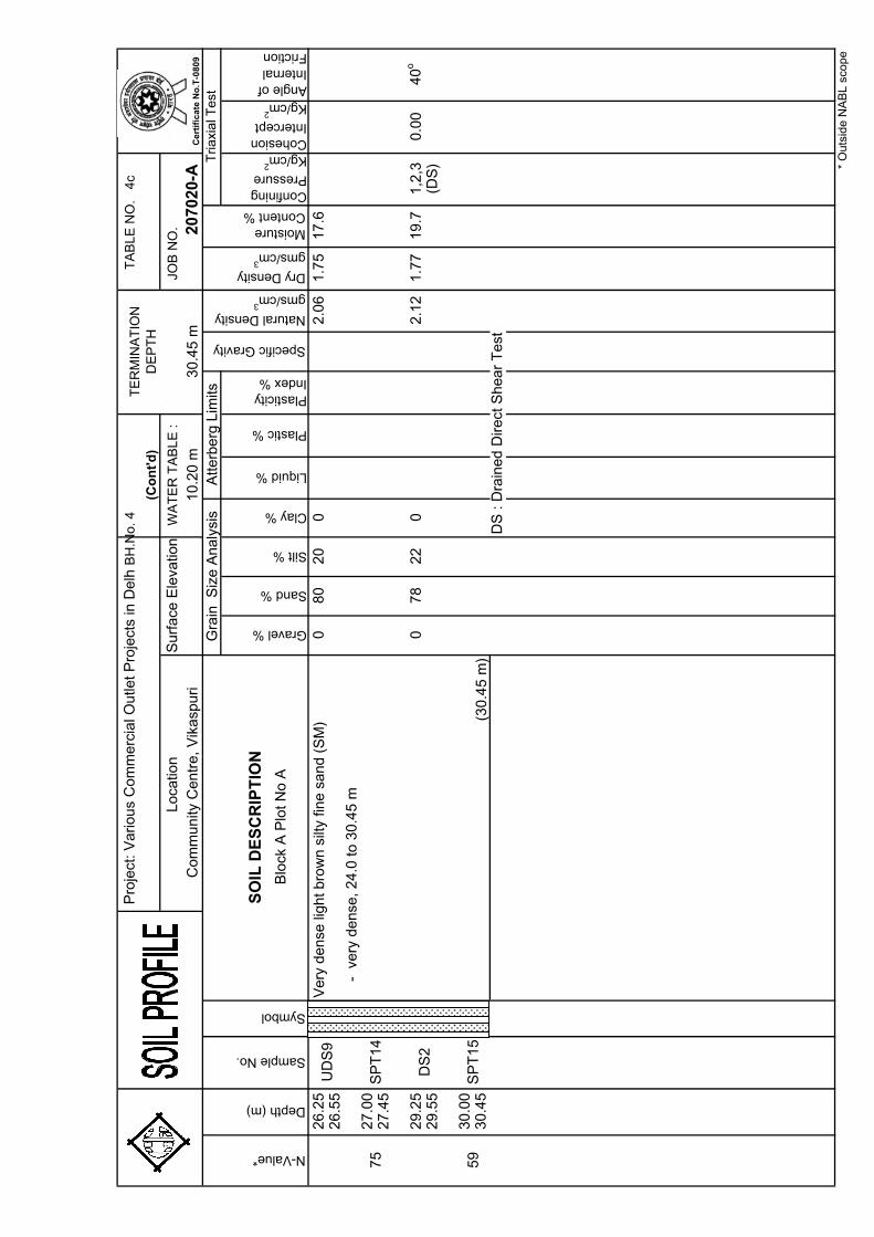
Pro
ject
: V
arious
Com
mer
cial
Outle
t P
roje
cts
in D
elh
BH
.No.
4
TA
BL
E N
O.
4
c
JO
B N
O.
Gravel %
Sand %
Silt %
Clay %
Liquid %
Plastic %
Plasticity Index %
Confining Pressure
Kg/cm2
Cohesion Intercept
Kg/cm2
Angle of Internal Friction
26.2
50
80
20
02.0
61.7
517.6
26.5
5
27.0
027.4
5
29.2
50
78
22
02.1
21.7
719.7
1,2
,30.0
040o
29.5
5(D
S)
30.0
030.4
5D
S : D
rain
ed D
irect
Shear
Test
* O
uts
ide
NA
BL
sco
pe
Loca
tion
TE
RM
INA
TIO
N
DE
PT
H
Surf
ace
Ele
vatio
nW
AT
ER
TA
BL
E :
(Co
nt'
d)
Co
mm
un
ity C
en
tre
, V
ika
spu
ri1
0.2
0 m
30
.45
m20
7020
-A
N-Value*
Depth (m)
Sample No.
Symbol
SO
IL D
ES
CR
IPT
ION
Gra
in S
ize A
naly
sis
Atte
rberg
Lim
its
Specific Gravity
Natural Density
gms/cm3
Dry Density
gms/cm3
Moisture Content %
Tria
xia
l Te
st
UD
S9
Very
dense
light b
row
n s
ilty
fine s
and (
SM
)
-
very
dense
, 24.0
to 3
0.4
5 m
75
SP
T14
59
SP
T15
DS
2
(30
.45
m)
Ce
rtif
ica
te N
o.T
-08
09
Blo
ck A
Plo
t N
o A
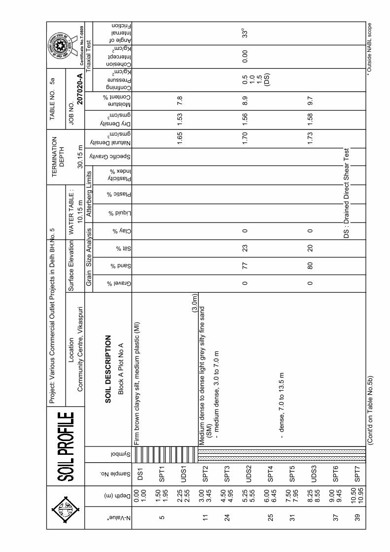
Pro
ject
: V
arious
Com
mer
cial
Outle
t P
roje
cts
in D
elh
BH
.No.
5
TA
BL
E N
O.
5
a
JO
B N
O.
Gravel %
Sand %
Silt %
Clay %
Liquid %
Plastic %
Plasticity Index %
Confining Pressure
Kg/cm2
Cohesion Intercept
Kg/cm2
Angle of Internal Friction
0.0
01.0
0
1.5
01.9
5
2.2
51.6
51.5
37.8
2.5
5
3.0
03.4
5
4.5
04.9
5
5.2
50
77
23
01.7
01.5
68.9
0.5
0.0
033o
5.5
51.0
1.5
6.0
0(D
S)
6.4
5
7.5
07.9
5
8.2
50
80
20
01.7
31.5
89.7
8.5
5
9.0
09.4
5D
S : D
rain
ed D
irect
Shear
Test
10.5
010.9
5
(Cont'd
on T
able
No.5
b)
(3.0
m)
Surf
ace
Ele
vatio
nLoca
tion
Gra
in S
ize
Ana
lysi
s
TE
RM
INA
TIO
N
DE
PT
H
WA
TE
R T
AB
LE
:
Specific Gravity
Co
mm
un
ity C
en
tre
, V
ika
spu
ri3
0.1
5 m
10
.15
m20
7020
-A
SO
IL D
ES
CR
IPT
ION
Firm
bro
wn c
laye
y si
lt, m
ediu
m p
last
ic (
MI)
5S
PT
1
11
UD
S1
Moisture Content %
Mediu
m d
ense
to d
ense
light g
rey
silty
fine s
and
(S
M)
Tria
xia
l Te
st
DS
1
N-Value*
Depth (m)
Sample No.
Symbol
Natural Density
gms/cm3
Dry Density
gms/cm3
Atterb
erg
Lim
its
UD
S2
24
SP
T3
25
37
SP
T6
SP
T2
31
SP
T5
UD
S3
SP
T4
- m
ed
ium
de
nse
, 3
.0 t
o 7
.0 m
-
dense
, 7.0
to 1
3.5
m
* O
uts
ide
NA
BL
sco
pe
39
SP
T7
Ce
rtif
ica
te N
o.T
-08
09
Blo
ck A
Plo
t N
o A
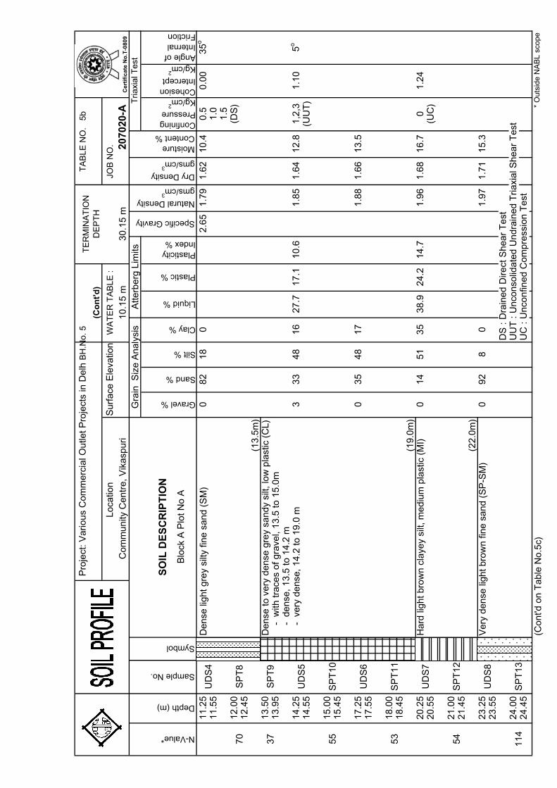
Pro
ject
: V
arious
Com
mer
cial
Outle
t P
roje
cts
in D
elh
BH
.No.
5
TA
BL
E N
O.
5
b
JO
B N
O.
Gravel %
Sand %
Silt %
Clay %
Liquid %
Plastic %
Plasticity Index %
Confining Pressure
Kg/cm2
Cohesion Intercept
Kg/cm2
Angle of Internal Friction
11.2
50
82
18
02.6
51.7
91.6
210.4
0.5
0.0
035o
11.5
51.0
1.5
12.0
0(D
S)
12.4
5
13.5
013.9
5
14.2
53
33
48
16
27.7
17.1
10.6
1.8
51.6
412.8
1,2
,31.1
05
o
14.5
5(U
UT
)
15.0
015.4
5
17.2
50
35
48
17
1.8
81.6
613.5
17.5
5
18.0
018.4
5
20.2
50
14
51
35
38.9
24.2
14.7
1.9
61.6
816.7
01.2
420.5
5(U
C)
21.0
021.4
5
23.2
50
92
80
1.9
71.7
115.3
23.5
5D
S : D
rain
ed D
irect
Shear
Test
24.0
0U
UT
: U
nco
nso
lidate
d U
ndra
ined T
riaxi
al S
hear
Test
24.4
5U
C :
Un
con
fine
d C
om
pre
ssio
n T
est
(Cont'd
on T
able
No.5
c)*
Ou
tsid
e N
AB
L s
cop
e
UD
S8
Very
dense
light b
row
n fi
ne s
and (
SP
-SM
)
114
SP
T13
54
SP
T12
UD
S7
Hard
light bro
wn c
laye
y si
lt, m
ediu
m p
last
ic (
MI)
55
SP
T10
53
SP
T11
UD
S6
UD
S5
-
very
dense
, 14.2
to 1
9.0
m
37
SP
T9
Dense
to v
ery
dense
gre
y sa
ndy
silt,
low
pla
stic
(C
L)
-
with
tra
ces
of gra
vel,
13.5
to 1
5.0
m
N-Value*
Depth (m)
Sample No.
70
SP
T8
UD
S4
Dense
light g
rey
silty
fine s
and (
SM
)
Com
munity
Centr
e, V
ikasp
uri
SO
IL D
ES
CR
IPT
ION
Moisture Content %
10
.15
m3
0.1
5 m
2070
20-A
Dry Density
gms/cm3
Tria
xia
l Te
stG
rain
Siz
e A
naly
sis
Atte
rberg
Lim
its
Specific Gravity
Natural Density
gms/cm3
Symbol
(19
.0m
)
TE
RM
INA
TIO
N
DE
PT
H
Loca
tion
Surf
ace
Ele
vatio
nW
AT
ER
TA
BL
E :
(Co
nt'
d)
(13
.5m
)
-
dense
, 13.5
to 1
4.2
m
(22
.0m
)
Ce
rtif
ica
te N
o.T
-08
09
Blo
ck A
Plo
t N
o A
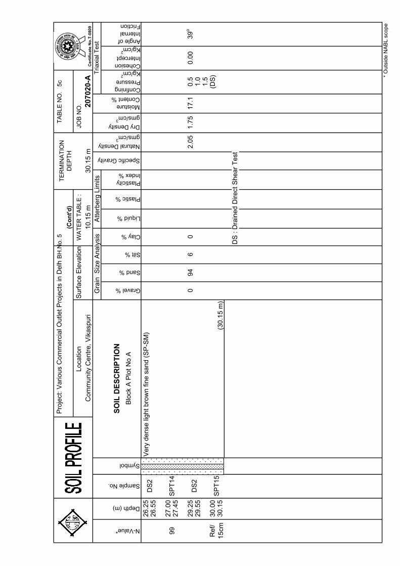
Pro
ject
: V
arious
Com
mer
cial
Outle
t P
roje
cts
in D
elh
BH
.No.
5
TA
BL
E N
O.
5
c
JO
B N
O.
Gravel %
Sand %
Silt %
Clay %
Liquid %
Plastic %
Plasticity Index %
Confining Pressure
Kg/cm2
Cohesion Intercept
Kg/cm2
Angle of Internal Friction
26.2
526.5
5
27.0
027.4
5
29.2
50
94
60
2.0
51.7
517.1
0.5
0.0
039o
29.5
51.0
1.5
30.0
0(D
S)
30.1
5
DS
: D
rain
ed D
irect
Shear
Test
Ref/
15
cmS
PT
15
DS
2
(30
.15
m)
99
SP
T14
DS
2V
ery
dense
light b
row
n fi
ne s
and (
SP
-SM
)
Natural Density
gms/cm3
Dry Density
gms/cm3
Moisture Content %
Tria
xia
l Te
st3
0.1
5 m
2070
20-A
N-Value*
Depth (m)
Sample No.
Symbol
SO
IL D
ES
CR
IPT
ION
Gra
in S
ize A
naly
sis
Atte
rberg
Lim
its
Specific Gravity
Surf
ace
Ele
vatio
nW
AT
ER
TA
BL
E :
(Co
nt'
d)
Co
mm
un
ity C
en
tre
, V
ika
spu
ri1
0.1
5 m
TE
RM
INA
TIO
N
DE
PT
H
* O
uts
ide
NA
BL
sco
pe
Loca
tion
Ce
rtif
ica
te N
o.T
-08
09
Blo
ck A
Plo
t N
o A
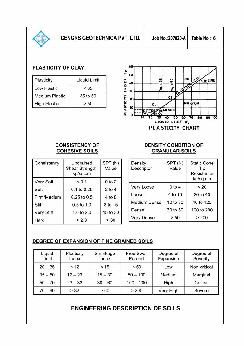
CENGRS GEOTECHNICA PVT. LTD. Job No.:207020-A Table No.: 6
PLASTICITY OF CLAY
Plasticity Liquid Limit
Low Plastic < 35 Medium Plastic 35 to 50 High Plastic > 50
CONSISTENCY OF COHESIVE SOILS
Consistency Undrained Shear Strength,
kg/sq.cm
SPT (N) Value
Very Soft < 0.1 0 to 2 Soft 0.1 to 0.25 2 to 4 Firm/Medium 0.25 to 0.5 4 to 8 Stiff 0.5 to 1.0 8 to 15 Very Stiff 1.0 to 2.0 15 to 30 Hard > 2.0 > 30
DENSITY CONDITION OF GRANULAR SOILS
Density Descriptor
SPT (N) Value
Static Cone Tip
Resistance kg/sq.cm
Very Loose 0 to 4 < 20 Loose 4 to 10 20 to 40 Medium Dense 10 to 30 40 to 120 Dense 30 to 50 120 to 200 Very Dense > 50 > 200
DEGREE OF EXPANSION OF FINE GRAINED SOILS
Liquid Limit
Plasticity Index
Shrinkage Index
Free Swell Percent
Degree of Expansion
Degree of Severity
20 – 35 < 12 < 15 < 50 Low Non-critical
35 – 50 12 – 23 15 – 30 50 – 100 Medium Marginal
50 – 70 23 – 32 30 – 60 100 – 200 High Critical
70 – 90 > 32 > 60 > 200 Very High Severe
ENGINEERING DESCRIPTION OF SOILS
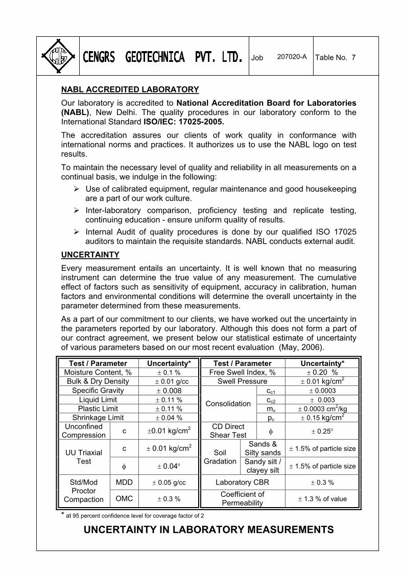
NABL ACCREDITED LABORATORY
207020-A Table No. 7 Job
Our laboratory is accredited to National Accreditation Board for Laboratories (NABL), New Delhi. The quality procedures in our laboratory conform to the International Standard ISO/IEC: 17025-2005.
The accreditation assures our clients of work quality in conformance with international norms and practices. It authorizes us to use the NABL logo on test results.
To maintain the necessary level of quality and reliability in all measurements on a continual basis, we indulge in the following:
Use of calibrated equipment, regular maintenance and good housekeeping are a part of our work culture.
Inter-laboratory comparison, proficiency testing and replicate testing, continuing education - ensure uniform quality of results.
Internal Audit of quality procedures is done by our qualified ISO 17025 auditors to maintain the requisite standards. NABL conducts external audit.
UNCERTAINTY
Every measurement entails an uncertainty. It is well known that no measuring instrument can determine the true value of any measurement. The cumulative effect of factors such as sensitivity of equipment, accuracy in calibration, human factors and environmental conditions will determine the overall uncertainty in the parameter determined from these measurements.
As a part of our commitment to our clients, we have worked out the uncertainty in the parameters reported by our laboratory. Although this does not form a part of our contract agreement, we present below our statistical estimate of uncertainty of various parameters based on our most recent evaluation (May, 2006).
Test / Parameter Uncertainty* Test / Parameter Uncertainty* Moisture Content, % ± 0.1 % Free Swell Index, % ± 0.20 % Bulk & Dry Density ± 0.01 g/cc Swell Pressure ± 0.01 kg/cm2
Specific Gravity ± 0.008 cc1 ± 0.0003 Liquid Limit ± 0.11 % cc2 ± 0.003 Plastic Limit ± 0.11 % mv ± 0.0003 cm2/kg
Shrinkage Limit ± 0.04 %
Consolidation
pc ± 0.15 kg/cm2 Unconfined
Compression c ±0.01 kg/cm2
CD Direct Shear Test φ ± 0.25°
c ± 0.01 kg/cm2 Sands &
Silty sands ± 1.5% of particle size
UU Triaxial Test
φ ± 0.04°
Soil Gradation Sandy silt /
clayey silt ± 1.5% of particle size
MDD ± 0.05 g/cc Laboratory CBR ± 0.3 % Std/Mod Proctor
Compaction OMC ± 0.3 % Coefficient of Permeability
± 1.3 % of value
* at 95 percent confidence level for coverage factor of 2
UNCERTAINTY IN LABORATORY MEASUREMENTS
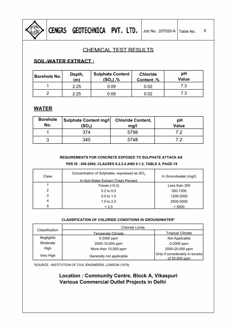
8
Borehole No.pH
Value
1 7.3
2 7.3
WATER
Borehole No.
1
3
1
2
3
4
5
Negligible
Moderate
High
Very High
374 5798 7.2
340 5748 7.2
PER IS : 456-2000, CLAUSES 8.2.2.4 AND 9.1.2, TABLE 4, PAGE-19
REQUIREMENTS FOR CONCRETE EXPOSED TO SULPHATE ATTACK AS
Location : Community Centre, Block A, VikaspuriVarious Commercial Outlet Projects in Delhi
Class In Groundwater (mg/l)
Less than 300
Concentration of Sulphates, expressed as SO3
In-Soil-Water Extract (Total) PercentTraces (<0.2)
0.2 to 0.5
> 2.0
300-1200
CHEMICAL TEST RESULTS
SOIL-WATER EXTRACT :
Depth, (m)
Sulphate Content (SO3) ,%
Chloride Content ,%
2000-10,000 ppm 0-2000 ppm
*SOURCE : INSTITUTION OF CIVIL ENGINEERS, LONDON (1979)
More than 10,000 ppm 2000-20,000 ppm
Generally not applicableOnly if considerably in excess
of 20,000 ppm
0-2000 ppm Not Applicable
ClassificationTropical ClimateTemperate Climate
Chloride Limits
CLASSIFICATION OF CHLORIDE CONDITIONS IN GROUNDWATER*
> 5000
1200-2500
1.0 to 2.0 2500-5000
0.5 to 1.0
2.25 0.09 0.02
0.022.25
Sulphate Content mg/l (SO3)
Chloride Content, mg/l
0.09
pH Value
Job No. Table No.207020-A
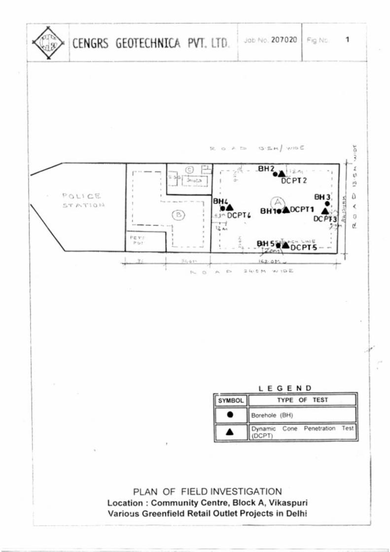
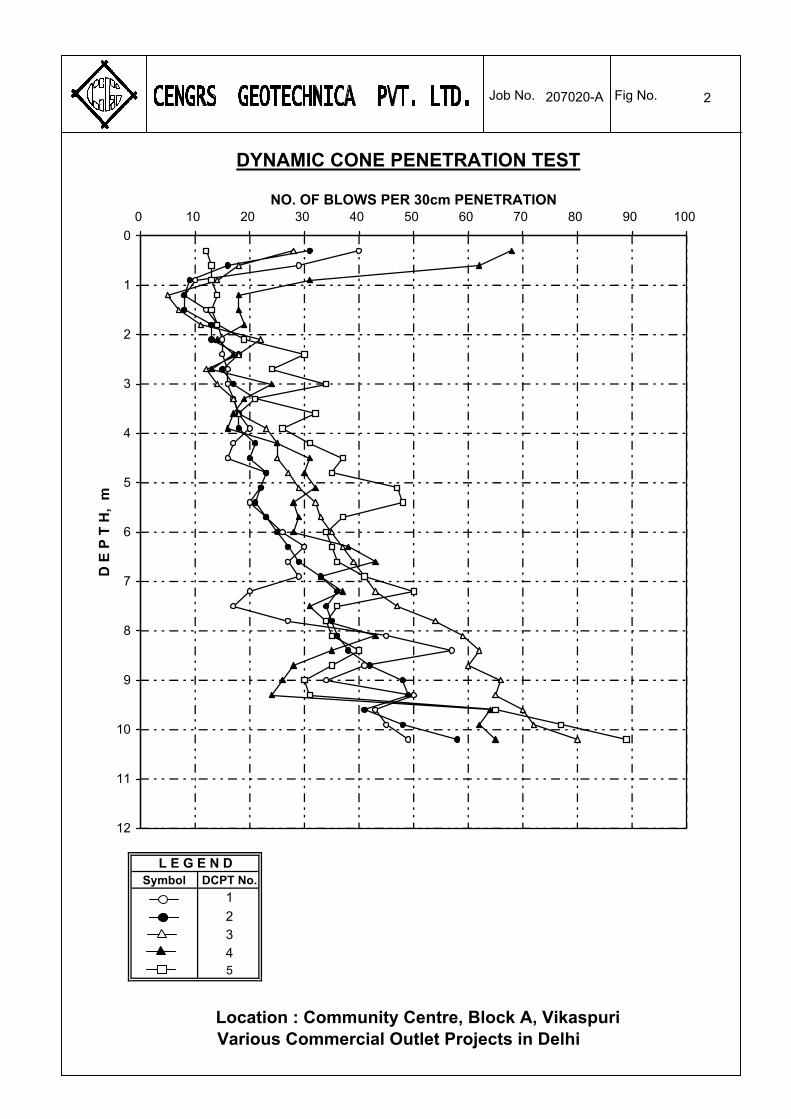
2
Symbol DCPT No.
1
2345
L E G E N D
DYNAMIC CONE PENETRATION TEST
0
1
2
3
4
5
6
7
8
9
10
11
12
0 10 20 30 40 50 60 70 80 90 100NO. OF BLOWS PER 30cm PENETRATION
D E
P T
H,
m Job No. Fig No.
Location : Community Centre, Block A, VikaspuriVarious Commercial Outlet Projects in Delhi
207020-A
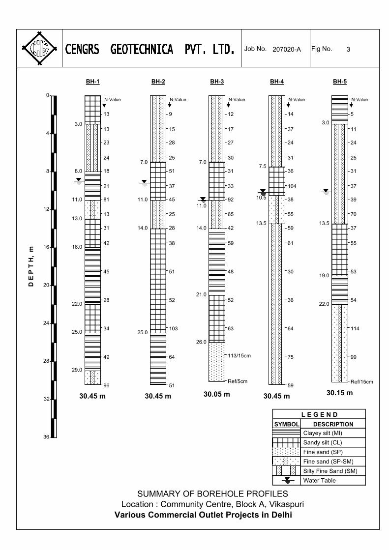
SYMBOL
Clayey silt (MI)
Sandy silt (CL)
Fine sand (SP)
Fine sand (SP-SM)
Silty Fine Sand (SM)
Water Table
L E G E N D
DESCRIPTION
4
8
12
16
20
24
28
D E
P T
H,
m
32
36
Job No. Fig No.207020-A
0
SUMMARY OF BOREHOLE PROFILESLocation : Community Centre, Block A, Vikaspuri
Various Commercial Outlet Projects in Delhi
15
28
25
51
37
45
28
25
38
51
52
9
103
64
51
N-Value
BH-2
30.45 m
11.0
7.0
14.0
25.0
17
27
30
31
33
92
42
65
59
48
52
12
63
113/15cm
Ref/5cm
N-Value
BH-3
30.05 m
11.0
7.0
14.0
26.0
21.0
37
24
31
36
104
38
59
55
61
30
36
14
64
75
59
N-Value
BH-4
30.45 m
7.5
10.5
13.5
11
24
25
31
37
39
37
70
55
53
54
5
114
99
Ref/15cm
N-Value
BH-5
30.15 m
13.5
3.0
19.0
22.0
13
23
24
18
21
81
31
13
42
45
28
13
34
49
96
N-Value
BH-1
30.45 m
8.0
11.0
22.0
3.0
16.0
29.0
25.0
13.0
3
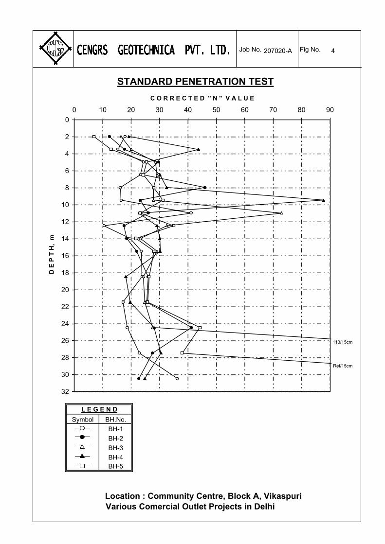
C
4
Symbol BH.No.
BH-1
BH-2
BH-3
BH-4BH-5
L E G E N D
Job No. Fig No.
STANDARD PENETRATION TEST
0
2
4
6
8
10
12
14
16
18
20
22
24
26
28
30
32
0 10 20 30 40 50 60 70 80 90
C O R R E C T E D " N " V A L U E
D E
P T
H,
m
Location : Community Centre, Block A, VikaspuriVarious Comercial Outlet Projects in Delhi
207020-A
113/15cm
Ref/15cm

5
SYMBOL BORE DEPTH DESCRIPTION GRAVEL SAND SILT CLAY D60 D10 Cu
HOLE m % % % %
GRAIN SIZE ANALYSIS
Sandy silt with gravel (CL)
Silty fine sand (SM)
Clayey silt (MI)
Fine sand (SP-SM)
1 2.25 9 40
Location : Community Centre, Block A, VikaspuriVarious Commercial Outlet Projects in Delhi
41 10 0.140
1 5.25 0 77 23 0 0.240
1 8.25 0 14 51 35 0.013
1 11.25 0 92 8 0 0.280 0.094 2.98
0
10
20
30
40
50
60
70
80
90
100
0.001 0.01 0.1 1 10P A R T I C L E S I Z E , m m
PE
RC
EN
T F
INE
R B
Y W
EIG
HT
GRAVELFINE MEDIUMS I L T COARSE
S A N DCLAY
207020-A Job No. Fig No.
Certificate No.T-0809
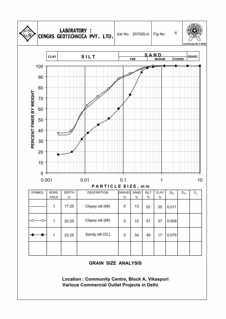
6
SYMBOL BORE DEPTH DESCRIPTION GRAVEL SAND SILT CLAY D60 D10 Cu
HOLE m % % % %
GRAIN SIZE ANALYSIS
Clayey silt (MI)
Clayey silt (MI)
Sandy silt (CL)
1 17.25 0 13
Location : Community Centre, Block A, VikaspuriVarious Commercial Outlet Projects in Delhi
52 35 0.011
1 20.25 0 12 51 37 0.009
1 23.25 0 34 49 17 0.075
0
10
20
30
40
50
60
70
80
90
100
0.001 0.01 0.1 1 10P A R T I C L E S I Z E , m m
PE
RC
EN
T F
INE
R B
Y W
EIG
HT
GRAVELFINE MEDIUMS I L T COARSE
S A N DCLAY
207020-A Job No. Fig No.
Certificate No.T-0809
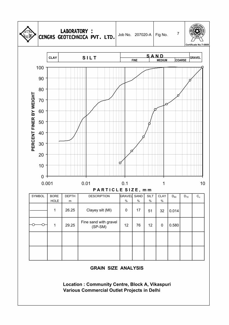
7
SYMBOL BORE DEPTH DESCRIPTION GRAVEL SAND SILT CLAY D60 D10 Cu
HOLE m % % % %
GRAIN SIZE ANALYSIS
Clayey silt (MI)
Fine sand with gravel (SP-SM)
1 26.25 0 17
Location : Community Centre, Block A, VikaspuriVarious Commercial Outlet Projects in Delhi
51 32 0.014
1 29.25 12 76 12 0 0.580
0
10
20
30
40
50
60
70
80
90
100
0.001 0.01 0.1 1 10P A R T I C L E S I Z E , m m
PE
RC
EN
T F
INE
R B
Y W
EIG
HT
GRAVELFINE MEDIUMS I L T COARSE
S A N DCLAY
207020-A Job No. Fig No.
Certificate No.T-0809
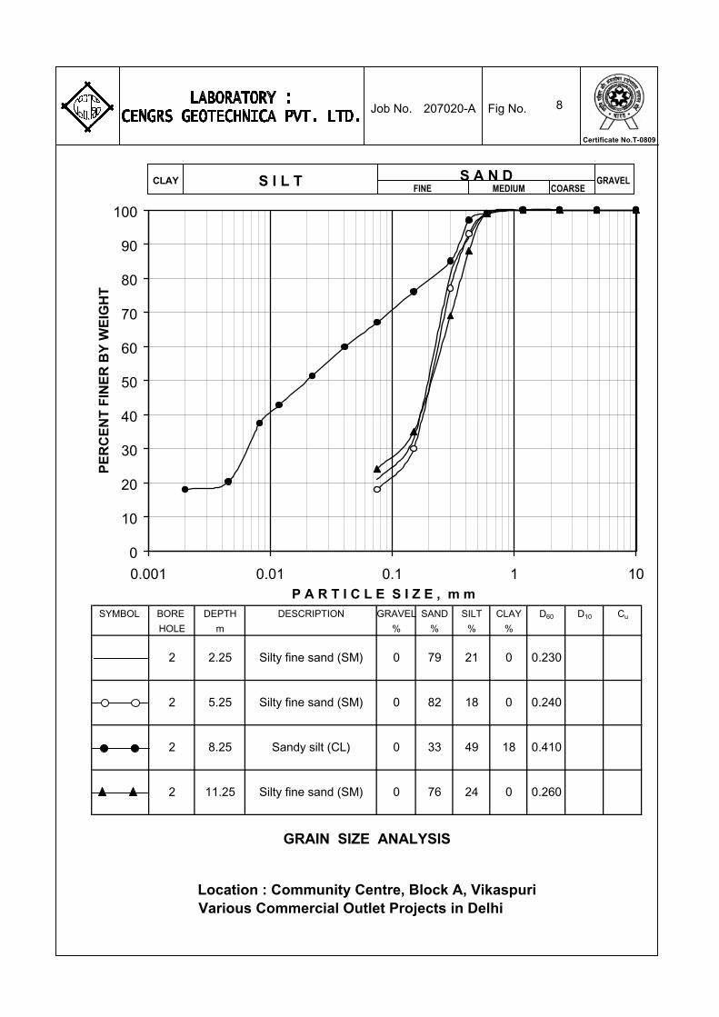
8
SYMBOL BORE DEPTH DESCRIPTION GRAVEL SAND SILT CLAY D60 D10 Cu
HOLE m % % % %
2 11.25 0 76 24 0 0.260
49 18 0.4102 8.25 0 33
2 5.25 0 82 18 0 0.240
21 0 0.230
GRAIN SIZE ANALYSIS
Silty fine sand (SM)
Silty fine sand (SM)
Sandy silt (CL)
Silty fine sand (SM)
2 2.25 0 79
Location : Community Centre, Block A, VikaspuriVarious Commercial Outlet Projects in Delhi
0
10
20
30
40
50
60
70
80
90
100
0.001 0.01 0.1 1 10P A R T I C L E S I Z E , m m
PE
RC
EN
T F
INE
R B
Y W
EIG
HT
GRAVELFINE MEDIUMS I L T COARSE
S A N DCLAY
207020-A Job No. Fig No.
Certificate No.T-0809
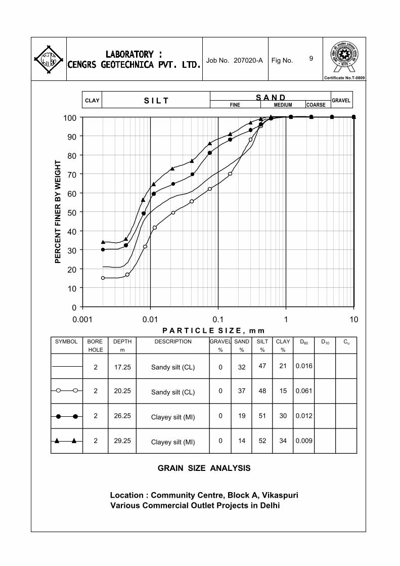
9
SYMBOL BORE DEPTH DESCRIPTION GRAVEL SAND SILT CLAY D60 D10 Cu
HOLE m % % % %
2 29.25 0 14 52 34 0.009
51 30 0.0122 26.25 0 19
2 20.25 0 37 48 15 0.061
47 21 0.016
Location : Community Centre, Block A, VikaspuriVarious Commercial Outlet Projects in Delhi
GRAIN SIZE ANALYSIS
Sandy silt (CL)
Sandy silt (CL)
Clayey silt (MI)
Clayey silt (MI)
2 17.25 0 32
0
10
20
30
40
50
60
70
80
90
100
0.001 0.01 0.1 1 10P A R T I C L E S I Z E , m m
PE
RC
EN
T F
INE
R B
Y W
EIG
HT
GRAVELFINE MEDIUMS I L T COARSE
S A N DCLAY
207020-A Job No. Fig No.
Certificate No.T-0809
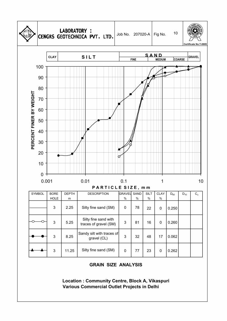
10
SYMBOL BORE DEPTH DESCRIPTION GRAVEL SAND SILT CLAY D60 D10 Cu
HOLE m % % % %
GRAIN SIZE ANALYSIS
Silty fine sand (SM)
Silty fine sand with traces of gravel (SM)
Sandy silt with traces of gravel (CL)
Silty fine sand (SM)
3 2.25 0 78
Location : Community Centre, Block A, VikaspuriVarious Commercial Outlet Projects in Delhi
22 0 0.250
3 5.25 3 81 16 0 0.260
3 8.25 3 32 48 17 0.062
3 11.25 0 77 23 0 0.262
0
10
20
30
40
50
60
70
80
90
100
0.001 0.01 0.1 1 10P A R T I C L E S I Z E , m m
PE
RC
EN
T F
INE
R B
Y W
EIG
HT
GRAVELFINE MEDIUMS I L T COARSE
S A N DCLAY
207020-A Job No. Fig No.
Certificate No.T-0809
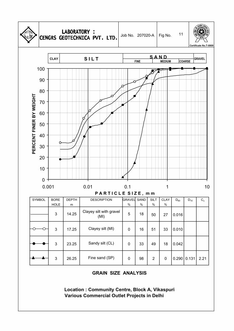
11
SYMBOL BORE DEPTH DESCRIPTION GRAVEL SAND SILT CLAY D60 D10 Cu
HOLE m % % % %
GRAIN SIZE ANALYSIS
Clayey silt with gravel (MI)
Clayey silt (MI)
Sandy silt (CL)
Fine sand (SP)
3 14.25 5 18
Location : Community Centre, Block A, VikaspuriVarious Commercial Outlet Projects in Delhi
50 27 0.016
3 17.25 0 16 51 33 0.010
3 23.25 0 33 49 18 0.042
3 26.25 0 98 2 0 0.290 0.131 2.21
0
10
20
30
40
50
60
70
80
90
100
0.001 0.01 0.1 1 10P A R T I C L E S I Z E , m m
PE
RC
EN
T F
INE
R B
Y W
EIG
HT
GRAVELFINE MEDIUMS I L T COARSE
S A N DCLAY
207020-A Job No. Fig No.
Certificate No.T-0809
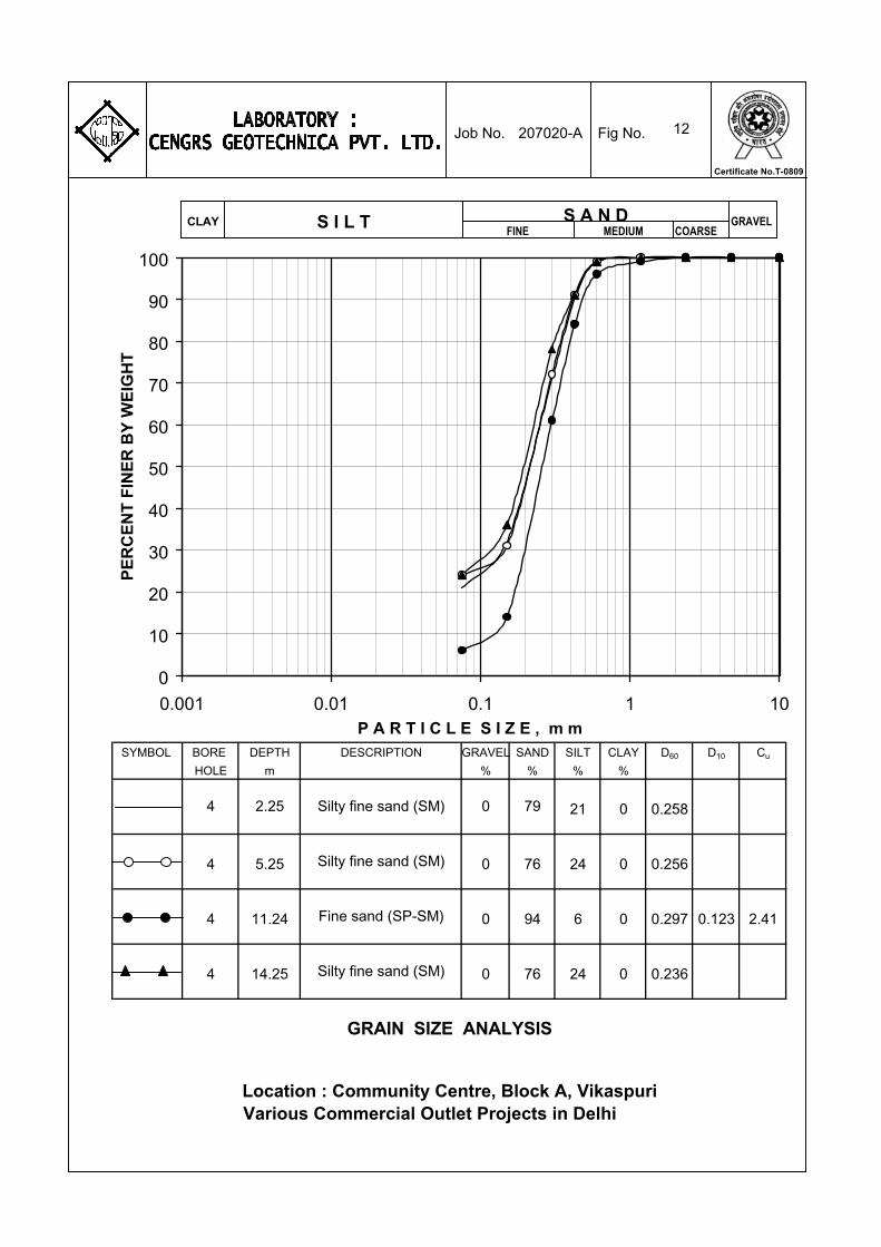
12
SYMBOL BORE DEPTH DESCRIPTION GRAVEL SAND SILT CLAY D60 D10 Cu
HOLE m % % % %
GRAIN SIZE ANALYSIS
Silty fine sand (SM)
Silty fine sand (SM)
Fine sand (SP-SM)
Silty fine sand (SM)
4 2.25 0 79
Location : Community Centre, Block A, VikaspuriVarious Commercial Outlet Projects in Delhi
21 0 0.258
4 5.25 0 76 24 0 0.256
4 11.24 0 94 6 0 0.297 0.123 2.41
4 14.25 0 76 24 0 0.236
0
10
20
30
40
50
60
70
80
90
100
0.001 0.01 0.1 1 10P A R T I C L E S I Z E , m m
PE
RC
EN
T F
INE
R B
Y W
EIG
HT
GRAVELFINE MEDIUMS I L T COARSE
S A N DCLAY
207020-A Job No. Fig No.
Certificate No.T-0809

13
SYMBOL BORE DEPTH DESCRIPTION GRAVEL SAND SILT CLAY D60 D10 Cu
HOLE m % % % %
23 0 0.2464 23.25 0 77
4 20.25 0 79 21 0 0.272
19 0 0.258
GRAIN SIZE ANALYSIS
Silty fine sand (SM)
Silty fine sand (SM)
Silty fine sand (SM)
4 17.25 0 81
Location : Community Centre, Block A, VikaspuriVarious Commercial Outlet Projects in Delhi
0
10
20
30
40
50
60
70
80
90
100
0.001 0.01 0.1 1 10P A R T I C L E S I Z E , m m
PE
RC
EN
T F
INE
R B
Y W
EIG
HT
GRAVELFINE MEDIUMS I L T COARSE
S A N DCLAY
207020-A Job No. Fig No.
Certificate No.T-0809
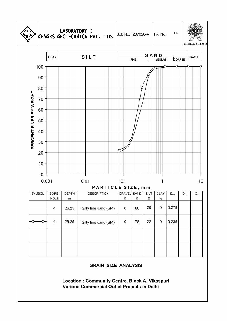
14
SYMBOL BORE DEPTH DESCRIPTION GRAVEL SAND SILT CLAY D60 D10 Cu
HOLE m % % % %
4 29.25 0 78 22 0 0.239
20 0 0.279
Location : Community Centre, Block A, VikaspuriVarious Commercial Outlet Projects in Delhi
GRAIN SIZE ANALYSIS
Silty fine sand (SM)
Silty fine sand (SM)
4 26.25 0 80
0
10
20
30
40
50
60
70
80
90
100
0.001 0.01 0.1 1 10P A R T I C L E S I Z E , m m
PE
RC
EN
T F
INE
R B
Y W
EIG
HT
GRAVELFINE MEDIUMS I L T COARSE
S A N DCLAY
207020-A Job No. Fig No.
Certificate No.T-0809

15
SYMBOL BORE DEPTH DESCRIPTION GRAVEL SAND SILT CLAY D60 D10 Cu
HOLE m % % % %
GRAIN SIZE ANALYSIS
Silty fine sand (SM)
Silty fine sand (SM)
Silty fine sand (SM)
Sandy silt with traces of gravel (CL)
5 5.25 0 77
Location : Community Centre, Block A, VikaspuriVarious Commercial Outlet Projects in Delhi
23 0 0.264
5 8.25 0 80 20 0 0.255
5 11.25 0 82 18 0 0.256
5 14.25 3 33 48 16 0.056
0
10
20
30
40
50
60
70
80
90
100
0.001 0.01 0.1 1 10P A R T I C L E S I Z E , m m
PE
RC
EN
T F
INE
R B
Y W
EIG
HT
GRAVELFINE MEDIUMS I L T COARSE
S A N DCLAY
207020-A Job No. Fig No.
Certificate No.T-0809
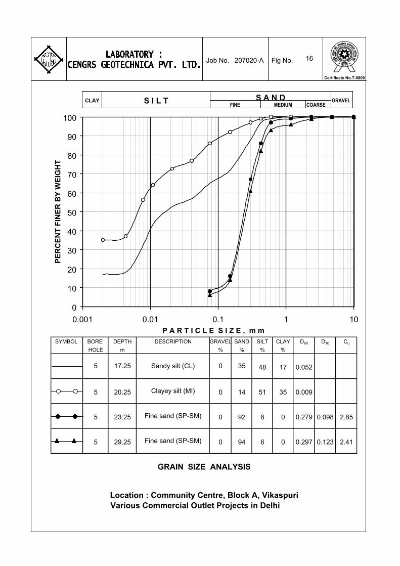
16
SYMBOL BORE DEPTH DESCRIPTION GRAVEL SAND SILT CLAY D60 D10 Cu
HOLE m % % % %
GRAIN SIZE ANALYSIS
Sandy silt (CL)
Clayey silt (MI)
Fine sand (SP-SM)
Fine sand (SP-SM)
5 17.25 0 35
Location : Community Centre, Block A, VikaspuriVarious Commercial Outlet Projects in Delhi
48 17 0.052
5 20.25 0 14 51 35 0.009
5 23.25 0 92 8 0 0.279 0.098 2.85
5 29.25 0 94 6 0 0.297 0.123 2.41
0
10
20
30
40
50
60
70
80
90
100
0.001 0.01 0.1 1 10P A R T I C L E S I Z E , m m
PE
RC
EN
T F
INE
R B
Y W
EIG
HT
GRAVELFINE MEDIUMS I L T COARSE
S A N DCLAY
207020-A Job No. Fig No.
Certificate No.T-0809

Borehole No : 1 Dry Density "c" Value "Φ" ValueDepth : 5.25 m gm/cc kg/cm2
DEGREE
1.56 0 32
Type of Test : Saturated Consolidated Drained Type of Soil : Silty Fine Sand
D R A I N E D D I R E C T S H E A R T E S T
Location : Community Centre,Block-A,VikaspuriVarious Commercial Outlet Projects in Delhi
0.0
0.5
1.0
1.5
2.0
2.5
0 0.5 1 1.5 2 2.5 3 3.5
N O R M A L S T R E S S ( kg/cm2 )
S H
E A
R S
T R
E S
S (
kg/c
m2 )
Job No. 207020-A Fig No. 17
Certificate No.T-0809
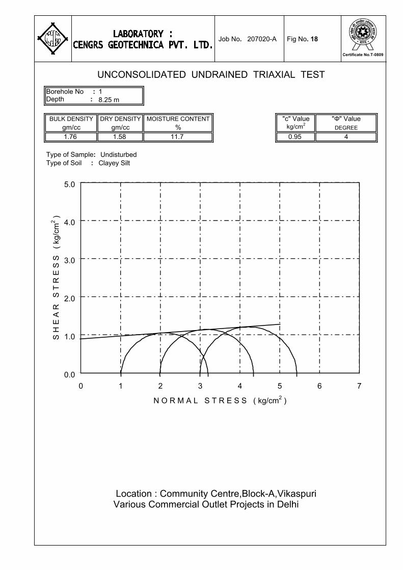
Borehole No : 1Depth : 8.25 m
BULK DENSITY DRY DENSITY MOISTURE CONTENT "c" Value "Φ" Valuegm/cc gm/cc % kg/cm2
DEGREE
1.76 1.58 11.7 0.95 4
Type of Sample: UndisturbedType of Soil : Clayey Silt
Various Commercial Outlet Projects in Delhi
UNCONSOLIDATED UNDRAINED TRIAXIAL TEST
Location : Community Centre,Block-A,Vikaspuri
0.0
1.0
2.0
3.0
4.0
5.0
0 1 2 3 4 5 6 7
N O R M A L S T R E S S ( kg/cm2 )
S H
E A
R
S T
R E
S S
(
kg
/cm
2 )
Job No. 207020-A Fig No. 18
Certificate No.T-0809

Borehole No : 2 Dry Density "c" Value "Φ" ValueDepth : 2.25 m gm/cc kg/cm2
DEGREE
1.53 0 30
Type of Test : Saturated Consolidated Drained Type of Soil : Silty Fine Sand
D R A I N E D D I R E C T S H E A R T E S T
Location : Community Centre,Block-A,VikaspuriVarious Commercial Outlet Projects in Delhi
0.0
0.5
1.0
1.5
2.0
2.5
0 0.5 1 1.5 2 2.5 3 3.5
N O R M A L S T R E S S ( kg/cm2 )
S H
E A
R S
T R
E S
S (
kg/c
m2 )
Job No. 207020-A Fig No. 19
Certificate No.T-0809
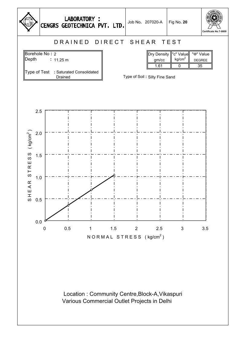
Borehole No : 2 Dry Density "c" Value "Φ" ValueDepth : 11.25 m gm/cc kg/cm2
DEGREE
1.61 0 35
Type of Test : Saturated Consolidated Drained Type of Soil : Silty Fine Sand
D R A I N E D D I R E C T S H E A R T E S T
Location : Community Centre,Block-A,VikaspuriVarious Commercial Outlet Projects in Delhi
0.0
0.5
1.0
1.5
2.0
2.5
0 0.5 1 1.5 2 2.5 3 3.5
N O R M A L S T R E S S ( kg/cm2 )
S H
E A
R S
T R
E S
S (
kg/c
m2 )
Job No. 207020-A Fig No. 20
Certificate No.T-0809
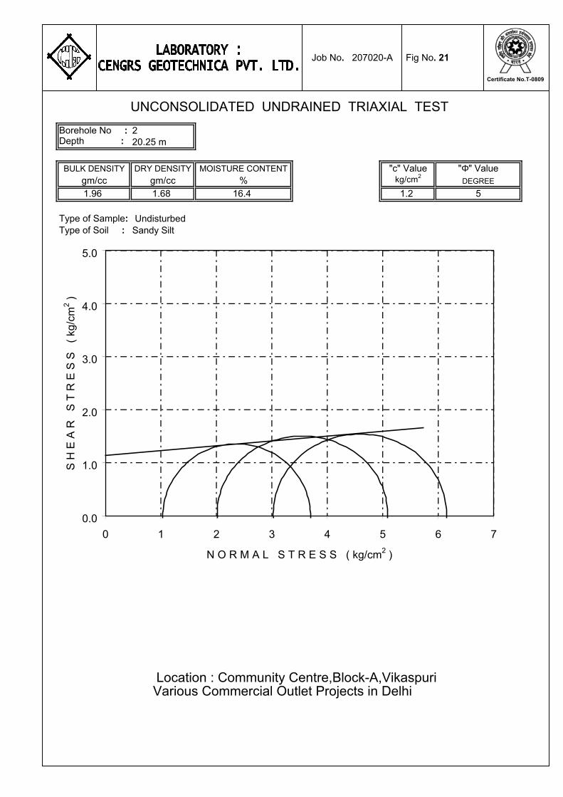
Borehole No : 2Depth : 20.25 m
BULK DENSITY DRY DENSITY MOISTURE CONTENT "c" Value "Φ" Valuegm/cc gm/cc % kg/cm2
DEGREE
1.96 1.68 16.4 1.2 5
Type of Sample: UndisturbedType of Soil : Sandy Silt
Various Commercial Outlet Projects in Delhi
UNCONSOLIDATED UNDRAINED TRIAXIAL TEST
Location : Community Centre,Block-A,Vikaspuri
0.0
1.0
2.0
3.0
4.0
5.0
0 1 2 3 4 5 6 7
N O R M A L S T R E S S ( kg/cm2 )
S H
E A
R
S T
R E
S S
(
kg
/cm
2 )
Job No. 207020-A Fig No. 21
Certificate No.T-0809
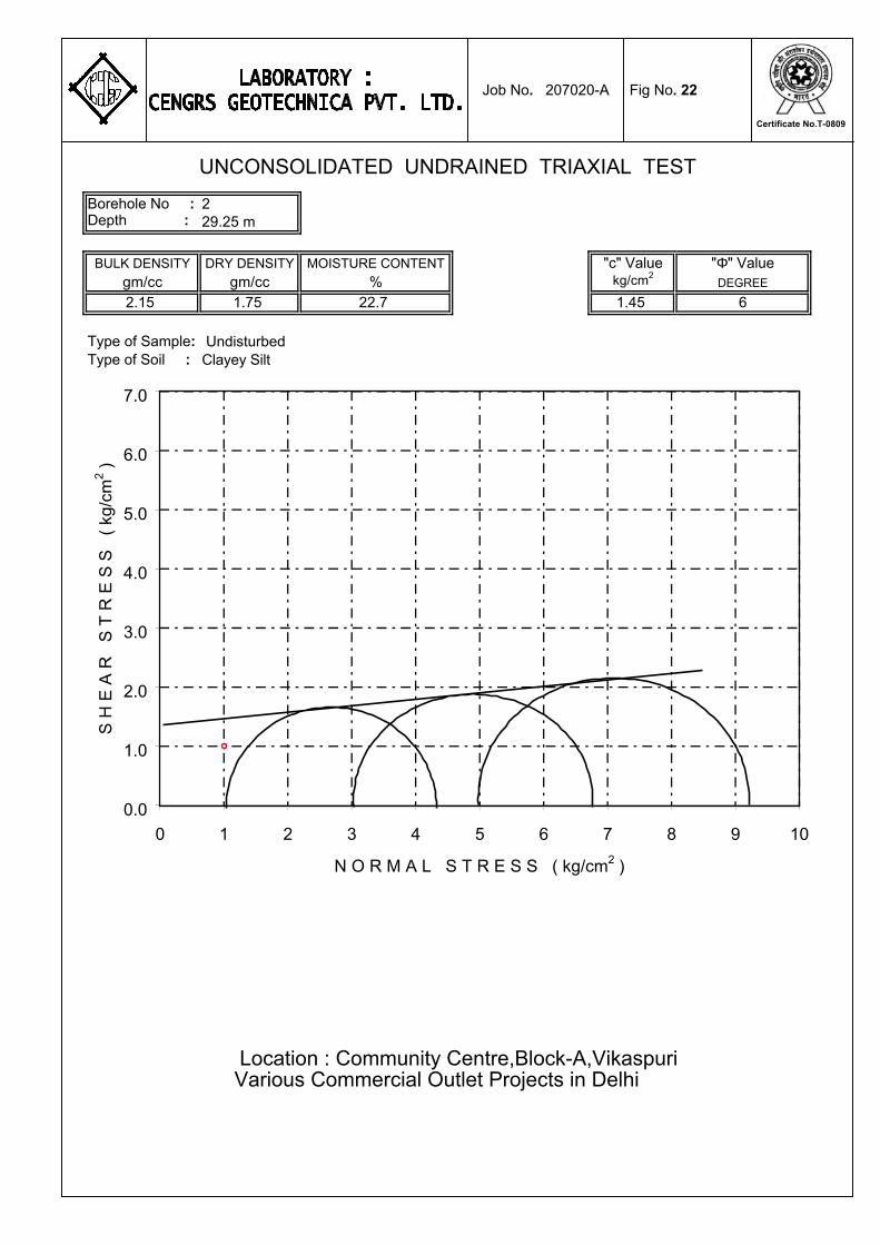
Borehole No : 2Depth : 29.25 m
BULK DENSITY DRY DENSITY MOISTURE CONTENT "c" Value "Φ" Valuegm/cc gm/cc % kg/cm2
DEGREE
2.15 1.75 22.7 1.45 6
Type of Sample: UndisturbedType of Soil : Clayey Silt
Various Commercial Outlet Projects in Delhi
UNCONSOLIDATED UNDRAINED TRIAXIAL TEST
Location : Community Centre,Block-A,Vikaspuri
0.0
1.0
2.0
3.0
4.0
5.0
6.0
7.0
0 1 2 3 4 5 6 7 8 9 10
N O R M A L S T R E S S ( kg/cm2 )
S H
E A
R
S T
R E
S S
(
kg
/cm
2 )
Job No. 207020-A Fig No. 22
Certificate No.T-0809

Borehole No : 3 Dry Density "c" Value "Φ" ValueDepth : 2.25 m gm/cc kg/cm2
DEGREE
1.55 0 32
Type of Test : Saturated Consolidated Drained Type of Soil : Silty Fine Sand
D R A I N E D D I R E C T S H E A R T E S T
Location : Community Centre,Block-A,VikaspuriVarious Commercial Outlet Projects in Delhi
0.0
0.5
1.0
1.5
2.0
2.5
0 0.5 1 1.5 2 2.5 3 3.5
N O R M A L S T R E S S ( kg/cm2 )
S H
E A
R S
T R
E S
S (
kg/c
m2 )
Job No. 207020-A Fig No. 23
Certificate No.T-0809

Borehole No : 3 Dry Density "c" Value "Φ" ValueDepth : 11.25 m gm/cc kg/cm2
DEGREE
1.64 0 36
Type of Test : Saturated Consolidated Drained Type of Soil : Silty Fine Sand
D R A I N E D D I R E C T S H E A R T E S T
Location : Community Centre,Block-A,VikaspuriVarious Commercial Outlet Projects in Delhi
0.0
0.5
1.0
1.5
2.0
2.5
0 0.5 1 1.5 2 2.5 3 3.5
N O R M A L S T R E S S ( kg/cm2 )
S H
E A
R S
T R
E S
S (
kg/c
m2 )
Job No. 207020-A Fig No. 24
Certificate No.T-0809
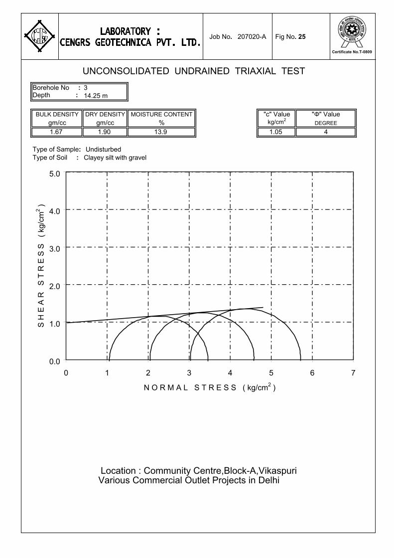
Borehole No : 3Depth : 14.25 m
BULK DENSITY DRY DENSITY MOISTURE CONTENT "c" Value "Φ" Valuegm/cc gm/cc % kg/cm2
DEGREE
1.67 1.90 13.9 1.05 4
Type of Sample: UndisturbedType of Soil : Clayey silt with gravel
Various Commercial Outlet Projects in Delhi
UNCONSOLIDATED UNDRAINED TRIAXIAL TEST
Location : Community Centre,Block-A,Vikaspuri
0.0
1.0
2.0
3.0
4.0
5.0
0 1 2 3 4 5 6 7
N O R M A L S T R E S S ( kg/cm2 )
S H
E A
R
S T
R E
S S
(
kg/c
m2 )
Job No. 207020-A Fig No. 25
Certificate No.T-0809
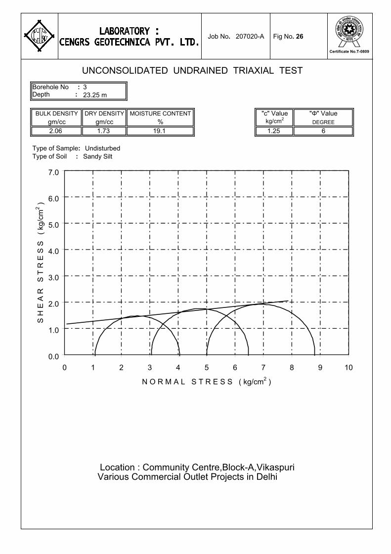
Borehole No : 3Depth : 23.25 m
BULK DENSITY DRY DENSITY MOISTURE CONTENT "c" Value "Φ" Valuegm/cc gm/cc % kg/cm2
DEGREE
2.06 1.73 19.1 1.25 6
Type of Sample: UndisturbedType of Soil : Sandy Silt
Various Commercial Outlet Projects in Delhi
UNCONSOLIDATED UNDRAINED TRIAXIAL TEST
Location : Community Centre,Block-A,Vikaspuri
0.0
1.0
2.0
3.0
4.0
5.0
6.0
7.0
0 1 2 3 4 5 6 7 8 9 10
N O R M A L S T R E S S ( kg/cm2 )
S H
E A
R
S T
R E
S S
(
kg
/cm
2 )
Job No. 207020-A Fig No. 26
Certificate No.T-0809
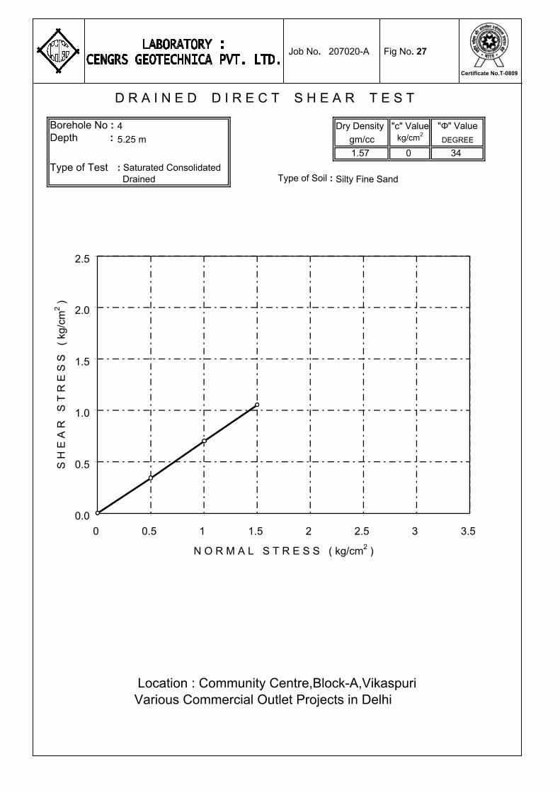
Borehole No : 4 Dry Density "c" Value "Φ" ValueDepth : 5.25 m gm/cc kg/cm2
DEGREE
1.57 0 34
Type of Test : Saturated Consolidated Drained Type of Soil : Silty Fine Sand
D R A I N E D D I R E C T S H E A R T E S T
Location : Community Centre,Block-A,VikaspuriVarious Commercial Outlet Projects in Delhi
0.0
0.5
1.0
1.5
2.0
2.5
0 0.5 1 1.5 2 2.5 3 3.5
N O R M A L S T R E S S ( kg/cm2 )
S H
E A
R S
T R
E S
S (
kg/c
m2 )
Job No. 207020-A Fig No. 27
Certificate No.T-0809
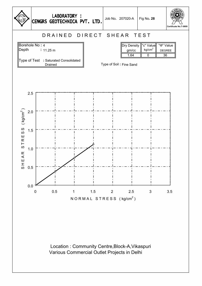
Borehole No : 4 Dry Density "c" Value "Φ" ValueDepth : 11.25 m gm/cc kg/cm2
DEGREE
1.64 0 36
Type of Test : Saturated Consolidated Drained Type of Soil : Fine Sand
D R A I N E D D I R E C T S H E A R T E S T
Location : Community Centre,Block-A,VikaspuriVarious Commercial Outlet Projects in Delhi
0.0
0.5
1.0
1.5
2.0
2.5
0 0.5 1 1.5 2 2.5 3 3.5
N O R M A L S T R E S S ( kg/cm2 )
S H
E A
R S
T R
E S
S (
kg/c
m2 )
Job No. 207020-A Fig No. 28
Certificate No.T-0809

Borehole No : 4 Dry Density "c" Value "Φ" ValueDepth : 23.25 m gm/cc kg/cm2
DEGREE
1.73 0 38
Type of Test : Saturated Consolidated Drained Type of Soil : Silty Fine Sand
D R A I N E D D I R E C T S H E A R T E S T
Location : Community Centre,Block-A,VikaspuriVarious Commercial Outlet Projects in Delhi
0.0
0.5
1.0
1.5
2.0
2.5
0 0.5 1 1.5 2 2.5 3 3.5
N O R M A L S T R E S S ( kg/cm2 )
S H
E A
R S
T R
E S
S (
kg/c
m2 )
Job No. 207020-A Fig No. 29
Certificate No.T-0809
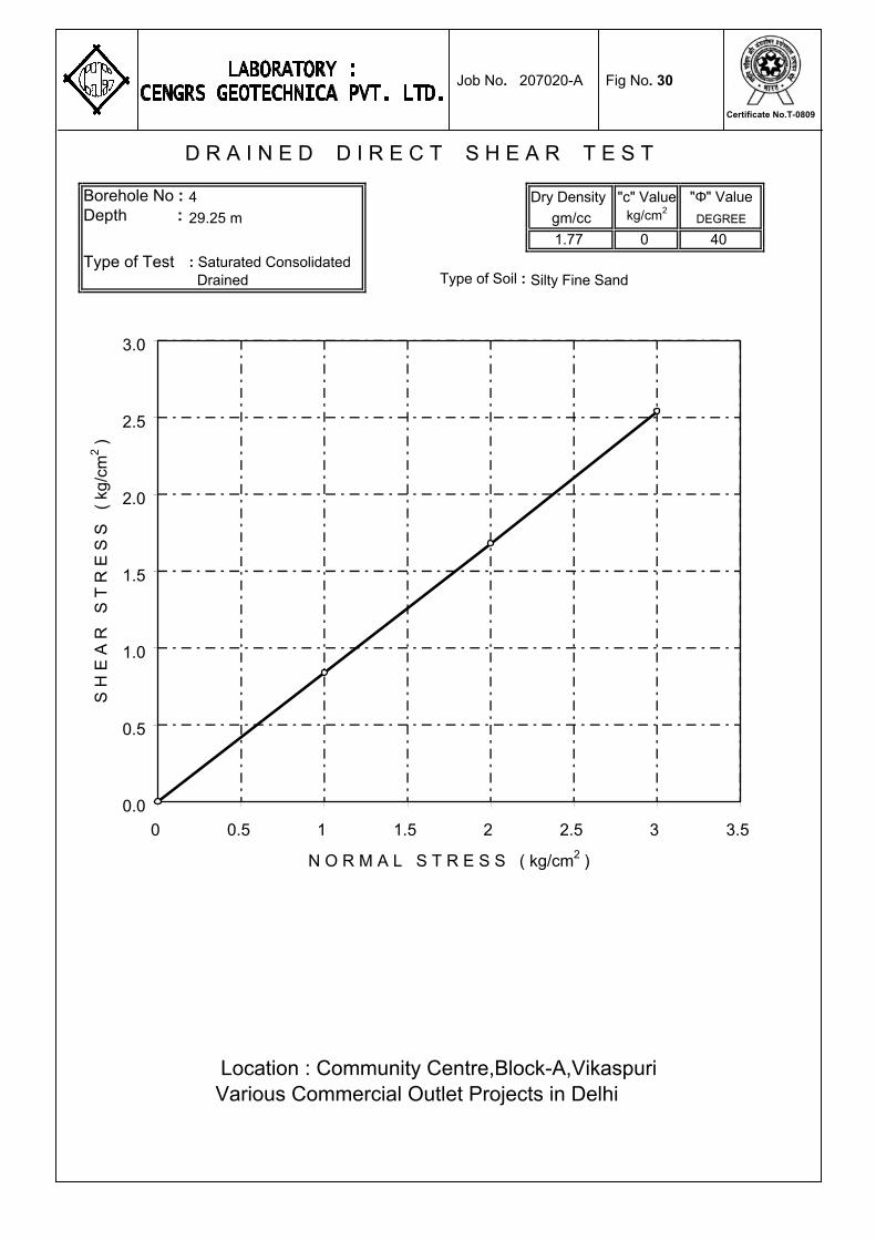
Borehole No : 4 Dry Density "c" Value "Φ" ValueDepth : 29.25 m gm/cc kg/cm2
DEGREE
1.77 0 40
Type of Test : Saturated Consolidated Drained Type of Soil : Silty Fine Sand
D R A I N E D D I R E C T S H E A R T E S T
Location : Community Centre,Block-A,VikaspuriVarious Commercial Outlet Projects in Delhi
0.0
0.5
1.0
1.5
2.0
2.5
3.0
0 0.5 1 1.5 2 2.5 3 3.5
N O R M A L S T R E S S ( kg/cm2 )
S H
E A
R S
T R
E S
S (
kg/c
m2 )
Job No. 207020-A Fig No. 30
Certificate No.T-0809

Borehole No : 5 Dry Density "c" Value "Φ" ValueDepth : 5.25 m gm/cc kg/cm2
DEGREE
1.56 0 33
Type of Test : Saturated Consolidated Drained Type of Soil : Silty Fine Sand
D R A I N E D D I R E C T S H E A R T E S T
Location : Community Centre,Block-A,VikaspuriVarious Commercial Outlet Projects in Delhi
0.0
0.5
1.0
1.5
2.0
2.5
3.0
0 0.5 1 1.5 2 2.5 3 3.5
N O R M A L S T R E S S ( kg/cm2 )
S H
E A
R S
T R
E S
S (
kg/c
m2 )
Job No. 207020-A Fig No. 31
Certificate No.T-0809
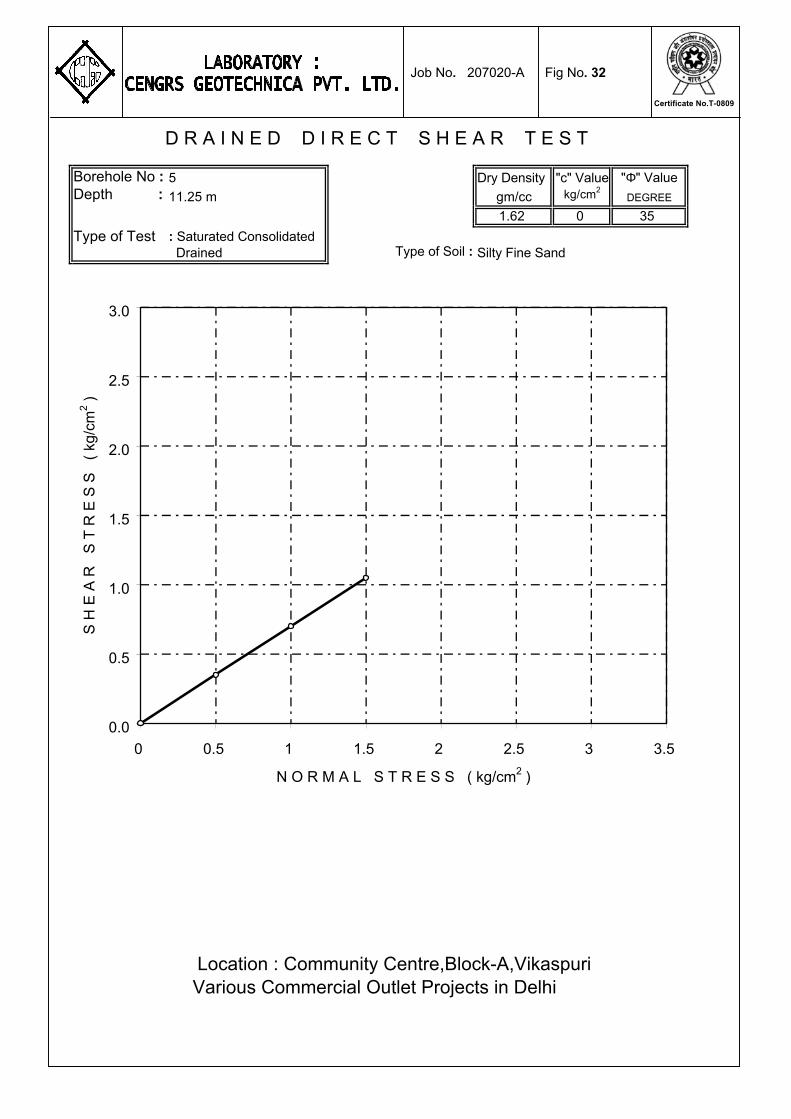
Borehole No : 5 Dry Density "c" Value "Φ" ValueDepth : 11.25 m gm/cc kg/cm2
DEGREE
1.62 0 35
Type of Test : Saturated Consolidated Drained Type of Soil : Silty Fine Sand
D R A I N E D D I R E C T S H E A R T E S T
Location : Community Centre,Block-A,VikaspuriVarious Commercial Outlet Projects in Delhi
0.0
0.5
1.0
1.5
2.0
2.5
3.0
0 0.5 1 1.5 2 2.5 3 3.5
N O R M A L S T R E S S ( kg/cm2 )
S H
E A
R S
T R
E S
S (
kg/c
m2 )
Job No. 207020-A Fig No. 32
Certificate No.T-0809
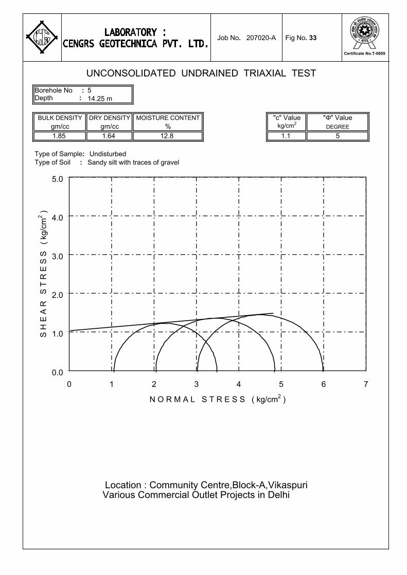
Borehole No : 5Depth : 14.25 m
BULK DENSITY DRY DENSITY MOISTURE CONTENT "c" Value "Φ" Valuegm/cc gm/cc % kg/cm2
DEGREE
1.85 1.64 12.8 1.1 5
Type of Sample: UndisturbedType of Soil : Sandy silt with traces of gravel
Various Commercial Outlet Projects in Delhi
UNCONSOLIDATED UNDRAINED TRIAXIAL TEST
Location : Community Centre,Block-A,Vikaspuri
0.0
1.0
2.0
3.0
4.0
5.0
0 1 2 3 4 5 6 7
N O R M A L S T R E S S ( kg/cm2 )
S H
E A
R
S T
R E
S S
(
kg/c
m2 )
Job No. 207020-A Fig No. 33
Certificate No.T-0809

Borehole No : 5 Dry Density "c" Value "Φ" ValueDepth : 29.25 m gm/cc kg/cm2
DEGREE
1.75 0 39
Type of Test : Saturated Consolidated Drained Type of Soil : Fine Sand
D R A I N E D D I R E C T S H E A R T E S T
Location : Community Centre,Block-A,VikaspuriVarious Commercial Outlet Projects in Delhi
0.0
0.5
1.0
1.5
2.0
2.5
3.0
0 0.5 1 1.5 2 2.5 3 3.5
N O R M A L S T R E S S ( kg/cm2 )
S H
E A
R S
T R
E S
S (
kg/c
m2 )
Job No. 207020-A Fig No. 34
Certificate No.T-0809
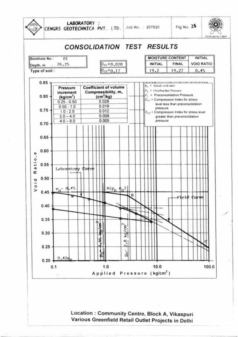
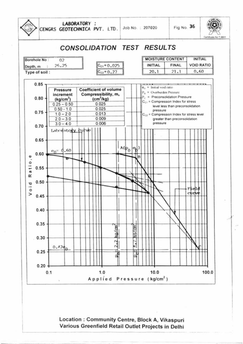
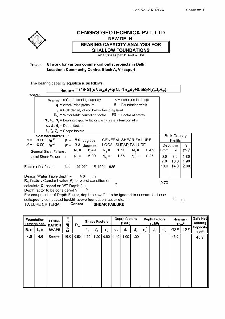
Job No. 207020-A Sheet no.1
c =
B =
FS =
c = 9.00 T/m2 φ = 5.0c' = 6.00 T/m2 φ'= 3.3 γ
Nc = Nq = Nγ = From To T/m3
Nc' = Nq
' = Nγ' = 0.0 7.0 1.80
7.0 10.0 1.902.5 10.0 14.0 2.00
C0.70
Y
1.0
B, m L, m ζc ζq ζγ dc dq dγ dc' dq' dγ
' GSF LSF
4.0 4.0 Square 10.0 0.50 1.30 1.20 0.80 1.49 1.00 1.00 48.9
0.45
0.27
GENERAL SHEAR FAILURELOCAL SHEAR FAILURE
Dep
th,m Depth factors
(GSF)
General
6.49
as per
5.99 1.35
1.57
Local Shear Failure :
GI work for various commercial outlet projects in Delhi
Location : Community Centre, Block A, Vikaspuri
The bearing capacity equation is as follows :
where:
Depth factors (LSF)
Shape Factors
Foundation Dimensions
48.9
Rw
FOUN-DATION SHAPE
Safe Net Bearing Capacity
T/m2
BEARING CAPACITY ANALYSIS FOR SHALLOW FOUNDATIONS
qnet safe = (1/FS){cNcζcdc+q(Nq-1)ζqdq+0.5BγNγζγdγRw}
Depth factor to be considered ?
Depth, m
Factor of safety =
qnet safe ,
T/m2
Rw factor: Constant value(V) for worst condition or
calculate(C) based on WT Depth ? :
Project :
overburden pressure
CENGRS GEOTECHNICA PVT. LTDNEW DELHI
Analysis as per IS 6403-1981
Factor of safety
degrees
degrees
Bulk Density Profile
Soil parameters :
Rw =
dc, dq, dγ =
bearing capacity factors, which are a function of φNc, Nq, Nγ =
Water table correction factor
m SHEAR FAILURE
General Shear Failure :
FAILURE CRITERIA :
For computation of Depth Factor, depth below GL to be ignored to account for loose soils,poorly compacted backfill above foundation, scour etc. =
4.0
IS 1904-1986
Design Water Table depth = m
qnet safe =
Depth factors
Shape factors
q =
γ =
ζc, ζq, ζγ =
cohesion intercept
Foundation width
Bulk density of soil below founding level
safe net bearing capacity
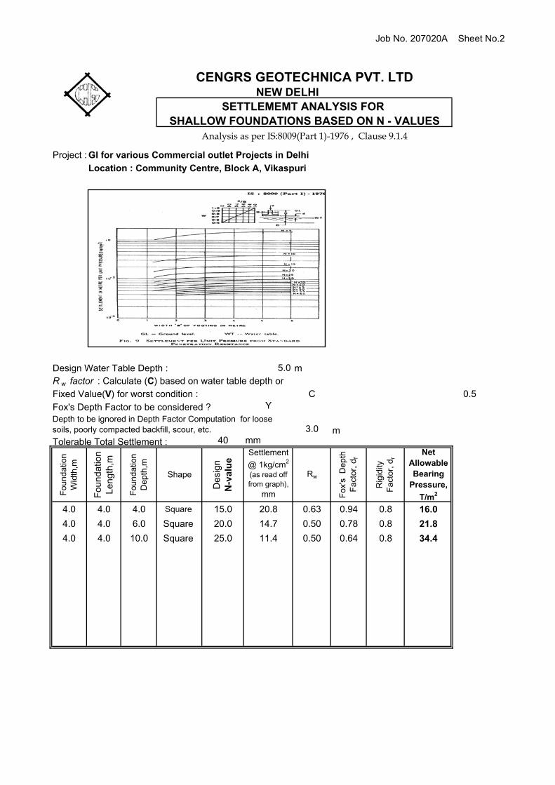
Job No. 207020A Sheet No.2
Project :
C 0.5Y
3.040 mm
Foundatio
n
Wid
th,m
Fo
un
da
tion
L
en
gth
,m
Foundatio
n
Depth
,m
Shape
Desi
gn
N-v
alu
e
Settlement
@ 1kg/cm2
(as read off from graph),
mm
Rw
Fox'
s D
epth
F
act
or,
df
Rig
idity
F
act
or,
dr
Net Allowable Bearing
Pressure,
T/m2
4.0 4.0 4.0 Square 15.0 20.8 0.63 0.94 0.8 16.0
4.0 4.0 6.0 Square 20.0 14.7 0.50 0.78 0.8 21.8
4.0 4.0 10.0 Square 25.0 11.4 0.50 0.64 0.8 34.4
GI for various Commercial outlet Projects in Delhi
Location : Community Centre, Block A, Vikaspuri
Analysis as per IS:8009(Part 1)-1976 , Clause 9.1.4
CENGRS GEOTECHNICA PVT. LTD
SHALLOW FOUNDATIONS BASED ON N - VALUESSETTLEMEMT ANALYSIS FOR
NEW DELHI
Tolerable Total Settlement :
Design Water Table Depth :
Fox's Depth Factor to be considered ?
m
m
Depth to be ignored in Depth Factor Computation for loose soils, poorly compacted backfill, scour, etc.
R w factor : Calculate (C) based on water table depth or
Fixed Value(V) for worst condition :
5.0
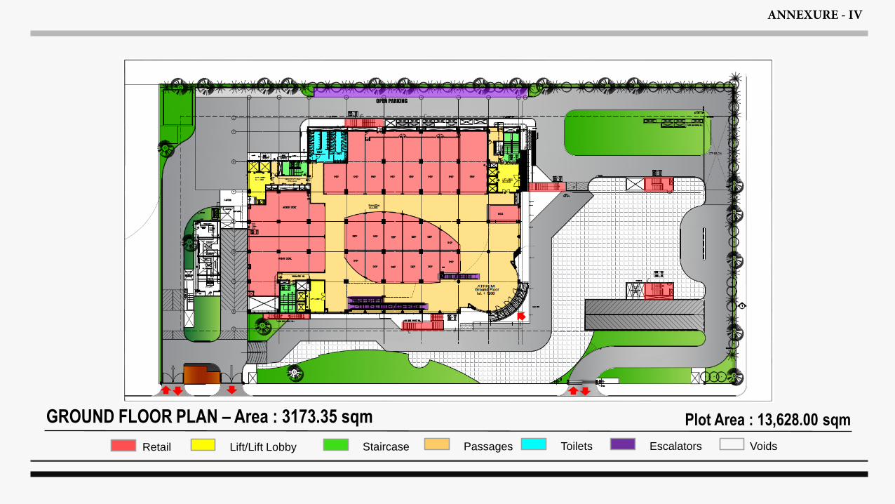
GROUND FLOOR PLAN – Area : 3173.35 sqm
OPEN PARKING
Retail Lift/Lift Lobby Staircase Passages Toilets Escalators Voids
Plot Area : 13,628.00 sqm
ANNEXURE - IV
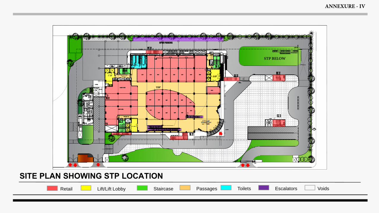
SITE PLAN SHOWING STP LOCATION
OPEN PARKING
Retail Lift/Lift Lobby Staircase Passages Toilets Escalators Voids
ANNEXURE - IV
STP BELOW
saravanan.thamizhave
Rectangle
saravanan.thamizhave
Line
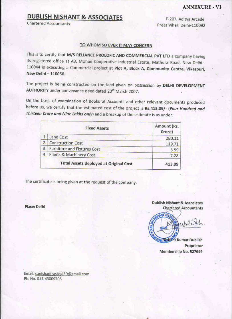
ANNEXURE - VI
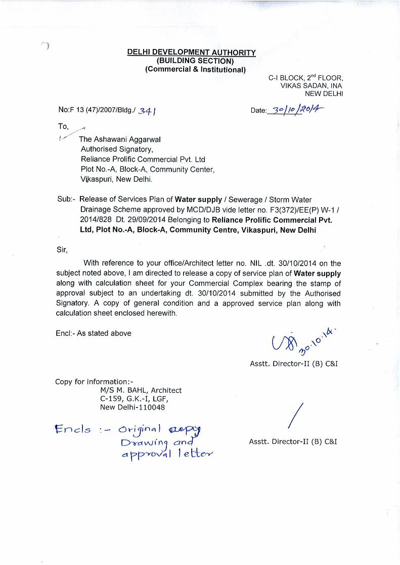
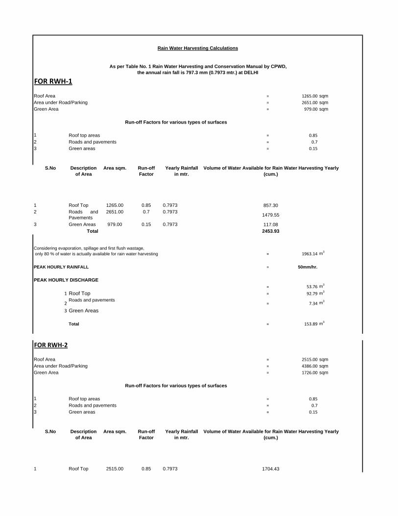
FOR RWH‐1
Roof Area = 1265.00 sqmArea under Road/Parking = 2651.00 sqmGreen Area = 979.00 sqm
1 = 0.852 = 0.73 Green areas = 0.15
S.No Description of Area
Area sqm. Run-off Factor
Yearly Rainfall in mtr.
1 Roof Top 1265.00 0.85 0.79732 Roads and
Pavements 2651.00 0.7 0.7973
3 Green Areas 979.00 0.15 0.7973Total
= 1963.14 m3
PEAK HOURLY RAINFALL = 50mm/hr.
= 53.76 m3
1 Roof Top = 92.79 m3
2Roads and pavements
= 7.34 m3
3 Green Areas
Total = 153.89 m3
FOR RWH‐2
Roof Area = 2515.00 sqmArea under Road/Parking = 4386.00 sqmGreen Area = 1726.00 sqm
1 = 0.852 = 0.73 Green areas = 0.15
S.No Description of Area
Area sqm. Run-off Factor
Yearly Rainfall in mtr.
1 Roof Top 2515.00 0.85 0.7973
Rain Water Harvesting Calculations
Volume of Water Available for Rain Water Harvesting Yearly (cum.)
As per Table No. 1 Rain Water Harvesting and Conservation Manual by CPWD, the annual rain fall is 797.3 mm (0.7973 mtr.) at DELHI
Run-off Factors for various types of surfaces
Roof top areasRoads and pavements
857.30
1479.55
117.082453.93
Volume of Water Available for Rain Water Harvesting Yearly (cum.)
Run-off Factors for various types of surfaces
Roof top areasRoads and pavements
Considering evaporation, spillage and first flush wastage, only 80 % of water is actually available for rain water harvesting
PEAK HOURLY DISCHARGE
1704.43
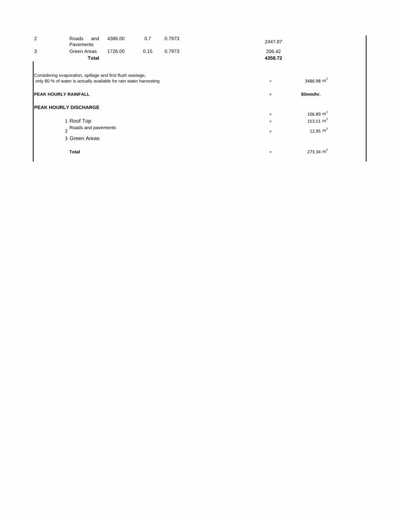
2 Roads andPavements
4386.00 0.7 0.7973
3 Green Areas 1726.00 0.15 0.7973Total
= 3486.98 m3
PEAK HOURLY RAINFALL = 50mm/hr.
= 106.89 m3
1 Roof Top = 153.51 m3
2Roads and pavements
= 12.95 m3
3 Green Areas
Total = 273.34 m3
Considering evaporation, spillage and first flush wastage, only 80 % of water is actually available for rain water harvesting
PEAK HOURLY DISCHARGE
2447.87
206.424358.72