FORM 1 APPLICATION FORM - Welcome to...
79
Form 1 1 FORM 1 APPLICATION FORM I Basic Information Sl. No. Item Details 1. Name of the Project : ACCORD ENERGY CORPORATION INDIA PRIVATE LIMITED Proposed Modification - Coal Based Thermal Power Plant 2. S. No. in the schedule : 1 (d) – Category < 500 MW Coal based Power Plant. 3. Proposed capacity / area/length/ tonnage to be handled /command area/ lease area / number of wells to be drilled : As per Existing Environment Clearance Proposed Change 2 x 150 MW (Yet to Start Construction) 2 x 180 MW 4. New/Expansion/Modernization : 5. Existing Capacity / Area etc. : 160 Acres Existing Environmental Clearance vide letter # J-13012/107/ 2009-IA-II (T) dated 18/05/2011 Copy of Environmental Clearance is enclosed in Annexure I & Minutes of Meeting of the 34th meeting of re-constituted Expert Appraisal Committee (Thermal) held on 10th & 11th October, 2011 Copy of which is enclosed in Annexure II. Issue of Consent to Establish by TNPCB is in final stages. Construction will commence after obtaining Consent to Establish from TNPCB. 6. Category of Project ie. “A” or “B” : Category “A” 7. Does it attract the general condition? If yes, please specify. : Yes. ( The plant site lies within 10 km of the Interstate boundary- Tamil Nadu and Andhra Pradesh) 8. Does it attract the specific condition? If yes, please specify. : No
Transcript of FORM 1 APPLICATION FORM - Welcome to...
Form 1
1
FORM 1
APPLICATION FORM
I Basic Information
Sl. No. Item Details
1. Name of the Project : ACCORD ENERGY CORP ORATION
INDIA P RIVATE LIMITED
Proposed Modification - Coal Based Thermal
Power Plant
2. S. No. in the schedule : 1 (d) – Category < 500 MW Coal based Power
Plant.
3. Proposed capacity / area/length/ tonnage
to be handled /command area/ lease area
/ number of wells to be drilled
: As per Existing
Environment
Clearance
Proposed Change
2 x 150 MW
(Yet to Start
Construction)
2 x 180 MW
4. New/Expansion/Modernization :
5. Existing Capacity / Area etc. : 160 Acres
Existing Environmental Clearance vide letter
# J-13012/107/ 2009-IA-II (T) dated 18/05/2011
Copy of Environmental Clearance is enclosed in
Annexure I & Minutes of Meeting of the 34th
meeting of re-constituted Expert Appraisal
Committee (Thermal) held on 10th & 11th
October, 2011 Copy of which is enclosed in
Annexure II.
Issue of Consent to Establish by TNPCB is in final
stages.
Construction will commence after obtaining
Consent to Establish from TNPCB.
6. Category of Project ie. “A” or “B” : Category “A”
7. Does it attract the general condition? If
yes, please specify.
: Yes. ( The plant site lies within 10 km of the
Interstate boundary- Tamil Nadu and Andhra
Pradesh)
8. Does it attract the specific condition? If
yes, please specify.
: No

Form 1
2
9. Location
Plot/Survey/Khasra No. : Please refer Anneuxre III
Village : Sirupuzhalpettai
Tehsil : Gummidipoondi
District : Thiruvallur
State : Tamil Nadu
10 Nearest railway station/airport alongwith
distance in kms.
: Railway Station - Gummidipoondi – 5km
Airport - Chennai – 50 km
11 Nearest Town, City, District
Headquarters alongwith distance in kms
: Town - Gummidipoondi – 5km
District Headquarters – Thiruvallur – 39 km
12 Village Panchayats, Zilla Parishad,
Municipal Corporation, Local Body
(complete postal addresses with
telephone nos. to be given).
: Gummidipoondi
13. Name of the applicant : ACCORD ENERGY CORPORATION
INDIA PRIVATE LIMITED
14. Registered Address : #29, Thilak Street, T Nagar,
Chennai - 600017
15. Address for correspondence : ACCORD ENERGY CORPORATION
INDIA PRIVATE LIMITED
#29, Thilak Street, T Nagar,
Chennai - 600017
Name : M. Viswanathan
Designation (Owner/Partner/CEO) : Senior Project Manager
Address #29, Thilak Street, T Nagar,
Chennai - 600017
Pin Code 600 017
E-mail [email protected]
Telephone No. 044- 28346505
Fax No. 044 - 28341447

Form 1
3
16. Details of Alternative Sites examined, if
any.
Location of these sites should be shown
on a topo sheet.
: Not Applicable.
The present application is for augmentation of
capacity from 2 x 150 MW to 2 x 180 MW, the
Environmental Clearance for 2 x 150 MW has
already been obtained. Issue of Consent to
Establish by TNPCB is in final stages.
Construction will commence after obtaining
Consent to Establish from TNPCB.
17. Interlined Projects : None
18. Whether separate application of
interlined project has been submitted
: -
19. If yes, date of submission : -
20. If no, reason : -
21. Whether the proposal involves
approval/clearance under:
(a) The Forest (Conservation) Act, 1980
(b) The Wildlife (Protection) Act, 1972
(c) The C.R.Z Notification, 1991
: No
22. Whether there is any Government Order
/ Policy relevant / relating to the site?
: No
23. Forest land involved (hectares) : No
24. Whether there is any litigation pending
against the project and / or land in
which the project is proposed to be set
up
(a) Name of the Court
(b) Case No.
(c) Orders/directions of the Court, if any
and its relevance with the proposed
project.
: No

Form 1
4
II Activity
1. Construction, operation or decommissioning of the Project involving actions,
which will cause physical changes in the locality (topography, land use,
changes in water bodies, etc.)
S.No. Information/Checklist
confirmation
Yes/No Details thereof (with approximate
quantities /rates, wherever possible) with
source of information data
1.1 Permanent or temporary change in
land use, land cover or topography
including increase in intensity of
land use (with respect to
local land use plan)
No Proposed augmentation of capacity from 2
x 150 MW to 2 x180 MW within the existing
premises, for which, Environmental
Clearance was issued vide letter # J-
13012/107/ 2009-IA-II(T) dated
18/05/2011. Copy of Environmental
Clearance is enclosed in Annexure I.
Issue of Consent to Establish by TNPCB is
in final stages.
Hence, No Change in Land Use, Land
Cover or Topography.
1.2 Clearance of existing land,
vegetation and buildings?
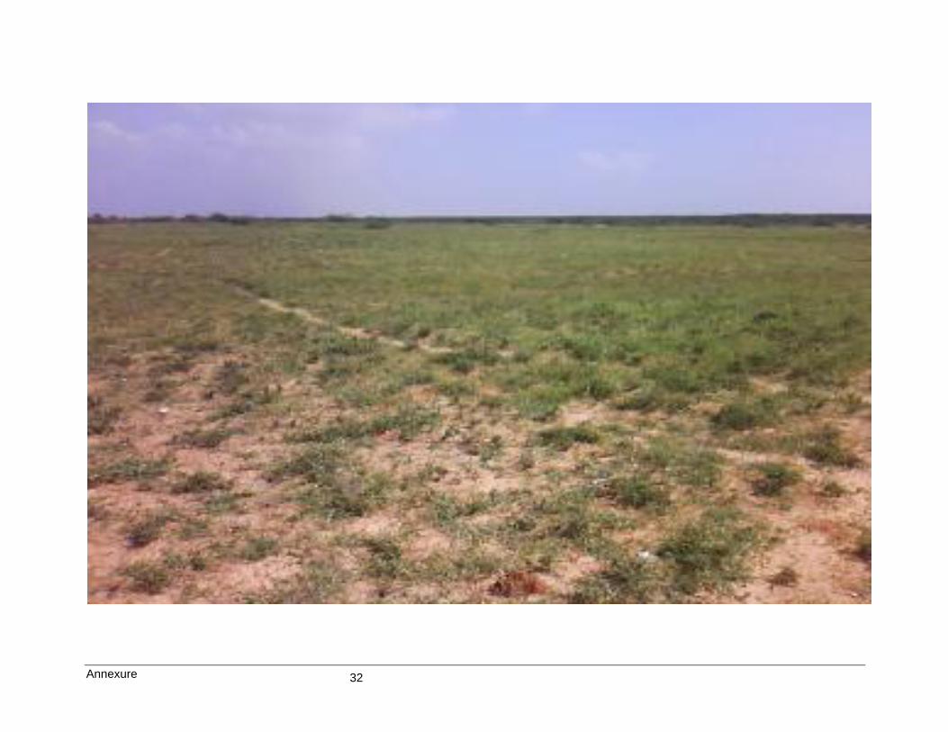
No Photograph enclosed in Annexure IV.
1.3 Creation of new land uses? No -
1.4 Pre-construction investigations e.g.
bore houses, soil testing?
Yes Soil Investigation Work has already been
completed.
1.5 Construction works? Yes Construction is yet to commence.
Environmental Clearance was issued by
MoEF vide letter # J-13012/107/ 2009-IA-
II(T) dated 18/05/2011.
Issue of Consent to Establish by TNPCB is
in final stages.
Construction will commence after obtaining
Consent to Establish from TNPCB.
However, the proposed power plant will
have boiler house, turbine hall, ACC,
Switch Yard etc.
1.6 Demolition works? No -
1.7 Temporary sites used for
construction works or housing of
construction workers?
Yes There will be total of 600 construction
workers including Fabricators, Erecters
etc. accommodated in 100 rooms with
facility for bathing, sanitation etc., at the
time of construction.

Form 1
5
1.8 Above ground buildings, structures
or earthworks including linear
structures, cut and fill or
excavations.
Yes Plant Layout enclosed.
Please refer Annexure-V
1.9 Underground works including
mining or tunneling?
No -
1.10 Reclamation works? No -
1.11 Dredging? No -
1.12 Offshore structures? No -
1.13 Production and manufacturing
processes?
Yes Please refer Annexure VI
1.14 Facilities for storage of goods or
materials?
Yes Please refer Annexure V
1.15 Facilities for treatment or disposal
of solid waste or liquid effluents?
Yes Please refer Annexure VII
1.16 Facilities for long term housing of
operational workers?
No There are no facilities proposed within
plant site or outside.
1.17 New road, rail or sea traffic during
construction or operation?
Yes The present application is for augmentation
of capacity from 2 x 150 MW to 2x180MW.
2 x 150 MW that had already been cleared
by MoEF, New Delhi.
Coal will be transported from Ennore Port
to site by Road for the first 4 years from the
commencement of power plant.
From 5th year onward, the coal will be
transported from port to site by rail.
The Increase in traffic due to this present
augmentation will also be very marginal in
comparison to the original proposed with
respect to 2 x 150MW.
1.18 New road, rail, air waterborne or
other transport infrastructure
including new or altered routes and
stations, ports, airports etc?
No
1.19 Closure or diversion of existing
transport routes or infrastructure
leading to changes in traffic
movements?
No
1.20 New or diverted transmission lines
or pipelines?
Yes A 230/400 KV Transmission line connecting
to Thervoikandigai substation at 6.5 km
from site.
1.21 Impoundment, damming,
culverting, realignment or other
changes to the hydrology of
watercourses or aquifers?
No -
1.22 Stream crossings? Yes Araniyar River, which is 7.5 km in SSE from
the Plant Site.

Form 1
6
1.23 Abstraction or transfers of water
from ground or surface waters?
* Reduction in Water Consumption
due to
- use of Fin Fan Coolers for
Turbine Generator.
Yes Ground Water/ Rainwater Harvesting
Clearance from Central Ground Water
Authority has already been obtained for
drawl of 1300 KLD of Ground Water. Copy
of which is enclosed in Annexure VIII.
Water Consumption
for 2x150 MW
(As per Environmental
Clearance)
Water Consumption
for 2x180 MW
(Daily Make-up)
802 KLD 150 KLD*
150 KLD is the daily make-up after recycling
192 KLD of treated waste water.
Water Balance Diagram is enclosed in
Annexure IX.
1.24 Changes in water bodies or the
land surface affecting drainage or
run-off?
No The present application is for augmentation
of plant capacity from 2 x 150 MW to
2 x 180 MW within the project site for which
environmental clearance has been obtained.
However, Waterbodies & Drainage Map is
enclosed in Annexure X.
1.25 Transport of personnel or materials
for construction, operation or
decommissioning?
Yes The existing transport facilities will be made
use of, to commute employees / workers.
Transportation of coal by road upto 4 years
of commissioning of plant and thereafter by
rail.
1.26 Long-term dismantling or
decommissioning or restoration
works?
No -
1.27 Ongoing activity during
decommissioning which could
have an impact on the
environment?
No -
1.28 Influx of people to an area in either
temporarily or permanently?
Yes About 600 workers during construction and
about 50 direct & 25 indirect during
operation.
1.29 Introduction of alien species? No -
1.30 Loss of native species or genetic
diversity?
No -
1.31 Any other actions? - -

Form 1
7
2. Use of Natural resources for construction or operation of the Project (such as land, water,
materials or energy, especially any resources which are non-renewable or in short supply):
S.No. Information/Checklist confirmation Yes/No Details thereof (with approximate
quantities /rates, wherever possible) with
source of information data
2.1 Land especially undeveloped or
agricultural land (ha)
No The present application is for augmentation of Capacity from 2 x 150 MW to 2 x 180 MW within the existing plant site for which Environmental Clearance has already been obtained and construction is yet to start.
2.2 Water (expected source & competing
users) unit: KLD
* Reduction in Water consumption due
to
- use of Fin Fan Coolers for
Turbine Generator.
Yes Source of water will be Harvested Rain Water
/ Ground Water. Sufficient draft is available
the total water requirement for 2 x 180 MW
on daily make-up will be 150 KLD.
Clearance from Central Ground Water Authority has already been obtained for drawl of 1300 KLD of Ground Water. Copy of which is enclosed in Annexure VIII.
Water Consumption
Water Consumption
for 2x150 MW (As
per Environmental
Clearance)
Water Consumption
for 2x180 MW (Daily
Make-up)
802 KLD 150 KLD
150 KLD is the daily make-up after recycling
192 KLD of treated waste water.
Water Balance Diagram is enclosed in
Annexure IX.
2.3 Minerals (MT)
* At heat rate of 2341 kcal/kwh
Yes Coal Consumption
for 2x150 MW for 2x180MW Additional
Coal
requirement
(ie from 300
MW to 360
MW)
3600 TPD 3815 TPD* 215 TPD
2.4 Construction material - stone, aggregates,
sand / soil (expected source – MT)
Yes Predominantly Steel Structures
2.5 Forests and timber (source – MT) No -
2.6 Energy including electricity and fuels
(source, competing users) Unit: fuel
(MT), energy (MW)
Yes Auxiliary Power Requirement of the Plant
will be met from its own generation
2.7 Any other natural resources (use
appropriate standard units)
No -

Form 1
8
3. Use, storage, transport, handling or production of substances or materials, which could be
harmful to human health or the environment or raise concerns about actual or perceived
risks to human health.
S.No. Information/Checklist confirmation Yes/No Details thereof (with approximate
quantities /rates, wherever possible)
with source of information data
3.1 Use of substances or materials, which are
hazardous (as per MSIHC rules) to human
health or the environment (flora, fauna, and
water supplies)
None This is a coal based power plant and
hence does not include any chemicals
listed in MSIHC rules.
3.2 Changes in occurrence of disease or affect
disease vectors (e.g. insect or water borne
diseases)
None -
3.3 Affect the welfare of people e.g. by changing
living conditions?
Yes Betterment in the socio – economic
conditions of the areas surrounding the
plant site and improve availability of
power. General improvement in
standard of living.
3.4 Vulnerable groups of people who could be
affected by the project e.g. hospital patients,
children, the elderly etc.,
None -
3.5 Any other causes No -
4. Production of solid wastes during construction or operation or decommissioning
(MT/month)
S.No. Information/Checklist confirmation Yes/No Details thereof (with approximate
quantities /rates, wherever possible)
with source of information data
4.1 Spoil, overburden or mine wastes No -
4.2 Municipal waste (domestic and or
commercial wastes)
No -
4.3 Hazardous wastes (as per Hazardous
Waste Management Rules
No -
4.4 Other industrial process wastes Yes The solid waste will be in the form of
Fly ash & Bottom Ash Solid
Waste
For 2 x
150 MW
(TPD)
Form 2
x 180
MW
(TPD)
Additional
Quantity of
Solid
Waste
Generation
(TPD)
Fly Ash 259.20 274.68 15.48
Bottom
Ash
64.80 68.67 3.87
Total 324.00 343.35 19.35
4.5 Surplus product No -
4.6 Sewage sludge or other sludge from
effluent treatment
Yes Dried Sewage Sludge from Filter Press
of STP – 0.2 T/M.

Form 1
9
4.7 Construction or demolition wastes No -
4.8 Redundant machinery or equipment No -
4.9 Contaminated soils or other materials No -
4.10 Agricultural wastes No -
4.11 Other solid wastes - -
5. Release of pollutants or any hazardous, toxic or noxious substances to air (Kg/hr)
S.No. Information/Checklist confirmation Yes/No Details thereof (with approximate
quantities /rates, wherever possible)
with source of information data
5.1 Emissions from combustion of fossil
fuels from stationary or mobile
sources
Yes There will be twin flue single chimney,
the characteristics of which is given in
Annexure – XI
5.2 Emissions from production processes Yes
5.3 Emissions from materials handling
including storage or transport
Yes Fugitive emissions due to transport of
coal and ash handling. The coal will be
transported in covered trucks and
stored in closed shed. Coal will be
conveyed from storage area through
closed conveyor.
Ash will be brought directly to silo in
dry form and then disposed to cement
plants.
Please refer Annexure XII
5.4 Emissions from construction activities
including plant and equipment
Yes Emission from diesel operated pumps,
concrete mixers, vibrators and
excavators. However these equipments
will be maintained properly to ensure
minimum emissions, more-over
construction activity will be for a short
duration of period.
5.5 Dust or odours from handling of
materials including construction
materials, sewage and waste
Yes This is a coal based power plant and
hence will not have any odour nuisance,
however dust suppression by way of
sprinklers etc., is proposed as in
Annexure XII
5.6 Emissions from incineration of waste No -
5.7 Emissions from burning of waste in
open air (e.g. slash materials,
construction debris)
No -
5.8 Emissions from any other sources - -

Form 1
10
6. Generation of Noise and Vibration, and Emissions of Light and Heat
S.No. Information/Checklist confirmation Yes/No Details thereof (with approximate
quantities /rates, wherever possible)
with source of information data
6.1 From operation of equipment e.g. engines,
ventilation plant, crushers
Yes The main sources of noise in the
proposed Thermal Power Plant are
noise generated by the turbine, blowers,
air cooled condenser, pumps and
loading/ unloading activities of different
power plant processes for producing
power and all the noise generated will
be within the stipulations of the OSHA
standards.
6.2 From industrial or similar processes Yes Same as above.
6.3 From construction or demolition Yes During construction, operation of
construction equipments will result in
intermittent noise.
6.4 From blasting or piling No -
6.5 From construction or operational traffic Yes Noise due to movement of trucks
carrying raw materials/products.
6.6 From lighting or cooling systems Yes Cooling tower fans-90dB(A)
6.7 From any other sources - -
7. Risks of contamination of land or water from releases of pollutants into the ground or into
sewers, surface waters, groundwater, coastal waters or the sea
S.No. Information/Checklist
confirmation
Yes/No Details thereof (with approximate quantities
/rates, wherever possible) with source of
information data
7.1 From handling, storage, use or
spillage of hazardous materials
No There are no hazardous materials used or
generated.

Form 1
11
7.2 From discharge of sewage or other effluents to water or the land (expected mode and place of discharge) * Reduction in blowdown due to
- reduced water consumption due to use of Fin Fan Coolers for Turbine Generator.
No Waste water generated are Boiler Blowdown, & D.M. Plant regeneration waste other than Domestic Sewage.
Parameters Boiler Blow Down
D.M. Plant Regenerant
Waste
Permissible limits for
discharge on land for
irrigation
PH 10.0 – 10.5 5.0 – 9.0 5.5 – 9.0
TDS (mg/l) 200 5000 2100
Temperature, ºC 85 Ambient -
Free Available Chlorine (mg/l) - 0.1 0.5
Suspended solid (mg/l) 50 50 100
Oil & Grease (mg/l) - - 20
Copper (total) (mg/l) - - 1
Iron (total) (mg/l) - - 1
Zinc (mg/l) - - 1
Chromium (total) (mg/l) Nil Nil 0.2
Phosphate (mg/l) 0.1 - 5.0
Waste Water Generation in KLD
For 2 x 150 MW For 2 x 180 MW
Boiler Blow Down 675 285*
D.M. Plant Regeneration Waste
50 55
Domestic Sewage 1.6 1.6
7.3 By deposition of pollutants
emitted to air into the land or
into water
Yes The sources of emission are process
operations. These operations are provided
with adequate measures to have least impact
on the ambient environment, the details of
various air pollution control equipments are
given in Annexure XIII.
7.4 From any other sources No -
7.5 Is there a risk of long term
build up of pollutants in the
environment from these
sources?
No -
8. Risk of accidents during construction or operation of the Project, which could affect human
health or the environment
S.No. Information/Checklist confirmation Yes/No
Details thereof (with approximate
quantities /rates, wherever
possible) with source of
information data
8.1 From explosions, spillages, fires etc
from storage, handling, use or
production of hazardous substances
No -
8.2 From any other causes Yes Details Enclosed in Annexure XIV
8.3 Could the project be affected by natural
disasters causing environmental damage
(e.g. floods, earthquakes, landslides,
cloudburst etc)?
Yes -

Form 1
12
9. Factors which should be considered (such as consequential development) which could lead to
environmental effects or the potential for cumulative impacts with other existing or planned
activities in the locality
S.No. Information/Checklist
confirmation
Yes/No Details thereof (with approximate
quantities / rates, wherever
possible) with source of
information data
9.1 Lead to development of supporting
utilities, ancillary development or
development stimulated by the
project which could have impact on
the environment e.g.:
• Supporting infrastructure (roads,
power supply, waste or waste water
treatment, etc.)
• housing development
• extractive industries
• supply industries
• other
Yes Increased power supply to
state grid
Increased commerce and
related infrastructures
Development of New
Ancillary Industries.
9.2 Lead to after-use of the site, which
could have an impact on the
environment
No -
9.3 Set a precedent for later
developments
Yes Station Heat Rate has been
optimized from 2650 to 2341.
Use of air cooled condenser for
water conservation.
Use of finfan coolers for Auxiliary
Cooling System.
Use of low ash and low sulphur
content coal
Use of entire ash for cement plant.
Proposed to develop 33% of land
with greenbelt
9.4 Have cumulative effects due to
proximity to other existing or
planned projects with similar effects
Yes The baseline status does indicate the
ambient levels of various
environmental attributes are far
within permissible norms.

Form 1
13
III Environmental Sensitivity
S.No. Areas Name/
Identity
Aerial distance (within 15
Km.) Proposed project location
boundary
1. Areas protected under international
conventions, national or local legislation for
their ecological, landscape, cultural or other
related value
No -
2. Areas which are important or sensitive for
ecological reasons - Wetlands, watercourses or
other water bodies, coastal zone, biospheres,
mountains, forests
No -
3. Areas used by protected, important or sensitive
species of flora or fauna for breeding, nesting,
foraging, resting, over wintering, migration
No -
4. Inland, coastal, marine or underground waters Yes Araniyar River – 7.5kms in SSE
5. State, National boundaries Yes Tamil Nadu-Andhra Pradesh border,
which is 7.5 kms away in North..
6. Routes or facilities used by the public for
access to recreation or other tourist, pilgrim
areas
Yes NH – 5 -4.5 km in East
SH-52 – 3.5 km in SW
Southern Railway – 4.752 kms in East
7. Defense installations None -
8. Densely populated or built-up area None -
9. Areas occupied by sensitive man-made land
uses (hospitals, schools, places of worship,
community facilities)
Yes Please refer Annexure XV
10. Areas containing important, high quality or
scarce resources (ground water resources,
surface resources,
forestry, agriculture, fisheries, tourism,
minerals)
None -
11. Areas already subjected to pollution or
environmental damage. (those where existing
legal environmental standards are exceeded)
None -
12. Areas susceptible to natural hazard which could
cause the project to present environmental
problems
(earthquakes, subsidence, landslides, erosion,
flooding or extreme or adverse climatic
conditions)
Yes The area falls under Seismic Zone – III
IV Proposed Terms of Reference
for EIA studies
This application is requesting for
Amendment

Form 1
14
“I hereby given undertaking that the data and information given in the application and
enclosures are true to the best of my knowledge and belief and I am aware that if any part of
the data and information submitted is found to be false or misleading at any stage, the project
will be rejected and clearance give, if any to the project will be revoked at our risk and cost”.
For ACCORD ENERGY CORP ORATION INDIA P RIVATE LTD ,
Date : 17/10/2014
Place : Chennai
Senior Project Manager. ACCORD ENERGY CORP ORATION INDIA P RIVATE LTD
#29, Thilak Street, T Nagar,
Chennai – 600017.
Signature of the applicant
With Name and Full Address
(Project Proponent / Authorized Signatory

Annexure
15
List of Annexures Annexure I Copy of Environmental Clearance Annexure II Minutes of Meeting for Amendment in EC Annexure III Location Map (TOPO MAP) Annexure IV Site Photographs Annexure V Plant Layout Annexure VI Process Description Annexure VII Method of Disposal for Solid and Liquid Waste Annexure VIII Copy of CGWA Clearance Annexure IX Water Balance Diagram Annexure X Drainage & Water Bodies Map Annexure XI Stack Emission Characteristics Annexure XII Fugitive Emission Control Annexure XIII Air Pollution Control Annexure XIV On-site & Off-site Emergency Plan Annexure XV Administrative Set-up Map

Annexure
16
Annexure – I
COPY OF ENVIRONMENTAL CLEARANCE

Annexure
17

Annexure
18

Annexure
19

Annexure
20

Annexure
21
Annexure
22

Annexure
23

Annexure
24

Annexure
25
Annexure – II
MINUTES OF MEETING FOR AMENDMENT IN EC

Annexure
26
Annexure
27

Annexure
28

Annexure
29
Annexure – III
LOCATION MAP (TOPO MAP)

Annexure 30
TOPO MAP

Annexure
31
Annexure – IV
SITE PHOTOGRAPHS
Annexure 32

Annexure
33
Annexure – V
PLANT LAYOUT

Annexure 34
Plant Layout

Annexure
35
Annexure – VI
PROCESS DESCRIPTION

Annexure
36
Process Description
Upgradation of capacity of the power plant from 2 X 150MW (MCR) to 2 X 180MW (MCR) Accord Energy Corporation India Pvt. Ltd at Sirupulalpettai Village, Gummidipoondi Taluk, Thiruvallur District, Tamil Nadu was originally finalised as 2 x 150MW – Maximum Continuous Rating (MCR) with a capacity to produce 2 x 180MW at Valve Wide Open condition (VWO). The power generation at VWO can be achieved only for a few hours in a year, as per manufacturer’s prescription. Accordingly the equipments were sized as given below:
Sl.No. Description Parameters
1 Boiler and its auxiliaries 535tph with a reheater capacity of 477.4tph.
2 Steam turbine generator 150MW (MCR);180MW (VWO) Heat rate: 2125 Kcal/kWh (MCR) 2135 Kcal/kWh (VWO) Generator sized for 150MW.
3 Air cooled condenser 370tph of steam flow
4 Generator transformer 176MVA
5 MS, CRH and HRH piping Designed to carry steam equivalent to 150MW
6 Boiler feed pumps Sized for a steam generation of 580tph.
During the technical meetings with the turbine suppliers,BHEL/Skoda/Siemens, it was understood that the turbine could be modified to generate 2 x 180MW on a continuous basis with a heat rate of 2015Kcal/kwh, by redesigning the turbine and upgrading the generator equivalent to 180MW. This has the following advantages:
a. Keeping the majority of the systems same, there is a possibility of generating 30MW more in each.
b. Much lower heat rate to generate higher capacity with less coal consumption c. Time required is the same d. Better utilisation of the investment made on the transmission line e. The clearances already obtained, will remain the same except an amendment for augmentation
capacity at 2 x 180 MW
Hence, it was decided to go ahead with this proposal. The increase in capacity necessitated the following changes: Sl.No. Description Parameters for 2 x 150MW MCR Revised parameters for
2 x 180MW MCR
1 Boiler and its auxiliaries 535tph with a reheater capacity of 477.4tph each
580 tph with a reheater capacity of 510tph each
2 Steam turbine generator 2 x 150MW (MCR);180MW (VWO) Heat rate: 2125 Kcal/kWh (MCR) 2135Kcal/kWh (VWO) Generator sized for 2 x 150MW.
2 x 180MW (MCR): Heat rate: 2015Kcal/kwh Generator sized for 2 x180MW
3 Air cooled condenser 370tph of steam flow each 400 tph of steam flow each
4 Generator transformer 176MVA each 220MVA each
5 MS, CRH and HRH piping Designed to carry steam equivalent to 2 x 150MW
Designed to carry steam equivalent to 2 x 180MW
6 Boiler feed pumps Sized for a steam generation of 535 tph each
Sized for a steam generation of 580 tph each

Annexure
37
Annexure – VII
METHOD OF DISPOSAL FOR SOLID AND LIQUID WASTE

Annexure
38
Waste Water Treatment Process
The wastewater will be originating from Boiler Blow Down, D.M. Plant regeneration, and
sanitary effluents from plant. All these wastes except sewage will be treated in ETP/RO and
recycled, and the treatment system will consist of
1. Neutralization pit for pH adjustment of the DM Plant regeneration waste.
2. ETP/RO Management System to enable achieve the specified standards for reuse.
3. Minimize waste water generation to as much as possible, and ensure maximum
reuse.
Neutralization of D.M. Plant Regeneration Waste
The pre-treated water, after filtration would be demineralised using ion exchange resins.
These resins are regenerated periodically. This would produce regeneration wastes,
expected to be around 55 cu.m/day. The concentration of total dissolved solids in the
regeneration waste would be about 5,000 mg/l. Moreover, a wide variation of pH is
expected in this water. The pH of the water would be adjusted in a neutralization pit using
suitable acid or alkali & further treated in RO plant to make it suitable for reuse.
Domestic Sewage
Domestic Sewage will be treated in Septic Tank and then dispersed through dispersion
trench within the plant site.

Annexure
39
Solid Waste Management
Among the solid waste likely to be generated from the proposed Thermal power plant, ash
will be most important. The total ash generated will be 343.35 TPD and out of this 20 % is
bed ash and remaining will be fly ash, i.e.274.68 TPD of fly ash, and 68.67 TPD of bed ash.
Fly ash collected in dry form from the ESP hoppers will be stored in ash silo, unloaded in
trucks and same will be sold to potential entrepreneurs mainly manufacturers of brick,
cement and Asbestos cement sheets. The thrust will be given to ash utilization to negate the
disposal problem.
The proposed Unit shall employ dry bed ash handling system wherein the bed ash is
collected dry from the Boiler bottom using conveyors of stainless steel material & stored in
silo. This ash can be sold to cement manufacturers since the unburned carbon content is
within limit and it is collected dry.

Annexure
40
Annexure – VIII
COPY OF GROUND WATER CLEARANCE FROM CGWA

Annexure
41

Annexure
42

Annexure
43
Annexure IX
WATER BALANCE DIAGRAM

Annexure 44
Water Balance Diagram
All Values are in KLD
Total Raw 342
Boiler Feed
D M Plant
Coal Dust Suppression /
Ash Quenching
Blowdown 285
Neutralization Pit
From Bore well / Rain Water Harvesting Reservoir
Reject Tank
48
ETP/RO 340
Septic Tank
Dispersion Trench
192
192 Domestic
150
285
2 1.6 1.6
55
55
340

Annexure
45
Annexure X
DRAINAGE & WATERBODIES MAP

Annexure 46
Drainage & Waterbodies Map

Annexure
47
Annexure XI
STACK CHARACTERISTICS

Annexure
48
Stack Characteristics
Stack Emission Characteristics
2 x 150 MW 2 x 180 MW
Single Chimney
Twin Flue
Single Chimney
Twin Flue
Material of Construction RCC
RCC
Stack attached to Boiler 1 Boiler 2 Boiler 1 Boiler 2
Stack height (m)
220 220
Flue diameter (m) 3.8
3.8
4.1
4.1
Volume Flow Rate (m3/s)
234.0 234.0 280.0 280.0
Velocity of flue gas (m/s)
21.0 21.0 21.21 21.21
Temperature of flue gas (oC)
140 140 150 150
Flue gas specific volume ( kg / m³)
1.3 1.3 1.2 1.2
Fuel Consumption (Kg/s)
20.84 20.84 22.08 22.08
Sulphur content (% w/w)
1.2 1.2 1.2 1.2
Emission rate – NOx (g/s)
187.5 187.5 198.7 198.7
Emission rate – SO2 (g/s)
500.00 500.00 529.85 529.85
Emission rate – SPM (g/s) 11.7
11.7
14.0
14.0
Stack Height as per design calculations will be 166.18 m per flue. However, it is proposed
to install the twin flue stack with a height of 220 m as the gross power generation will be
360 MW.
The daily consumption of coal for 2 x 180 MW is around 3815 Tonnes with imported coal
The rate of SO2 emission due to usage of coal is calculated as given below
Sulphur content = 1.2 %
S = (3815 x 1.2 /100) = 45.78 T/D
SO2 = 45.78 x 2 T/D
= 91.56 T/D =3815 kg/hr
SO2 emission = 3815 kg/hr = 1059.72 g/s

Annexure
49
Stack height calculation:
H = 14 Q0.3
Where,
H = height of the Stack
Q = SO2 Concentration in Kg/hr.
Hence
H = 14 x (3815)0.3 = 14 x 11.87 = 166.18 m
The stack height proposed to be constructed is however 220 metres, after considering stack
lossess, available draft etc at chimney bottom with reference to minimum gas velocity of 21
m/sec at the top of chimney to design the height of the chimney.

Annexure
50
Annexure XII
MATERIAL HANDLING
Annexure
51
Coal Handling and Feeding System
Coal is received in rail wagons / Trucks and unloaded using wagon / Truck tipplers. The coal
handling system is capable of handling coal at the rate of 330 tonnes/hr from wagon / tippler to
coal stockyard in double stream (2 x 100%) of conveyors. The coal handling system beyond coal
stockyard is of double stream (2 x 100%) of conveyors, which has a capacity of 215 tonnes/hr. It
is designed considering that coal of maximum 300 mm size can be received at the site.
Therefore, single stage crushing is employed to crush the coal to a size of 25 mm as feed to the
mills of steam generators.
Reclaiming, Crushing and Bunker Feeding System
Coal from the stock yard will be dozed in to the reclaim hopper by using dozers. Coal from the
reclaim hopper will be reclaimed through belt feeder BED-1 & 2 and conveyed to the vibrating
screens provided in the crusher house through conveyor. The oversize coal (+ 25 mm) from the
screen shall be fed to the suitable crusher for reducing the size to (-) 25 mm as required at the
mills. The (-) 25 mm size coal from the screen and crusher out let shall be fed to conveyor
through belt feeder BED-3. One number of screen and crusher will be provided. From the
crusher house the crushed coal will be conveyed to the boiler bunkers.
Ash Handling System
The fly ash collected at the air preheater hoppers, economiser hoppers, ESP hoppers and stack
hopper shall be gravity fed into individual transmitter vessels provided below each hopper. On
initiation of dry fly ash collection system, the inlet valve shall open and allow the fly ash to be
fed into the transmitter vessel for pre-determined time after which the inlet valve shall close.
Afterwards, the compressed air shall be allowed to flow into the transmitter vessel by opening
the air inlet valve. Once the desired conveying pressure is reached inside the vessel, the fly ash
shall be conveyed to the fly ash storage silo through transport piping. The hoppers are connected
to a common conveying line along the gas path for the easy clearing. The clearance from any
hopper shall continue cycle after cycle till ash in the hopper reaches to low level. Removal of fly
ash from any particular hopper shall be initiated whenever the level of ash in that hopper reaches
predetermined level. This level is fixed in such a way that the volume of ash collected will be
adequate for conveying in one cycle. Thus in this system, the fly ash hoppers are always kept

Annexure
52
empty. Therefore the removal and conveying of fly ash to the fly ash silo shall be done in cyclic
manner on a continuous basis. The dry fly ash collected in storage silo will be disposed into
closed containers through conditioner/retractable chute in dry form for utilization in nearby
cement plants. 2 nos Fly ash silos and disposal equipment will be provided. Bed ash will be
collected in dry form in bed ash hoppers and will be sent to the silo through a belt conveyor.
Two reciprocating compressors, one standby, one operating for two units during normal
operation and both operating for both units during rapid evacuation will be provided to meet the
conveying air requirements of fly ash handling system.
Ash handling system equipment will be designed considering maximum ash content of 40 %.
The ash handling system proposed envisages belt conveyor system for bottom ash disposal from
steam generator and pneumatic type system for fly ash removal from ESP, economizer and air
pre-heater hoppers. Dry collection of fly ash and bottom ash in separate ash silos has been
planned. Fly ash to the maximum extent possible will be utilized. Bottom ash and balance fly
ash will be transported by trucks to ash disposal area.
Bed ash Storage Silo
There will be one bottom ash storage silo. The silo will be sized to store bottom ash generated in
about 48 hrs’ from both the units. Bottom ash collected in the silo will be loaded into the open
trucks through feeder for further disposal.
Fly ash storage silo
There will be two fly ash silos. The silos will be sized to store fly ash generated in about 48 hrs’
from the unit. Fly ash silo will be provided with two outlets. First outlet will be used to load ash
into the open trucks in conditioned form for further disposal. For this purpose a rotary feeder
and ash conditioner will be provided. The other outlet will be used to dispose ash in closed
containers for utilization. This outlet will be provided with rotary feeder and a motor operated
retractable chute.

Annexure
53
Annexure XIII
AIR POLLUTION CONTROL EQUIPMENTS

Annexure
54
Air Pollution Control Devices
The following environmental protection or pollution control systems have been proposed to be
installed for mitigation of impacts on Air Environment.
220 m tall stack proposed to be provided to ensure wider dispersion of pollutants.
ESP for control of particulate emission to less than 50 mg/m³.
Optimum air fuel ratio to limit excess air for control of NOx emissions.
Low sulphur and low ash content fuel, proposed to be used.
Green belt development in and around the plant proposed to be undertaken.
All the internal roads asphalted to reduce the fugitive dust due to truck movement.
Air Quality Monitoring: Regular monitoring of important and crucial environmental
parameters is of immense importance to assess the status of environment during plant
operation. With the knowledge of baseline conditions, the monitoring programme can serve
as an indicator for any deterioration in environmental conditions due to operation of the plant
and suitable mitigatory steps could be taken in time to safeguard the environment.
Monitoring is as important as that of control of pollution since the efficacy of control
measures can only be determined by monitoring.
Both ambient air quality and stack emissions will be monitored. It is proposed to undertake
continuous monitoring of SPM. NOX and SO2, to meet the statutory standards.
High efficiency Electrostatic Precipitator of 99.99% are proposed for limiting SPM concentration
in the flue gas to less than 50 mg/m3. The tall stack of 220 metre height based on SO2
concentration in the flue gas is provided for natural dispersion at high elevation so that ground
level concentrations are within acceptable limits.
The emission of NOX is reduced by burning fuel at a lower temperature and shortening the
throughput time of the fuel. NOx is also controlled by operating at low excess air.

Annexure
55
Stacks
At the ultimate capacity one stack would be provided. The height of the flue gas emissions point
shall be 220 metres above the plant grade level. The flue of the stack made of insulated steel
liners supported by a reinforced concrete wind shield at roof level. The internal diameter of the
flue at emission point will be 4.1 mts. approx per flue.
Electrostatic Precipitators
High efficiency electrostatic precipitators (ESP), will be provided to limit the outlet SPM
emission to less than 50 mg/m3, while the boiler is operating at its MCR, firing worst fuel with
maximum ash content. The ESP would be equipped with four parallel isolated gas streams with
gas tight dampers at inlet and outlet and microprocessor based control system. Pnuematic
conveying system will be employed for extraction of flyash from the ESP.
Dust Suppression
The dust generated at the fuel area, and stockpile area is suppressed using water sprinklers. The
water sprinkling system in the stockpile area is designed in such a way that the sprinklers are
focused in the area, where fuel is delivered to the stockpile so that dust can be suppressed. This
also reduces requirement of water, and no effluent will be generated.
Bag filters are provided at all the transfer points from one conveyor to another, and also on top of
bunkers. The collected dust is again taken back to the system.

Annexure
56
DETAILS OF ESP
Working Principle of Electrostatic Precipitator
Of all the devices used for solid-gas separation, electrostatic precipitator finds wide application
because of its inherent advantage over all other devices. Electrostatic precipitators can handle
large volume of gases from which solid particulates are to be removed. Their technical
superiority lies in low pressure drop, high efficiency for small particles size, and relatively easy
removal of the collected particulates.
There are four different steps in the process of precipitation:
(i) Ionisation of gases and charging of dust particles
(ii) Migration of the particle to the collector
(iii) Deposition of charged particles on the collecting surface
(iv) Dislodging of deposited particles from the collecting surface.
The electrostatic precipitator essentially consists of two sets of electrodes, one in the form of thin
wires called discharge or emitting electrodes and other set called collecting electrodes in the form
of pipes or plates. The emitting electrodes are placed in the center of pipes or midway between
two plates and are connected usually to negative polarity of high voltage DC source of the order
of 25-100 kV. The collecting electrodes are connected to the positive polarity of the source and
grounded. The high electric field in the vicinity of the emitting electrodes creates ‘corona
discharge’ ionizing the gas molecules. The dust particles entrained in the gas acquire negative
charge and experience a force, which drives them toward the collecting electrodes where they get
deposited. The collected material is dislodged by knocking the electrode by a process called
‘rapping’.

Annexure
57
The collection efficiency () of a precipitator is given by an empirical formulas
= 1-e – (WkSCA)1/2
Where Wk has the dimension of velocity and is known as migration velocity
Total projected collecting area
SCA is Specific collecting electrode area = ---------------------------------------
Gas flow rate
This equation indicates that higher collection efficiency can be obtained by increasing the size of
the precipitator or increasing the total collecting surface area.
The migration velocity, Wk is influenced by the electrical power input, electrical resistivity of the
dust particles, dust burden, grain size distribution, temperature. This value varies from 15
cms/sec. To 50 cms/sec. Depending on the collection efficiency requirement, specific collecting
electrode area may vary from 50 to 120m²/m³/sec.
The performance of the electrostatic precipitator depends on several factors. The prominent
factors are:
(i) Characteristics of dust :
a. Particle size distribution
b. Dust loading
c. Chemical composition
d. Electrical resistivity
e. Adhesive / cohesive properties
Annexure
58
(ii) Characteristics of gases :
a. Temperature
b. Chemical composition
c. Moisture content
d. Quantity to be handled
e. Pressure
Electrostatic precipitator finds its application in a number of processes and metallurgical
industries. This is because it can be designed in a larger number of types to suit the process
conditions.
The precipitator can be basically classified into the following types:
(i) Dry or wet (irrigated)
(ii) Horizontal or vertical flow
(iii) Plate type or tubular type
For recovery of valuable material, dry type precipitator is normally chosen.
Design Considerations
Application
An electrostatic precipitator is designed differently for different applications. Its height and
width are selected to suit the volume of gas to be treated. Its length and number of electrically
separated fields / zones are varied according to the collection efficiency requirements.
The basic data required for design of electrostatic precipitator are:
(a) Flue gas quantity
(b) Temperature of flue gas
(c) Inlet dust burden

Annexure
59
(d) Collection efficiency required
(e) Coal analysis
- Proximate
- Ultimate
(f) Ash Analysis
- Particle size distribution
- Chemical characteristics
(g) Particle resistivity
Properties of Fly Ash
It would appear possible from physical and chemical test on coal and dust to obtain sufficient
information to predict at least broadly, the behaviour of a precipitator when used for collecting a
particular fly ash. Fly ash from fossil fuel burning varies markedly in composition depending
on the source of coal and degree and type of combustion. In addition to substantial quantities of
oxides of silicon, aluminium, iron and calcium, as many as 30 to 40 additional elements are
present in traces to significant quantities.
(a) Particle Size
The size distribution of the fly ash entering the inlet of the electrostatic
precipitators play a major role in the performance of EP.
(b) Resistivity
For temperatures below 160°C, the resistivity is dominated by the surface
conduction over the fly ash particles which in turn is greatly influenced by the
chemical composition of the flue gas (i.e H2O, SO3 etc.) At higher temperatures,
or in a perfectly dry atmosphere the fly ash behaves as semi-insulator.
Annexure
60
Design of Precipitator for Fly Ash Removal
A fundamental task in precipitation technology is the design of optimum precipitator systems for
given applications. The basic design problem for precipitators is the determination of the
principal parameters for precipitators namely sizing, electrode arrangement and electrical
energisation needed to provide specified level of performance. Other factors such as rappers, gas
flow control methods, dust removal systems and
performance monitoring must also be considered. The collecting efficiency in actual operation
depends strongly on such quality factors as accuracy of precipitator electrodes alignment,
uniformity and smoothness gas flow through the precipitator, rapping of electrodes and the size
and electrical stability of the rectifier sets. The design incorporates certain features considered
essential or desirable when selecting the electrostatic precipitator for given application.
Construction Details
The major fundamental parts of the electrostatic precipitator consist of the following:
(i) Casing
(ii) Hoppers
(iii) Gas distributor screen
(iv) Collecting system
(v) Emitting system
(vi) Rapping mechanism for collecting system
(vii) Rapping mechanism for emitting system
(viii) Insulator housing

Annexure
61
Casing:
The precipitator casing is designed for horizontal gas flow. It is an all-welded steel construction,
assembled from prefabricated wall and roof panels using panel construction. The main part of
the fabrication is done in the workshop. This assures better tolerance and quality control.
The gas pressure and temperature and the wind load will cause the casing structure to flex.
Problem free precipitator operation requires that the electrode contained in and supported by the
casing remain perfectly aligned. Therefore excessive flexing of the casing must be avoided. The
casing design philosophy is to minimize distortion rather than using the maximum allowable
stress in the steel.
Each electrical section is available for inspection and maintenance through suitably located
doors.
To provide for heat expansion, the casing is supported by roller bearing supports.
The precipitator internals are suspended in the roof panels, which also carry all the equipment
on top of the roof. These loads are then transferred through the side panel columns and roller
bearings to the support structure. The casing is usually insulated with aluminum/G.I. lagging.
The insulation thickness is determined from case to case based on gas temperature, acid dew
point and prevailing ambient temperature. This insulation must cover the entire casing
including hoppers and side columns. The top insulation is covered by a checker plate roof. This
roof is walkable and is an ideal surface for maintenance work.
Hoppers
The hoppers are of pyramidal type. Also rough type and flat-bottom precipitators with scarper
conveyors are available for some applications. The valley angle of the hoppers (angle between
hopper corner and horizontal) is never less than 55° and offer more to ensure easy dust flow
down to the feed out flange.

Annexure
62
All hoppers have gas baffles.
The upper portions of the two adjacent hoppers have a reinforced ridge to support the hoppers
across the precipitator width.
To ensure free flow of ash into the disposal system lower portions of the hoppers are provided
with electrical heaters with thermostatic control.
Gas Distribution Screen
The gas velocity in the precipitator is approximately 1/10th of the velocity in the ducting before
the precipitator. It is therefore essential that the precipitator has arrangements to give
an even gas distribution over its entire cross sectional area. A good gas distribution can not be
achieved solely through the design of the ducts. Special gas distribution screens are therefore
located at the inlet of the precipitator. The screens are of modular design and hang within a
frame work in the precipitator casing inlet. During the final checking of the gas flow pattern
additional deflector plates are added on to the screens, if necessary. A maximum of 20%
standard deviation can be tolerated for the velocity distribution in the precipitator.
Collecting System
The ‘G’ profiled collecting electrode is based on the concept of dimensional stability. The upper
edge of the collecting plates are provided with hooks, which are hung from support angles
welded to the roof structure. The lower edge of each plate has a shock receiving plate, which is
securely guided by the shock bar arrangement. This results in a stable collecting system similar
to the emitting system. In order to maintain the collecting efficiency at the design level it is
essential that the emitting and collecting systems are dimensionally stable.

Annexure
63
The collecting plates are made of 1.6 mm steel plate and shaped in one piece by roll forming.
Rigidity is the main purpose for the special design of the collecting plate edges.
In order to assure the most rigid construction, taller collecting plates (10 m) are connected to one
another by transverse guides, thereby preventing any swinging tendencies.
Emitting System:
The emitting system is an important part of the precipitator. The emitting framework is
thoroughly braced and forms a rigid box like structure. The frame is assembled, adjusted and
welded to its final position inside the casing, which makes it possible to obtain and maintain
highly accurate electrode spacing.
The framework has a four point suspension effectively taking care of the expansion when hot gas
is entering. All sharp edges and ends of frame parts are rounded to avoid excessive flash overs.
Prefabricated sub frames, suitably sized for shipment provide the most economical design at
highest quality.
The emitting electrodes are spiralized from semi-hard stainless steel wire. The spiral electrodes
are sent to the erection site as closely wound coils with one hook mounted at each end. At the
erection, the coils are stretched and attached by means of a special stretching device between top
and bottom holders in each stage of the framework. The following are the advantages of this
type of electrode:
(i) Wire type electrodes give the best current distribution. Therefore they are the
ones best suited for difficult dusts with high electric resistivity.
(ii) They are self-tensioning. Therefore no weights are needed to keep them stretched
and taut. Such weights would have to be placed beneath the electrode system and
Annexure
64
would require long wires (the entire precipitator height) which latter would have
to pass the lower collecting electrode edge (a spark erosion hazard).
(iii) Since no weights are used the wire can be sub divided in height. Short spirals
well tensioned (150-200 N) are much less prone to swinging than long loose wires
(50 –100 N) from weight. Spirals are easy to install with perfect and permanent
alignment.
(iv) The taut wires are susceptible to rapping accelerations and to stay clean. It is
difficult to accelerate a large number of weights.
An essential part of the internal equipment in a precipitator is the design of rapping mechanisms
for both the emitting and collecting systems.
It is essential that these systems be thoroughly cleaned during rapping and the parameter, which
has greatest influence upon the cleaning efficiency is the acceleration of the electrode as a result
of the rapping action. In order to achieve efficient cleaning, the rapping systems have to be
constructed to provide the required accelerations throughout.
Rapping Mechanism for Collecting System:
Each collecting plate has a shock receiving plate at its lower end. The plates in one row of each
field are interfaced to one another by these shock receiving irons resting in slots in the shock bar,
thus maintaining the required spacings. The shock bars are kept in alignment with guides located
at the front and rear of each shock bar. Each collecting plate is hung on an eccentric positioned
hook to ensure that the shock receiving iron of the collecting plate is constantly resting against
the shock bar. In this manner the highest possible energy is transferred to the collecting plate
when the “tumbling hammer” hits the corresponding shock bar.
The rapping system employs “tumbling hammers” which are mounted on a horizontal shaft in a
staggered fashion, with one hammer for each shock bar. As the shaft rotates slowly each of the

Annexure
65
hammers in turn over balances and tumbles, hitting its associated shock bar. The shock bar
transmits the blow simultaneously to all of the collecting plate in one row because of their direct
contact with the shock bar. A uniform rapping effect is provided for all collecting plates in one
row.
It is of prime importance in any rapping system to avoid excessive re-entrainment of the dust into
the gas stream during the rapping procedure. With the tumbling hammer rapping mechanism the
plates are given an acceleration, which causes the collected dust to shear away from the
collecting plates and fall down in large agglomerates. These large agglomerates, which result
from a single shock shearing action greatly reduce the possibility of dust re-entrainment during
rapping.
The rapping frequency should be as low as possible in order to minimize dust losses from
rapping. The frequency of each rapping system is adjustable within a wide range. There is
one set of rapping equipment provided for each bus section so that the frequency can be suited to
the conditions in that individual area.
All internal parts of the rapping mechanism are accessible for inspection, being placed in wide
access passages, before between and after the collecting fields.
All physical data essential for designing plate suspension eccentricity and rapping intensity for
this type of dust has been tested from full scale tests carried out in laboratory. The acceleration
in any point of a system similar to the one quoted has been determined. When judging the
effectiveness of the collecting system, it is also essential to keep in mind the total collecting area
being rapped at any one time. The higher the percentage of the total collecting area being rapped
at any time, the greater the re-entrainment of dust into the gas.
With the present day design of tumbling hammer rapping mechanism, a very small percentage of
the collecting area for each precipitator is treated at one time. This enhances the overall
efficiency of the precipitator and avoids puffing at the stack outlet.

Annexure
66
Insulator Housing
Each electric bus section is supported from four insulators located in insulated compartments.
These compartments are provided with top opening covers to make easy access to the insulators
for inspection and service. There is special tooling arrangement for each insulator compartment,
which makes it possible to suspend the emitting system from a temporary jacking hook if the
insulator must be exchanged.
To keep the insulator temperature above the dew point of the gas, thermostatically controlled
electric heaters are provided in each insulator compartment.
A screen tube is installed immediately below and in connection with the support insulator. It
prevents fouling of the insulator by dust.
Rapping System for Emitting Electrodes
During electrostatic precipitation, a fraction of the dust will be collected on the emitting
electrodes and the corona will gradually be suppressed as the dust layer grows. It is therefore
necessary to rap the emitting electrodes occasionally. This rapping is done with a rapping
system employing “Tumbling Hammers” which are mounted on a horizontal shaft in a staggered
fashion. These hammers hit specially designed shock beams to which the intermediate part of the
emitting frame of each dust is attached. In this manner the shock energy generated by the
hammer is transmitted to the emitting electrodes.
One rapping mechanism is provided per electrical bus section. The driving arrangement for the
rapping mechanism is located either on the roof or on the side wall of the precipitator. The
operation of the gear motor for the rapping mechanism is controlled by a programme relay,
which is adjusted to optimum conditions at the time of commissioning. Subsequent adjustments
can easily be carried out during operation, should operating conditions vary.

Annexure
67
Electrical System
The precipitator presents a non-linear load characteristics which again fluctuates with numerous
variables such as size, velocity and nature of dust particles, temperature in the precipitator,
humidity of the gases etc., for optimum functional efficiency of the precipitator, the supply
voltage should be maintained near about the flash over level between the precipitator electrodes.
This can be achieved by an electronic control system, which raises the output voltage to flash
over level and reduces it automatically by a small amount in the event of a flash over.
An additional increase in voltage beyond the normal operating zone produces a disproportionate
increase in current accompanied by heavy sparking and a rapid reduction in dust collection
efficiency. Experience has shown that the maximum dust collecting efficiency is related to the
amount of minor sparking that occurs on the electrodes. Thus the function of effective control
system is:
(a) to operate the precipitator by a current and voltage that will vary according to the
conditions in the precipitator, maintaining a high efficiency by controlling the
spark rate.
(b) to provide an inherent arc suppression by arranging for the power supply output to
reduce practically to zero for the duration of an arc.
(c) to provide back up protection against sustained power arc or persistent low
voltage conditions by means of an under voltage alarm circuit.
(d) To indicate when the power supply is inadequate or a power arc is sustained due
to fault condition by means of visual and audio alarms.
(e) Provision of manual and automatic circuits.
The rectifier-control cubicle provides all the modern controls besides a spark rate controller unit
which controls a spark rate of 5 to 10 sparks per minute to maintain optimum dust collection
efficiency. The rectifier system provides a smoother control of output current from 10% to
100% of the rated value and also maintains the constant current output.

Annexure
68
Principle of Operation
S.C.R. Control
A.C. input is applied to the main high voltage transformer through silicon controlled rectifier
regulator. The regulator supplies controlled A.C. voltage to transformer rectifier set. This AC
voltage is stepped up by the transformer and rectified by silicon diode bridge. The thyristor
regulator along with different controls ensure the constant current output irrespective of the
changes in precipitator conditions. The thyristor, which has fast response and switching
characteristics, offers full control on voltage output.
The transformer rectifier set houses the high voltage transformer, silicon diode bridge rectifier
stack and a choke all immersed in insulating oil.
The electronic controller houses all the power and control circuits. Current feedback is taken
from the secondary of the transformer rectifier. The control system includes a number of control
cards which senses the feed backs and gives out suitable control signals to the SCR driver which
in turn controls the firing pulses of the main SCR.
Auxiliary Control Panels
The auxiliary control panels regulate the operation of rapping motors and heating elements of the
system pertaining to one pass of the precipitator.
Each auxiliary control panel consists of relays, contactors, master controllers, timers, switches,
indicating lamps etc., necessary for the control of:
(a) Heating for the precipitator hopper.
(b) Heating for shaft insulators of the rapping mechanism of emitting electrodes.
(c) Heating for the support insulators of the precipitator.
(d) Controlling the operation of the rapping motors of collecting and emitting
electrodes.

Annexure
69
(e) Provision of potential free contacts for connection to external annunciation of the
tripping of rapping motors.
Heating elements provided on the hoppers ensure free flow of ash from the hoppers by
maintaining the temperature of ash above dew point.
The insulators are also provided with heating elements in order that the insulators are kept free
from condensation. The control circuit for the operation of the rapping motor is provided with
master controller and timers. The master controller and timer, control the sequence and
frequency of operation of the rapping motors of the collecting and emitting systems of the
different fields of the precipitator. During maintenance schedule the operation of the individual
rapping motors can be tested. For this purpose the respective toggle switch in the master
controller should be changed over to the continuous operation position.
Interlocking System
This system is designed for the safety of the personnel and protection of equipment during the
operation and maintenance. This system will not operate unless the operations are carried out
sequentially.
The system consists of rotary switches, interlocks and key exchange boxes. The exchange boxes
are located in control room and at prominent places on the precipitator casing.
In the interlocking system, the insulator housings, inspection doors, hopper doors, HV isolating
switches are provided with key interlocks.
Each key designation consists of numbers and letters representing the unit involved, type of unit
and its location.

Annexure
70
Annexure – XIV
ON-SITE & OFF-SITE EMERGENCY PLAN

Annexure
71
On-Site & Off-Site Emergency Plan EMERGENCY PREPAREDNESS and RESPONSE PLAN REVIEW ON ROLE & RESPONSIBILITIES OF EMERGENCY COORDINATORS:
Incident Evaluation and Classification of On-Site Emergency Declaration.
Off-site and External Agency Notification (When required)
Implementation of On-site Response Actions
Implementation of Protective Actions and Evacuation.
Coordination of Response Actions with External Agencies.
Management of Emergency Resources
Responsibilities of On-site Emergency co-ordinators
Site Chief Incident Controller: Head (O&M)
Succession: Asst.Manager – Chemical Lab
Responsibilities:
The Site Chief Controller will assume the overall responsibility for the factory site
and its personnel.
Assigned resposibilities are :
Over all controller of the emergency
Liaise with other coordinators
Activate evacuation if required
Inform JMD about action plan and actions
Inform district collector about the emergency if needed
Release information to media in coordination with the welfare, media and transport
coordinators
Declare off-site emergency when the effects of emergency threatens to enlarge
INCIDENT CONTROLLER: Shift In-charge
Interact with other coordinators and get first hand information for constant review and continuous
updation
Activate emergency plant shutdown if required
Ensure implementation of evacuation plan at site if activated
Liaise with coordinators of emergency services(First aid, Security, Fire and safety)
Liaise with external agencies like TNEB/Metro water for uninterrupted power and water supply
Liaise with port authorities to stop coal receipt
Ensure stoppage of all hot works
Coordinate with chief incident controller to shutdown / isolation of units / sections
Coordinate for head count at the assembly points for safe evacuation
Ensure adequate water availability in both fire water storages
Ensure uninterrupted power supply for handling emergency – fire water pumps and plant site
lighting
Liaise with nearby available fire fighting bodies for help if needed
Evacuate all non essential personnel from affected area
Keep Site Chief Controller informed about the situation on continuous basis
External Resources and Communication Coordinator: Manager – Administration
Succession Coordinator : Senior Engineer - Instrumentation
Responsibilities:
Ensure catering facilities, transport facilities and resting facilities for employees and
emergency crew

Annexure
72
Arrange to inform family members of employees as required
Liaise with press/media in consultation with chief site controller
Liaise with state , central govt and statutory bodies including police in respect of the
nature and magnitude of the incident etc in consultation with site chief controller
Arrange transportation for emergency use if required
Arrange for vehicles to evacuate people from assembly points if evacuation declared
Liaise with district / state transport authorities if required
Arrange for refuelling of vehicles
Liaise with medical coordinator for effective handling of medical emergencies
Security coordinator:
Prevent entry of unauthorised persons
Release security personnel to assist fire marshal
Direct the mutual aid vehicle to scene of fire
Control traffic at the site
Cordon off the incident site
Arrange to remove all parked vehicles out of site premises
Inform all key persons about the incident location
ENGINEERING COORDINATOR : MECHANICAL/ELECTRICAL /
INSTRUMENTATION/STORES
Senior Engineer – Electrical
Succession – Stores in-charge
Responsibilities:
Ensure availability of materials required by the incident controller
Enact emergency procurement from neighbouring industries or local dealers as
required
Arrange to man material issue counter
Arrange to stop all hot works and height works
Arrange to depute a team from mechanical to assist incident controller
Arrange to provide necessary mechanical and electrical assistance as required
Ensure all contract workers and employees not involved in fire fighting, moved to the
designated assembly point
If evacuation is declared ensure head count of people evacuated and coordinate with
welfare / media / transport coordinates for smooth boarding and drop of people to
designated rallying post
Ensure uninterrupted availability of proper communication facilities like telephone,
UHS, hand sets
Mobilise additional UHF handsets for emergency use
Safety coordinator: Manager – Safety
Succession: Officer - Safety
Responsibilities:
Monitor all fire fighting operations
Liaise with Fire Marshall for effective control
Liaise with nearby available fire fighting bodies for help if required

Annexure
73
Ensure turn out of mutual aid at site
Organise relieving groups for fire fighting through shift coordinator
Ensure adequate resources for fire fighting
MEDICAL SERVICES coordinator: Doctor
Responsibilities:
Arrange first aid medical equipments at field as per site coordinator instruction
Ensure adequate medical facilities at emergency centre
Organise first aid team, using the trained personnel
Liaise with administration coordinator for seeking hospital services and transport of
victims
PROJECT COORDINATOR: AGM – Projects
Succession : Manager Projects
Responsibilities:
Coordinate all emergency management activities if project sites are involved in the
emergency
Liaise with different project contractors
Ensure stoppage of all hot and height works
Ensure all personnel are assembled at the proper designated location
Ensure closing of all fire water consumption points other than used for fire fighting
If evacuation is declared ensure head count of people evacuated and coordinate with
welfare/media/transport coordinator for smooth boarding and drop of people to
designated rallying post
Telephone Operator On Duty:
He/she will follow the instructions given by administration coordinator , time to
time
HEAD – FIRE CREW : Assistant Manager - Mechanical
Succession : Manager - Safety
Responsibilities:
Mobilise fire fighting team to the scene of fire
Advise on safe fire fighting distance
Advise on fire fighting based on wind direction and severity of fire
Coordinate with incident controller , to effect isolation of fire source /
equipment/other equipment
Organise standby crew for fire fighting and releiving arrangements
Coordinate and implement the instructions given by site chief controller / incident
controller
Organise and advise the state / mutual aid fire team on arrival at site
Responsible to bring the emergency situation under control
inform site chief controller / incident controller on fire fighting needs
responsible for the safety of his fire crew during fire fighting operation

Annexure
74
AMBULANCE DRIVER:
Responsibilities:
follow the instructions and direction given by site chief controller
at the scenario, keep the engine running and do not switch-off the engine as it may be
the potential ignition source
Always be ready with the vehicle anticipating emergency services
SITE CHIEF INCIDENT CONTROLLER : BROADER SCOPE
Analyze the emergency and decide on the emergency level warning.
Direct, coordinate and supervise the emergency response activities
Direct the shutdown (whole plant area, a particular unit/operation, as required), isolation of
valves, evacuation, shutting down of operations like unloading, transfer, etc. through Incident
Controller and if required, take any other appropriate action that may be necessary for the
emergency response.
Ensure accountability of On-site and Off-site personnel for protection, safety etc.
Ensure that the casualties if any are given medical attention and that the relatives are informed, if necessary.
Arrange for relief of personnel when emergency is prolonged.
Liaison with the off-site emergency response govt departments and organizations such as fire and police officials and other statutory bodies and advise them of all likely effects of the incident - outside the complex.
Ensure that the security staff at all the gates regulates traffic movement within the facility.
Issue authorized statement to the news media, if required.
Ensure preservation of evidence for inquiries to be conducted by statutory authorities. He should consider and take photographs to preserve the evidence and first incident record.
Also once the emergency is over then it should be ensured that the whole site is first videotaped and then fill in the Incident First Information report. This would not only help in identifying and preserving the evidence in a film but would also be of a great help to the investigating agencies and clean up agencies.
Authorize the termination of emergency situation by sounding of ‘All Clear’ siren, which will be a continuous, long siren for two minute.
INCIDENT CONTROLLER: BROAD SCOPE
Typically the person fulfilling this function should have good operational familiarity with the facility and its response organization - the shift in charge.
When deemed appropriate, the incident controller position may coincide with the site chief incident controller function and both positions assigned to just two person.
He shall
Take immediate charge of the incident site and arrange all rescue operation to control the emergency situation.
Be in constant communication with site chief incident controller and accordingly organize and direct the emergency response activities keeping in mind the safety of personnel and minimizing loss and damage to installation.
Formulate strategies and advise the site chief incident controller of the actions to be taken to mitigate the consequences of the accident.
Maintain direct communications with the members of the emergency response Coordinators team.
Coordinate the activities aimed at organizing, requesting, and obtaining additional resources (both as equipment and personnel) to support the field operations.

Annexure
75
Check for casualties.
Arrange for rescue of trapped workers and those in a state of shock.
Get all non essential workers safely evacuated after stopping all those jobs, which are not required during an emergency and instruct them to reach appropriate assembly point.
Direct the shutting down of plant, unit, material handling operations (enclosing of valves, conveyors, etc.) and evacuation from the plant and call outside emergency service, if necessary.
Allocate predetermined and additional job to members of the emergency squad.
Report all developments to the site chief incident controller.
Preserve all evidence for use in the subsequent inquiry. ADMINISTRATION COORDINATOR:
Immediately proceed to the Emergency on learning about the incident or on hearing the emergency siren.
Immediately take out the list of all the people present in the plant (including contractor people) department wise.
Issue department wise list to all the sub departmental heads and ask for a head count.
Make a list of all the missing people, if any.
Generate a list of all the emergency response team members in the plant and keep it on standby to make it available to site chief incident controller, if and when needed.
Work as a liaison officer during the emergency and liaison with police, district administration, surrounding industries, factory directorate, and general public.
Arrange refreshment, lunch, dinner etc. for emergency team
Under the direction of the site chief incident controller handle police, press and other inquiries, receive reports of roll call from emergency assembly areas and pass on the absenteeism information to the incident controller.
Ensure that casualties receive adequate and immediate medical attention.
Inform the nearby hospitals and call for ambulance, if required.
Maintain prior agreed inventory of emergency equipment in the plant and make up for shortages.(coordinate with engineering coordinator)
In addition, this function has the important task of keeping chronological records of what is happening during the emergency, and preparing reports for the site chief incident controller and his staff. This includes.
1. Recording any change in the emergency action level status. 2. Keeping track of all external agencies notified. 3. Keeping track of emergency personnel intervening. 4. Keeping track of emergency personnel notified and arriving at the scene. 5. Keeping a record of all events affecting the emergency. 6. Keeping a record of all of the decisions made and emergency actions taken during the
emergency operations. 7. Updating maps and wall charts displaying the spreading of the emergency (e.g. units affected by
fire, areas affected by evacuation orders), and maintaining a record of them. 8. Recording the arrival of special emergency materials or equipment (this may be especially
important for later financial accountability). 9. Recording any fact of relevance occurring during the emergency.
PERSONNEL OF THE AFFECTED AREA They shall:
Continue to handle the emergency as per the laid down procedures and as guided by the incident controller.
Avoid crowding of the affected area by unwanted personnel.
Stop all non essential jobs/unwanted operations.
Remove unwanted persons from the area to a “Safe Assembly Point”.

Annexure
76
PERSONNEL OF NON AFFECTED AREAS They shall:
Promptly relieve the members of the team and direct them to rush to the scene of incident.
Those employees who may be in the canteen or toilet or any other place, on hearing the alarm, shall immediately rush back to the department/facility.
Act as per the instructions of the incident controller or your own plant shift engineer.
All the employees shall confine themselves at the place of work and wait for further instructions.
The personnel of the non affected area shall take adequate steps to safe guard important documents if the area is likely to be affected.
Contractor employees shall stop their work and report at the safe assembly points POSSIBLE TYPES OF MAJOR INCIDENTS The possible types of accidents/emergencies that could occur in the plant are : a) Boiler / TG Area / APH Fire & Explosion in the Boiler Fire in Coal Mills / bunker / feeder Fire in TG Area /APH / Lube Oil Tanks b) CHP Area Fire & explosion in tunnel Fire in Coal conveyors Fire in coal at coal yard c) Other Services Department Fire in Lube Oil Storage Area/PLANT/STORES/chemical lab/HFO, LDO storage/ MOT/ Electrical fires (DG sets/cable gallery/MCC/switch gear/switch yard/transformer/cable trays) d) Bush fire
DONOT ATTEMPT ANY HEROIC EFFORT – be an ACCORD ENERGY team

Annexure
77
Annexure – XV
ADMINISTRATIVE SET-UP MAP

Annexure 78
Administrative Set-up Map