H-811 Hexapod Microrobot - static.physikinstrumente.com · 2 Safety 6 Version: 1.1.0 MS235E H-811...
65
Physik Instrumente (PI) GmbH & Co. KG, Auf der Roemerstrasse 1, 76228 Karlsruhe, Germany Phone +49 721 4846-0, Fax +49 721 4846-1019, Email [email protected], www.pi.ws MS235E H-811 Hexapod Microrobot User Manual Version: 1.1.0 Date: 04.12.2017 This document describes the following products: H-811.I2 Miniature hexapod microrobot, brushless DC motor, 5 kg load capacity, 20 mm/s velocity, 0.5 m cable length, including 3 m cable set H-811.I2V Miniature hexapod microrobot, brushless DC motor, vacuum compatible to 10 -6 hPa, 5 kg load capacity, 10 mm/s velocity, 2 m cable length, including 3 m cable set and feedthrough
Transcript of H-811 Hexapod Microrobot - static.physikinstrumente.com · 2 Safety 6 Version: 1.1.0 MS235E H-811...
Physik Instrumente (PI) GmbH & Co. KG, Auf der Roemerstrasse 1, 76228 Karlsruhe, Germany Phone +49 721 4846-0, Fax +49 721 4846-1019, Email [email protected], www.pi.ws
MS235E H-811 Hexapod Microrobot User Manual
Version: 1.1.0
Date: 04.12.2017
This document describes the following products: H-811.I2
Miniature hexapod microrobot, brushless DC motor, 5 kg load capacity, 20 mm/s velocity, 0.5 m cable length, including 3 m cable set
H-811.I2V Miniature hexapod microrobot, brushless DC motor, vacuum compatible to 10-6 hPa, 5 kg load capacity, 10 mm/s velocity, 2 m cable length, including 3 m cable set and feedthrough

The following company names and brands are registered trademarks of Physik Instrumente (PI) GmbH & Co. KG:
PI®, NanoCube®, PICMA®, PILine®, NEXLINE®, PiezoWalk®, NEXACT®, Picoactuator®, PInano®, PIMag®, Q-Motion®
The patents owned by PI can be found in our patent list (http://www.physikinstrumente.com/en/about-pi/patents).
© 2017 Physik Instrumente (PI) GmbH & Co. KG, Karlsruhe, Germany. The text, photographs, and drawings in this manual are protected by copyright. With regard thereto, Physik Instrumente (PI) GmbH & Co. KG retains all the rights. The use of any text, images and drawings is permitted only in part and only when indicating the source.
Original instructions First printing: 04.12.2017 Document number: MS235E, BRo, Version 1.1.0
Subject to change. This manual is superseded by any new release. The latest respective release is available for download (p. 2) on our website.
1 About this Document 1
1.1 Objective and Target Audience of this User Manual.................................................. 1 1.2 Symbols and Typographic Conventions...................................................................... 1 1.3 Other Applicable Documents ..................................................................................... 2 1.4 Downloading Manuals ................................................................................................ 2
2 Safety 5
2.1 Intended Use .............................................................................................................. 5 2.2 General Safety Instructions ........................................................................................ 5 2.3 Organizational Measures ............................................................................................ 5 2.4 Measures for Handling Vacuum-Compatible Products .............................................. 6
3 Product Description 7
3.1 Features and Applications .......................................................................................... 7 3.2 Model Overview ......................................................................................................... 7 3.3 Suitable Controllers .................................................................................................... 8 3.4 Product View .............................................................................................................. 9 3.5 Scope of Delivery ...................................................................................................... 10 3.6 Technical Features .................................................................................................... 11
3.6.1 Struts............................................................................................................ 11 3.6.2 Reference Point Switch and Limit Switches................................................. 11 3.6.3 Control ......................................................................................................... 11 3.6.4 Motion ......................................................................................................... 12 3.6.5 ID Chip.......................................................................................................... 15
4 Unpacking 17
5 Installation 21
5.1 General Notes on Installation ................................................................................... 21 5.2 Determining the Permissible Load and Workspace ................................................. 22 5.3 Attaching the Snap-on Ferrite .................................................................................. 23 5.4 Grounding the Hexapod ........................................................................................... 24 5.5 H-811.I2: Affixing the Data Transmission Cable with the Connector Holder ........... 25 5.6 Mounting the Hexapod on a Surface ....................................................................... 26 5.7 Affixing the Load to the Hexapod ............................................................................. 27 5.8 Connecting the Hexapod to the Controller .............................................................. 28
Contents

6 Startup 35
6.1 General Notes on Startup ......................................................................................... 35 6.2 Starting Up the Hexapod System ............................................................................. 36
7 Maintenance 37
7.1 Performing a Maintenance Run ............................................................................... 37 7.2 Packing the Hexapod for Transport .......................................................................... 37 7.3 Cleaning the Hexapod .............................................................................................. 39
8 Troubleshooting 41
9 Customer Service 43
10 Technical Data 45
10.1 Specifications ............................................................................................................ 45 10.1.1 Data Table .................................................................................................... 45 10.1.2 Specifications for Vacuum-Compatible Versions ........................................ 46 10.1.3 Maximum Ratings ........................................................................................ 47
10.2 Drag Chain Compatible Cables ................................................................................. 47 10.3 Ambient Conditions and Classifications ................................................................... 48 10.4 Dimensions ............................................................................................................... 49
10.4.1 H-811 Hexapod ............................................................................................ 49 10.4.2 000067899 Connector Holder ..................................................................... 50
10.5 Pin Assignment ......................................................................................................... 50 10.5.1 Power Supply Connection............................................................................ 50 10.5.2 Data Transmission Connection .................................................................... 51
11 Old Equipment Disposal 53
12 Glossary 55
13 Appendix 59
13.1 Explanations of the Performance Test Sheet ........................................................... 59 13.2 EU Declaration of Conformity .................................................................................. 61
1 About this Document
H-811 Hexapod Microrobot MS235E Version: 1.1.0 1
In this Chapter
Objective and Target Audience of this User Manual ..................................................................... 1 Symbols and Typographic Conventions ......................................................................................... 1 Other Applicable Documents ......................................................................................................... 2 Downloading Manuals ................................................................................................................... 2
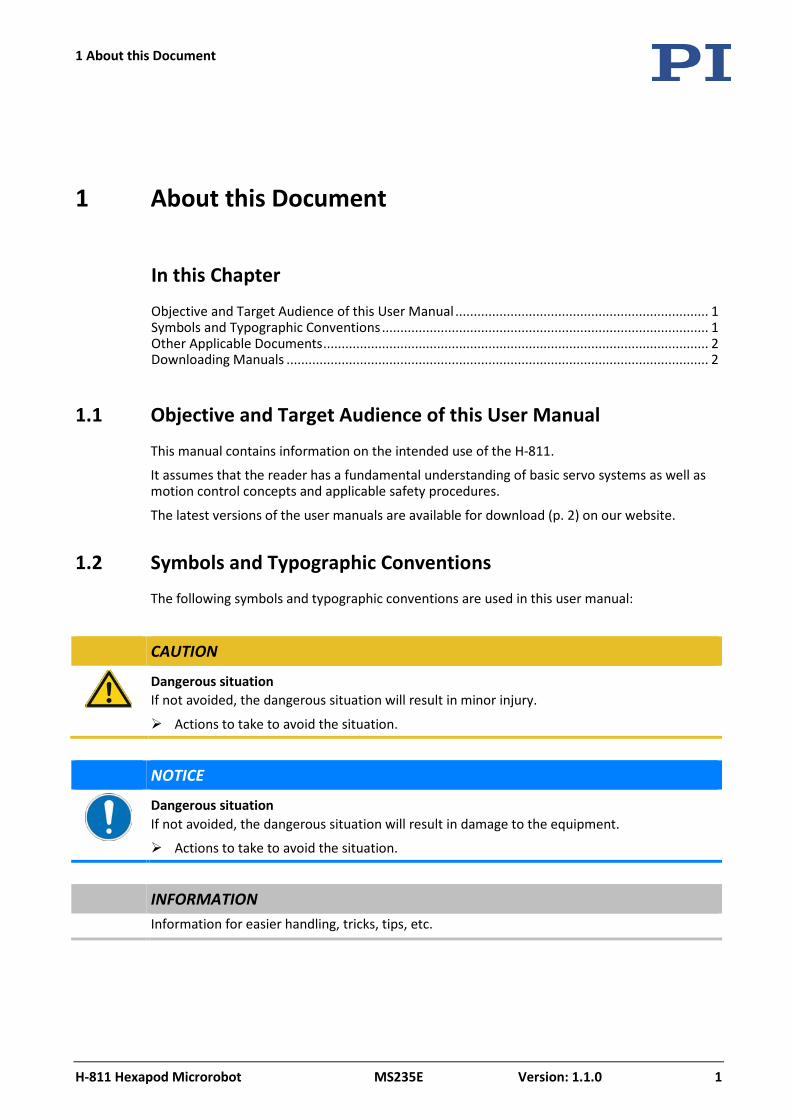
1.1 Objective and Target Audience of this User Manual
This manual contains information on the intended use of the H-811.
It assumes that the reader has a fundamental understanding of basic servo systems as well as motion control concepts and applicable safety procedures.
The latest versions of the user manuals are available for download (p. 2) on our website.
1.2 Symbols and Typographic Conventions
The following symbols and typographic conventions are used in this user manual:
CAUTION
Dangerous situation If not avoided, the dangerous situation will result in minor injury.
Actions to take to avoid the situation.
NOTICE
Dangerous situation If not avoided, the dangerous situation will result in damage to the equipment.
Actions to take to avoid the situation.
INFORMATION Information for easier handling, tricks, tips, etc.
1 About this Document
1 About this Document
2 Version: 1.1.0 MS235E H-811 Hexapod Microrobot
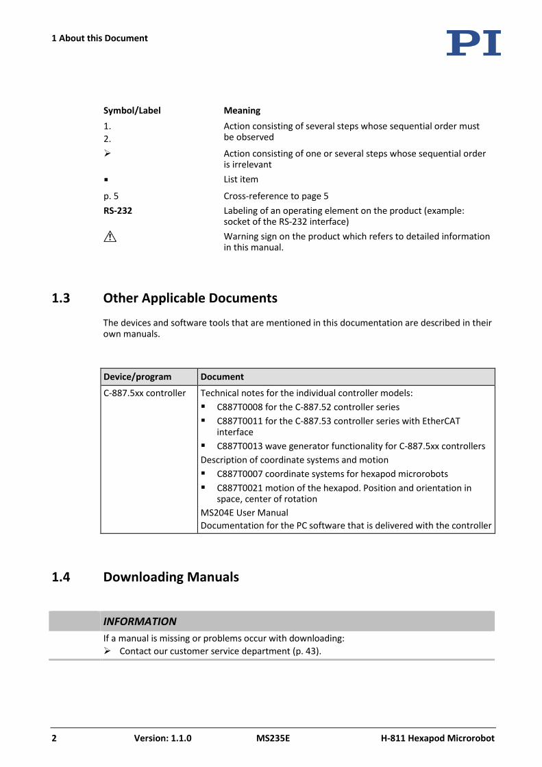
Symbol/Label Meaning 1. 2.
Action consisting of several steps whose sequential order must be observed
Action consisting of one or several steps whose sequential order is irrelevant
List item
p. 5 Cross-reference to page 5 RS-232 Labeling of an operating element on the product (example:
socket of the RS-232 interface)
Warning sign on the product which refers to detailed information in this manual.
1.3 Other Applicable Documents
The devices and software tools that are mentioned in this documentation are described in their own manuals.
Device/program Document
C-887.5xx controller Technical notes for the individual controller models: C887T0008 for the C-887.52 controller series C887T0011 for the C-887.53 controller series with EtherCAT
interface C887T0013 wave generator functionality for C-887.5xx controllers Description of coordinate systems and motion C887T0007 coordinate systems for hexapod microrobots C887T0021 motion of the hexapod. Position and orientation in
space, center of rotation MS204E User Manual Documentation for the PC software that is delivered with the controller
1.4 Downloading Manuals
INFORMATION If a manual is missing or problems occur with downloading:
Contact our customer service department (p. 43).
1 About this Document
H-811 Hexapod Microrobot MS235E Version: 1.1.0 3
INFORMATION For products that are supplied with software (CD in the scope of delivery), access to the
manuals is protected by a password. Protected manuals are only displayed on the website after entering the password. The password is included on the CD of the product.
For products with CD: Identify the password 1. Insert the product CD into the PC drive.
2. Switch to the Manuals directory on the CD.
3. In the Manuals directory, open the Release News (file including releasenews in the file name).
4. Find the user name and the password in the section "User login for software download" in the Release News.
Downloading manuals 1. Open the website www.pi.ws.
2. If access to the manuals is protected by a password:
a) Click Login.
b) Log in with the user name and password.
3. Click Search.
4. Enter the product number up to the period (e.g., P-882) or the product family (e.g., PICMA® Bender) into the search field.
5. Click Start search or press the Enter key.
6. Open the corresponding product detail page in the list of search results:
a) If necessary: Scroll down the list.
b) If necessary: Click Load more results at the end of the list.
c) Click the corresponding product in the list.
7. Scroll down to the Downloads section on the product detail page.
The manuals are displayed under Documentation.
8. Click the desired manual and save it to the hard disk of your PC or to a data storage medium.

2 Safety
H-811 Hexapod Microrobot MS235E Version: 1.1.0 5
In this Chapter
Intended Use .................................................................................................................................. 5 General Safety Instructions............................................................................................................ 5 Organizational Measures ............................................................................................................... 5 Measures for Handling Vacuum-Compatible Products ................................................................. 6
2.1 Intended Use
The hexapod microrobot (short "hexapod") is a laboratory device as defined by DIN EN 61010-1. It is built for indoor use and use in an environment which is free of dirt, oil, and lubricants.
In accordance with its design, the hexapod is intended for positioning, adjusting, and shifting of loads on six axes at various velocities.
The intended use of the hexapod is only possible in conjunction with a suitable controller available from PI (p. 8), which coordinates all motion of the hexapod.
2.2 General Safety Instructions
The H-811 is built according to state-of-the-art technology and recognized safety standards. Improper use can result in personal injury and/or damage to the H-811.
Only use the H-811 for its intended purpose, and only use it if it is in a good working order.
Read the user manual.
Immediately eliminate any faults and malfunctions that are likely to affect safety.
The operator is responsible for the correct installation and operation of the H-811.
2.3 Organizational Measures
User manual Always keep this user manual available with the H-811.
The latest versions of the user manuals are available for download (p. 2) on our website.
2 Safety
2 Safety
6 Version: 1.1.0 MS235E H-811 Hexapod Microrobot
Add all information from the manufacturer to the user manual, for example supplements or technical notes.
If you give the H-811 to other users, also include this user manual as well as other relevant information provided by the manufacturer.
Only use the device on the basis of the complete user manual. Missing information due to an incomplete user manual can result in minor injury and damage to equipment.
Only install and operate the H-811 after you have read and understood this user manual.
Personnel qualification The H-811 may only be installed, started up, operated, maintained, and cleaned by authorized and appropriately qualified personnel.
2.4 Measures for Handling Vacuum-Compatible Products
When handling the vacuum version of the hexapod, attention must be paid to appropriate cleanliness. At PI, all parts are cleaned before assembly. During assembly and measurement, powder-free gloves are worn. Afterwards, the hexapod is cleaned once again by wiping and shrink-wrapped twice in vacuum-compatible film.
Only touch the hexapod with powder-free gloves.
If necessary, wipe the hexapod clean after unpacking.
3 Product Description
H-811 Hexapod Microrobot MS235E Version: 1.1.0 7
In this Chapter
Features and Applications ............................................................................................................. 7 Model Overview ............................................................................................................................. 7 Suitable Controllers ....................................................................................................................... 8 Product View .................................................................................................................................. 9 Scope of Delivery ......................................................................................................................... 10 Technical Features ....................................................................................................................... 11
3.1 Features and Applications
The H-811 hexapod achieves a velocity up to 20 mm/s (vacuum-compatible model: 10 mm/s) and a load capacity of 5 kg in vertical orientation and 2.5 kg in any orientation.
The parallel-kinematic design offers the following advantages:
Positioning operations in six independent axes (three translational axes, three rotational axes) with short settling times
High accuracy and step resolution in all axes
No accumulation of errors of individual axes
No friction and torques from moving cables
The hexapod is controlled with a controller that can be ordered separately from PI (p. 8). The position commands to the controller are entered as Cartesian coordinates.
3.2 Model Overview
Model Designation
H-811.I2 Miniature hexapod microrobot, brushless DC motor, 5 kg load capacity, 20 mm/s velocity, 0.5 m cable length, including 3 m cable set
H-811.I2V Miniature hexapod microrobot, brushless DC motor, vacuum compatible to 10-6 hPa, 5 kg load capacity, 10 mm/s velocity, 2 m cable length, including 3 m cable set and feedthrough
3 Product Description
3 Product Description
8 Version: 1.1.0 MS235E H-811 Hexapod Microrobot
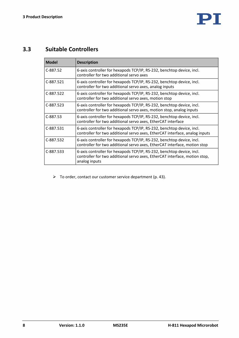
3.3 Suitable Controllers
Model Description
C-887.52 6-axis controller for hexapods TCP/IP, RS-232, benchtop device, incl. controller for two additional servo axes
C-887.521 6-axis controller for hexapods TCP/IP, RS-232, benchtop device, incl. controller for two additional servo axes, analog inputs
C-887.522 6-axis controller for hexapods TCP/IP, RS-232, benchtop device, incl. controller for two additional servo axes, motion stop
C-887.523 6-axis controller for hexapods TCP/IP, RS-232, benchtop device, incl. controller for two additional servo axes, motion stop, analog inputs
C-887.53 6-axis controller for hexapods TCP/IP, RS-232, benchtop device, incl. controller for two additional servo axes, EtherCAT interface
C-887.531 6-axis controller for hexapods TCP/IP, RS-232, benchtop device, incl. controller for two additional servo axes, EtherCAT interface, analog inputs
C-887.532 6-axis controller for hexapods TCP/IP, RS-232, benchtop device, incl. controller for two additional servo axes, EtherCAT interface, motion stop
C-887.533 6-axis controller for hexapods TCP/IP, RS-232, benchtop device, incl. controller for two additional servo axes, EtherCAT interface, motion stop, analog inputs
To order, contact our customer service department (p. 43).
3 Product Description
H-811 Hexapod Microrobot MS235E Version: 1.1.0 9
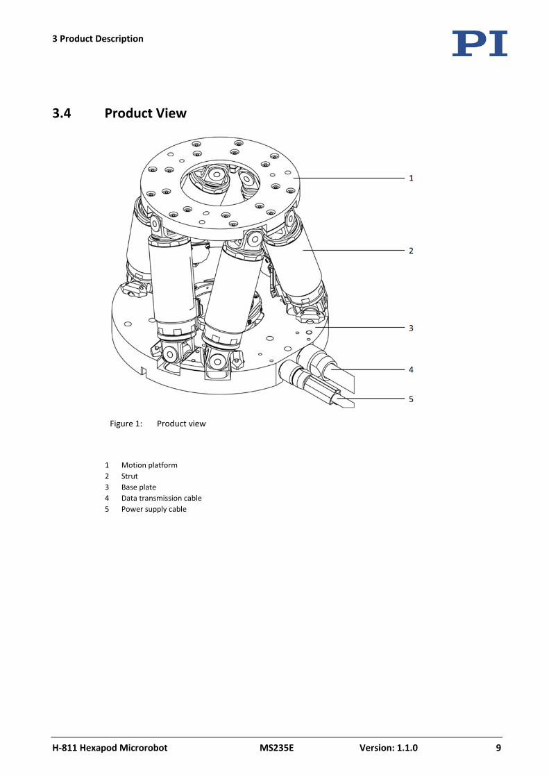
3.4 Product View
Figure 1: Product view
1 Motion platform 2 Strut 3 Base plate 4 Data transmission cable 5 Power supply cable
3 Product Description
10 Version: 1.1.0 MS235E H-811 Hexapod Microrobot
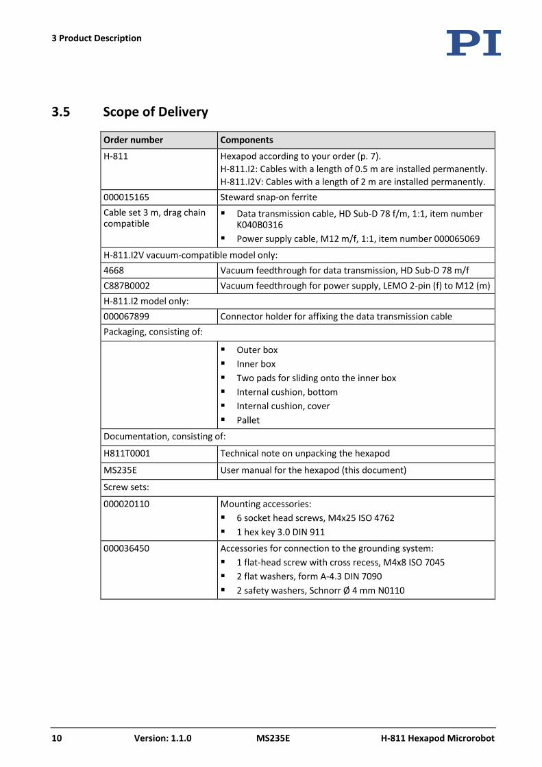
3.5 Scope of Delivery
Order number Components
H-811 Hexapod according to your order (p. 7). H-811.I2: Cables with a length of 0.5 m are installed permanently. H-811.I2V: Cables with a length of 2 m are installed permanently.
000015165 Steward snap-on ferrite Cable set 3 m, drag chain compatible
Data transmission cable, HD Sub-D 78 f/m, 1:1, item number K040B0316
Power supply cable, M12 m/f, 1:1, item number 000065069
H-811.I2V vacuum-compatible model only: 4668 Vacuum feedthrough for data transmission, HD Sub-D 78 m/f C887B0002 Vacuum feedthrough for power supply, LEMO 2-pin (f) to M12 (m) H-811.I2 model only: 000067899 Connector holder for affixing the data transmission cable Packaging, consisting of:
Outer box Inner box Two pads for sliding onto the inner box Internal cushion, bottom Internal cushion, cover Pallet
Documentation, consisting of:
H811T0001 Technical note on unpacking the hexapod
MS235E User manual for the hexapod (this document)
Screw sets:
000020110 Mounting accessories: 6 socket head screws, M4x25 ISO 4762 1 hex key 3.0 DIN 911
000036450 Accessories for connection to the grounding system: 1 flat-head screw with cross recess, M4x8 ISO 7045 2 flat washers, form A-4.3 DIN 7090 2 safety washers, Schnorr Ø 4 mm N0110
3 Product Description
H-811 Hexapod Microrobot MS235E Version: 1.1.0 11
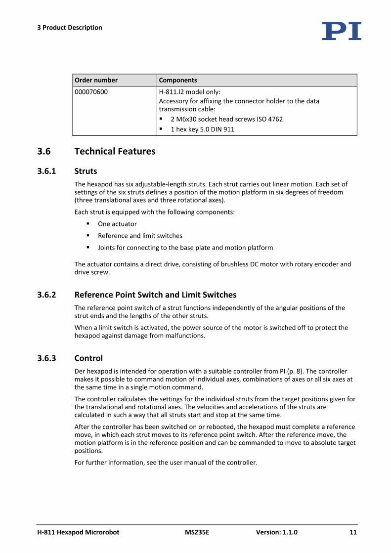
Order number Components
000070600 H-811.I2 model only: Accessory for affixing the connector holder to the data transmission cable: 2 M6x30 socket head screws ISO 4762 1 hex key 5.0 DIN 911
3.6 Technical Features
3.6.1 Struts The hexapod has six adjustable-length struts. Each strut carries out linear motion. Each set of settings of the six struts defines a position of the motion platform in six degrees of freedom (three translational axes and three rotational axes).
Each strut is equipped with the following components:
One actuator
Reference and limit switches
Joints for connecting to the base plate and motion platform
The actuator contains a direct drive, consisting of brushless DC motor with rotary encoder and drive screw.
3.6.2 Reference Point Switch and Limit Switches The reference point switch of a strut functions independently of the angular positions of the strut ends and the lengths of the other struts.
When a limit switch is activated, the power source of the motor is switched off to protect the hexapod against damage from malfunctions.
3.6.3 Control Der hexapod is intended for operation with a suitable controller from PI (p. 8). The controller makes it possible to command motion of individual axes, combinations of axes or all six axes at the same time in a single motion command.
The controller calculates the settings for the individual struts from the target positions given for the translational and rotational axes. The velocities and accelerations of the struts are calculated in such a way that all struts start and stop at the same time.
After the controller has been switched on or rebooted, the hexapod must complete a reference move, in which each strut moves to its reference point switch. After the reference move, the motion platform is in the reference position and can be commanded to move to absolute target positions.
For further information, see the user manual of the controller.
3 Product Description
12 Version: 1.1.0 MS235E H-811 Hexapod Microrobot
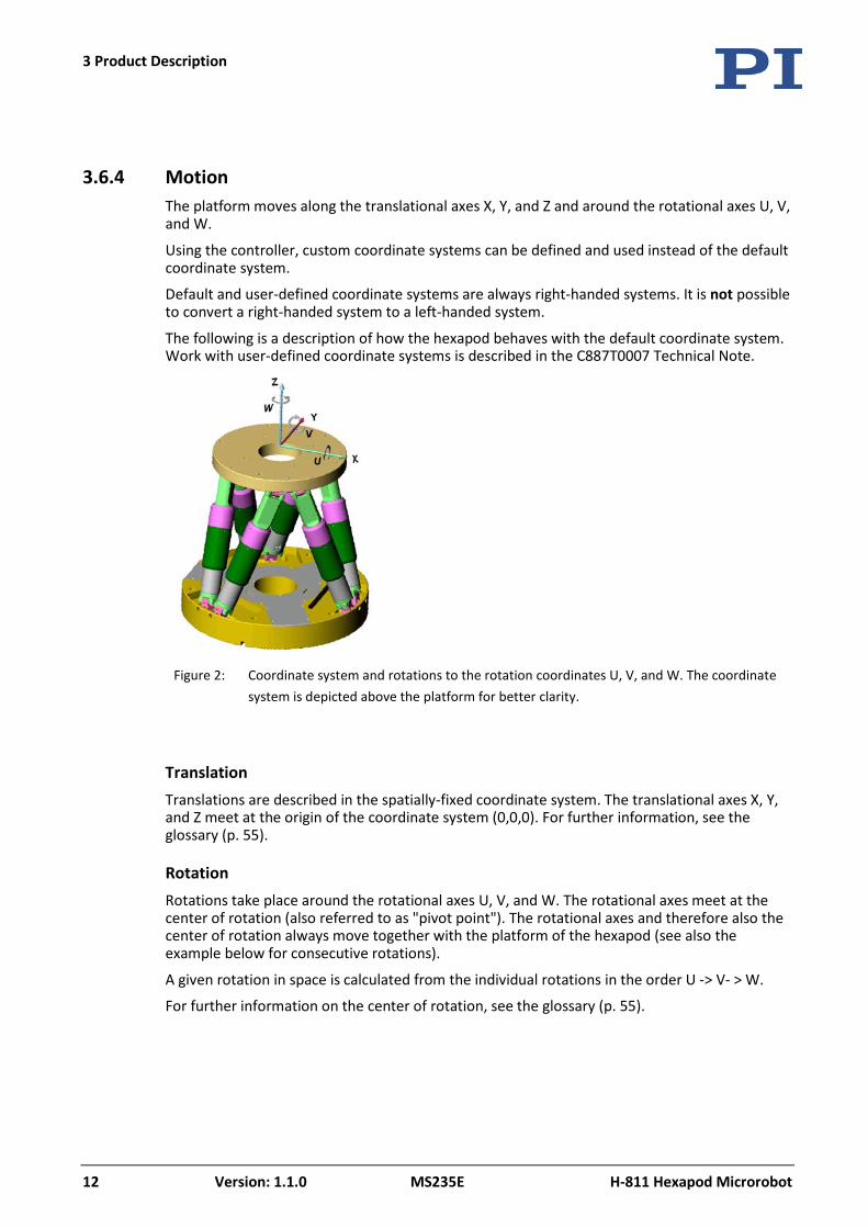
3.6.4 Motion The platform moves along the translational axes X, Y, and Z and around the rotational axes U, V, and W.
Using the controller, custom coordinate systems can be defined and used instead of the default coordinate system.
Default and user-defined coordinate systems are always right-handed systems. It is not possible to convert a right-handed system to a left-handed system.
The following is a description of how the hexapod behaves with the default coordinate system. Work with user-defined coordinate systems is described in the C887T0007 Technical Note.
Figure 2: Coordinate system and rotations to the rotation coordinates U, V, and W. The coordinate
system is depicted above the platform for better clarity.
Translation Translations are described in the spatially-fixed coordinate system. The translational axes X, Y, and Z meet at the origin of the coordinate system (0,0,0). For further information, see the glossary (p. 55).
Rotation Rotations take place around the rotational axes U, V, and W. The rotational axes meet at the center of rotation (also referred to as "pivot point"). The rotational axes and therefore also the center of rotation always move together with the platform of the hexapod (see also the example below for consecutive rotations).
A given rotation in space is calculated from the individual rotations in the order U -> V- > W.
For further information on the center of rotation, see the glossary (p. 55).
3 Product Description
H-811 Hexapod Microrobot MS235E Version: 1.1.0 13
INFORMATION
The dimensional drawing (p. 49) contains the following: Orientation of the default coordinate system Position of the center of rotation after the reference move, when the default settings of
the controller are used
Example: Consecutive rotations
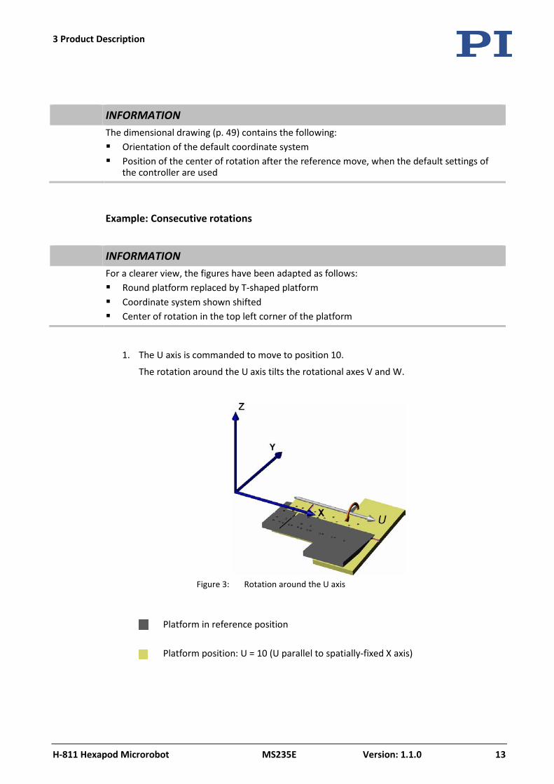
INFORMATION For a clearer view, the figures have been adapted as follows:
Round platform replaced by T-shaped platform Coordinate system shown shifted Center of rotation in the top left corner of the platform
1. The U axis is commanded to move to position 10.
The rotation around the U axis tilts the rotational axes V and W.
Figure 3: Rotation around the U axis
Platform in reference position
Platform position: U = 10 (U parallel to spatially-fixed X axis)
3 Product Description
14 Version: 1.1.0 MS235E H-811 Hexapod Microrobot
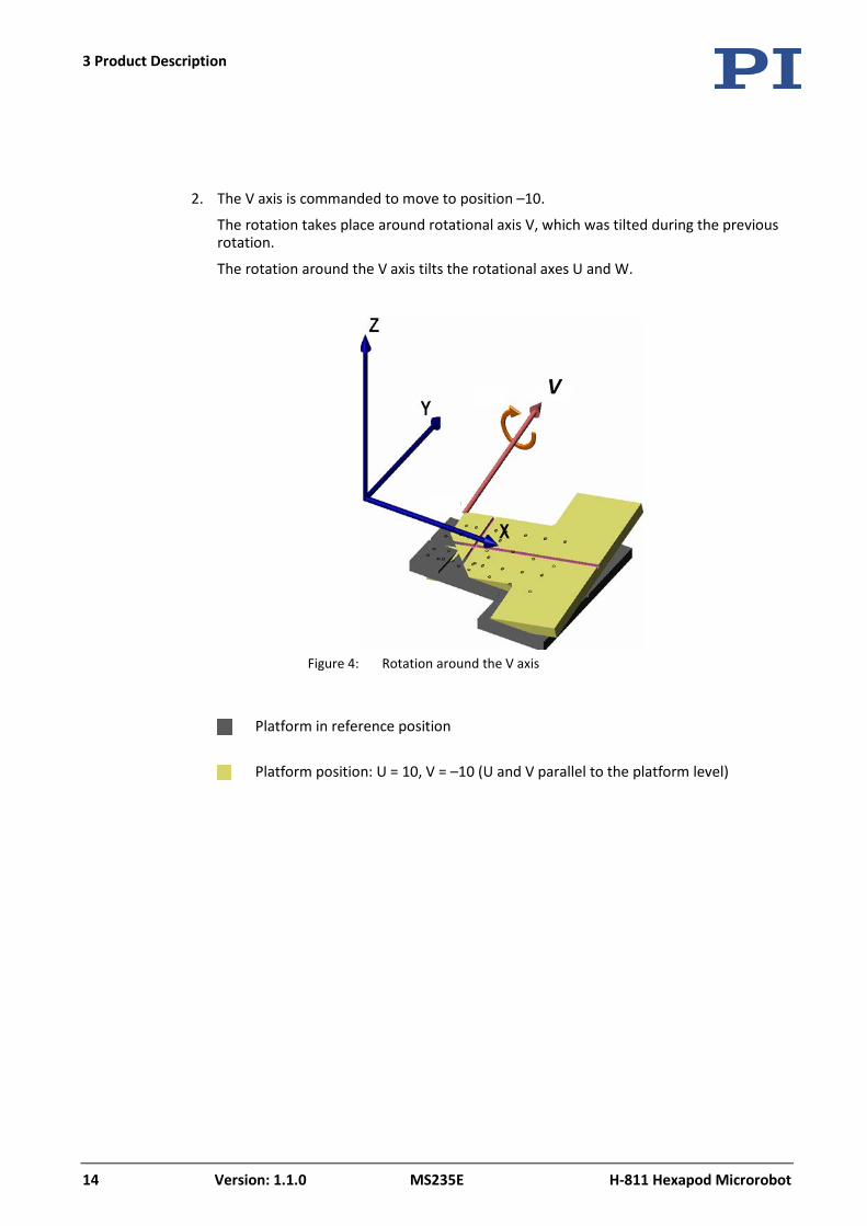
2. The V axis is commanded to move to position –10.
The rotation takes place around rotational axis V, which was tilted during the previous rotation.
The rotation around the V axis tilts the rotational axes U and W.
Figure 4: Rotation around the V axis
Platform in reference position
Platform position: U = 10, V = –10 (U and V parallel to the platform level)
3 Product Description
H-811 Hexapod Microrobot MS235E Version: 1.1.0 15
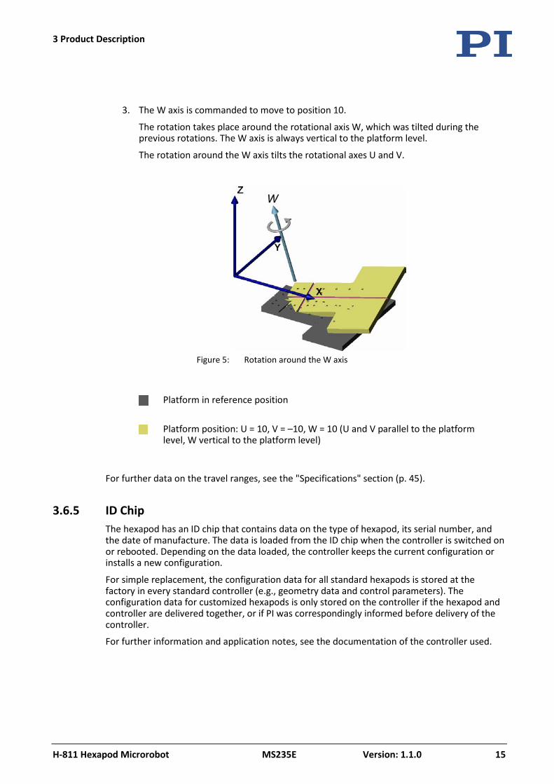
3. The W axis is commanded to move to position 10.
The rotation takes place around the rotational axis W, which was tilted during the previous rotations. The W axis is always vertical to the platform level.
The rotation around the W axis tilts the rotational axes U and V.
Figure 5: Rotation around the W axis
Platform in reference position
Platform position: U = 10, V = –10, W = 10 (U and V parallel to the platform level, W vertical to the platform level)
For further data on the travel ranges, see the "Specifications" section (p. 45).
3.6.5 ID Chip The hexapod has an ID chip that contains data on the type of hexapod, its serial number, and the date of manufacture. The data is loaded from the ID chip when the controller is switched on or rebooted. Depending on the data loaded, the controller keeps the current configuration or installs a new configuration.
For simple replacement, the configuration data for all standard hexapods is stored at the factory in every standard controller (e.g., geometry data and control parameters). The configuration data for customized hexapods is only stored on the controller if the hexapod and controller are delivered together, or if PI was correspondingly informed before delivery of the controller.
For further information and application notes, see the documentation of the controller used.

4 Unpacking
H-811 Hexapod Microrobot MS235E Version: 1.1.0 17
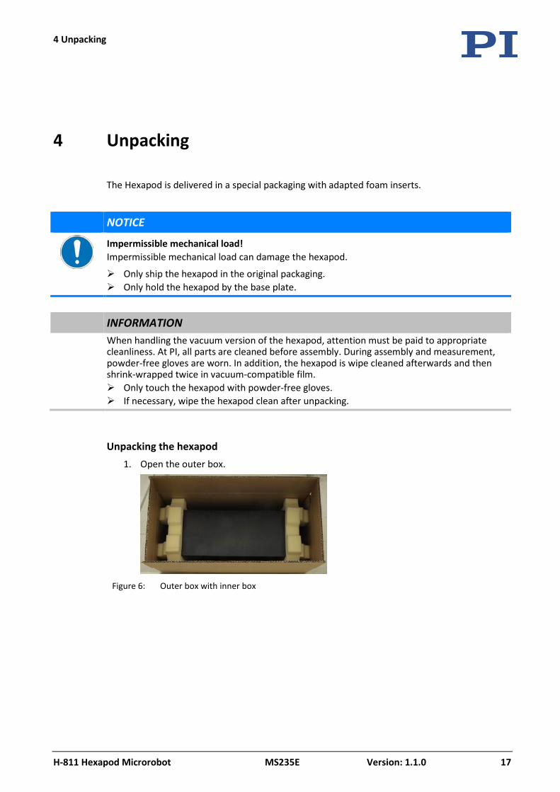
The Hexapod is delivered in a special packaging with adapted foam inserts.
NOTICE
Impermissible mechanical load! Impermissible mechanical load can damage the hexapod.
Only ship the hexapod in the original packaging. Only hold the hexapod by the base plate.
INFORMATION When handling the vacuum version of the hexapod, attention must be paid to appropriate
cleanliness. At PI, all parts are cleaned before assembly. During assembly and measurement, powder-free gloves are worn. In addition, the hexapod is wipe cleaned afterwards and then shrink-wrapped twice in vacuum-compatible film. Only touch the hexapod with powder-free gloves. If necessary, wipe the hexapod clean after unpacking.
Unpacking the hexapod 1. Open the outer box.
Figure 6: Outer box with inner box
4 Unpacking
4 Unpacking
18 Version: 1.1.0 MS235E H-811 Hexapod Microrobot
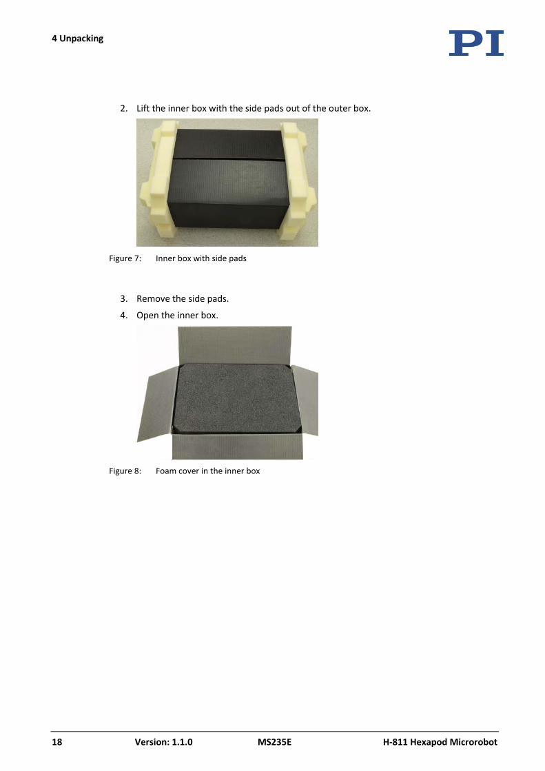
2. Lift the inner box with the side pads out of the outer box.
Figure 7: Inner box with side pads
3. Remove the side pads.
4. Open the inner box.
Figure 8: Foam cover in the inner box
4 Unpacking
H-811 Hexapod Microrobot MS235E Version: 1.1.0 19
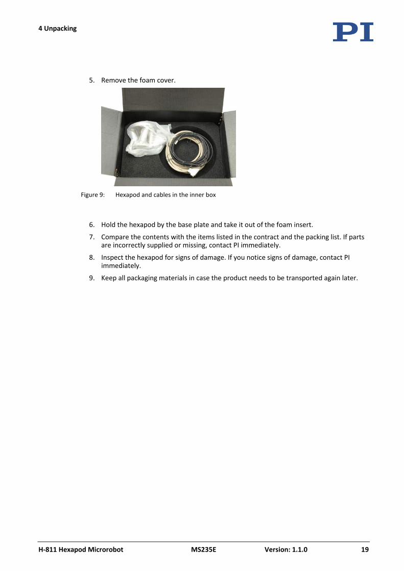
5. Remove the foam cover.
Figure 9: Hexapod and cables in the inner box
6. Hold the hexapod by the base plate and take it out of the foam insert.
7. Compare the contents with the items listed in the contract and the packing list. If parts are incorrectly supplied or missing, contact PI immediately.
8. Inspect the hexapod for signs of damage. If you notice signs of damage, contact PI immediately.
9. Keep all packaging materials in case the product needs to be transported again later.


5 Installation
H-811 Hexapod Microrobot MS235E Version: 1.1.0 21
In this Chapter
General Notes on Installation ...................................................................................................... 21 Determining the Permissible Load and Workspace ..................................................................... 22 Attaching the Snap-on Ferrite...................................................................................................... 23 Grounding the Hexapod ............................................................................................................... 24 H-811.I2: Affixing the Data Transmission Cable with the Connector Holder .............................. 25 Mounting the Hexapod on a Surface ........................................................................................... 26 Affixing the Load to the Hexapod ................................................................................................ 27 Connecting the Hexapod to the Controller.................................................................................. 28
5.1 General Notes on Installation
The hexapod can be mounted in any orientation.
NOTICE
Impermissible mechanical load and collisions! Impermissible mechanical load and collisions between the hexapod, the load to be moved, and the surroundings can damage the hexapod.
Only hold the hexapod by the base plate. Before installing the load, determine the limit value for the load of the hexapod with a
simulation program (p. 22). The limit values determined with the simulation program are only valid when the controller has the servo mode switched on for the axes of the motion platform of the connected hexapod.
Before installing the load, determine the workspace of the hexapod with a simulation program (p. 22). The limits of the workspace vary depending on the current position of the hexapod (translational and rotational coordinates), from the enabled coordinate system and the current coordinates of the center of rotation.
Avoid high forces and torques on the motion platform during installation. Ensure an uninterruptible power supply in order to prevent an unintentional deactivation
of the hexapod system and resulting unintentional position changes of the hexapod. Make sure that no collisions between the hexapod, the load to be moved, and the
surroundings are possible in the workspace of the hexapod.
5 Installation
5 Installation
22 Version: 1.1.0 MS235E H-811 Hexapod Microrobot
INFORMATION The optionally available PIVeriMove software for collision checking can be used to
mathematically check possible collisions between the hexapod, the load and the surroundings. The use of the software is recommended when the hexapod is located in a limited installation space and/or operated with a spatially limiting load. For details regarding the activation and configuration of the PIVeriMove software for collision checking, see C887T0002 Technical Note (included in the scope of delivery of the software).
5.2 Determining the Permissible Load and Workspace
Tools and accessories PC with Windows operating system, on which the program Hexapod Simulation
Software is installed. For further information, see the user manual of the controller.
Determining the workspace and the permissible load of the hexapod Follow the instructions in the manual of the controller to determine the workspace and
the limit value for the load of the hexapod with the simulation program.
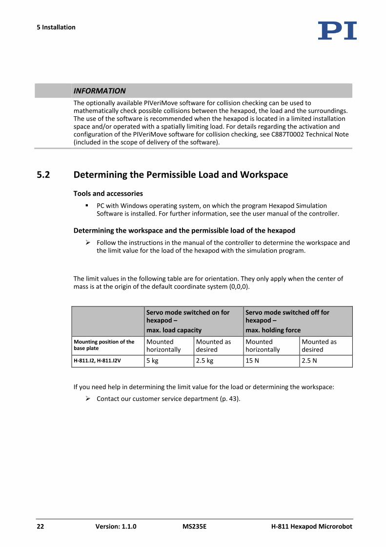
The limit values in the following table are for orientation. They only apply when the center of mass is at the origin of the default coordinate system (0,0,0).
Servo mode switched on for hexapod – max. load capacity
Servo mode switched off for hexapod – max. holding force
Mounting position of the base plate
Mounted horizontally
Mounted as desired
Mounted horizontally
Mounted as desired
H-811.I2, H-811.I2V 5 kg 2.5 kg 15 N 2.5 N
If you need help in determining the limit value for the load or determining the workspace:
Contact our customer service department (p. 43).
5 Installation
H-811 Hexapod Microrobot MS235E Version: 1.1.0 23
5.3 Attaching the Snap-on Ferrite
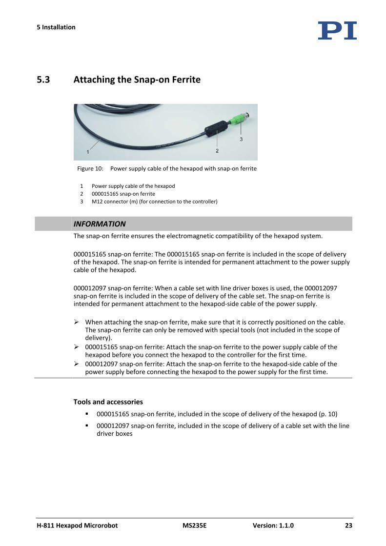
Figure 10: Power supply cable of the hexapod with snap-on ferrite
1 Power supply cable of the hexapod 2 000015165 snap-on ferrite 3 M12 connector (m) (for connection to the controller)
INFORMATION The snap-on ferrite ensures the electromagnetic compatibility of the hexapod system.
000015165 snap-on ferrite: The 000015165 snap-on ferrite is included in the scope of delivery of the hexapod. The snap-on ferrite is intended for permanent attachment to the power supply cable of the hexapod. 000012097 snap-on ferrite: When a cable set with line driver boxes is used, the 000012097 snap-on ferrite is included in the scope of delivery of the cable set. The snap-on ferrite is intended for permanent attachment to the hexapod-side cable of the power supply. When attaching the snap-on ferrite, make sure that it is correctly positioned on the cable.
The snap-on ferrite can only be removed with special tools (not included in the scope of delivery).
000015165 snap-on ferrite: Attach the snap-on ferrite to the power supply cable of the hexapod before you connect the hexapod to the controller for the first time.
000012097 snap-on ferrite: Attach the snap-on ferrite to the hexapod-side cable of the power supply before connecting the hexapod to the power supply for the first time.
Tools and accessories 000015165 snap-on ferrite, included in the scope of delivery of the hexapod (p. 10)
000012097 snap-on ferrite, included in the scope of delivery of a cable set with the line driver boxes
5 Installation
24 Version: 1.1.0 MS235E H-811 Hexapod Microrobot
Permanently attaching the snap-on ferrite 1. 000015165 snap-on ferrite:
Put the power supply cable of the hexapod into the open snap-on ferrite close to and behind the M12 connector (m) that is intended for connection to the controller (see figure). 000012097 snap-on ferrite: Put the hexapod-side cable of the power supply into the open snap-on ferrite approx. 10 to 15 cm behind the power supply (without figure).
2. Close the snap-on ferrite:
a) Align the cable so that it is not squeezed when the snap-on ferrite is closed.
b) Carefully press the two halves of the snap-on ferrite around the cable until the lock engages.
5.4 Grounding the Hexapod
The hexapod is not grounded via the power supply cable. If a functional grounding is required for potential equalization:
1. Connect the base plate to the grounding system:
− For connection, use the supplied accessories (p. 10) and the M4 hole with an 8 mm depth marked with the ground connection symbol (p. 49).
2. Connect the motion platform to the grounding system:
− Use one of the mounting holes in the motion platform (p. 49) for connection. or
− If the motion platform and the load are connected conductively to each other, connect the load to the grounding system.
5 Installation
H-811 Hexapod Microrobot MS235E Version: 1.1.0 25
5.5 H-811.I2: Affixing the Data Transmission Cable with the Connector Holder
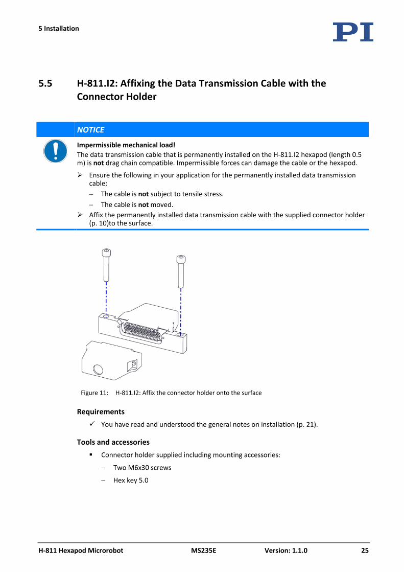
NOTICE
Impermissible mechanical load! The data transmission cable that is permanently installed on the H-811.I2 hexapod (length 0.5 m) is not drag chain compatible. Impermissible forces can damage the cable or the hexapod.
Ensure the following in your application for the permanently installed data transmission cable: − The cable is not subject to tensile stress. − The cable is not moved.
Affix the permanently installed data transmission cable with the supplied connector holder (p. 10)to the surface.
Figure 11: H-811.I2: Affix the connector holder onto the surface
Requirements You have read and understood the general notes on installation (p. 21).
Tools and accessories Connector holder supplied including mounting accessories:
− Two M6x30 screws
− Hex key 5.0
5 Installation
26 Version: 1.1.0 MS235E H-811 Hexapod Microrobot
Affixing the data transmission cable with connector holder 1. Attach the connector holder to the HD Sub-D 78 connector (m) of the data transmission
cable that is permanently installed on the H-811.I2 hexapod:
a) Remove both hexagonal nuts from the screws of the connector.
b) Affix the connector to the connector holder with the screws.
2. Drill two M6 threaded holes into the surface for mounting with M6x30 screws:
− Pay attention to the arrangement of the two mounting holes in the connector holder, see dimensional drawing (p. 49).
− Put the connector holder on the surface so that the data transmission cable that is permanently installed on the hexapod, is not moved in your application and is not subject to tensile stress.
3. Affix the connector holder on the surface with the screws supplied.
The free side of the connector holder is intended to connect the drag chain-compatible data transmission cable (included in the cable set of the H-811.I2). For further information, see "Connecting the Hexapod to the Controller" (p. 28).
5.6 Mounting the Hexapod on a Surface
NOTICE
Impermissible mechanical load! An impermissible mechanical load can damage the hexapod.
Only hold the hexapod by the base plate.
NOTICE
Warping of the base plate! Incorrect mounting can warp the base plate. Warping of the base plate reduces the accuracy.
Mount the hexapod on an even surface. The recommended flatness of the surface is 200 µm.
Requirements You have read and understood the general notes on installation (p. 21).
Tools and accessories Hex key 3.0 and six of the supplied M4x25 screws (p. 10)
Optional: two locating pins for easy alignment of the hexapod, suitable for holes with Ø 3 mm F7, not included in the scope of delivery
5 Installation
H-811 Hexapod Microrobot MS235E Version: 1.1.0 27
Mounting the hexapod 1. Make the necessary holes in the surface:
− Six M4 threaded holes for mounting with M4x25 screws
− Optional: two locating holes with Ø 3 mm F7 for accommodating locating pins
The arrangement of the six mounting holes as well as the two locating holes in the base plate of the hexapod can be found in the dimensional drawing (p. 49). The locating holes are in the bottom side of the base plate.
2. If you use locating pins to align the hexapod:
a) Insert the locating pins into the locating holes in the hexapod or the surface.
b) Place the hexapod on the surface so that the locating pins are inserted into the corresponding locating holes on the other side.
3. Mount the hexapod on the six mounting holes in the base plate using the included screws.
5.7 Affixing the Load to the Hexapod
NOTICE
Impermissible mechanical load and collisions! Impermissible mechanical load and collisions between the hexapod, the load to be moved, and the surroundings can damage the hexapod.
Make sure that the installed load observes the limit value resulting from the load test (p. 22).
Avoid high forces and torques on the motion platform during installation. Make sure that no collisions between the hexapod, the load to be moved, and the
surroundings are possible in the workspace of the hexapod.
NOTICE
Excessively long screws! The hexapod can be damaged by screws that are inserted too deeply.
When selecting the screw length, observe the thickness of the motion platform or the depth of the mounting holes (p. 49) together with the load to be mounted.
Only use screws that do not project under the motion platform after being screwed in. Only mount the hexapod and the load on the mounting fixtures (holes) intended for this
purpose.

5 Installation
28 Version: 1.1.0 MS235E H-811 Hexapod Microrobot
Requirements You have read and understood the general notes on installation (p. 21).
You have determined the permissible load and the workspace of the hexapod (p. 22).
You have designed the load and the surroundings of the hexapod so that the permissible load of the hexapod is observed and no collisions can occur.
Tools and accessories 3 suitably long M4 screws
Suitable tool for tightening the screws
Optional: two locating pins for easy alignment of the load on the hexapod, suitable for holes with Ø 3 mm F7, not included in the scope of delivery
Affixing the load 1. Align the load so that the selected mounting holes in the motion platform can be used
for affixing it.
If you use locating pins to align the load:
a) Make two locating holes with Ø 3 mm F7 in the load for accommodating locating pins.
b) Insert the locating pins into the locating holes in the motion platform or in the load.
c) Place the load on the motion platform so that the locating pins are inserted into the corresponding locating holes on the other side.
The arrangement of the mounting and locating holes in the motion platform of the hexapod can be found in the dimensional drawing (p. 49).
2. Use the screws to affix the load to the selected mounting holes in the motion platform.
5.8 Connecting the Hexapod to the Controller
A cable set with a length if 3 m is included in the scope of delivery of the hexapod (p. 10). Longer cable sets are available as optional accessory. Cable sets with a length >20 m include line driver boxes (e.g., C-887.5A50 cable set with a length of 50 m).
Vacuum feedthroughs are also included in the scope of delivery of a vacuum-compatible hexapod (p. 10).
5 Installation
H-811 Hexapod Microrobot MS235E Version: 1.1.0 29
NOTICE
Impermissible mechanical load! The data transmission cable that is permanently installed on the H-811.I2 hexapod (length 0.5 m) is not drag chain compatible. Impermissible forces can damage the cable or the hexapod.
Ensure the following in your application for the permanently installed data transmission cable: − The cable is not subject to tensile stress. − The cable is not moved.
Affix the permanently installed data transmission cable with the supplied connector holder (p. 10)to the surface.
NOTICE
Incorrect wiring! When a cable set with line driver boxes is used: Interchanging the cables between the channels of the line drive boxes causes the hexapod not to move or move uncontrollably. Uncontrolled motion of the hexapod can cause collision that can damage the hexapod, the load to be moved or the surroundings. When connecting the line driver boxes, observe the channel assignment that is specified
on the labeling of the sockets and connectors.
INFORMATION
When a cable set with line driver boxes is used: The 24 V Out 7 A connection on the controller is not available for the hexapod because this connection is required for the power supply of the hexapod-side line driver box. A C-887.5PS power supply for the hexapod and a snap-on ferrite (000012097) are therefore included in the scope of delivery of the cable set. Attach the snap-on ferrite to the hexapod-side cable of the power supply (p. 23) before
connecting the hexapod to the power supply for the first time.
Requirements The controller is switched off, i.e., the on/off switch is in the position .
H-811.I2 hexapod: You have affixed the permanently installed data transmission cable to the surface with the connector holder supplied (p. 25).
Tools and accessories Cable set from the scope of delivery of the hexapod (p. 10).
Alternative: Longer cable set available as optional accessory.
If you want to operate a vacuum-compatible hexapod in a vacuum chamber: Suitable tools for installing the vacuum feedthrough
5 Installation
30 Version: 1.1.0 MS235E H-811 Hexapod Microrobot
If necessary: Installing vacuum feedthroughs
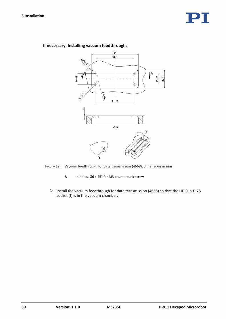
Figure 12: Vacuum feedthrough for data transmission (4668), dimensions in mm
B 4 holes, Ø6 x 45° for M3 countersunk screw
Install the vacuum feedthrough for data transmission (4668) so that the HD Sub-D 78 socket (f) is in the vacuum chamber.
5 Installation
H-811 Hexapod Microrobot MS235E Version: 1.1.0 31
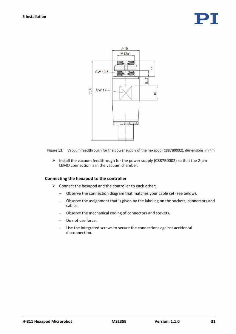
Figure 13: Vacuum feedthrough for the power supply of the hexapod (C887B0002), dimensions in mm
Install the vacuum feedthrough for the power supply (C887B0002) so that the 2-pin LEMO connection is in the vacuum chamber.
Connecting the hexapod to the controller Connect the hexapod and the controller to each other:
− Observe the connection diagram that matches your cable set (see below).
− Observe the assignment that is given by the labeling on the sockets, connectors and cables.
− Observe the mechanical coding of connectors and sockets.
− Do not use force.
− Use the integrated screws to secure the connections against accidental disconnection.
5 Installation
32 Version: 1.1.0 MS235E H-811 Hexapod Microrobot
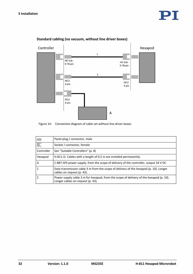
Standard cabling (no vacuum, without line driver boxes)
Figure 14: Connection diagram of cable set without line driver boxes
Panel plug / connector, male
Socket / connector, female
Controller See "Suitable Controllers" (p. 8)
Hexapod H-811.I2. Cables with a length of 0.5 m are installed permanently.
A C-887.5PS power supply, from the scope of delivery of the controller, output 24 V DC
1 Data transmission cable 3 m from the scope of delivery of the hexapod (p. 10). Longer cables on request (p. 43).
2 Power supply cable 3 m for hexapod, from the scope of delivery of the hexapod (p. 10). Longer cables on request (p. 43).
5 Installation
H-811 Hexapod Microrobot MS235E Version: 1.1.0 33
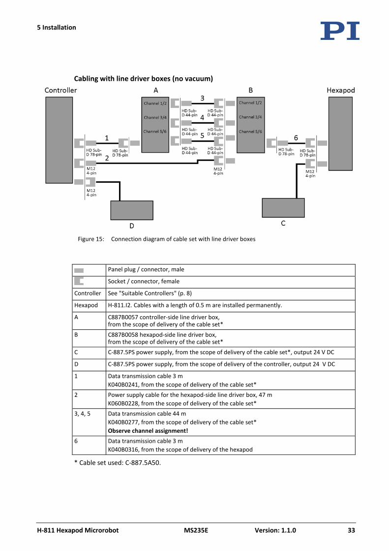
Cabling with line driver boxes (no vacuum)
Figure 15: Connection diagram of cable set with line driver boxes
Panel plug / connector, male
Socket / connector, female
Controller See "Suitable Controllers" (p. 8)
Hexapod H-811.I2. Cables with a length of 0.5 m are installed permanently.
A C887B0057 controller-side line driver box, from the scope of delivery of the cable set*
B C887B0058 hexapod-side line driver box, from the scope of delivery of the cable set*
C C-887.5PS power supply, from the scope of delivery of the cable set*, output 24 V DC
D C-887.5PS power supply, from the scope of delivery of the controller, output 24 V DC
1 Data transmission cable 3 m K040B0241, from the scope of delivery of the cable set*
2 Power supply cable for the hexapod-side line driver box, 47 m K060B0228, from the scope of delivery of the cable set*
3, 4, 5 Data transmission cable 44 m K040B0277, from the scope of delivery of the cable set* Observe channel assignment!
6 Data transmission cable 3 m K040B0316, from the scope of delivery of the hexapod
* Cable set used: C-887.5A50.
5 Installation
34 Version: 1.1.0 MS235E H-811 Hexapod Microrobot
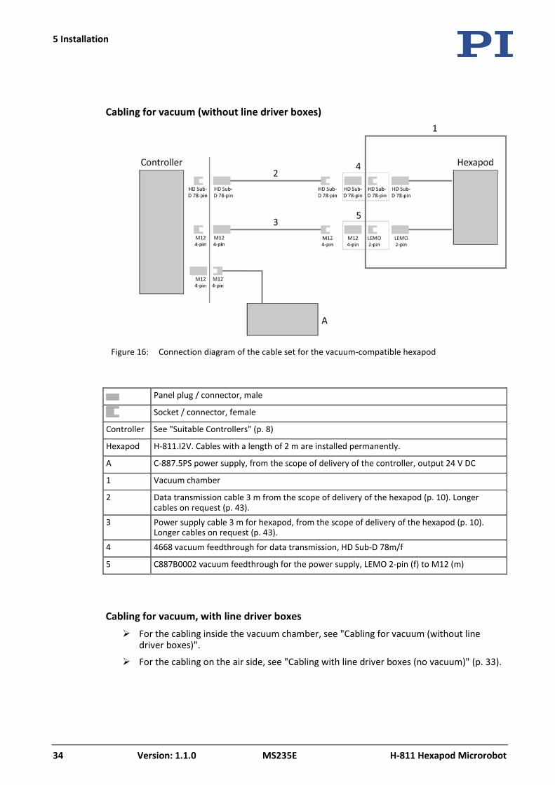
Cabling for vacuum (without line driver boxes)
Figure 16: Connection diagram of the cable set for the vacuum-compatible hexapod
Panel plug / connector, male
Socket / connector, female
Controller See "Suitable Controllers" (p. 8)
Hexapod H-811.I2V. Cables with a length of 2 m are installed permanently.
A C-887.5PS power supply, from the scope of delivery of the controller, output 24 V DC
1 Vacuum chamber
2 Data transmission cable 3 m from the scope of delivery of the hexapod (p. 10). Longer cables on request (p. 43).
3 Power supply cable 3 m for hexapod, from the scope of delivery of the hexapod (p. 10). Longer cables on request (p. 43).
4 4668 vacuum feedthrough for data transmission, HD Sub-D 78m/f
5 C887B0002 vacuum feedthrough for the power supply, LEMO 2-pin (f) to M12 (m)
Cabling for vacuum, with line driver boxes For the cabling inside the vacuum chamber, see "Cabling for vacuum (without line
driver boxes)".
For the cabling on the air side, see "Cabling with line driver boxes (no vacuum)" (p. 33).
6 Startup
H-811 Hexapod Microrobot MS235E Version: 1.1.0 35
In this Chapter
General Notes on Startup ............................................................................................................ 35 Starting Up the Hexapod System ................................................................................................. 36
6.1 General Notes on Startup
CAUTION
Risk of crushing by moving parts! There is a risk of minor injuries from crushing between the moving parts of the hexapod and a stationary part or obstacle. Keep your fingers away from areas where they can get caught by moving parts.
NOTICE
Incorrect configuration of the controller! The configuration data used by the controller (e.g., geometrical data and servo-control parameters) must be adapted to the hexapod. If incorrect configuration data is used, the hexapod can be damaged by uncontrolled motion or collisions. When the controller is switched on or rebooted, the configuration data is adapted using the data that is loaded from the ID chip.
Once you have established communication via TCP/IP or RS-232, send the CST? command. The response shows the hexapod, to which the controller is adapted.
Only operate the hexapod with a controller whose configuration data is adapted to the hexapod.
NOTICE
Damage due to collisions! Collisions can damage the hexapod, the load to be moved, and the surroundings.
Make sure that no collisions are possible between the hexapod, the load to be moved, and the surroundings in the workspace of the hexapod.
Do not place any objects in areas where they can be caught by moving parts. Stop the motion immediately if a controller malfunction occurs.
6 Startup
6 Startup
36 Version: 1.1.0 MS235E H-811 Hexapod Microrobot
NOTICE
Damage from unintentional position changes! The self-locking of the hexapod struts is very low. Although the installed load complies with the limit value resulting from the load test (p. 22), it can trigger an unintentional change in the position of the hexapod if the servo mode or the controller is switched off and in addition, one of the following conditions is met:
The hexapod is not mounted with a horizontally oriented base plate but in any other orientation.
The hexapod is mounted with a horizontally oriented base plate and is not in the reference position.
As a result of unintentional position changes, the actuators in the hexapod struts can be damaged, and collisions between the hexapod, the load to be moved and the surroundings are possible. Collisions can damage the hexapod, the load to be moved or the surroundings.
Support the motion platform or the load appropriately when the servo mode or the controller is switched off.
NOTICE
Heating up of the hexapod in the vacuum! The hexapod heats up during operation in the vacuum.
Allow the heat to dissipate accordingly.
6.2 Starting Up the Hexapod System
Requirements You have read and understood the general notes on startup (p. 35).
You have correctly installed the hexapod, i.e., you have mounted the hexapod onto a surface, affixed the load to the hexapod and connected the hexapod to the controller according to the instructions in "Installation" (p. 21).
You have read and understood the user manual of the controller.
Accessories PC with suitable software (see user manual of the controller)
Starting up the hexapod system 1. Start up the controller (see user manual of the controller).
2. Perform a few motion cycles for testing purposes (see user manual of the controller).
7 Maintenance
H-811 Hexapod Microrobot MS235E Version: 1.1.0 37
In this Chapter
Performing a Maintenance Run ................................................................................................... 37 Packing the Hexapod for Transport ............................................................................................. 37 Cleaning the Hexapod .................................................................................................................. 39
NOTICE
Damage due to improper maintenance! The hexapod can become misaligned as a result of improper maintenance. The specifications can change as a result (p. 45).
Only loosen screws according to the instructions in this manual.
Depending on the operational conditions and the period of use of the hexapod, the following maintenance measures are required.
7.1 Performing a Maintenance Run
Frequent motion over a limited travel range can cause the lubricant to be distributed unevenly on the drive screw.
Perform a maintenance run over the entire travel range at regular intervals (see user manual of the controller). The more often motion is performed over a limited travel range, the shorter the time has to be between the maintenance runs.
7.2 Packing the Hexapod for Transport
NOTICE
Impermissible mechanical load! Impermissible mechanical load can damage the hexapod.
Only ship the hexapod in the original packaging. Only hold the hexapod by the base plate.
7 Maintenance
7 Maintenance
38 Version: 1.1.0 MS235E H-811 Hexapod Microrobot
NOTICE
Damage from applying high forces! Hexapod struts with direct drive can be carefully moved by hand in the case of an error. Blocked struts can be damaged by the use of force.
If one or more struts of the hexapod are blocked, do not move the hexapod by hand. If you move the hexapod by hand, do not use high forces.
NOTICE
Cable break due to excessively bent or crushed cable! A cable break leads to failure of the hexapod.
Pack the hexapod so that the cables are not bent or crushed too much.
Accessories Original packaging (p. 10)
4 cable ties
Packing the hexapod 1. Command a motion of the hexapod to the transport position:
X = Y = Z = U = V = W = 0
2. Uninstall the hexapod system:
a) Remove the load from the motion platform of the hexapod.
b) Switch the controller off.
c) Remove the data transmission cable and the power supply cable from the controller.
d) Loosen all connections between the cables attached permanently to the hexapod and the cable set used, and remove the cables from all attachments (e.g., connector holder of the H-811.I2).
e) Remove the hexapod from the surface.
3. Prepare the cable set for packing.
− Avoid bending the cables.
− Wind up all cables with a diameter of approx. 23 cm and secure them with two cable ties.
4. Wrap the hexapod in a plastic foil to protect it against dirt.
5. Open the outer box.
7 Maintenance
H-811 Hexapod Microrobot MS235E Version: 1.1.0 39
6. Lift the inner box with the side pads out of the outer box.
7. Remove the side pads from the inner box.
8. Open the inner box.
9. Remove the foam cover.
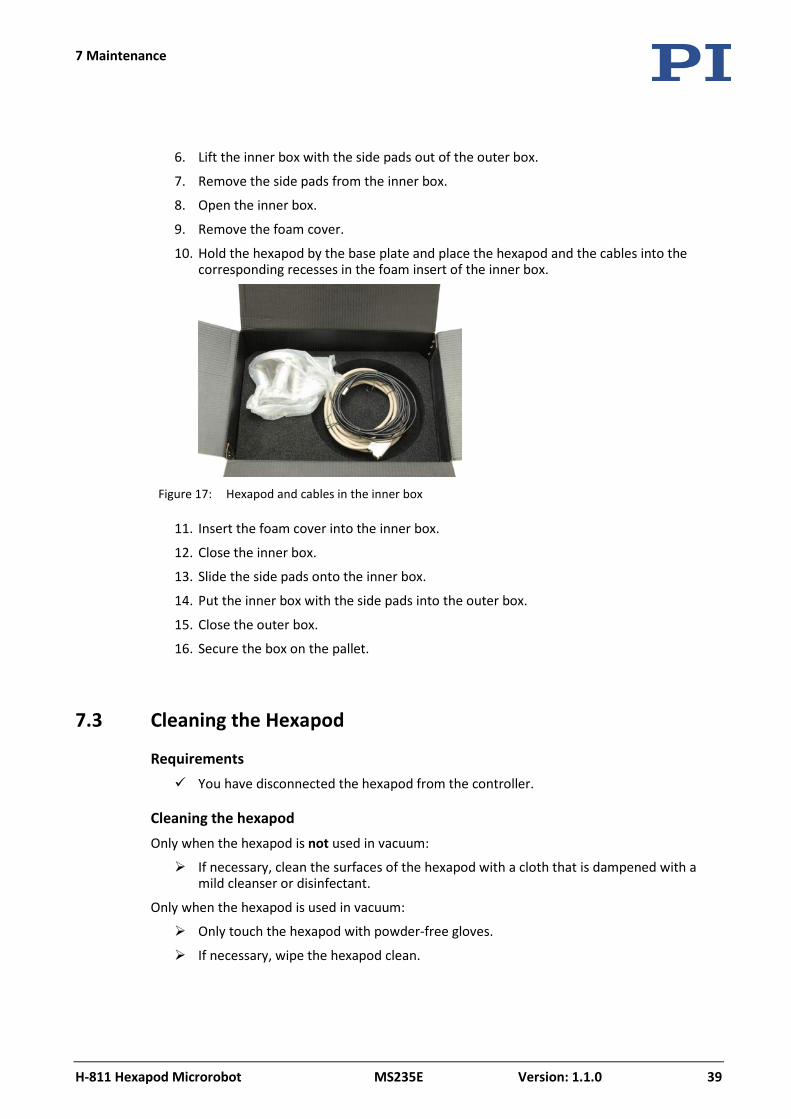
10. Hold the hexapod by the base plate and place the hexapod and the cables into the corresponding recesses in the foam insert of the inner box.
Figure 17: Hexapod and cables in the inner box
11. Insert the foam cover into the inner box.
12. Close the inner box.
13. Slide the side pads onto the inner box.
14. Put the inner box with the side pads into the outer box.
15. Close the outer box.
16. Secure the box on the pallet.
7.3 Cleaning the Hexapod
Requirements You have disconnected the hexapod from the controller.
Cleaning the hexapod Only when the hexapod is not used in vacuum:
If necessary, clean the surfaces of the hexapod with a cloth that is dampened with a mild cleanser or disinfectant.
Only when the hexapod is used in vacuum:
Only touch the hexapod with powder-free gloves.
If necessary, wipe the hexapod clean.

8 Troubleshooting
H-811 Hexapod Microrobot MS235E Version: 1.1.0 41
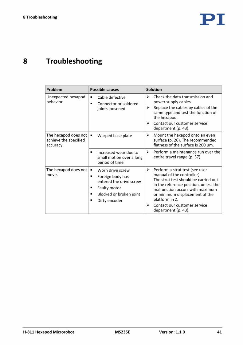
Problem Possible causes Solution
Unexpected hexapod behavior.
Cable defective Connector or soldered
joints loosened
Check the data transmission and power supply cables.
Replace the cables by cables of the same type and test the function of the hexapod.
Contact our customer service department (p. 43).
The hexapod does not achieve the specified accuracy.
Warped base plate Mount the hexapod onto an even surface (p. 26). The recommended flatness of the surface is 200 µm.
Increased wear due to small motion over a long period of time
Perform a maintenance run over the entire travel range (p. 37).
The hexapod does not move.
Worn drive screw Foreign body has
entered the drive screw Faulty motor Blocked or broken joint Dirty encoder
Perform a strut test (see user manual of the controller). The strut test should be carried out in the reference position, unless the malfunction occurs with maximum or minimum displacement of the platform in Z.
Contact our customer service department (p. 43).
8 Troubleshooting
8 Troubleshooting
42 Version: 1.1.0 MS235E H-811 Hexapod Microrobot
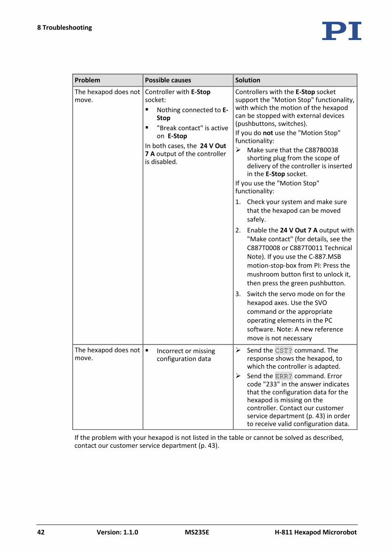
Problem Possible causes Solution
The hexapod does not move.
Controller with E-Stop socket: Nothing connected to E-
Stop "Break contact" is active
on E-Stop In both cases, the 24 V Out 7 A output of the controller is disabled.
Controllers with the E-Stop socket support the "Motion Stop" functionality, with which the motion of the hexapod can be stopped with external devices (pushbuttons, switches). If you do not use the "Motion Stop" functionality: Make sure that the C887B0038
shorting plug from the scope of delivery of the controller is inserted in the E-Stop socket.
If you use the "Motion Stop" functionality: 1. Check your system and make sure
that the hexapod can be moved safely.
2. Enable the 24 V Out 7 A output with "Make contact" (for details, see the C887T0008 or C887T0011 Technical Note). If you use the C-887.MSB motion-stop-box from PI: Press the mushroom button first to unlock it, then press the green pushbutton.
3. Switch the servo mode on for the hexapod axes. Use the SVO command or the appropriate operating elements in the PC software. Note: A new reference move is not necessary
The hexapod does not move.
Incorrect or missing configuration data
Send the CST? command. The response shows the hexapod, to which the controller is adapted.
Send the ERR? command. Error code "233" in the answer indicates that the configuration data for the hexapod is missing on the controller. Contact our customer service department (p. 43) in order to receive valid configuration data.
If the problem with your hexapod is not listed in the table or cannot be solved as described, contact our customer service department (p. 43).

9 Customer Service
H-811 Hexapod Microrobot MS235E Version: 1.1.0 43
For inquiries and orders, contact your PI sales engineer or send us an email (mailto:[email protected]).
If you have questions concerning your system, have the following information ready:
− Product and serial numbers of all products in the system
− Firmware version of the controller (if available)
− Version of the driver or the software (if available)
− Operating system on the PC (if available)
If possible: Take photographs or make videos of your system that can be sent to our customer service department if requested.
The latest versions of the user manuals are available for download (p. 2) on our website.
9 Customer Service

10 Technical Data
H-811 Hexapod Microrobot MS235E Version: 1.1.0 45
In this Chapter
Specifications ............................................................................................................................... 45 Drag Chain Compatible Cables ..................................................................................................... 47 Ambient Conditions and Classifications ....................................................................................... 48 Dimensions .................................................................................................................................. 49 Pin Assignment ............................................................................................................................ 50
10.1 Specifications
10.1.1 Data Table
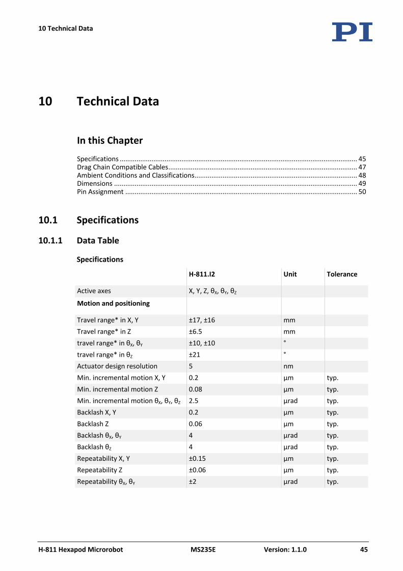
Specifications
H-811.I2 Unit Tolerance
Active axes X, Y, Z, θX, θY, θZ
Motion and positioning
Travel range* in X, Y ±17, ±16 mm Travel range* in Z ±6.5 mm travel range* in θX, θY ±10, ±10 ° travel range* in θZ ±21 ° Actuator design resolution 5 nm Min. incremental motion X, Y 0.2 µm typ. Min. incremental motion Z 0.08 µm typ. Min. incremental motion θX, θY, θZ 2.5 µrad typ. Backlash X, Y 0.2 µm typ. Backlash Z 0.06 µm typ. Backlash θX, θY 4 µrad typ. Backlash θZ 4 µrad typ. Repeatability X, Y ±0.15 µm typ. Repeatability Z ±0.06 µm typ. Repeatability θX, θY ±2 µrad typ.
10 Technical Data
10 Technical Data
46 Version: 1.1.0 MS235E H-811 Hexapod Microrobot
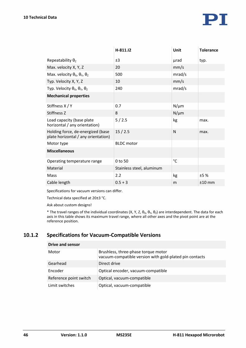
H-811.I2 Unit Tolerance
Repeatability θZ ±3 µrad typ. Max. velocity X, Y, Z 20 mm/s Max. velocity θX, θY, θZ 500 mrad/s Typ. Velocity X, Y, Z 10 mm/s Typ. Velocity θX, θY, θZ 240 mrad/s
Mechanical properties
Stiffness X / Y 0.7 N/µm Stiffness Z 8 N/µm Load capacity (base plate horizontal / any orientation)
5 / 2.5 kg max.
Holding force, de-energized (base plate horizontal / any orientation)
15 / 2.5 N max.
Motor type BLDC motor
Miscellaneous
Operating temperature range 0 to 50 °C Material Stainless steel, aluminum
Mass 2.2 kg ±5 % Cable length 0.5 + 3 m ±10 mm
Specifications for vacuum versions can differ.
Technical data specified at 20±3 °C.
Ask about custom designs!
* The travel ranges of the individual coordinates (X, Y, Z, θX, θY, θZ) are interdependent. The data for each axis in this table shows its maximum travel range, where all other axes and the pivot point are at the reference position.
10.1.2 Specifications for Vacuum-Compatible Versions Drive and sensor
Motor Brushless, three-phase torque motor vacuum-compatible version with gold-plated pin contacts
Gearhead Direct drive
Encoder Optical encoder, vacuum-compatible
Reference point switch Optical, vacuum-compatible
Limit switches Optical, vacuum-compatible
10 Technical Data
H-811 Hexapod Microrobot MS235E Version: 1.1.0 47
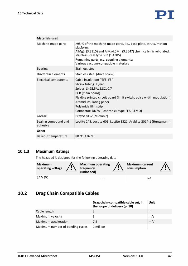
Materials used Machine-made parts >95 % of the machine-made parts, i.e., base plate, struts, motion
platform: AlMgSi (3.2315) and AlMg4.5Mn (3.3547) chemically nickel-plated, stainless steel type 303 (1.4305) Remaining parts, e.g. coupling elements: Various vacuum-compatible materials
Bearing Stainless steel
Drivetrain elements Stainless steel (drive screw)
Electrical components Cable insulation: PTFE, FEP Shrink tubing: Kynar Solder: Sn95.5Ag3.8Cu0.7 PCB (main board) Flexible printed circuit board (limit switch, pulse width modulation) Aramid insulating paper Polyimide film strip Connector: DD78 (Positronic), type FFA (LEMO)
Grease Brayco 815Z (Micronic)
Sealing compound and adhesive
Loctite 243, Loctite 603, Loctite 3321, Araldite 2014-1 (Huntsmann)
Other Bakeout temperature 80 °C (176 °F)
10.1.3 Maximum Ratings The hexapod is designed for the following operating data:
Maximum operating voltage
Maximum operating frequency (unloaded)
Maximum current consumption
24 V DC 5 A
10.2 Drag Chain Compatible Cables
Drag chain-compatible cable set, in the scope of delivery (p. 10)
Unit
Cable length 3 m Maximum velocity 3 m/s Maximum acceleration 7.5 m/s2 Maximum number of bending cycles 1 million
10 Technical Data
48 Version: 1.1.0 MS235E H-811 Hexapod Microrobot
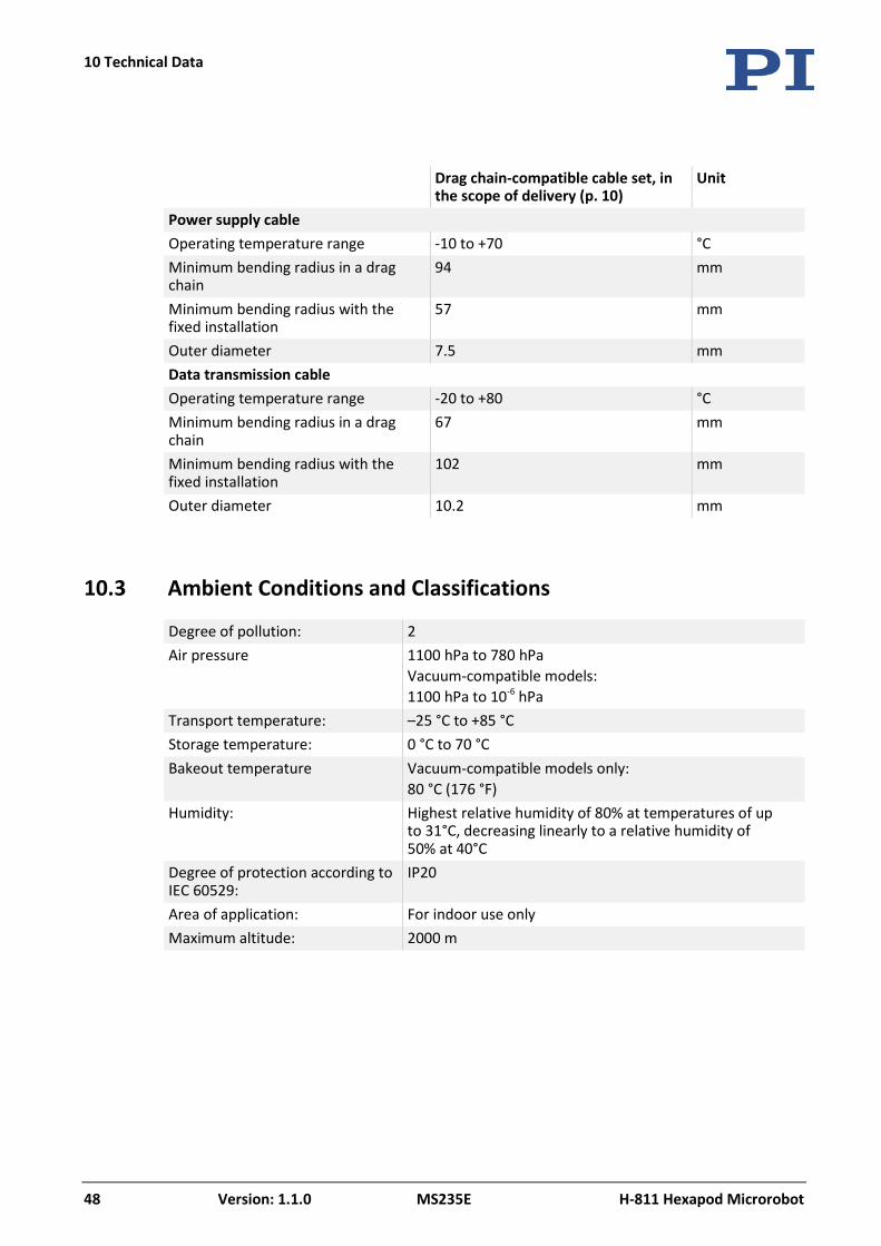
Drag chain-compatible cable set, in the scope of delivery (p. 10)
Unit
Power supply cable Operating temperature range -10 to +70 °C Minimum bending radius in a drag chain
94 mm
Minimum bending radius with the fixed installation
57 mm
Outer diameter 7.5 mm Data transmission cable Operating temperature range -20 to +80 °C Minimum bending radius in a drag chain
67 mm
Minimum bending radius with the fixed installation
102 mm
Outer diameter 10.2 mm
10.3 Ambient Conditions and Classifications
Degree of pollution: 2 Air pressure 1100 hPa to 780 hPa
Vacuum-compatible models: 1100 hPa to 10-6 hPa
Transport temperature: –25 °C to +85 °C Storage temperature: 0 °C to 70 °C Bakeout temperature Vacuum-compatible models only:
80 °C (176 °F) Humidity: Highest relative humidity of 80% at temperatures of up
to 31°C, decreasing linearly to a relative humidity of 50% at 40°C
Degree of protection according to IEC 60529:
IP20
Area of application: For indoor use only Maximum altitude: 2000 m
10 Technical Data
H-811 Hexapod Microrobot MS235E Version: 1.1.0 49
10.4 Dimensions
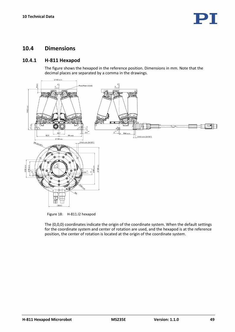
10.4.1 H-811 Hexapod The figure shows the hexapod in the reference position. Dimensions in mm. Note that the decimal places are separated by a comma in the drawings.
Figure 18: H-811.I2 hexapod
The (0,0,0) coordinates indicate the origin of the coordinate system. When the default settings for the coordinate system and center of rotation are used, and the hexapod is at the reference position, the center of rotation is located at the origin of the coordinate system.
10 Technical Data
50 Version: 1.1.0 MS235E H-811 Hexapod Microrobot
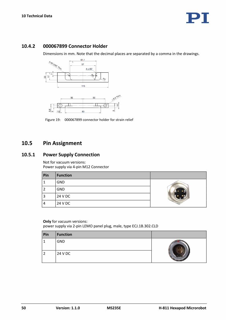
10.4.2 000067899 Connector Holder Dimensions in mm. Note that the decimal places are separated by a comma in the drawings.
Figure 19: 000067899 connector holder for strain relief
10.5 Pin Assignment
10.5.1 Power Supply Connection Not for vacuum versions: Power supply via 4-pin M12 Connector
Pin Function
1 GND
2 GND
3 24 V DC
4 24 V DC
Only for vacuum versions: power supply via 2-pin LEMO panel plug, male, type ECJ.1B.302.CLD
Pin Function
1 GND
2 24 V DC

10 Technical Data
H-811 Hexapod Microrobot MS235E Version: 1.1.0 51
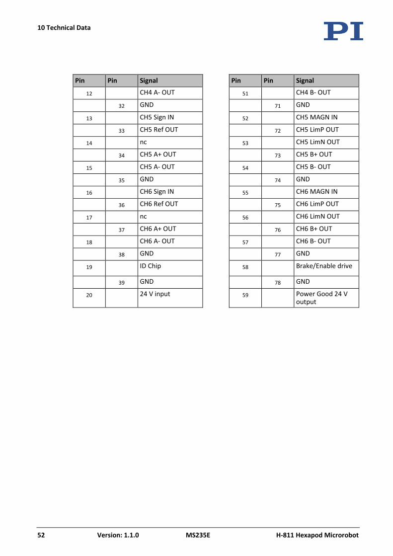
10.5.2 Data Transmission Connection Data transmission between hexapod and controller
Connector HD Sub-D 78 m
Function
All signals: TTL
Pin Assignment
Pin Pin Signal Pin Pin Signal
1 CH1 Sign IN 40 CH1 MAGN IN
21 CH1 Ref OUT 60 CH1 LimP OUT
2 nc 41 CH1 LimN OUT
22 CH1 A+ OUT 61 CH1 B+ OUT
3 CH1 A- OUT 42 CH1 B- OUT
23 GND 62 GND
4 CH2 Sign IN 43 CH2 MAGN IN
24 CH2 Ref OUT 63 CH2 LimP OUT
5 nc 44 CH2 LimN OUT
25 CH2 A+ OUT 64 CH2 B+ OUT
6 CH2 A- OUT 45 CH2 B- OUT
26 GND 65 GND
7 CH3 Sign IN 46 CH3 MAGN IN
27 CH3 Ref OUT 66 CH3 LimP OUT
8 nc 47 CH3 LimN OUT
28 CH3 A+ OUT 67 CH3 B+ OUT
9 CH3 A- OUT 48 CH3 B- OUT
29 GND 68 GND
10 CH4 Sign IN 49 CH4 MAGN IN
30 CH4 Ref OUT 69 CH4 LimP OUT
11 nc 50 CH4 LimN OUT
31 CH4 A+ OUT 70 CH4 B+ OUT
10 Technical Data
52 Version: 1.1.0 MS235E H-811 Hexapod Microrobot
Pin Pin Signal Pin Pin Signal
12 CH4 A- OUT 51 CH4 B- OUT
32 GND 71 GND
13 CH5 Sign IN 52 CH5 MAGN IN
33 CH5 Ref OUT 72 CH5 LimP OUT
14 nc 53 CH5 LimN OUT
34 CH5 A+ OUT 73 CH5 B+ OUT
15 CH5 A- OUT 54 CH5 B- OUT
35 GND 74 GND
16 CH6 Sign IN 55 CH6 MAGN IN
36 CH6 Ref OUT 75 CH6 LimP OUT
17 nc 56 CH6 LimN OUT
37 CH6 A+ OUT 76 CH6 B+ OUT
18 CH6 A- OUT 57 CH6 B- OUT
38 GND 77 GND
19 ID Chip 58 Brake/Enable drive
39 GND 78 GND
20 24 V input 59 Power Good 24 V output
11 Old Equipment Disposal
H-811 Hexapod Microrobot MS235E Version: 1.1.0 53
In accordance with EU law, electrical and electronic equipment may not be disposed of in EU member states via the municipal residual waste.
Dispose of your old equipment according to international, national, and local rules and regulations.
In order to fulfil its responsibility as the product manufacturer, Physik Instrumente (PI) GmbH & Co. KG undertakes environmentally correct disposal of all old PI equipment made available on the market after 13 August 2005 without charge.
Any old PI equipment can be sent free of charge to the following address:
Physik Instrumente (PI) GmbH & Co. KG
Auf der Roemerstr. 1
D-76228 Karlsruhe, Germany
11 Old Equipment Disposal

12 Glossary
H-811 Hexapod Microrobot MS235E Version: 1.1.0 55
User-defined coordinate system Using the controller, custom coordinate systems can be defined and used instead of the default coordinate systems.
Work with user-defined coordinate systems and the work-and-tool concept is described in the C887T0007 Technical Note.
Workspace The entirety of all combinations of translations and rotations that the hexapod can approach from the current position is referred to as the workspace.
The workspace can be limited by the following external factors:
Installation space
Dimensions and position of the load
Center of rotation The center of rotation describes the intersection of the rotational axes U, V, and W. When the default settings for the coordinate system and the center of rotation are used, the center of rotation after a reference move is located at the origin of the coordinate system (0,0,0), see the dimensional drawing of the hexapod (p. 49).
The center of rotation always moves together with the platform.
Depending on the active --> operating coordinate system, the center of rotation can be moved from the origin of the coordinate system in the X and/or Y and/or Z direction with the SPI command. The center of rotation that can be moved using the SPI command is also referred to as "pivot point".
Hexapod system The combination of hexapod, controller, cable set, and power supply is referred to as "hexapod system" in this manual.
Default coordinate system The X, Y, and Z axes of the Cartesian coordinate system are always spatially fixed, i.e., the coordinate system does not move when the platform of the hexapod moves. The X, Y and Z axes are also referred to as translational axes.
The intersection of the axes X, Y, and Z of the spatially fixed Cartesian coordinate system (0,0,0) is referred to as the origin.
12 Glossary
12 Glossary
56 Version: 1.1.0 MS235E H-811 Hexapod Microrobot
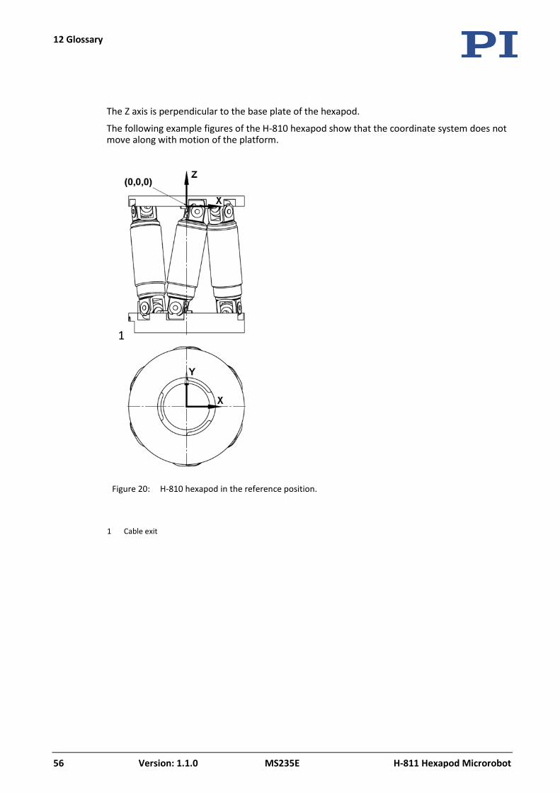
The Z axis is perpendicular to the base plate of the hexapod.
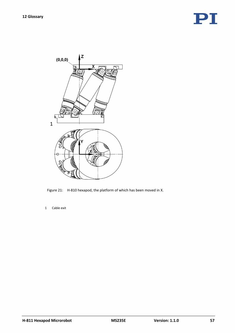
The following example figures of the H-810 hexapod show that the coordinate system does not move along with motion of the platform.
Figure 20: H-810 hexapod in the reference position.
1 Cable exit
12 Glossary
H-811 Hexapod Microrobot MS235E Version: 1.1.0 57
Figure 21: H-810 hexapod, the platform of which has been moved in X.
1 Cable exit

13 Appendix
H-811 Hexapod Microrobot MS235E Version: 1.1.0 59
In this Chapter
Explanations of the Performance Test Sheet .............................................................................. 59 EU Declaration of Conformity ...................................................................................................... 61
13.1 Explanations of the Performance Test Sheet
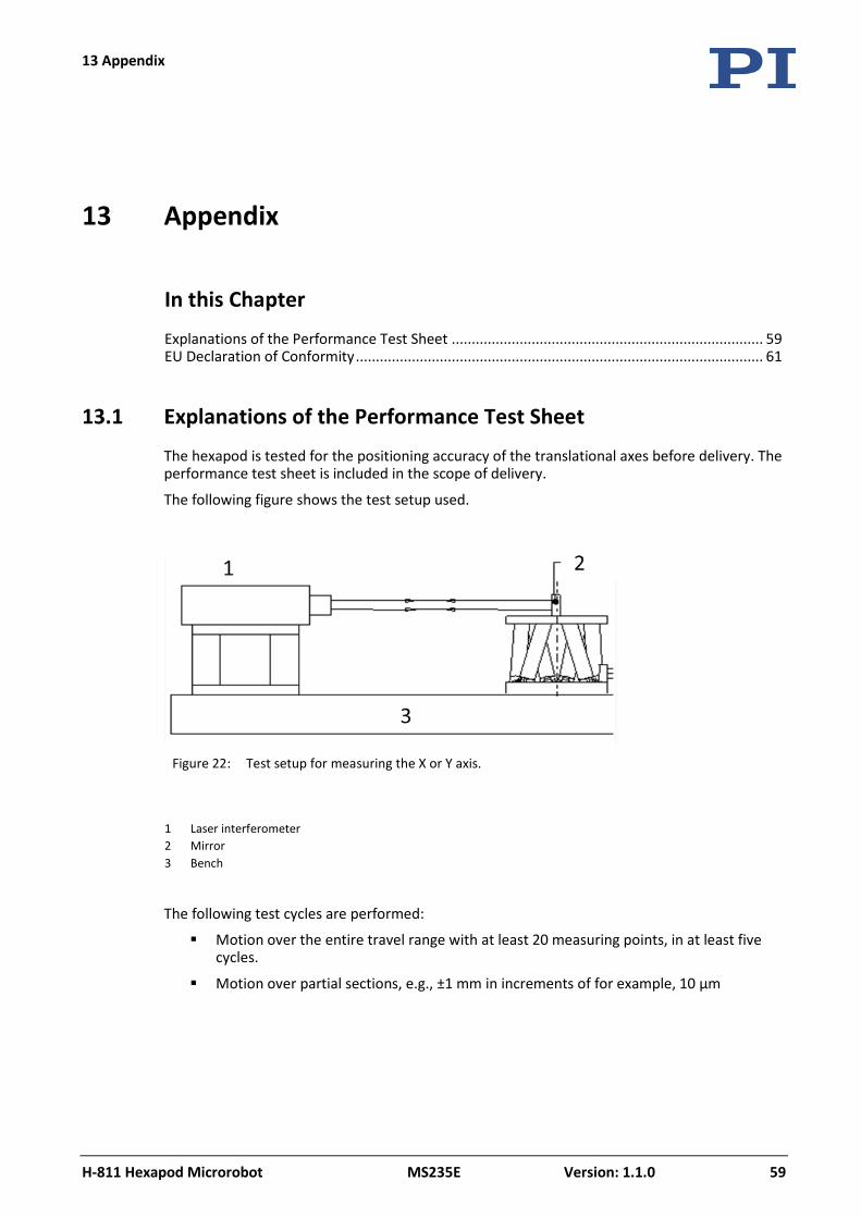
The hexapod is tested for the positioning accuracy of the translational axes before delivery. The performance test sheet is included in the scope of delivery.
The following figure shows the test setup used.
Figure 22: Test setup for measuring the X or Y axis.
1 Laser interferometer 2 Mirror 3 Bench
The following test cycles are performed:
Motion over the entire travel range with at least 20 measuring points, in at least five cycles.
Motion over partial sections, e.g., ±1 mm in increments of for example, 10 µm
13 Appendix


13 Appendix
H-811 Hexapod Microrobot MS235E Version: 1.1.0 61
13.2 EU Declaration of Conformity
For the H-811, an EU Declaration of Conformity has been issued in accordance with the following European directives:
EMC Directive
RoHS Directive
The applied standards certifying the conformity are listed below.
EMC: EN 61326-1
Safety: EN 61010-1
RoHS: EN 50581