A Spiral Microrobot Performing Navigating Linear and ...prem.hanyang.ac.kr/down/A Spiral Microrobot...
4
IEEE TRANSACTIONS ON MAGNETICS, VOL. 51, NO. 11, NOVEMBER 2015 9100404 A Spiral Microrobot Performing Navigating Linear and Drilling Motions by Magnetic Gradient and Rotating Uniform Magnetic Field for Applications in Unclogging Blocked Human Blood Vessels Gyu Bin Jang 1 , Seungmun Jeon 2 , Jaekwang Nam 2 , Wonseo Lee 2 , and Gunhee Jang 2 1 Campolindo High School, Moraga, CA 94556 USA 2 Department of Mechanical Convergence Engineering, Hanyang University, Seoul 133-791, Korea This research proposes a navigating and drilling spiral microrobot actuated by a magnetic gradient and rotating uniform magnetic field to unclog blocked human blood vessels. The proposed spiral microrobot consists of a cylindrical body that contains a cylindrical magnet and spiral drilling blades on the shaft. The cylindrical magnet can rotate freely inside the magnet slot of the body and align in any direction by applying an external uniform magnetic field. The spiral microrobot is prototyped by 3-D printing technology with ultraviolet curable acrylic plastic, then demonstrated by various experiments. These experiments show that the proposed microrobot successfully performs navigating and drilling motions, thus validating the effectiveness of the proposed spiral microrobot. Index Terms—Magnetic gradient field, magnetic navigation system (MNS), rotating uniform magnetic field, spiral microrobot. I. I NTRODUCTION M ORE than one out of three American adults have one or more types of cardiovascular disease [1]. Occlusive coronary artery disease is one of the main heart diseases that results from plaque buildup in blood vessels, blocking the flow of blood. The most common treatment uses a tapered-tip guidewire and catheter to unclog the blocked blood vessel, which is hard to control precisely through twisted and narrow blood vessels [2]. In this type of operation, cardiologists are constantly exposed to radiation from X-rays, so they wear lead shielding around their bodies to protect themselves from radiation [3]. Microrobots that are controlled by magnetic fields generated from the magnetic navigation system (MNS) have been actively investigated to replace manually controlled conventional methods, eliminating cardiologists’ exposure to radiation. Microrobots are minimally invasive technology, and they can be miniaturized because the power is supplied by a magnetic field from an outside coil system (MNS). Many researchers have investigated various mechanisms of microrobots to be applied in the human body. There are mainly two kinds of microrobots actuated by magnetic fields: microrobots actuated by a magnetic gradient [4], [5] and spiral microrobots actuated by a rotating uniform magnetic field [6], [7]. Yesin et al. [4] used a uniform magnetic field generated from a Helmholtz coil (HC) to align the magnet to the desired direction and used a magnetic gradient generated from a Maxwell coil (MC) to propel the microrobot in the desired direction. They used a motor to physically rotate a pair of an HC and an MC to navigate the microrobot in a 2-D plane by aligning the magnetic gradient and uniform magnetic field to a desired direction. Choi et al. [5] proposed Manuscript received March 17, 2015; revised April 27, 2015; accepted May 20, 2015. Date of publication May 22, 2015; date of current ver- sion October 22, 2015. Corresponding author: G. Jang (e-mail: ghjang@ hanyang.ac.kr). Color versions of one or more of the figures in this paper are available online at http://ieeexplore.ieee.org. Digital Object Identifier 10.1109/TMAG.2015.2436913 a coil system with two pairs of the HCs and MCs to navigate the microrobot in a 2-D plane. However, their microrobots were just permanent magnets magnetized in one direction, and they did not perform functions other than navigation. On the other hand, spiral microrobots have a rather complex structure with a helical or spiral blade and transversely magnetized magnets. They move by the rotational motion generated by the rotating uniform magnetic field. Honda et al. [6] proposed a spiral wire with a small magnet attached to it. This spiral wire can navigate and rotate through water by an external rotating magnetic field. Jeong et al. [7] proposed a spiral microrobot, which has a permanent magnet magnetized in a diagonal direction, and utilized a precessional magnetic field to perform navigating and drilling motions. However, their spiral microrobots cannot separate navigating and drilling motions, and rotating blades may damage healthy blood vessels while navigating through the blood vessel to reach the target point. In this paper, a navigating and drilling spiral microrobot actuated by a gradient and rotating uniform magnetic field is proposed to navigate through complex human blood vessels and unclog blocked human vessels. The proposed spiral microrobot, as shown in Fig. 1, consists of a cylindrical body that contains a cylindrical magnet and two spiral drilling blades on the shaft. The cylindrical magnet can rotate freely inside the magnet slot of the body and align in any direction by the application of an external uniform magnetic field. Then, several experiments are performed to demonstrate and verify the selective navigating and drilling motions of the prototyped spiral microrobot. II. OPERATING PRINCIPLE OF THE PROPOSED SPIRAL MICROROBOT A. Linear Propelling Motion of the Spiral Microrobot Fig. 2(a) shows a linear motion of the spiral microrobot propelled by a magnetic gradient. To move along the x -direction, the magnetization direction of the magnet inside the microrobot has to align along the x -direction by 0018-9464 © 2015 IEEE. Personal use is permitted, but republication/redistribution requires IEEE permission. See http://www.ieee.org/publications_standards/publications/rights/index.html for more information.
Transcript of A Spiral Microrobot Performing Navigating Linear and ...prem.hanyang.ac.kr/down/A Spiral Microrobot...
IEEE TRANSACTIONS ON MAGNETICS, VOL. 51, NO. 11, NOVEMBER 2015 9100404
A Spiral Microrobot Performing Navigating Linear and DrillingMotions by Magnetic Gradient and Rotating Uniform
Magnetic Field for Applications in UncloggingBlocked Human Blood Vessels
Gyu Bin Jang1, Seungmun Jeon2, Jaekwang Nam2, Wonseo Lee2, and Gunhee Jang2
1Campolindo High School, Moraga, CA 94556 USA2Department of Mechanical Convergence Engineering, Hanyang University, Seoul 133-791, Korea
This research proposes a navigating and drilling spiral microrobot actuated by a magnetic gradient and rotating uniform magneticfield to unclog blocked human blood vessels. The proposed spiral microrobot consists of a cylindrical body that contains a cylindricalmagnet and spiral drilling blades on the shaft. The cylindrical magnet can rotate freely inside the magnet slot of the body and alignin any direction by applying an external uniform magnetic field. The spiral microrobot is prototyped by 3-D printing technology withultraviolet curable acrylic plastic, then demonstrated by various experiments. These experiments show that the proposed microrobotsuccessfully performs navigating and drilling motions, thus validating the effectiveness of the proposed spiral microrobot.
Index Terms— Magnetic gradient field, magnetic navigation system (MNS), rotating uniform magnetic field, spiral microrobot.
I. INTRODUCTION
MORE than one out of three American adults have oneor more types of cardiovascular disease [1]. Occlusive
coronary artery disease is one of the main heart diseases thatresults from plaque buildup in blood vessels, blocking theflow of blood. The most common treatment uses a tapered-tipguidewire and catheter to unclog the blocked blood vessel,which is hard to control precisely through twisted and narrowblood vessels [2]. In this type of operation, cardiologists areconstantly exposed to radiation from X-rays, so they wearlead shielding around their bodies to protect themselves fromradiation [3]. Microrobots that are controlled by magneticfields generated from the magnetic navigation system (MNS)have been actively investigated to replace manually controlledconventional methods, eliminating cardiologists’ exposure toradiation. Microrobots are minimally invasive technology, andthey can be miniaturized because the power is supplied by amagnetic field from an outside coil system (MNS).
Many researchers have investigated various mechanismsof microrobots to be applied in the human body. There aremainly two kinds of microrobots actuated by magnetic fields:microrobots actuated by a magnetic gradient [4], [5] andspiral microrobots actuated by a rotating uniform magneticfield [6], [7]. Yesin et al. [4] used a uniform magnetic fieldgenerated from a Helmholtz coil (HC) to align the magnet tothe desired direction and used a magnetic gradient generatedfrom a Maxwell coil (MC) to propel the microrobot in thedesired direction. They used a motor to physically rotate apair of an HC and an MC to navigate the microrobot ina 2-D plane by aligning the magnetic gradient and uniformmagnetic field to a desired direction. Choi et al. [5] proposed
Manuscript received March 17, 2015; revised April 27, 2015; acceptedMay 20, 2015. Date of publication May 22, 2015; date of current ver-sion October 22, 2015. Corresponding author: G. Jang (e-mail: [email protected]).
Color versions of one or more of the figures in this paper are availableonline at http://ieeexplore.ieee.org.
Digital Object Identifier 10.1109/TMAG.2015.2436913
a coil system with two pairs of the HCs and MCs to navigatethe microrobot in a 2-D plane. However, their microrobotswere just permanent magnets magnetized in one direction, andthey did not perform functions other than navigation. On theother hand, spiral microrobots have a rather complex structurewith a helical or spiral blade and transversely magnetizedmagnets. They move by the rotational motion generated bythe rotating uniform magnetic field. Honda et al. [6] proposeda spiral wire with a small magnet attached to it. This spiralwire can navigate and rotate through water by an externalrotating magnetic field. Jeong et al. [7] proposed a spiralmicrorobot, which has a permanent magnet magnetized in adiagonal direction, and utilized a precessional magnetic field toperform navigating and drilling motions. However, their spiralmicrorobots cannot separate navigating and drilling motions,and rotating blades may damage healthy blood vessels whilenavigating through the blood vessel to reach the target point.
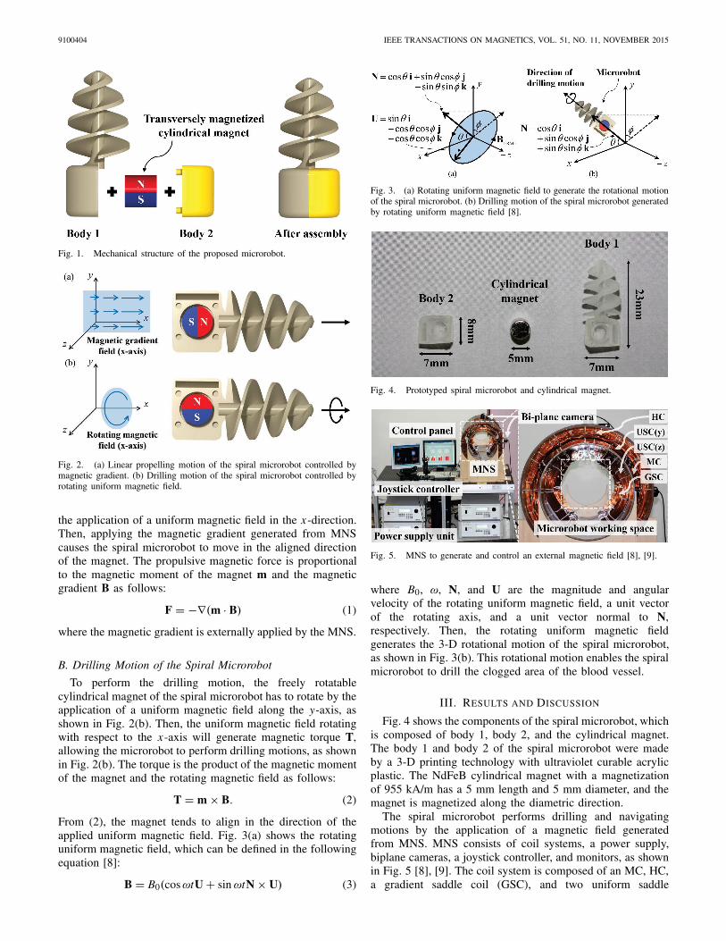
In this paper, a navigating and drilling spiral microrobotactuated by a gradient and rotating uniform magnetic fieldis proposed to navigate through complex human bloodvessels and unclog blocked human vessels. The proposedspiral microrobot, as shown in Fig. 1, consists of a cylindricalbody that contains a cylindrical magnet and two spiral drillingblades on the shaft. The cylindrical magnet can rotate freelyinside the magnet slot of the body and align in any directionby the application of an external uniform magnetic field. Then,several experiments are performed to demonstrate and verifythe selective navigating and drilling motions of the prototypedspiral microrobot.
II. OPERATING PRINCIPLE OF THE PROPOSED
SPIRAL MICROROBOT
A. Linear Propelling Motion of the Spiral Microrobot
Fig. 2(a) shows a linear motion of the spiral microrobotpropelled by a magnetic gradient. To move alongthe x-direction, the magnetization direction of the magnetinside the microrobot has to align along the x-direction by
0018-9464 © 2015 IEEE. Personal use is permitted, but republication/redistribution requires IEEE permission.See http://www.ieee.org/publications_standards/publications/rights/index.html for more information.
9100404 IEEE TRANSACTIONS ON MAGNETICS, VOL. 51, NO. 11, NOVEMBER 2015
Fig. 1. Mechanical structure of the proposed microrobot.
Fig. 2. (a) Linear propelling motion of the spiral microrobot controlled bymagnetic gradient. (b) Drilling motion of the spiral microrobot controlled byrotating uniform magnetic field.
the application of a uniform magnetic field in the x-direction.Then, applying the magnetic gradient generated from MNScauses the spiral microrobot to move in the aligned directionof the magnet. The propulsive magnetic force is proportionalto the magnetic moment of the magnet m and the magneticgradient B as follows:
F = −∇(m · B) (1)
where the magnetic gradient is externally applied by the MNS.
B. Drilling Motion of the Spiral Microrobot
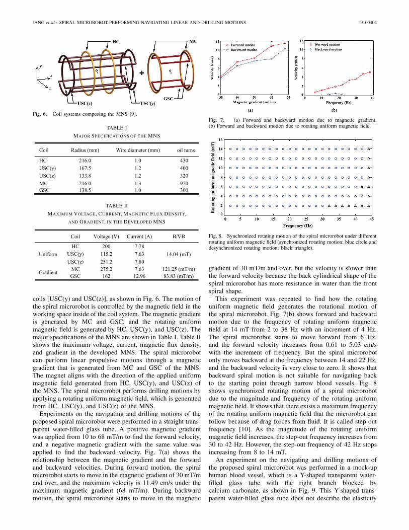
To perform the drilling motion, the freely rotatablecylindrical magnet of the spiral microrobot has to rotate by theapplication of a uniform magnetic field along the y-axis, asshown in Fig. 2(b). Then, the uniform magnetic field rotatingwith respect to the x-axis will generate magnetic torque T,allowing the microrobot to perform drilling motions, as shownin Fig. 2(b). The torque is the product of the magnetic momentof the magnet and the rotating magnetic field as follows:
T = m × B. (2)
From (2), the magnet tends to align in the direction of theapplied uniform magnetic field. Fig. 3(a) shows the rotatinguniform magnetic field, which can be defined in the followingequation [8]:
B = B0(cos ωtU + sin ωtN × U) (3)
Fig. 3. (a) Rotating uniform magnetic field to generate the rotational motionof the spiral microrobot. (b) Drilling motion of the spiral microrobot generatedby rotating uniform magnetic field [8].
Fig. 4. Prototyped spiral microrobot and cylindrical magnet.
Fig. 5. MNS to generate and control an external magnetic field [8], [9].
where B0, ω, N, and U are the magnitude and angularvelocity of the rotating uniform magnetic field, a unit vectorof the rotating axis, and a unit vector normal to N,respectively. Then, the rotating uniform magnetic fieldgenerates the 3-D rotational motion of the spiral microrobot,as shown in Fig. 3(b). This rotational motion enables the spiralmicrorobot to drill the clogged area of the blood vessel.
III. RESULTS AND DISCUSSION
Fig. 4 shows the components of the spiral microrobot, whichis composed of body 1, body 2, and the cylindrical magnet.The body 1 and body 2 of the spiral microrobot were madeby a 3-D printing technology with ultraviolet curable acrylicplastic. The NdFeB cylindrical magnet with a magnetizationof 955 kA/m has a 5 mm length and 5 mm diameter, and themagnet is magnetized along the diametric direction.
The spiral microrobot performs drilling and navigatingmotions by the application of a magnetic field generatedfrom MNS. MNS consists of coil systems, a power supply,biplane cameras, a joystick controller, and monitors, as shownin Fig. 5 [8], [9]. The coil system is composed of an MC, HC,a gradient saddle coil (GSC), and two uniform saddle
JANG et al.: SPIRAL MICROROBOT PERFORMING NAVIGATING LINEAR AND DRILLING MOTIONS 9100404
Fig. 6. Coil systems composing the MNS [9].
TABLE I
MAJOR SPECIFICATIONS OF THE MNS
TABLE II
MAXIMUM VOLTAGE, CURRENT, MAGNETIC FLUX DENSITY,
AND GRADIENT, IN THE DEVELOPED MNS
coils [USC(y) and USC(z)], as shown in Fig. 6. The motion ofthe spiral microrobot is controlled by the magnetic field in theworking space inside of the coil system. The magnetic gradientis generated by MC and GSC, and the rotating uniformmagnetic field is generated by HC, USC(y), and USC(z). Themajor specifications of the MNS are shown in Table I. Table IIshows the maximum voltage, current, magnetic flux density,and gradient in the developed MNS. The spiral microrobotcan perform linear propulsive motions through a magneticgradient that is generated from MC and GSC of the MNS.The magnet aligns with the direction of the applied uniformmagnetic field generated from HC, USC(y), and USC(z) ofthe MNS. The spiral microrobot performs drilling motions byapplying a rotating uniform magnetic field, which is generatedfrom HC, USC(y), and USC(z) of the MNS.
Experiments on the navigating and drilling motions of theproposed spiral microrobot were performed in a straight trans-parent water-filled glass tube. A positive magnetic gradientwas applied from 10 to 68 mT/m to find the forward velocity,and a negative magnetic gradient with the same value wasapplied to find the backward velocity. Fig. 7(a) shows therelationship between the magnetic gradient and the forwardand backward velocities. During forward motion, the spiralmicrorobot starts to move in the magnetic gradient of 30 mT/mand over, and the maximum velocity is 11.49 cm/s under themaximum magnetic gradient (68 mT/m). During backwardmotion, the spiral microrobot starts to move in the magnetic
Fig. 7. (a) Forward and backward motion due to magnetic gradient.(b) Forward and backward motion due to rotating uniform magnetic field.
Fig. 8. Synchronized rotating motion of the spiral microrobot under differentrotating uniform magnetic field (synchronized rotating motion: blue circle anddesynchronized rotating motion: black triangle).
gradient of 30 mT/m and over, but the velocity is slower thanthe forward velocity because the back cylindrical shape of thespiral microrobot has more resistance in water than the frontspiral shape.
This experiment was repeated to find how the rotatinguniform magnetic field generates the rotational motion ofthe spiral microrobot. Fig. 7(b) shows forward and backwardmotion due to the frequency of rotating uniform magneticfield at 14 mT from 2 to 38 Hz with an increment of 4 Hz.The spiral microrobot starts to move forward from 6 Hz,and the forward velocity increases from 0.61 to 5.03 cm/swith the increment of frequency. But the spiral microrobotonly moves backward at the frequency between 14 and 22 Hz,and the backward velocity is very close to zero. It shows thatbackward spiral motion is not suitable for navigating backto the starting point through narrow blood vessels. Fig. 8shows synchronized rotating motion of a spiral microrobotdue to the magnitude and frequency of the rotating uniformmagnetic field. It shows that there exists a maximum frequencyof the rotating uniform magnetic field that the microrobot canfollow because of drag forces from fluid. It is called step-outfrequency [10]. As the magnitude of the rotating uniformmagnetic field increases, the step-out frequency increases from30 to 42 Hz. However, the step-out frequency of 42 Hz stopsincreasing from 8 to 14 mT.
An experiment on the navigating and drilling motions ofthe proposed spiral microrobot was performed in a mock-uphuman blood vessel, which is a Y-shaped transparent water-filled glass tube with the right branch blocked bycalcium carbonate, as shown in Fig. 9. This Y-shaped trans-parent water-filled glass tube does not describe the elasticity
9100404 IEEE TRANSACTIONS ON MAGNETICS, VOL. 51, NO. 11, NOVEMBER 2015
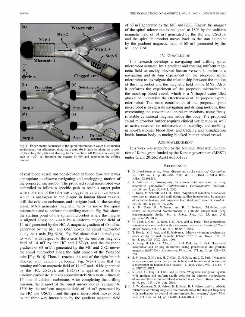
Fig. 9. Experimental sequences of the spiral microrobot in water-filled tubularenvironment. (a) Alignment along the x-axis. (b) Propulsion along the x-axis.(c) Selecting the path and steering to the direction. (d) Propulsion along thepath of −30°. (e) Rotating the magnet by 90° and generating the drillingmotion.
of real blood vessel and non-Newtonian blood flow, but it wasappropriate to observe navigating and unclogging motion ofthe proposed microrobot. The proposed spiral microrobot wascontrolled to follow a specific path to reach a target pointwhere one end of the tube was clogged by calcium carbonate,which is analogous to the plaque in human blood vessels,drill the calcium carbonate, and navigate back to the startingpoint. MNS generates magnetic fields to move the spiralmicrorobot and to perform the drilling motion. Fig. 9(a) showsthe starting point of the spiral microrobot where the magnetis aligned along the x-axis by a uniform magnetic field of14 mT generated by the HC. A magnetic gradient of 68 mT/mgenerated by the MC and GSC moves the spiral microrobotalong the x-axis [Fig. 9(b)]. Fig. 9(c) shows that it is realignedto −30° with respect to the x-axis by the uniform magneticfield of 14 mT by the HC and USC(y), and the magneticgradient of 68 mT/m generated by the MC and GSC movesthe spiral microrobot along the right branch of the Y-shapedtube [Fig. 9(d)]. Then, it reaches the end of the right branchblocked with calcium carbonate. Fig. 9(e) shows that therotating uniform magnetic field of 14 mT and 16 Hz generatedby the HC, USC(y), and USC(z) is applied to drill thecalcium carbonate. It takes approximately 90 s to drill through15 mm of calcium carbonate. After completing the drillingmission, the magnet of the spiral microrobot is realigned to150° by the uniform magnetic field of 14 mT generated bythe HC and USC(y), and the spiral microrobot moves backto the three-way intersection by the gradient magnetic field
of 68 mT generated by the MC and GSC. Finally, the magnetof the spiral microrobot is realigned to 180° by the uniformmagnetic field of 14 mT generated by the HC and USC(y),and the spiral microrobot moves back to the starting pointby the gradient magnetic field of 68 mT generated by theMC and GSC.
IV. CONCLUSION
This research develops a navigating and drilling spiralmicrorobot actuated by a gradient and rotating uniform mag-netic field to unclog blocked human vessels. It performs anavigating and drilling experiment on the proposed spiralmicrorobot to investigate the relationship between the motionof the microrobot and the magnetic field of the MNS. Also,it performs the experiment of the proposed microrobot inthe mock-up blood vessel, which is a Y-shaped water-filledglass tube, to validate the effectiveness of the proposed spiralmicrorobot. The main contribution of the proposed spiralmicrorobot is to separate navigating and drilling motions, thusovercoming the conventional spiral microrobots, using freelyrotatable cylindrical magnets inside the body. The proposedspiral microrobot further requires clinical verification as wellas active research on miniaturization, stability, and mobilityin non-Newtonian blood flow, and tracking and visualizationinside human body to unclog blocked human blood vessel.
ACKNOWLEDGMENT
This work was supported by the National Research Founda-tion of Korea grant funded by the Korean government (MEST)under Grant 2015R1A2A1A05001837.
REFERENCES
[1] D. Lloyd-Jones et al., “Heart disease and stroke statistics,” Circulation,vol. 119, no. 3, pp. 480–486, 2009, doi: 10.1161/CIRCULATION-AHA.108.191259.
[2] S. Saito et al., “Angioplasty for chronic total occlusion by usingtapered-tip guidewires,” Catheterization Cardiovascular Intervent.,vol. 59, no. 3, pp. 305–311, 2003.
[3] E. Kuon, M. Schmitt, and J. B. Dahm, “Significant reduction of radiationexposure to operator and staff during cardiac interventions by analysisof radiation leakage and improved lead shielding,” Amer. J. Cardiol.,vol. 89, no. 1, pp. 44–49, 2002.
[4] K. B. Yesin, K. Vollmers, and B. J. Nelson, “Modeling andcontrol of untethered biomicrorobots in a fluidic environment usingelectromagnetic fields,” Int. J. Robot. Res., vol. 25, nos. 5–6,pp. 527–536, 2006.
[5] H. Choi, J. Choi, G. Jang, J.-O. Park, and S. Park, “Two-dimensionalactuation of a microrobot with a stationary two-pair coil system,” SmartMater. Struct., vol. 18, no. 5, p. 055007, 2009.
[6] T. Honda, K. I. Arai, and K. Ishiyama, “Micro swimming mechanismspropelled by external magnetic fields,” IEEE Trans. Magn., vol. 32,no. 5, pp. 5085–5087, Sep. 1996.
[7] S. Jeong, H. Choi, K. Cha, J. Li, J.-O. Park, and S. Park, “Enhancedlocomotive and drilling microrobot using precessional and gradientmagnetic field,” Sens. Actuators A, Phys., vol. 171, no. 2, pp. 429–435,2011.
[8] S. M. Jeon, G. H. Jang, H. C. Choi, S. H. Park, and J. O. Park, “Magneticnavigation system for the precise helical and translational motions ofa microrobot in human blood vessels,” J. Appl. Phys., vol. 111, no. 7,p. 07E702, 2012.
[9] S. Jeon, G. Jang, H. Choi, and S. Park, “Magnetic navigation systemwith gradient and uniform saddle coils for the wireless manipulationof micro-robots in human blood vessels,” IEEE Trans. Magn., vol. 46,no. 6, pp. 1943–1946, Jun. 2010.
[10] A. W. Mahoney, N. D. Nelson, K. E. Peyer, B. J. Nelson, and J. J. Abbott,“Behavior of rotating magnetic microrobots above the step-out frequencywith application to control of multi-microrobot systems,” Appl. Phys.Lett., vol. 104, no. 14, pp. 144101-1–144101-4, 2014.